EP4390157A1 - Screw - Google Patents
Screw Download PDFInfo
- Publication number
- EP4390157A1 EP4390157A1 EP23218519.9A EP23218519A EP4390157A1 EP 4390157 A1 EP4390157 A1 EP 4390157A1 EP 23218519 A EP23218519 A EP 23218519A EP 4390157 A1 EP4390157 A1 EP 4390157A1
- Authority
- EP
- European Patent Office
- Prior art keywords
- screw
- thread
- shank
- tip
- head
- Prior art date
- Legal status (The legal status is an assumption and is not a legal conclusion. Google has not performed a legal analysis and makes no representation as to the accuracy of the status listed.)
- Pending
Links
Images





Classifications
-
- F—MECHANICAL ENGINEERING; LIGHTING; HEATING; WEAPONS; BLASTING
- F16—ENGINEERING ELEMENTS AND UNITS; GENERAL MEASURES FOR PRODUCING AND MAINTAINING EFFECTIVE FUNCTIONING OF MACHINES OR INSTALLATIONS; THERMAL INSULATION IN GENERAL
- F16B—DEVICES FOR FASTENING OR SECURING CONSTRUCTIONAL ELEMENTS OR MACHINE PARTS TOGETHER, e.g. NAILS, BOLTS, CIRCLIPS, CLAMPS, CLIPS OR WEDGES; JOINTS OR JOINTING
- F16B35/00—Screw-bolts; Stay-bolts; Screw-threaded studs; Screws; Set screws
- F16B35/04—Screw-bolts; Stay-bolts; Screw-threaded studs; Screws; Set screws with specially-shaped head or shaft in order to fix the bolt on or in an object
- F16B35/06—Specially-shaped heads
-
- F—MECHANICAL ENGINEERING; LIGHTING; HEATING; WEAPONS; BLASTING
- F16—ENGINEERING ELEMENTS AND UNITS; GENERAL MEASURES FOR PRODUCING AND MAINTAINING EFFECTIVE FUNCTIONING OF MACHINES OR INSTALLATIONS; THERMAL INSULATION IN GENERAL
- F16B—DEVICES FOR FASTENING OR SECURING CONSTRUCTIONAL ELEMENTS OR MACHINE PARTS TOGETHER, e.g. NAILS, BOLTS, CIRCLIPS, CLAMPS, CLIPS OR WEDGES; JOINTS OR JOINTING
- F16B25/00—Screws that cut thread in the body into which they are screwed, e.g. wood screws
- F16B25/0036—Screws that cut thread in the body into which they are screwed, e.g. wood screws characterised by geometric details of the screw
- F16B25/0042—Screws that cut thread in the body into which they are screwed, e.g. wood screws characterised by geometric details of the screw characterised by the geometry of the thread, the thread being a ridge wrapped around the shaft of the screw
- F16B25/0057—Screws that cut thread in the body into which they are screwed, e.g. wood screws characterised by geometric details of the screw characterised by the geometry of the thread, the thread being a ridge wrapped around the shaft of the screw the screw having distinct axial zones, e.g. multiple axial thread sections with different pitch or thread cross-sections
-
- F—MECHANICAL ENGINEERING; LIGHTING; HEATING; WEAPONS; BLASTING
- F16—ENGINEERING ELEMENTS AND UNITS; GENERAL MEASURES FOR PRODUCING AND MAINTAINING EFFECTIVE FUNCTIONING OF MACHINES OR INSTALLATIONS; THERMAL INSULATION IN GENERAL
- F16B—DEVICES FOR FASTENING OR SECURING CONSTRUCTIONAL ELEMENTS OR MACHINE PARTS TOGETHER, e.g. NAILS, BOLTS, CIRCLIPS, CLAMPS, CLIPS OR WEDGES; JOINTS OR JOINTING
- F16B25/00—Screws that cut thread in the body into which they are screwed, e.g. wood screws
- F16B25/0036—Screws that cut thread in the body into which they are screwed, e.g. wood screws characterised by geometric details of the screw
- F16B25/0042—Screws that cut thread in the body into which they are screwed, e.g. wood screws characterised by geometric details of the screw characterised by the geometry of the thread, the thread being a ridge wrapped around the shaft of the screw
- F16B25/0057—Screws that cut thread in the body into which they are screwed, e.g. wood screws characterised by geometric details of the screw characterised by the geometry of the thread, the thread being a ridge wrapped around the shaft of the screw the screw having distinct axial zones, e.g. multiple axial thread sections with different pitch or thread cross-sections
- F16B25/0063—Screws that cut thread in the body into which they are screwed, e.g. wood screws characterised by geometric details of the screw characterised by the geometry of the thread, the thread being a ridge wrapped around the shaft of the screw the screw having distinct axial zones, e.g. multiple axial thread sections with different pitch or thread cross-sections with a non-threaded portion on the shaft of the screw
-
- F—MECHANICAL ENGINEERING; LIGHTING; HEATING; WEAPONS; BLASTING
- F16—ENGINEERING ELEMENTS AND UNITS; GENERAL MEASURES FOR PRODUCING AND MAINTAINING EFFECTIVE FUNCTIONING OF MACHINES OR INSTALLATIONS; THERMAL INSULATION IN GENERAL
- F16B—DEVICES FOR FASTENING OR SECURING CONSTRUCTIONAL ELEMENTS OR MACHINE PARTS TOGETHER, e.g. NAILS, BOLTS, CIRCLIPS, CLAMPS, CLIPS OR WEDGES; JOINTS OR JOINTING
- F16B25/00—Screws that cut thread in the body into which they are screwed, e.g. wood screws
- F16B25/0036—Screws that cut thread in the body into which they are screwed, e.g. wood screws characterised by geometric details of the screw
- F16B25/0084—Screws that cut thread in the body into which they are screwed, e.g. wood screws characterised by geometric details of the screw characterised by geometric details of the tip
-
- F—MECHANICAL ENGINEERING; LIGHTING; HEATING; WEAPONS; BLASTING
- F16—ENGINEERING ELEMENTS AND UNITS; GENERAL MEASURES FOR PRODUCING AND MAINTAINING EFFECTIVE FUNCTIONING OF MACHINES OR INSTALLATIONS; THERMAL INSULATION IN GENERAL
- F16B—DEVICES FOR FASTENING OR SECURING CONSTRUCTIONAL ELEMENTS OR MACHINE PARTS TOGETHER, e.g. NAILS, BOLTS, CIRCLIPS, CLAMPS, CLIPS OR WEDGES; JOINTS OR JOINTING
- F16B25/00—Screws that cut thread in the body into which they are screwed, e.g. wood screws
- F16B25/10—Screws performing an additional function to thread-forming, e.g. drill screws or self-piercing screws
- F16B25/106—Screws performing an additional function to thread-forming, e.g. drill screws or self-piercing screws by means of a self-piercing screw-point, i.e. without removing material
-
- F—MECHANICAL ENGINEERING; LIGHTING; HEATING; WEAPONS; BLASTING
- F16—ENGINEERING ELEMENTS AND UNITS; GENERAL MEASURES FOR PRODUCING AND MAINTAINING EFFECTIVE FUNCTIONING OF MACHINES OR INSTALLATIONS; THERMAL INSULATION IN GENERAL
- F16B—DEVICES FOR FASTENING OR SECURING CONSTRUCTIONAL ELEMENTS OR MACHINE PARTS TOGETHER, e.g. NAILS, BOLTS, CIRCLIPS, CLAMPS, CLIPS OR WEDGES; JOINTS OR JOINTING
- F16B25/00—Screws that cut thread in the body into which they are screwed, e.g. wood screws
- F16B25/001—Screws that cut thread in the body into which they are screwed, e.g. wood screws characterised by the material of the body into which the screw is screwed
- F16B25/0015—Screws that cut thread in the body into which they are screwed, e.g. wood screws characterised by the material of the body into which the screw is screwed the material being a soft organic material, e.g. wood or plastic
-
- F—MECHANICAL ENGINEERING; LIGHTING; HEATING; WEAPONS; BLASTING
- F16—ENGINEERING ELEMENTS AND UNITS; GENERAL MEASURES FOR PRODUCING AND MAINTAINING EFFECTIVE FUNCTIONING OF MACHINES OR INSTALLATIONS; THERMAL INSULATION IN GENERAL
- F16B—DEVICES FOR FASTENING OR SECURING CONSTRUCTIONAL ELEMENTS OR MACHINE PARTS TOGETHER, e.g. NAILS, BOLTS, CIRCLIPS, CLAMPS, CLIPS OR WEDGES; JOINTS OR JOINTING
- F16B25/00—Screws that cut thread in the body into which they are screwed, e.g. wood screws
- F16B25/0036—Screws that cut thread in the body into which they are screwed, e.g. wood screws characterised by geometric details of the screw
- F16B25/0042—Screws that cut thread in the body into which they are screwed, e.g. wood screws characterised by geometric details of the screw characterised by the geometry of the thread, the thread being a ridge wrapped around the shaft of the screw
- F16B25/0047—Screws that cut thread in the body into which they are screwed, e.g. wood screws characterised by geometric details of the screw characterised by the geometry of the thread, the thread being a ridge wrapped around the shaft of the screw the ridge being characterised by its cross-section in the plane of the shaft axis
-
- F—MECHANICAL ENGINEERING; LIGHTING; HEATING; WEAPONS; BLASTING
- F16—ENGINEERING ELEMENTS AND UNITS; GENERAL MEASURES FOR PRODUCING AND MAINTAINING EFFECTIVE FUNCTIONING OF MACHINES OR INSTALLATIONS; THERMAL INSULATION IN GENERAL
- F16B—DEVICES FOR FASTENING OR SECURING CONSTRUCTIONAL ELEMENTS OR MACHINE PARTS TOGETHER, e.g. NAILS, BOLTS, CIRCLIPS, CLAMPS, CLIPS OR WEDGES; JOINTS OR JOINTING
- F16B25/00—Screws that cut thread in the body into which they are screwed, e.g. wood screws
- F16B25/0036—Screws that cut thread in the body into which they are screwed, e.g. wood screws characterised by geometric details of the screw
- F16B25/0042—Screws that cut thread in the body into which they are screwed, e.g. wood screws characterised by geometric details of the screw characterised by the geometry of the thread, the thread being a ridge wrapped around the shaft of the screw
- F16B25/0052—Screws that cut thread in the body into which they are screwed, e.g. wood screws characterised by geometric details of the screw characterised by the geometry of the thread, the thread being a ridge wrapped around the shaft of the screw the ridge having indentations, notches or the like in order to improve the cutting behaviour
Definitions
- the present invention relates to a screw.
- Fasteners may be used to fasten two or more parts together.
- a fastener may be used to fasten a metal bracket to a wooden part, or to fasten two metal parts together, or two wooden parts together.
- Screws have been known and available for many years, and are generally made of metal and include a shank having a head at one end, and a tip at an opposite end to the head.
- the present invention aims to overcome these disadvantages.
- a screw comprising a head and a tip at opposite ends, and a shank extending between the head and the tip, the head comprising: a top portion, and a frustoconical portion arranged between the top portion and the shank, wherein the frustoconical portion comprises a step defining an annular recess towards the shank; and at least one radial rib arranged in the recess and extending towards the shank.
- the rib(s) engage with the part to be fixated, which improves pull-out resistance and therefore provides improved fixation. Even when the part vibrates, corrodes, or is otherwise moved, the head of the screw remains fixed to the part via the rib(s), improving contact between the screw and the part to be fixated. This allows the screw to be more firmly held during use, making the screw less susceptible to loosening.
- Another advantage of having at least one radial rib extending towards the shank and arranged within the recess defined by a step in the frustoconical portion is that the frustoconical portion shields the radial rib(s) from milling the part to be fixated upon insertion and rotation of the screw.
- the frustoconical portion comprises a circumferential surface facing the shank and the tip.
- the circumferential surface is arranged substantially perpendicular to an axis of the screw.
- step segments the frustoconical portion into a first frustoconical part extending from the top portion to the step, and a second frustoconical part extending from the step towards the shank.
- a diameter of the first frustoconical part is greater than a diameter of the second frustoconical part.
- the head of the screw comprises a plurality of ribs evenly distributed around the head. This is particularly advantageous because the ribs uniformly contact the part to be fixated and there is provided multiple points of contact between the screw and the part.
- the, or each, rib has a radial dimension that decreases towards the shank.
- the, or each, rib comprises an axial edge, the, or each, rib being symmetrical with respect to an axial plane containing the axial edge.
- the shank comprises a first portion having a first thread, and a second portion between the first portion and the tip, the second portion having a second thread.
- the first thread and the second thread are orientated in opposing turning directions.
- the second thread has a thread angle that is larger than a thread angle of the first thread.
- the shank comprises a thread comprising a first part, and a second part arranged between the first part and the tip.
- a thread angle of the thread increases continuously from the first part to the second part.
- a thread angle of the thread is constant along the first part and/or the second part.
- a length of the second part is at least twice the diameter of the shank. In examples, the length of the second part is between two and four times the diameter of the shank.
- a screw comprising a head and a tip at opposite ends, and a shank extending between the head and the tip, wherein the shank comprises at least one drilling thread configured for cutting into wood.
- a diameter of the at least one drilling thread is substantially equal to a diameter of the shank.
- a screw comprising a head and a tip at opposite ends, and a shank extending between the head and the tip, wherein the shank comprises a main screw thread, and the tip comprises a drilling thread configured for cutting into wood.
- the main screw thread extends towards the tip. In examples, the main screw thread extends along the tip. In examples, the main screw thread partially extends along the tip. In other examples, the main screw thread extends along the entire tip.
- the at least one drilling thread has a pitch that is greater than a pitch of the main screw thread.
- an external diameter of the at least one drilling thread is smaller than an externa diameter of the main screw thread.
- an external diameter of the at least one drilling thread is substantially equal to the diameter of the shank. In examples, an external diameter of the at least one drilling thread is equal to the diameter of the shank with a tolerance t. In examples, the tolerance t may be of +0.0 to +0.5mm, preferably +0.0 to +0.2mm.
- the tip comprises a plurality of drilling threads.
- the plurality of drilling threads are regularly distributed around the tip. This advantageously provides multiple points of cutting.
- the head comprises: a top portion, and a frustoconical portion arranged between the top portion and the shank, wherein the frustoconical portion comprises a step defining an annular recess towards the shank; and at least one radial rib arranged in the recess and extending towards the shank.
- the rib(s) engage with the part to be fixated, which improves pull-out resistance and therefore provides improved fixation. Even when the part vibrates, corrodes, or is otherwise moved, the head of the screw remains fixed to the part via the rib(s), improving contact between the screw and the part to be fixated. This allows the screw to be more firmly held during use, making the screw less susceptible to loosening.
- Another advantage of having at least one radial rib extending towards the shank and arranged within the recess defined by a step in the frustoconical portion is that the frustoconical portion shields the radial rib(s) from milling the part to be fixated upon insertion and rotation of the screw
- the frustoconical portion comprises a circumferential surface facing the shank and the tip.
- the circumferential surface is arranged substantially perpendicular to an axis of the screw.
- the step segments the frustoconical portion into a first frustoconical part extending from the top portion to the step, and a second frustoconical part extending from the step towards the shank.
- a diameter of the first frustoconical part is greater than a diameter of the second frustoconical part.
- the head of the screw comprises a plurality of ribs evenly distributed around the head.
- the provision of a plurality of ribs further increases pull-out resistance and improve fixation.
- the, or each, rib has a radial dimension that decreases towards the shank.
- the, or each, rib comprises an axial edge, the, or each, rib being symmetrical with respect to an axial plane containing the axial edge.
- the, or each, rib is asymmetrical with respect to an axial plane containing the axial edge.
- the shank comprises a first portion having a first thread, and a second portion between the first portion and the tip, the second portion having a second thread.
- the first thread and the second thread are orientated in opposing turning directions.
- the second thread has a thread angle that is larger than a thread angle of the first thread.
- the thread of the shank comprises a first part, and a second part arranged between the first part and he tip.
- a thread angle of the thread increases continuously from the first part to the second part.
- a thread angle of the thread is constant along the first part and/or the second part.
- a length of the second part and the tip is at least twice the diameter of the shank. In examples, a length of the second part and the tip is between two and four times the diameter of the shank.
- a combined length of the second part and the tip is at least twice the diameter of the shank. In examples, a combined length of the second part and the tip is between two and four times the diameter of the shank.
- a screw comprising a head and a tip at opposite ends, and a shank extending between the head and the tip, wherein the shank comprises a thread comprising a first part, and a second part arranged between the first part and the tip, wherein a thread angle of the second part is greater than a thread angle of the first part.
- the thread angle of the second part is between 5 and 15 degrees greater than the thread angle of the first part. In examples, the thread angle of the second part is 10 degrees greater than the thread angle of the first part.
- a screw comprising a head and a tip at opposite ends, and a shank extending between the head and the tip, wherein the shank comprises a thread comprising a first part, and a second part arranged between the first part and the tip, wherein a length of the second part and the tip is at least twice the diameter of the shank.
- the combined length of the second part and the tip is at least twice the diameter of the shank.
- the length of the second part and the tip is between two and four times the diameter of the shank. In examples, the combined length of the second part and the tip is between two and four times the diameter of the shank.
- the screw is a wood screw.
- the screw has a head and a shank axially prolonging the head until a free end or tip.
- the head has a top portion.
- the top portion may be substantially cylindrical.
- the top portion may have a top surface.
- the top surface may be flat, or raised (e.g., oval).
- the top surface may have a tool socket.
- the head has a substantially frustoconical or tulip-shape portion arranged between the top portion and the shank.
- the diameter of the frustoconical portion may decrease from the top portion to the shank.
- the frustoconical portion has a step or shoulder defining an annular recess towards the shank and/or a circumferential surface facing the shank and the tip.
- the surface may be substantially perpendicular to the axis of the screw.
- the surface may be substantially flat.
- the step may divide the frustoconical portion into a first frustoconical part and a second frustoconical part.
- the first frustoconical part may extend from the top portion to the step.
- the second frustoconical part may extend from the step towards the shank.
- the frustoconical portion may have a greater diameter between the step and the top portion (at the first frustoconical part) than between the step and the shank (at the second frustoconical part).
- the head has at least one rib.
- the rib(s) may be radial.
- the rib(s) may be oriented axially.
- the rib(s) may be regularly distributed around the head.
- the rib(s) may be in the annular recess.
- the rib(s) may extend from the surface towards the shank.
- a radial dimension of the rib(s) may decrease from the surface towards the shank.
- the rib(s) may have a substantially pyramidal shape.
- the rib(s) may have an axial edge.
- the rib(s) may be asymmetrical with respect to an axial plane containing their axial edge.
- the axial edge may be common to a first face oriented towards a first direction of rotation and an opposite second face.
- the second face may be larger than the first face.
- the first direction of rotation may be to the left, when the screw is viewed with the head up.
- the maximum diameter of the rib(s) may
- the head has at least one axial notch.
- the notch(es) may be U-shaped.
- the notch(es) may extend at least partially along the top portion and/or along the frustoconical portion.
- the notch(es) may extend along the first frustoconical part.
- the notch(es) may be axially aligned with the rib(s) .
- the notch(es) may be made for air and/or oil passage when realizing the rib(s).
- the shank has a first portion.
- the first portion may have a first thread.
- the first thread may turn right towards the tip, when the screw is viewed with the head up.
- the shank has a second portion.
- the second portion may be between the first portion and the tip.
- the second portion has a second thread.
- the second thread may turn left towards the tip, when the screw is viewed with the head up.
- the second thread may continue along the tip.
- the second thread may have a thread angle ⁇ that is larger at a first part of the second thread than at a second part of the second thread.
- the second part may be closer to the tip than the first part.
- the thread angle ⁇ may be constant along the first part.
- the thread angle ⁇ may be constant along the second part.
- the thread angle ⁇ may increase from the first part to the second part.
- the thread angle ⁇ may continuously and regularly increase from the first part to the second part.
- the thread angle ⁇ may increase by approximatively 10° from the first part to the second part.
- the thread angle ⁇ may be equal at the second part and at the tip.
- the length L of the second part and the tip along the axis of the screw may be equal to at least twice the diameter of the second portion (i.e. shank).
- the second thread has axial notches or cuts at an area close to the tip.
- the notches may be V-shaped.
- the notches may be regularly distributed around the second portion.
- the notches may define spikes or peaks or teeth along the second thread.
- the notches may be axially aligned.
- the shank has a third portion.
- the third portion may be between the head and the first portion.
- the third portion may have no thread.
- the tip has at least one drilling or cutting thread.
- the drilling threads may be regularly distributed around the tip.
- the drilling threads may be completely or almost completely located at the tip.
- the drilling threads may turn left away from the shank, when the screw is viewed with the head up.
- the pitch of the drilling threads may be greater than the pitch of the second thread.
- the external diameter of the drilling threads may be inferior to the external diameter of the second thread.
- the drilling threads may have a diameter which is substantially equal to the diameter of the second portion.
- the diameter of the drilling threads may be equal to the diameter of the second portion with a tolerance t.
- the tolerance t may be of +0.0 to +0.5mm, preferably +0.0 to +0.2mm.
- the tip may be pointed.
- the screw is used for fastening wooden parts together.
- the screw may also, or alternatively, be used for fastening a metal bracket having a hole designed to receive a countersunk screw, for example a 90° countersunk screw, to wooden part(s), the head of the screw being received in said hole.
- the terms 'connected', 'attached', 'coupled' and 'mounted' are intended to include direct connections between two members without any other members interposed therebetween, as well as, indirect connections between members in which one or more other members are interposed therebetween.
- the terminology includes the words specifically mentioned above, derivatives thereof, and words of similar import.
- FIG. 1 shows a perspective view of a screw 10.
- the screw 10 is a wood screw.
- the screw 10 has a head 11 and a tip 13 at opposite ends, and a shank 12 extending between the head 11 and the tip 13.
- the shank 12 includes a main screw thread 29.
- the main screw thread 29 extends along the tip 13.
- the tip 13 includes at least one drilling thread 33.
- the at least one drilling thread 33 may be configured for cutting into wood.
- the shank 12 axially prolongs the head until it reaches the tip 13 at a free end.
- the shank 12 in this example has three portions: a first portion 26 at a central region in the shank 12; a second portion 28 between the first portion 26 and the tip 13; and a third portion 32 between the head 11 and the first portion 26 and having no thread.
- the shank 12 may instead include a single portion having the main screw thread 29.
- the shank 12 may be provided with a main screw thread 29 (e.g. at the second portion 28), without the first portion 26 and without the third portion 32.
- the main screw thread 29 may extend the entire length of the shank 12. In other examples, the main screw thread 29 may extend only partially along the length of the shank 12.
- the main screw thread 29 may extend towards the tip. In examples, the main screw thread extends along the tip. In examples, the main screw thread partially extends along the tip. In other examples, the main screw thread extends along the entire tip.
- FIG. 2 and FIG. 3 show an enlarged view of the head 11.
- the head 11 includes a top portion 14, which is substantially cylindrical in this example.
- the top portion 14 is provided with a top surface 15.
- the top surface 15 is flat in this example, although it is envisaged that in other examples the top surface 15 may be raised.
- the top surface 15 of the head 11 is provided with a tool socket 151 which is shaped and configured for the insertion of a tool (not shown).
- the head 11 has a substantially frustoconical portion 16 (i.e. tulip-shaped portion) arranged between the top portion 14 and the shank 12.
- the diameter of the frustoconical portion 16 decreases from the top portion 14 towards the shank 12.
- the frustoconical portion 16 is provided with a step 17 (i.e. shoulder) that defines an annular recess (50, FIG. 5 ) towards the shank 12.
- the frustoconical portion 16 includes a circumferential surface 18 that faces the shank 12 and the tip 13.
- the circumferential surface 18 is substantially perpendicular to the axis of the screw 10, and is a substantially flat surface.
- the step 17 of the frustoconical portion 16 divides the frustoconical portion 16 into a first frustoconical part 19 and a second frustoconical part 20.
- the first frustoconical part 19 extends from the top portion 14 to the step 17, while the second frustoconical part 20 extends from the step 17 towards the shank 12.
- the diameter at the first frustoconical part 19 is greater than the diameter at the second frustoconical part 20.
- the head 11 includes at least one radial rib 21.
- the head 11 is provided with six radial ribs 21, although only three ribs 21 are illustrated in the view of FIG. 2 .
- the ribs 21 are oriented axially, and are regularly distributed around the head 11.
- the ribs 21 are located within the annular recess (50, FIG. 5 ).
- the ribs 21 extend from the circumferential surface 18 towards the shank 12.
- a radial dimension of the ribs 21 decreases from the surface 18 towards the shank 12, such that the ribs 21 have a substantially pyramidal shape.
- the ribs 21 are provided with an axial edge 22.
- the ribs 21 are arranged asymmetrically with respect to an axial plane containing the axial edge 22.
- the axial edge 22 in this example is common to a first face 23 oriented towards a first direction of rotation and an opposite second face 24.
- the first direction of rotation may be to the left, when the screw 10 is viewed with the head 11 up.
- the second face 24 is larger than the first face 23.
- the maximum diameter of the ribs 21 is substantially equal to the maximum diameter of the head 11 at the step 17.
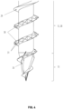
- FIG. 4 shows the tip 13 end of the screw 10, which illustrates a second thread 29 (i.e. main screw thread) of the second portion 28.
- the second thread 29 turns left towards the tip 13, when the screw 10 is viewed with the head 11 up.
- the second thread 29 continues along the tip 13.
- the second thread 29 includes axial notches 30 (i.e. cuts) at an area close to the tip 13.
- the notches 30 are V-shaped in this example.
- the notches 30 are regularly distributed around the second portion 28.
- the notches 30 define teeth 31 (e.g. spikes or peaks) along the second thread 29. In this example, the notches 30 are axially aligned.
- the tip 13 is pointed and includes at least one drilling thread 33 (i.e. cutting thread).
- the tip 13 includes a plurality of drilling threads 33 that are regularly distributed around the tip 13.
- the drilling threads 33 are located either completely or almost completed at the tip 13.
- the drilling threads 33 are arranged to turn left away from the shank 12, when the screw 10 is viewed with the head 11 up.
- the pitch of the drilling threads 33 are greater than the pitch of the second thread 29.
- the external diameter of the drilling threads 33 are smaller in comparison to the external diameter of the second threads 29.
- the diameter of the drilling threads is equal to the diameter of the second portion 28 with a tolerance t, which may be +0.0 to +0.5mm, preferably +0.0 to +0.2mm.
- FIG. 5 shows the screw 10 viewed from the tip 13 end.
- the head 11 of the screw 10 has a step 17 defining an annular recess 50, in which six radial ribs 21 are disposed and extend towards the shank 12.
- FIG. 6 shows the first portion 26 of the shank 12 at a central region which is between the second portion 28 and the third portion 32.
- the first portion 26 is provided with a first thread 27.
- the first thread 27 turns right towards the tip 13, when the screw 10 is viewed with the head 11 up.
- the first thread 27 and the second thread 29 are orientated in opposing turning directions from one another.
- FIG. 7 shows a portion of the screw head 11.
- the head 11 of the screw is provided with at least one axial notch 25, which is U-shaped.
- The, or each, notch 25 extends at least partially along the top portion 14.
- the, or each, notch 25 extends at least partially along the first frustoconical part 19.
- the notches 25 are axially aligned with the respective ribs 21.
- the notches 25 facilitate the passage of fluids such as air and/or oil.
- the second thread (i.e. main screw thread) 29 will now be described in more detail with reference to FIG. 8 .
- the second thread 29 has a first part 291 proximal the head 11 and a second part 292 between the first part 291 and the tip 13.
- the second thread 29 has a thread angle ⁇ that is larger at the first part 291 than at the second part 292.
- the thread angle ⁇ is constant along the first part 291.
- the thread angle ⁇ is constant along the second part 292.
- the thread angle ⁇ may increase from the first part 291 of the second thread 29 to the second part 292 of the second thread 29.
- the thread angle ⁇ may continuously and regularly increase from the first part 291 to the second part 292.
- the thread angle ⁇ may increase by approximately 10 degrees from the first part 291 to the second part 292.
- the thread angle ⁇ may be equal at the second part 292 and at the tip 13.
- the combined length L of the second part 292 and the tip 13 along the axis of the screw 10 is equal to at least twice the diameter of the second portion 28.
- the length L may be equal to two to four times the diameter of the second portion 28.
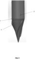
- FIG. 9 shows an enlarged view of the screw tip 13, illustrating drilling threads 33 having a diameter which is substantially the same as the diameter t of the second portion 28.
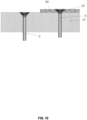
- FIG. 10 illustrates the screw 10 during use for fastening a metal bracket 202 to a wooden part 201. It is envisaged that the screw 10 may be used to fasten other parts together, for example two or more wooden parts, or two or more metal parts.
- the metal bracket 202 has a hole 203 that is arranged to receive a countersunk screw.
- the metal bracket 202 is placed on top of a wooden part 201, and the screw 10 is inserted firstly through the metal bracket 202 and subsequently into the wooden part 201 from the tip 13 end.
- the screw 10 When the screw 10 is fully inserted, the head 11 of the screw 10 is received within the hole 203 of the metal bracket 202, which prevents the head 11 of the screw 10 from being inserted further into the metal bracket 202.
- the ribs 21 engage with the metal bracket 202 and the head 11 of the screw 10 rests in the part of the bracket 202 that is countersunk by 90 degrees.
- the ribs 21 are prevented from milling into the bracket 202 due to the shape of the frustoconical portion 16.
- the first frustoconical part 19 shields the ribs 21 against milling the bracket 202.
- the screw 10 is provided with improved engagement and pull-out resistance through the ribs, and the ribs 21 are prevented from milling into the part to be fixated upon insertion and rotation.
- FIG. 11, FIG. 12 and FIG. 13 shows another example of a screw head 111.
- the screw head 111 differs from the screw head 11 of FIG. 2 and FIG. 3 in that the ribs 121 are symmetrical with respect to an axial plane containing their axial edge 122.
- the size of the first face 123 and the size of the second face 124 of the ribs 121 are the same. This is in contrast with the asymmetrical arrangement of the ribs 21 in FIG. 2 and FIG. 3 .
Landscapes
- Engineering & Computer Science (AREA)
- General Engineering & Computer Science (AREA)
- Mechanical Engineering (AREA)
- Physics & Mathematics (AREA)
- Geometry (AREA)
- Life Sciences & Earth Sciences (AREA)
- Chemical & Material Sciences (AREA)
- Dispersion Chemistry (AREA)
- Wood Science & Technology (AREA)
- Connection Of Plates (AREA)
Abstract
Description
- The present invention relates to a screw.
- Fasteners may be used to fasten two or more parts together. For example, a fastener may be used to fasten a metal bracket to a wooden part, or to fasten two metal parts together, or two wooden parts together.
- One example of a fastener is a screw. Screws have been known and available for many years, and are generally made of metal and include a shank having a head at one end, and a tip at an opposite end to the head.
- One known problem with existing screws is that once inserted into the two or more parts to hold them together, they can become loosened due to vibrations, frequent use, or corrosion (e.g. weathering), for example, which negatively affects the fixation of the parts. Another known problem with existing screws is low pull-out resistance, which causes instability, breakage, damage and collapse of structures under load.
- The present invention aims to overcome these disadvantages. In particular, it is an object of the present invention to provide a screw with improved pull-out resistance, in order to provide improved fixation. It is another object of the present invention to provide a screw that is less susceptible to loosening once inserted.
- The invention is defined in the appended claims.
- According to an aspect, there is provided a screw, comprising a head and a tip at opposite ends, and a shank extending between the head and the tip, the head comprising: a top portion, and a frustoconical portion arranged between the top portion and the shank, wherein the frustoconical portion comprises a step defining an annular recess towards the shank; and at least one radial rib arranged in the recess and extending towards the shank.
- By providing at least one radial rib that is arranged within an annular recess defined by a step of a frustoconical portion, the rib(s) engage with the part to be fixated, which improves pull-out resistance and therefore provides improved fixation. Even when the part vibrates, corrodes, or is otherwise moved, the head of the screw remains fixed to the part via the rib(s), improving contact between the screw and the part to be fixated. This allows the screw to be more firmly held during use, making the screw less susceptible to loosening. Another advantage of having at least one radial rib extending towards the shank and arranged within the recess defined by a step in the frustoconical portion is that the frustoconical portion shields the radial rib(s) from milling the part to be fixated upon insertion and rotation of the screw.
- In examples, the frustoconical portion comprises a circumferential surface facing the shank and the tip. In examples, the circumferential surface is arranged substantially perpendicular to an axis of the screw.
- In examples, step segments the frustoconical portion into a first frustoconical part extending from the top portion to the step, and a second frustoconical part extending from the step towards the shank. In examples, a diameter of the first frustoconical part is greater than a diameter of the second frustoconical part.
- In examples, the head of the screw comprises a plurality of ribs evenly distributed around the head. This is particularly advantageous because the ribs uniformly contact the part to be fixated and there is provided multiple points of contact between the screw and the part.
- In examples, the, or each, rib has a radial dimension that decreases towards the shank.
- In examples, the, or each, rib comprises an axial edge, the, or each, rib being symmetrical with respect to an axial plane containing the axial edge.
- In examples, the shank comprises a first portion having a first thread, and a second portion between the first portion and the tip, the second portion having a second thread. In examples, the first thread and the second thread are orientated in opposing turning directions.
- In examples, the second thread has a thread angle that is larger than a thread angle of the first thread.
- In examples, the shank comprises a thread comprising a first part, and a second part arranged between the first part and the tip.
- In examples, a thread angle of the thread increases continuously from the first part to the second part.
- In other examples, a thread angle of the thread is constant along the first part and/or the second part.
- In examples, a length of the second part is at least twice the diameter of the shank. In examples, the length of the second part is between two and four times the diameter of the shank.
- According to another aspect, there is provided a screw, comprising a head and a tip at opposite ends, and a shank extending between the head and the tip, wherein the shank comprises at least one drilling thread configured for cutting into wood.
- In examples, a diameter of the at least one drilling thread is substantially equal to a diameter of the shank.
- According to a further aspect, there is provided a screw, comprising a head and a tip at opposite ends, and a shank extending between the head and the tip, wherein the shank comprises a main screw thread, and the tip comprises a drilling thread configured for cutting into wood.
- In examples, the main screw thread extends towards the tip. In examples, the main screw thread extends along the tip. In examples, the main screw thread partially extends along the tip. In other examples, the main screw thread extends along the entire tip.
- In examples, the at least one drilling thread has a pitch that is greater than a pitch of the main screw thread.
- In examples, an external diameter of the at least one drilling thread is smaller than an externa diameter of the main screw thread.
- In other examples, an external diameter of the at least one drilling thread is substantially equal to the diameter of the shank. In examples, an external diameter of the at least one drilling thread is equal to the diameter of the shank with a tolerance t. In examples, the tolerance t may be of +0.0 to +0.5mm, preferably +0.0 to +0.2mm.
- In examples, the tip comprises a plurality of drilling threads. In examples, the plurality of drilling threads are regularly distributed around the tip. This advantageously provides multiple points of cutting.
- In examples, the head comprises: a top portion, and a frustoconical portion arranged between the top portion and the shank, wherein the frustoconical portion comprises a step defining an annular recess towards the shank; and at least one radial rib arranged in the recess and extending towards the shank.
- By providing at least one radial rib that is arranged within an annular recess defined by a step of a frustoconical portion, the rib(s) engage with the part to be fixated, which improves pull-out resistance and therefore provides improved fixation. Even when the part vibrates, corrodes, or is otherwise moved, the head of the screw remains fixed to the part via the rib(s), improving contact between the screw and the part to be fixated. This allows the screw to be more firmly held during use, making the screw less susceptible to loosening. Another advantage of having at least one radial rib extending towards the shank and arranged within the recess defined by a step in the frustoconical portion is that the frustoconical portion shields the radial rib(s) from milling the part to be fixated upon insertion and rotation of the screw
- In examples, the frustoconical portion comprises a circumferential surface facing the shank and the tip.
- In examples, the circumferential surface is arranged substantially perpendicular to an axis of the screw.
- In examples, the step segments the frustoconical portion into a first frustoconical part extending from the top portion to the step, and a second frustoconical part extending from the step towards the shank.
- In examples, a diameter of the first frustoconical part is greater than a diameter of the second frustoconical part.
- In examples, the head of the screw comprises a plurality of ribs evenly distributed around the head. The provision of a plurality of ribs further increases pull-out resistance and improve fixation.
- In examples, the, or each, rib has a radial dimension that decreases towards the shank.
- In examples, the, or each, rib comprises an axial edge, the, or each, rib being symmetrical with respect to an axial plane containing the axial edge.
- In other examples, the, or each, rib is asymmetrical with respect to an axial plane containing the axial edge.
- In examples, the shank comprises a first portion having a first thread, and a second portion between the first portion and the tip, the second portion having a second thread. In examples, the first thread and the second thread are orientated in opposing turning directions.
- In examples, the second thread has a thread angle that is larger than a thread angle of the first thread.
- In examples, the thread of the shank comprises a first part, and a second part arranged between the first part and he tip.
- In examples, a thread angle of the thread increases continuously from the first part to the second part.
- In other examples, a thread angle of the thread is constant along the first part and/or the second part.
- In examples, a length of the second part and the tip is at least twice the diameter of the shank. In examples, a length of the second part and the tip is between two and four times the diameter of the shank.
- In examples, a combined length of the second part and the tip is at least twice the diameter of the shank. In examples, a combined length of the second part and the tip is between two and four times the diameter of the shank.
- According to another aspect, there is provided a screw, comprising a head and a tip at opposite ends, and a shank extending between the head and the tip, wherein the shank comprises a thread comprising a first part, and a second part arranged between the first part and the tip, wherein a thread angle of the second part is greater than a thread angle of the first part.
- In examples, the thread angle of the second part is between 5 and 15 degrees greater than the thread angle of the first part. In examples, the thread angle of the second part is 10 degrees greater than the thread angle of the first part.
- According to a further aspect, there is provided a screw, comprising a head and a tip at opposite ends, and a shank extending between the head and the tip, wherein the shank comprises a thread comprising a first part, and a second part arranged between the first part and the tip, wherein a length of the second part and the tip is at least twice the diameter of the shank. In examples, the combined length of the second part and the tip is at least twice the diameter of the shank.
- In examples, the length of the second part and the tip is between two and four times the diameter of the shank. In examples, the combined length of the second part and the tip is between two and four times the diameter of the shank.
- In examples, the screw is a wood screw.
- In examples, the screw has a head and a shank axially prolonging the head until a free end or tip.
- In examples, the head has a top portion. The top portion may be substantially cylindrical. The top portion may have a top surface. The top surface may be flat, or raised (e.g., oval). The top surface may have a tool socket.
- In examples, the head has a substantially frustoconical or tulip-shape portion arranged between the top portion and the shank. The diameter of the frustoconical portion may decrease from the top portion to the shank.
- In examples, the frustoconical portion has a step or shoulder defining an annular recess towards the shank and/or a circumferential surface facing the shank and the tip. The surface may be substantially perpendicular to the axis of the screw. The surface may be substantially flat. The step may divide the frustoconical portion into a first frustoconical part and a second frustoconical part. The first frustoconical part may extend from the top portion to the step. The second frustoconical part may extend from the step towards the shank. The frustoconical portion may have a greater diameter between the step and the top portion (at the first frustoconical part) than between the step and the shank (at the second frustoconical part).
- In examples, the head has at least one rib. The rib(s) may be radial. The rib(s) may be oriented axially. The rib(s) may be regularly distributed around the head. The rib(s) may be in the annular recess. The rib(s) may extend from the surface towards the shank. A radial dimension of the rib(s) may decrease from the surface towards the shank. The rib(s) may have a substantially pyramidal shape. The rib(s) may have an axial edge. The rib(s) may be asymmetrical with respect to an axial plane containing their axial edge. The axial edge may be common to a first face oriented towards a first direction of rotation and an opposite second face. The second face may be larger than the first face. The first direction of rotation may be to the left, when the screw is viewed with the head up. The maximum diameter of the rib(s) may be substantially equal to the maximal diameter of the head at the step.
- In examples, the head has at least one axial notch. The notch(es) may be U-shaped. The notch(es) may extend at least partially along the top portion and/or along the frustoconical portion. The notch(es) may extend along the first frustoconical part. The notch(es) may be axially aligned with the rib(s) . The notch(es) may be made for air and/or oil passage when realizing the rib(s).
- In examples, the shank has a first portion. The first portion may have a first thread. The first thread may turn right towards the tip, when the screw is viewed with the head up.
- In examples, the shank has a second portion. The second portion may be between the first portion and the tip.
- In examples, the second portion has a second thread. The second thread may turn left towards the tip, when the screw is viewed with the head up. The second thread may continue along the tip. The second thread may have a thread angle α that is larger at a first part of the second thread than at a second part of the second thread. The second part may be closer to the tip than the first part. The thread angle α may be constant along the first part. The thread angle α may be constant along the second part. The thread angle α may increase from the first part to the second part. The thread angle α may continuously and regularly increase from the first part to the second part. The thread angle α may increase by approximatively 10° from the first part to the second part. The thread angle α may be equal at the second part and at the tip. The length L of the second part and the tip along the axis of the screw may be equal to at least twice the diameter of the second portion (i.e. shank). The length L may be equal to two to four times the diameter of the second portion.
- In examples, the second thread has axial notches or cuts at an area close to the tip. The notches may be V-shaped. The notches may be regularly distributed around the second portion. The notches may define spikes or peaks or teeth along the second thread. The notches may be axially aligned.
- In examples, the shank has a third portion. The third portion may be between the head and the first portion. The third portion may have no thread.
- In examples, the tip has at least one drilling or cutting thread. The drilling threads may be regularly distributed around the tip. The drilling threads may be completely or almost completely located at the tip. The drilling threads may turn left away from the shank, when the screw is viewed with the head up. The pitch of the drilling threads may be greater than the pitch of the second thread. The external diameter of the drilling threads may be inferior to the external diameter of the second thread. The drilling threads may have a diameter which is substantially equal to the diameter of the second portion. The diameter of the drilling threads may be equal to the diameter of the second portion with a tolerance t. The tolerance t may be of +0.0 to +0.5mm, preferably +0.0 to +0.2mm. The tip may be pointed.
- In examples, the screw is used for fastening wooden parts together. The screw may also, or alternatively, be used for fastening a metal bracket having a hole designed to receive a countersunk screw, for example a 90° countersunk screw, to wooden part(s), the head of the screw being received in said hole.
- Embodiments of the invention are now described, by way of example only, hereinafter with reference to the accompanying drawings.
-
FIG. 1 illustrates a perspective view of a screw. -
FIG. 2 illustrates an enlarged perspective view of a screw head. -
FIG. 3 illustrates a profile side view of the screw head. -
FIG. 4 illustrates a profile side view of a screw tip. -
FIG. 5 illustrates the screw viewed from the tip. -
FIG. 6 illustrates an enlarged perspective view of a first portion of the screw. -
FIG. 7 illustrates an enlarged perspective view of the screw head. -
FIG. 8 illustrates a partial section view of a second portion of the screw, and a detail view of first and second thread parts. -
FIG. 9 illustrates an enlarged perspective view of the screw tip. -
FIG. 10 illustrates an application of the screw to assemble two parts together. -
FIG. 11 illustrates a perspective view of another screw head. -
FIG. 12 illustrates a profile side view of the screw head, viewed from a first side. -
FIG. 13 illustrates a profile side view of the screw head, viewed from a second side. - Certain terminology is used in the following description for convenience only and is not limiting. The words 'right', 'left', 'lower', 'upper', 'front', 'rear', 'upward', 'down' and 'downward' designate directions in the drawings to which reference is made and are with respect to the described component when assembled and mounted. The words 'inner', `inwardly', `outer' and 'outwardly' refer to directions toward and away from, respectively, a designated centreline or a geometric centre of an element being described (e.g. central axis), the particular meaning being readily apparent from the context of the description.
- Further, as used herein, the terms 'connected', 'attached', 'coupled' and 'mounted' are intended to include direct connections between two members without any other members interposed therebetween, as well as, indirect connections between members in which one or more other members are interposed therebetween. The terminology includes the words specifically mentioned above, derivatives thereof, and words of similar import.
- Further, unless otherwise specified, the use of ordinal adjectives, such as, "first", "second" and "third" etc. merely indicate that different instances of like objects are being referred to and are not intended to imply that the objects so described must be in a given sequence, either temporally, spatially, in ranking or in any other manner.
- Like reference numerals are used to depict like features throughout.
-
FIG. 1 shows a perspective view of ascrew 10. In this example, thescrew 10 is a wood screw. Thescrew 10 has ahead 11 and atip 13 at opposite ends, and ashank 12 extending between thehead 11 and thetip 13. Theshank 12 includes amain screw thread 29. In this example, themain screw thread 29 extends along thetip 13. Thetip 13 includes at least onedrilling thread 33. The at least onedrilling thread 33 may be configured for cutting into wood. Theshank 12 axially prolongs the head until it reaches thetip 13 at a free end. Theshank 12 in this example has three portions: afirst portion 26 at a central region in theshank 12; asecond portion 28 between thefirst portion 26 and thetip 13; and athird portion 32 between thehead 11 and thefirst portion 26 and having no thread. Although in this example theshank 12 has three portions, it is envisaged that theshank 12 may instead include a single portion having themain screw thread 29. For example, theshank 12 may be provided with a main screw thread 29 (e.g. at the second portion 28), without thefirst portion 26 and without thethird portion 32. Themain screw thread 29 may extend the entire length of theshank 12. In other examples, themain screw thread 29 may extend only partially along the length of theshank 12. Themain screw thread 29 may extend towards the tip. In examples, the main screw thread extends along the tip. In examples, the main screw thread partially extends along the tip. In other examples, the main screw thread extends along the entire tip. -
FIG. 2 andFIG. 3 show an enlarged view of thehead 11. Thehead 11 includes atop portion 14, which is substantially cylindrical in this example. Thetop portion 14 is provided with atop surface 15. Thetop surface 15 is flat in this example, although it is envisaged that in other examples thetop surface 15 may be raised. Thetop surface 15 of thehead 11 is provided with atool socket 151 which is shaped and configured for the insertion of a tool (not shown). - The
head 11 has a substantially frustoconical portion 16 (i.e. tulip-shaped portion) arranged between thetop portion 14 and theshank 12. The diameter of thefrustoconical portion 16 decreases from thetop portion 14 towards theshank 12. Thefrustoconical portion 16 is provided with a step 17 (i.e. shoulder) that defines an annular recess (50,FIG. 5 ) towards theshank 12. In this example, thefrustoconical portion 16 includes acircumferential surface 18 that faces theshank 12 and thetip 13. Thecircumferential surface 18 is substantially perpendicular to the axis of thescrew 10, and is a substantially flat surface. - The
step 17 of thefrustoconical portion 16 divides thefrustoconical portion 16 into a firstfrustoconical part 19 and a secondfrustoconical part 20. The firstfrustoconical part 19 extends from thetop portion 14 to thestep 17, while the secondfrustoconical part 20 extends from thestep 17 towards theshank 12. The diameter at the firstfrustoconical part 19 is greater than the diameter at the secondfrustoconical part 20. - The
head 11 includes at least oneradial rib 21. In this example, thehead 11 is provided with sixradial ribs 21, although only threeribs 21 are illustrated in the view ofFIG. 2 . Theribs 21 are oriented axially, and are regularly distributed around thehead 11. Theribs 21 are located within the annular recess (50,FIG. 5 ). In this example, theribs 21 extend from thecircumferential surface 18 towards theshank 12. A radial dimension of theribs 21 decreases from thesurface 18 towards theshank 12, such that theribs 21 have a substantially pyramidal shape. Theribs 21 are provided with anaxial edge 22. In this example, theribs 21 are arranged asymmetrically with respect to an axial plane containing theaxial edge 22. Theaxial edge 22 in this example is common to afirst face 23 oriented towards a first direction of rotation and an oppositesecond face 24. The first direction of rotation may be to the left, when thescrew 10 is viewed with thehead 11 up. Thesecond face 24 is larger than thefirst face 23. The maximum diameter of theribs 21 is substantially equal to the maximum diameter of thehead 11 at thestep 17. -
FIG. 4 shows thetip 13 end of thescrew 10, which illustrates a second thread 29 (i.e. main screw thread) of thesecond portion 28. Thesecond thread 29 turns left towards thetip 13, when thescrew 10 is viewed with thehead 11 up. Thesecond thread 29 continues along thetip 13. Thesecond thread 29 includes axial notches 30 (i.e. cuts) at an area close to thetip 13. Thenotches 30 are V-shaped in this example. Thenotches 30 are regularly distributed around thesecond portion 28. Thenotches 30 define teeth 31 (e.g. spikes or peaks) along thesecond thread 29. In this example, thenotches 30 are axially aligned. - The
tip 13 is pointed and includes at least one drilling thread 33 (i.e. cutting thread). In this example, thetip 13 includes a plurality ofdrilling threads 33 that are regularly distributed around thetip 13. Thedrilling threads 33 are located either completely or almost completed at thetip 13. Thedrilling threads 33 are arranged to turn left away from theshank 12, when thescrew 10 is viewed with thehead 11 up. - As illustrated, the pitch of the
drilling threads 33 are greater than the pitch of thesecond thread 29. The external diameter of thedrilling threads 33 are smaller in comparison to the external diameter of thesecond threads 29. For example, the diameter of the drilling threads is equal to the diameter of thesecond portion 28 with a tolerance t, which may be +0.0 to +0.5mm, preferably +0.0 to +0.2mm. -
FIG. 5 shows thescrew 10 viewed from thetip 13 end. As shown, thehead 11 of thescrew 10 has astep 17 defining anannular recess 50, in which sixradial ribs 21 are disposed and extend towards theshank 12. -
FIG. 6 shows thefirst portion 26 of theshank 12 at a central region which is between thesecond portion 28 and thethird portion 32. Thefirst portion 26 is provided with afirst thread 27. Thefirst thread 27 turns right towards thetip 13, when thescrew 10 is viewed with thehead 11 up. As such, thefirst thread 27 and thesecond thread 29 are orientated in opposing turning directions from one another. -
FIG. 7 shows a portion of thescrew head 11. In this example, thehead 11 of the screw is provided with at least oneaxial notch 25, which is U-shaped. The, or each, notch 25 extends at least partially along thetop portion 14. In other examples, the, or each, notch 25 extends at least partially along the firstfrustoconical part 19. Thenotches 25 are axially aligned with therespective ribs 21. Thenotches 25 facilitate the passage of fluids such as air and/or oil. - The second thread (i.e. main screw thread) 29 will now be described in more detail with reference to
FIG. 8 . Thesecond thread 29 has afirst part 291 proximal thehead 11 and asecond part 292 between thefirst part 291 and thetip 13. Thesecond thread 29 has a thread angle α that is larger at thefirst part 291 than at thesecond part 292. In some examples, the thread angle α is constant along thefirst part 291. In some examples, the thread angle α is constant along thesecond part 292. In some examples, the thread angle α may increase from thefirst part 291 of thesecond thread 29 to thesecond part 292 of thesecond thread 29. The thread angle α may continuously and regularly increase from thefirst part 291 to thesecond part 292. For example, the thread angle α may increase by approximately 10 degrees from thefirst part 291 to thesecond part 292. The thread angle α may be equal at thesecond part 292 and at thetip 13. In this example, the combined length L of thesecond part 292 and thetip 13 along the axis of thescrew 10 is equal to at least twice the diameter of thesecond portion 28. In particular, the length L may be equal to two to four times the diameter of thesecond portion 28. -
FIG. 9 shows an enlarged view of thescrew tip 13, illustratingdrilling threads 33 having a diameter which is substantially the same as the diameter t of thesecond portion 28. -
FIG. 10 illustrates thescrew 10 during use for fastening ametal bracket 202 to a wooden part 201. It is envisaged that thescrew 10 may be used to fasten other parts together, for example two or more wooden parts, or two or more metal parts. As shown, themetal bracket 202 has ahole 203 that is arranged to receive a countersunk screw. To fixate themetal bracket 202 to a wooden part 201, themetal bracket 202 is placed on top of a wooden part 201, and thescrew 10 is inserted firstly through themetal bracket 202 and subsequently into the wooden part 201 from thetip 13 end. When thescrew 10 is fully inserted, thehead 11 of thescrew 10 is received within thehole 203 of themetal bracket 202, which prevents thehead 11 of thescrew 10 from being inserted further into themetal bracket 202. When thescrew 10 is inserted, theribs 21 engage with themetal bracket 202 and thehead 11 of thescrew 10 rests in the part of thebracket 202 that is countersunk by 90 degrees. However, theribs 21 are prevented from milling into thebracket 202 due to the shape of thefrustoconical portion 16. In particular, the firstfrustoconical part 19 shields theribs 21 against milling thebracket 202. As such, thescrew 10 is provided with improved engagement and pull-out resistance through the ribs, and theribs 21 are prevented from milling into the part to be fixated upon insertion and rotation. -
FIG. 11, FIG. 12 and FIG. 13 shows another example of ascrew head 111. Thescrew head 111 differs from thescrew head 11 ofFIG. 2 andFIG. 3 in that theribs 121 are symmetrical with respect to an axial plane containing theiraxial edge 122. Thus, the size of thefirst face 123 and the size of thesecond face 124 of theribs 121 are the same. This is in contrast with the asymmetrical arrangement of theribs 21 inFIG. 2 andFIG. 3 . - It will be appreciated by persons skilled in the art that the above detailed examples have been described by way of example only and not in any limitative sense, and that various alterations and modifications are possible without departing from the scope of the invention as defined by the appended claims. Various modifications to the detailed examples described above are possible.
- Through the description and claims of this specification, the words "comprise" and "contain" and variations of them mean "including but not limited to", and they are not intended to (and do not) exclude other moieties, additives, components, integers or steps. Throughout the description and claims of this specification, the singular encompasses the plural unless the context otherwise requires. In particular, where the indefinite article is used, the specification is to be understood as contemplating plurality as well as singularity, unless the context requires otherwise.
- Features, integers, characteristics, compounds, chemical moieties or groups described in conjunction with a particular aspect, embodiment or example of the invention are to be understood to be applicable to any other aspect, embodiment or example described herein unless incompatible therewith. All of the features disclosed in this specification (including any accompanying claims, abstract and drawings), and/or all of the steps of any method or process so disclosed, may be combined in any combination, except combinations where at least some of such features and/or steps are mutually exclusive. The invention is not restricted to the details of any foregoing embodiments. The invention extends to any novel one, or any novel combination, of the features disclosed in this specification (including any accompanying claims, abstract or drawings), or to any novel one, or any novel combination, of the steps of any method or process so disclosed.
- It will be appreciated by persons skilled in the art that the above embodiment(s) have been described by way of example only and not in any limitative sense, and that various alterations and modifications are possible without departing from the scope of the invention as defined by the appended claims. Various modifications to the detailed designs as described above are possible.
Claims (15)
- A screw, comprising a head and a tip at opposite ends, and a shank extending between the head and the tip, the head comprising:a top portion, and a frustoconical portion arranged between the top portion and the shank, wherein the frustoconical portion comprises a step defining an annular recess towards the shank; andat least one radial rib arranged in the recess and extending towards the shank.
- A screw of claim 1, wherein the frustoconical portion comprises a circumferential surface facing the shank and the tip.
- A screw of claim 2, wherein the circumferential surface is arranged substantially perpendicular to an axis of the screw.
- A screw of any one of claims 1 to 3, wherein the step segments the frustoconical portion into a first frustoconical part extending from the top portion to the step, and a second frustoconical part extending from the step towards the shank.
- A screw of claim 4, wherein a diameter of the first frustoconical part is greater than a diameter of the second frustoconical part.
- A screw of any one of claims 1 to 5, wherein the head of the screw comprises a plurality of ribs evenly distributed around the head.
- A screw of any one of claims 1 to 6, wherein the, or each, rib has a radial dimension that decreases towards the shank.
- A screw of any one of claims 1 to 7, wherein the, or each, rib comprises an axial edge, the, or each, rib being symmetrical with respect to an axial plane containing the axial edge.
- A screw of any one of claims 1 to 8, wherein the shank comprises a first portion having a first thread, and a second portion between the first portion and the tip, the second portion having a second thread.
- A screw of claim 9, wherein the first thread and the second thread are orientated in opposing turning directions.
- A screw of claim 9 or 10, wherein the second thread has a thread angle that is larger than a thread angle of the first thread.
- A screw of any one of claims 1 to 11, wherein the shank comprises a thread comprising a first part, and a second part arranged between the first part and the tip.
- A screw of claim 12, wherein a thread angle of the thread increases continuously from the first part to the second part.
- A screw of claim 12, wherein a thread angle of the thread is constant along the first part and/or the second part.
- A screw of any one of claims 12 to 14, wherein a length of the second part and the tip is at least twice the diameter of the shank, preferably between two and four times the diameter of the shank.
Priority Applications (2)
| Application Number | Priority Date | Filing Date | Title |
|---|---|---|---|
| US18/392,577 US20240209889A1 (en) | 2022-12-22 | 2023-12-21 | Wood screw |
| AU2023285839A AU2023285839A1 (en) | 2022-12-22 | 2023-12-21 | Screw |
Applications Claiming Priority (1)
| Application Number | Priority Date | Filing Date | Title |
|---|---|---|---|
| EP22216153 | 2022-12-22 |
Publications (1)
| Publication Number | Publication Date |
|---|---|
| EP4390157A1 true EP4390157A1 (en) | 2024-06-26 |
Family
ID=84569284
Family Applications (1)
| Application Number | Title | Priority Date | Filing Date |
|---|---|---|---|
| EP23218519.9A Pending EP4390157A1 (en) | 2022-12-22 | 2023-12-20 | Screw |
Country Status (3)
| Country | Link |
|---|---|
| US (1) | US20240209889A1 (en) |
| EP (1) | EP4390157A1 (en) |
| AU (1) | AU2023285839A1 (en) |
Families Citing this family (1)
| Publication number | Priority date | Publication date | Assignee | Title |
|---|---|---|---|---|
| USD996962S1 (en) * | 2020-11-17 | 2023-08-29 | National Nail Corp. | Screw |
Citations (5)
| Publication number | Priority date | Publication date | Assignee | Title |
|---|---|---|---|---|
| US5203657A (en) * | 1991-05-29 | 1993-04-20 | Topura Co., Ltd. | Self-tapping screw |
| EP3249244A1 (en) * | 2016-05-27 | 2017-11-29 | Kuo-Tai Hsu | Screw |
| US10436238B2 (en) * | 2016-04-04 | 2019-10-08 | The Hillman Group, Inc. | Screw type fastener |
| US20190390700A1 (en) * | 2018-06-25 | 2019-12-26 | The Hillman Group, Inc. | Screw-type fastener for cement board |
| WO2021001192A1 (en) * | 2019-07-03 | 2021-01-07 | Hilti Aktiengesellschaft | Dry-construction screw |
Family Cites Families (6)
| Publication number | Priority date | Publication date | Assignee | Title |
|---|---|---|---|---|
| WO2019199430A1 (en) * | 2018-04-09 | 2019-10-17 | The Hillman Group, Inc. | Screw-type fastener for concrete and hurricane resistance applications |
| US11572915B2 (en) * | 2018-06-25 | 2023-02-07 | The Hillman Group, Inc. | Screw-type fastener for cement board |
| USD1012685S1 (en) * | 2020-02-11 | 2024-01-30 | B.M.B. Investments Pty Ltd | Screw |
| US11598363B2 (en) * | 2020-09-23 | 2023-03-07 | Bi-Mirth Corp. | Low-wear screw structure |
| US12085107B2 (en) * | 2021-03-30 | 2024-09-10 | The Hillman Group, Inc. | Structural screw |
| US12369959B2 (en) * | 2022-12-16 | 2025-07-29 | Primesource Building Products, Inc. | Screw with an improved screw head |
-
2023
- 2023-12-20 EP EP23218519.9A patent/EP4390157A1/en active Pending
- 2023-12-21 US US18/392,577 patent/US20240209889A1/en active Pending
- 2023-12-21 AU AU2023285839A patent/AU2023285839A1/en active Pending
Patent Citations (5)
| Publication number | Priority date | Publication date | Assignee | Title |
|---|---|---|---|---|
| US5203657A (en) * | 1991-05-29 | 1993-04-20 | Topura Co., Ltd. | Self-tapping screw |
| US10436238B2 (en) * | 2016-04-04 | 2019-10-08 | The Hillman Group, Inc. | Screw type fastener |
| EP3249244A1 (en) * | 2016-05-27 | 2017-11-29 | Kuo-Tai Hsu | Screw |
| US20190390700A1 (en) * | 2018-06-25 | 2019-12-26 | The Hillman Group, Inc. | Screw-type fastener for cement board |
| WO2021001192A1 (en) * | 2019-07-03 | 2021-01-07 | Hilti Aktiengesellschaft | Dry-construction screw |
Also Published As
| Publication number | Publication date |
|---|---|
| US20240209889A1 (en) | 2024-06-27 |
| AU2023285839A1 (en) | 2024-07-11 |
Similar Documents
| Publication | Publication Date | Title |
|---|---|---|
| US10724566B2 (en) | Threaded fastener | |
| CA2236947C (en) | Fastener | |
| US10309437B2 (en) | Screw | |
| US5827030A (en) | Thread forming joining elements | |
| US8118849B2 (en) | Bone screw with selectively securable washer | |
| US9119674B2 (en) | Bone anchoring device | |
| CN104507405B (en) | bone fixation device | |
| TWI755590B (en) | Screw-type fastener for concrete and hurricane resistance applications | |
| JP4225546B2 (en) | Tapping screw | |
| CA3072757C (en) | Sheet metal screw | |
| US20100076496A1 (en) | Variable Angle Locked Bone Fixation System | |
| KR20070006596A (en) | Bone fixation element | |
| KR102690434B1 (en) | Thread forming and thread locking fasteners | |
| JP7789123B2 (en) | Variable angle locking structure for orthopedic applications | |
| KR20160014602A (en) | Screw | |
| US20110255936A1 (en) | Threaded Fastener | |
| KR20130139960A (en) | Threaded fastener | |
| EP3399200B1 (en) | Screw for thin iron sheets | |
| US20240209889A1 (en) | Wood screw | |
| JPH11351221A (en) | Screw fastener preventing oblique screw-in | |
| US20250075721A1 (en) | Drywall anchor and method for installing a drywall anchor | |
| JP2002153479A (en) | Bone screw | |
| TWI626383B (en) | Screw | |
| FI94078C (en) | Expanding plug | |
| KR101334520B1 (en) | Head detachable cutting tool, cutting head and holder |
Legal Events
| Date | Code | Title | Description |
|---|---|---|---|
| PUAI | Public reference made under article 153(3) epc to a published international application that has entered the european phase |
Free format text: ORIGINAL CODE: 0009012 |
|
| STAA | Information on the status of an ep patent application or granted ep patent |
Free format text: STATUS: THE APPLICATION HAS BEEN PUBLISHED |
|
| AK | Designated contracting states |
Kind code of ref document: A1 Designated state(s): AL AT BE BG CH CY CZ DE DK EE ES FI FR GB GR HR HU IE IS IT LI LT LU LV MC ME MK MT NL NO PL PT RO RS SE SI SK SM TR |
|
| STAA | Information on the status of an ep patent application or granted ep patent |
Free format text: STATUS: REQUEST FOR EXAMINATION WAS MADE |
|
| 17P | Request for examination filed |
Effective date: 20241218 |
|
| STAA | Information on the status of an ep patent application or granted ep patent |
Free format text: STATUS: EXAMINATION IS IN PROGRESS |
|
| 17Q | First examination report despatched |
Effective date: 20251031 |