EP4390136A1 - Pump for conveying wastewater and impeller for such a pump - Google Patents
Pump for conveying wastewater and impeller for such a pump Download PDFInfo
- Publication number
- EP4390136A1 EP4390136A1 EP23215858.4A EP23215858A EP4390136A1 EP 4390136 A1 EP4390136 A1 EP 4390136A1 EP 23215858 A EP23215858 A EP 23215858A EP 4390136 A1 EP4390136 A1 EP 4390136A1
- Authority
- EP
- European Patent Office
- Prior art keywords
- impeller
- blade
- passage
- pump
- axial direction
- Prior art date
- Legal status (The legal status is an assumption and is not a legal conclusion. Google has not performed a legal analysis and makes no representation as to the accuracy of the status listed.)
- Pending
Links
- 239000002351 wastewater Substances 0.000 title claims abstract description 25
- 239000007787 solid Substances 0.000 claims description 7
- 239000007788 liquid Substances 0.000 claims description 6
- 239000012530 fluid Substances 0.000 description 13
- 238000004519 manufacturing process Methods 0.000 description 12
- 239000000463 material Substances 0.000 description 6
- 238000005266 casting Methods 0.000 description 5
- 239000000654 additive Substances 0.000 description 4
- 230000000996 additive effect Effects 0.000 description 4
- 239000000835 fiber Substances 0.000 description 4
- 238000003754 machining Methods 0.000 description 3
- 238000000034 method Methods 0.000 description 3
- 238000010146 3D printing Methods 0.000 description 2
- 230000000903 blocking effect Effects 0.000 description 2
- 238000005520 cutting process Methods 0.000 description 2
- 238000003801 milling Methods 0.000 description 2
- 229910001018 Cast iron Inorganic materials 0.000 description 1
- -1 cloths Substances 0.000 description 1
- 238000004891 communication Methods 0.000 description 1
- 230000007423 decrease Effects 0.000 description 1
- 230000001419 dependent effect Effects 0.000 description 1
- 239000010840 domestic wastewater Substances 0.000 description 1
- 238000005553 drilling Methods 0.000 description 1
- 230000002349 favourable effect Effects 0.000 description 1
- 239000002657 fibrous material Substances 0.000 description 1
- 239000010842 industrial wastewater Substances 0.000 description 1
- 238000012423 maintenance Methods 0.000 description 1
- 239000002184 metal Substances 0.000 description 1
- 229910052751 metal Inorganic materials 0.000 description 1
- 238000004088 simulation Methods 0.000 description 1
- 239000004753 textile Substances 0.000 description 1
- 230000007704 transition Effects 0.000 description 1
- XLYOFNOQVPJJNP-UHFFFAOYSA-N water Substances O XLYOFNOQVPJJNP-UHFFFAOYSA-N 0.000 description 1
Images


Classifications
-
- F—MECHANICAL ENGINEERING; LIGHTING; HEATING; WEAPONS; BLASTING
- F04—POSITIVE - DISPLACEMENT MACHINES FOR LIQUIDS; PUMPS FOR LIQUIDS OR ELASTIC FLUIDS
- F04D—NON-POSITIVE-DISPLACEMENT PUMPS
- F04D13/00—Pumping installations or systems
- F04D13/02—Units comprising pumps and their driving means
- F04D13/06—Units comprising pumps and their driving means the pump being electrically driven
- F04D13/08—Units comprising pumps and their driving means the pump being electrically driven for submerged use
-
- F—MECHANICAL ENGINEERING; LIGHTING; HEATING; WEAPONS; BLASTING
- F04—POSITIVE - DISPLACEMENT MACHINES FOR LIQUIDS; PUMPS FOR LIQUIDS OR ELASTIC FLUIDS
- F04D—NON-POSITIVE-DISPLACEMENT PUMPS
- F04D29/00—Details, component parts, or accessories
- F04D29/40—Casings; Connections of working fluid
- F04D29/42—Casings; Connections of working fluid for radial or helico-centrifugal pumps
- F04D29/426—Casings; Connections of working fluid for radial or helico-centrifugal pumps especially adapted for liquid pumps
- F04D29/4293—Details of fluid inlet or outlet
-
- F—MECHANICAL ENGINEERING; LIGHTING; HEATING; WEAPONS; BLASTING
- F04—POSITIVE - DISPLACEMENT MACHINES FOR LIQUIDS; PUMPS FOR LIQUIDS OR ELASTIC FLUIDS
- F04D—NON-POSITIVE-DISPLACEMENT PUMPS
- F04D29/00—Details, component parts, or accessories
- F04D29/18—Rotors
- F04D29/22—Rotors specially for centrifugal pumps
- F04D29/2261—Rotors specially for centrifugal pumps with special measures
- F04D29/2272—Rotors specially for centrifugal pumps with special measures for influencing flow or boundary layer
-
- F—MECHANICAL ENGINEERING; LIGHTING; HEATING; WEAPONS; BLASTING
- F04—POSITIVE - DISPLACEMENT MACHINES FOR LIQUIDS; PUMPS FOR LIQUIDS OR ELASTIC FLUIDS
- F04D—NON-POSITIVE-DISPLACEMENT PUMPS
- F04D29/00—Details, component parts, or accessories
- F04D29/18—Rotors
- F04D29/22—Rotors specially for centrifugal pumps
- F04D29/2238—Special flow patterns
- F04D29/225—Channel wheels, e.g. one blade or one flow channel
-
- F—MECHANICAL ENGINEERING; LIGHTING; HEATING; WEAPONS; BLASTING
- F04—POSITIVE - DISPLACEMENT MACHINES FOR LIQUIDS; PUMPS FOR LIQUIDS OR ELASTIC FLUIDS
- F04D—NON-POSITIVE-DISPLACEMENT PUMPS
- F04D29/00—Details, component parts, or accessories
- F04D29/18—Rotors
- F04D29/22—Rotors specially for centrifugal pumps
- F04D29/2238—Special flow patterns
- F04D29/2255—Special flow patterns flow-channels with a special cross-section contour, e.g. ejecting, throttling or diffusing effect
-
- F—MECHANICAL ENGINEERING; LIGHTING; HEATING; WEAPONS; BLASTING
- F04—POSITIVE - DISPLACEMENT MACHINES FOR LIQUIDS; PUMPS FOR LIQUIDS OR ELASTIC FLUIDS
- F04D—NON-POSITIVE-DISPLACEMENT PUMPS
- F04D29/00—Details, component parts, or accessories
- F04D29/18—Rotors
- F04D29/22—Rotors specially for centrifugal pumps
- F04D29/24—Vanes
- F04D29/242—Geometry, shape
- F04D29/245—Geometry, shape for special effects
-
- F—MECHANICAL ENGINEERING; LIGHTING; HEATING; WEAPONS; BLASTING
- F04—POSITIVE - DISPLACEMENT MACHINES FOR LIQUIDS; PUMPS FOR LIQUIDS OR ELASTIC FLUIDS
- F04D—NON-POSITIVE-DISPLACEMENT PUMPS
- F04D7/00—Pumps adapted for handling specific fluids, e.g. by selection of specific materials for pumps or pump parts
- F04D7/02—Pumps adapted for handling specific fluids, e.g. by selection of specific materials for pumps or pump parts of centrifugal type
- F04D7/04—Pumps adapted for handling specific fluids, e.g. by selection of specific materials for pumps or pump parts of centrifugal type the fluids being viscous or non-homogenous
-
- F—MECHANICAL ENGINEERING; LIGHTING; HEATING; WEAPONS; BLASTING
- F04—POSITIVE - DISPLACEMENT MACHINES FOR LIQUIDS; PUMPS FOR LIQUIDS OR ELASTIC FLUIDS
- F04D—NON-POSITIVE-DISPLACEMENT PUMPS
- F04D29/00—Details, component parts, or accessories
- F04D29/18—Rotors
- F04D29/22—Rotors specially for centrifugal pumps
- F04D29/2261—Rotors specially for centrifugal pumps with special measures
- F04D29/2294—Rotors specially for centrifugal pumps with special measures for protection, e.g. against abrasion
-
- F—MECHANICAL ENGINEERING; LIGHTING; HEATING; WEAPONS; BLASTING
- F04—POSITIVE - DISPLACEMENT MACHINES FOR LIQUIDS; PUMPS FOR LIQUIDS OR ELASTIC FLUIDS
- F04D—NON-POSITIVE-DISPLACEMENT PUMPS
- F04D29/00—Details, component parts, or accessories
- F04D29/18—Rotors
- F04D29/22—Rotors specially for centrifugal pumps
- F04D29/24—Vanes
- F04D29/242—Geometry, shape
-
- F—MECHANICAL ENGINEERING; LIGHTING; HEATING; WEAPONS; BLASTING
- F05—INDEXING SCHEMES RELATING TO ENGINES OR PUMPS IN VARIOUS SUBCLASSES OF CLASSES F01-F04
- F05D—INDEXING SCHEME FOR ASPECTS RELATING TO NON-POSITIVE-DISPLACEMENT MACHINES OR ENGINES, GAS-TURBINES OR JET-PROPULSION PLANTS
- F05D2240/00—Components
- F05D2240/20—Rotors
- F05D2240/30—Characteristics of rotor blades, i.e. of any element transforming dynamic fluid energy to or from rotational energy and being attached to a rotor
Definitions
- the invention relates to a pump for conveying wastewater or liquids containing solids and to an impeller for such a pump according to the preamble of the independent claim of the respective category.
- Such pumps are frequently configured as centrifugal pumps having radial, semi-axial, or axial impellers, with the impeller having only one blade or also a plurality of blades, for example two blades.
- Impellers that are specifically configured for the conveyance of wastewater are for example disclosed in WO 2014/029790 or in WO 2011/042515 . These impellers, which are specifically designed for the conveyance of wastewater perform very well regarding blockage resistance in particular when operated at the best efficiency point (BEP) or in overload conditions, i.e. when the flow rate referred to the flow rate at the BEP is larger than one (q*>1). Under such favorable conditions the impeller functions by creating a high velocity in a region of the suction surface so as to remove blockage such as trapped fibers.
- an impeller for a pump for conveying wastewater comprising a shroud configured to be rotated about an axis of rotation defining an axial direction, and at least one blade for conveying the wastewater, wherein the blade comprises a leading edge, a trailing edge, a pressure side, a suction side and an upper rim, wherein the blade extends from the shroud in the axial direction to the upper rim, wherein the blade extends in a circumferential direction from the leading edge to the trailing edge, wherein the suction side is the radially inner surface of the blade and the pressure side is the radially outer surface of the blade.
- the blade comprises a closed passage extending inside the blade, said passage having an inlet at the pressure side and an outlet at the suction side of the blade.
- closed passage shall be understood as a passage which is completely closed on all sides or along the entire circumference, respectively, so that the inlet and the outlet are the sole openings through which a fluid can enter or leave the passage.
- a jet is created using the pumped medium to disturb any material build-up on the suction side, especially in the region at the leading edge.
- This jet is driven by the pressure differential between a high pressure region at the pressure side of the blade and the low pressure region inboard of the stagnation line at the suction side of the blade.
- the jet created by the closed passage is ideal for low flow conditions where pressure forces become dominant within the pump.
- the pressure differential across the closed passage i.e. the pressure difference between the pressure prevailing at the inlet of the closed passage and the pressure prevailing at the outlet of the closed passage drives the fluid flow through the closed passage, whereas the centrifugal forces will prevent fibers from entering the closed passage.
- the geometry of the closed passage as well as the location of the inlet and the outlet regarding the axial direction can be optimized to ensure an optimal blockage resistance concurrent with a minimized impact on the hydraulic efficiency of the pump.
- the passage is arranged adjacent to the leading edge of the blade to ensure an optimal removal of any blockage build up at the suction side of the blade.
- the blade(s) of an impeller of a pump for conveying wastewater is/are configured with a rounded leading edge and not with a sharp edge. For this configuration the stagnation line at the leading edge is considered as the boundary between the pressure side and the suction side of the blade.
- the inlet of the passage has a cross-sectional area which is different from a cross-sectional area of the outlet of the passage.
- the cross-sectional area of the inlet is larger than the cross-sectional area of the outlet.
- the inlet is arranged perpendicular to the pressure side. This means, that the cross-sectional area through which the fluid enters the closed passage has a normal vector which is perpendicular to the pressure side of the blade.
- the outlet is arranged perpendicular to the suction side. This means, that the cross-sectional area through which the fluid leaves the closed passage has a normal vector which is perpendicular to the suction side of the blade.
- the impeller is configured as a cast impeller.
- a core can be provided in the casting mold as a place holder for the closed passage.
- the impeller by an additive manufacturing process, e.g. by 3D-printing, or by a hybrid manufacturing process comprising both subtractive manufacturing (e.g. machining or milling) and additive manufacturing.
- a pump for conveying wastewater or liquids containing solids is proposed, wherein the pump has an impeller which is configured according to the invention.
- the pump may be configured as a submersible pump.
- Fig. 1 shows in a sectional representation an embodiment of a pump in accordance with the invention which is designated in its entity with reference numeral 1.
- the pump 1 is configured for conveying wastewater or liquids containing solids.
- the pump 1 is configured as a submersible pump.
- the pump 1 includes in a manner known per se a base plate 2, which is fastened to a housing 6 for example by means of a plurality of screws (not shown).
- the pump 1 further comprises an impeller 3 rotatable about an axis of rotation defining an axial direction A.
- the impeller 3 is configured as a centrifugal impeller 3 for conveying the fluid from a suction opening 4 to a discharge opening 5 of the pump 1.
- the suction opening 4 is provided centrally in the base plate 2.
- the impeller 3 rotates, driven for example by an electric motor which is not shown, about the axial direction A, thereby sucks the fluid to be conveyed, that is here the wastewater, through the suction opening 4 and conveys it to the discharge opening 5.
- the impeller 3 is configured as a single blade impeller 3, i.e. the impeller 3 has exactly one blade 8 for conveying the wastewater from the suction opening 4 to the discharge opening 5.
- a known single blade impeller for conveying wastewater is for example disclosed in WO 2011/042515 .
- the impeller 3 is designed with a plurality of blades, for example with exactly two blades for conveying the wastewater or with more than two blades and in particular with three blades.
- a known impeller with a plurality of blades for conveying wastewater is for example disclosed in WO 2014/029790 .
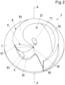
- Fig. 2 shows a perspective view of an embodiment of an impeller in accordance with the invention, wherein the view is from the direction, where the base plate 2 is located in the assembled state of the pump 1.
- Fig. 3 is a plan view of the impeller 3 as seen when looking in the axial direction from the suction opening 4 ( Fig. 1 ) towards the impeller 3.
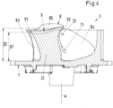
- Fig. 4 is a cross-sectional view of the impeller 3 in a view along the cutting line IV-IV in Fig. 3 .
- the impeller 3 comprises a shroud 7 configured to be rotated about the axis of rotation, i.e. about the axial direction A.
- the shroud 7 comprises a central opening 71 for receiving a drive shaft (not shown), which is connected to the electric motor for driving the rotation of the impeller 3.
- the impeller 3 further comprises the blade 8, which is fixedly connected to the shroud 7.
- the blade 8 comprises a leading edge 81, a trailing edge 82, a pressure side 83, a suction side 84 and an upper rim 85. Regarding the axial direction A the blade 8 extends from the shroud 7 in the axial direction A to the upper rim 85.
- the blade 8 extends from the leading edge 81 spirally outwardly with a changing curvature to the trailing edge 82.
- the leading edge 81 is located radially inwardly from the trailing edge 82, meaning that the leading edge 81 is located closer to the axis of rotation than the trailing edge 82.
- the trailing edge 82 is located at the radially outer rim of the shroud 7.
- the trailing edge 82 slightly overhangs the shroud 7 regarding the radial direction.
- the suction side 84 is the radially inner surface of the blade 8 and the pressure side 83 is the radially outer surface of the blade 8.
- the suction side 84 and the pressure side 83 abut each other at the leading edge 81.
- the leading edge 81 is preferably configured as a rounded region rather than a sharp edge.
- the transition from the pressure side 83 to the suction side 84 is located at the stagnation line S, thus the pressure side 83 is located at the high pressure side of the stagnation line S and the suction side 84 is located at the low pressure side of the stagnation line S.
- the upper rim 85 of the blade is the boundary surface of the blade 8 remote from the shroud 7 and extending in the direction of the longitudinal extent of the blade 8.
- the upper rim 85 is thus that boundary surface of the blade 8 which faces the base plate 2 in the assembled state of the pump 1.
- the upper rim 85 is configured with a changing width as measured perpendicular to the axial direction A. When moving from the leading edge 81 along the upper rim 85 towards the trailing edge 82, the width of the upper rim 85 firstly increases, reaches a maximum and then decreases to a value at the trailing edge 82, which is considerably smaller than the width at the leading edge 81.
- the blade 8 is formed integrally as one piece with the shroud 7.
- the entire impeller 3 is cast of metal, for example cast iron, although any other suitable material may be used.
- the fluid is drawn through the suction opening 4 ( Fig. 1 ) into the impeller 3 and then discharged from the impeller 3 through the channel defined between the leading edge 81 and the trailing edge 82. Said channel is delimited by the suction side 84 of the blade 8.
- the suction side 84 has a sloping profile such as to define a path through the impeller 3 which extends helically downward from the upper rim 85 to the shroud 7. Referring in particular to Fig. 1 and Fig. 4 it can be seen that providing this helical path through the impeller 3 requires a significant infill 31 directly above the shroud 7 (regarding the representation in Fig. 4 ).
- the infill 31 eliminates dead space within the impeller 3 which could give rise to clogging.
- the helical path is achieved by sloping the suction side 84 of the blade 8 radially inwardly from the upper rim 85, in particular in the region adjacent to the leading edge 81, with the slope of the suction side 84 reducing towards the trailing edge 82, such that the suction side 84 is substantially perpendicular to the shroud 7 in the region of the trailing edge 82.
- the thickness of the blade 8 increases when moving from the upper rim 85 towards the shroud 7. Said increase in the thickness is more pronounced in the region of the leading edge 81.
- the impeller 3 further comprises a relief hole 32 ( Fig. 2 ) extending from the suction side 84 of the blade 8 in axial direction A to a balancing cavity 33 ( Fig. 1 ), which is open to the backside 34 of the impeller 3.
- the backside 34 of the impeller 3 is the side of the shroud 7 facing away from the blade 8 of the impeller 3.
- the balancing cavity 33 is provided in order to reduce the mass of the impeller 3 on the heavier side of the impeller 3. This is advantageous in view of the dynamic balance of the impeller 3 during operation.
- the balancing cavity 33 at least partially compensates the additional mass caused by the infill 31, which is provided for achieving the sloping helical path delimited by the suction side 84 of the blade 8.
- the relief hole 32 contributes to reduce the pressure difference between the high pressure side of the impeller 3 and the low pressure side.
- the backside 34 of the impeller 3 is exposed to a higher pressure than the suction side, which faces the suction opening 4 of the pump 1.
- the relief hole 32 contributes to balancing the impeller 3 relative to the axial direction A.
- the blade 8 comprises a closed passage 9 extending inside the blade 8, said passage 9 having an inlet 91 at the pressure side 83 and an outlet 92 at the suction side 84 of the blade 8.
- closed passage designates a passage, e.g. a channel, which is completely closed, except for the inlet 91 and the outlet 92.
- the closed passage 9 has a tubular shape, that is to say, the closed passage 9 is limited by one wall or by several walls anywhere vertical to its main direction of flow.
- an open passage designates a passage, which is not limited by a wall in a direction vertical to its main direction of flow, thus in a direction vertical to its longitudinal extension, but it is open. So, for example, a passage with an U-shaped or a V-shaped wall is an open passage. If the open side of the U-profile or of the V-profile were covered with a plate, the passage would be a closed passage.
- the closed passage 9 is located completely inside of the blade 8 and provides a flow communication between the pressure side 83 and the suction side 84 of the blade 8.
- the inlet 91 and the outlet 92 of the closed passage 9 are located on different sides of the stagnation line S.
- the inlet 91 is located at the high pressure side of the stagnation line S and the outlet 92 is located at the low pressure side of the stagnation line S.
- the pressure prevailing at the pressure side 83 of the blade 8 is higher than the pressure prevailing at the suction side 84. Therefore, the inlet 91 of the closed passage 9 is exposed to a higher pressure than the outlet 92 of the closed passage 9.
- the pressure drop over the closed passage 9 causes a flow of the fluid, e.g. water, through the closed passage 9.
- a jet is generated exiting the closed passage 9 through the outlet 92 at the suction side 84 of the blade 8.
- the jet disturbs the build-up of any material at the suction side 84 , that could cause a blockage.
- Said jet is driven by the pressure drop across the closed passage 9, i.e. by the pressure difference between the pressure prevailing at the inlet 91 and the pressure prevailing at the outlet 92.
- the specific geometry of the closed passage 9 as well as the location for the inlet 91 and the outlet 92 can be optimized depending on the respective application.
- Computer based analysis, numerical methods or simulations, e.g. CFD (Computational Fluid Dynamics) methods can be used to optimize the geometry as well as the location of the closed passage 9.
- the inlet 91 has a cross-sectional area 911 which is different from a cross-sectional area 921 of the outlet 92.
- the cross-sectional area 911 of the inlet 91 is larger than the cross-sectional area 921 of the outlet 92.
- the closed passage 9 is configured as a nozzle and accelerates the fluid when flowing through the passage 9. Increasing the flow velocity of the fluid in the passage 9 increases the power of the jet discharged at the outlet 92.
- the inlet 91 and/or the outlet 92 perpendicular to the pressure side 83 or the suction side 84, respectively, meaning that the normal vector of the cross-sectional area 911 of the inlet 91 is perpendicular to the pressure side 83 and/or the normal vector of the cross-sectional area 921 of the outlet 92 is perpendicular to the suction side 84.
- the inlet 91 and the outlet 92 have a distance D1, D2 ( Fig. 4 ) from the shroud 7 which is larger than the respective distance from the upper rim 85 of the blade 8.
- D1, referred to as first distance denotes the distance of the inlet 91 from the shroud 7
- D2, referred to as second distance denotes the distance of the outlet 92 from the shroud 7.
- Both the first and the second distance D1 and D2 are considerably larger than half of the height of the blade 8 in the axial direction A. The height is the maximum distance between the shroud 7 and the upper rim 85 of the blade 8.
- the first distance D1 is different from the second distance D2.
- the first distance D1 is smaller than the second distance D2, i.e. regarding the axial direction A, the inlet 91 is closer to the shroud 7 than the outlet 92j.
- the closed passage 9 is configured as a curved passage 9.
- the passage 9 is configured to be curved regarding the axial direction A.
- the passage 9 is configured to be curved also with respect to the radial direction, which is perpendicular to the axial direction A.
- the closed passage 9 is configured as a straight passage.
- the straight passage can extend parallel to the shroud 7 or slanted with respect to the shroud 7.
- the impeller 3 is configured as a cast impeller 3.
- a core can be provided in the casting mold as a place holder for the closed passage 9.
- the closed passage 9 can be configured as a bore, which is drilled or otherwise machined into the blade 8.
- impeller 3 by an additive manufacturing process, e.g. by 3D-printing, or by a hybrid manufacturing process comprising both subtractive manufacturing (e.g. machining or milling) and additive manufacturing.
- additive manufacturing e.g. by 3D-printing
- hybrid manufacturing process comprising both subtractive manufacturing (e.g. machining or milling) and additive manufacturing.
Landscapes
- Engineering & Computer Science (AREA)
- Mechanical Engineering (AREA)
- General Engineering & Computer Science (AREA)
- Physics & Mathematics (AREA)
- Geometry (AREA)
- Structures Of Non-Positive Displacement Pumps (AREA)
Abstract
An impeller for a pump for conveying wastewater is proposed, comprising a shroud (7) configured to be rotated about an axis of rotation defining an axial direction (A), and at least one blade (8) for conveying the wastewater, wherein the blade (8) comprises a leading edge (81), a trailing edge (82), a pressure side (83), a suction side (84) and an upper rim (85), wherein the blade (8) extends from the shroud (7) in the axial direction (A) to the upper rim (85), wherein the blade (8) extends in a circumferential direction from the leading edge (81) to the trailing edge (82), wherein the suction side (84) is the radially inner surface of the blade (8) and the pressure side (83) is the radially outer surface of the blade (8). The blade (8) comprises a closed passage (9) extending inside the blade (8), said passage (9) having an inlet (91) at the pressure side (83) and an outlet (92) at the suction side (84) of the blade (8). Furthermore, a pump is proposed having such an impeller (3).
Description
- The invention relates to a pump for conveying wastewater or liquids containing solids and to an impeller for such a pump according to the preamble of the independent claim of the respective category.
- Regarding the conveyance of waste water such as domestic wastewater or industrial wastewater problems result because such liquids contain fibrous materials, cloths, textiles, rags or other solids which can very easily become stuck in or at the pump and can then result in a reduction in the efficiency, in particular the hydraulic efficiency, of the pump up to the complete blocking of the impeller of the pump. This can cause servicing or also complex and/or expensive maintenance work resulting in a significant down time. One of the clogging issues results from rags or fibers becoming wrapped around the leading edge of the blade. Special measures therefore have to be taken with such pumps in order to prevent clogging.
- Such pumps are frequently configured as centrifugal pumps having radial, semi-axial, or axial impellers, with the impeller having only one blade or also a plurality of blades, for example two blades. Impellers that are specifically configured for the conveyance of wastewater are for example disclosed in
WO 2014/029790 or inWO 2011/042515 . These impellers, which are specifically designed for the conveyance of wastewater perform very well regarding blockage resistance in particular when operated at the best efficiency point (BEP) or in overload conditions, i.e. when the flow rate referred to the flow rate at the BEP is larger than one (q*>1). Under such favorable conditions the impeller functions by creating a high velocity in a region of the suction surface so as to remove blockage such as trapped fibers. However, at partial load of the pump, when q*, the flow rate referred to the flow rate at BEP, becomes smaller, for example in the operational range with q* ≤ 0.7, the impeller is exposed to reduced inertial forces from the flow. As a result, increased levels of blockage are typically seen in wastewater impellers at q* ≤ 0.7. - Starting from this state of the art, it is therefore an object of the invention to propose an impeller for a pump for conveying wastewater having an improved resistance against blockages in particular during part load operation, when the flow rate referred to the flow rate at BEP is lower than one. Furthermore, it is an object of the invention to propose a pump for conveying wastewater or liquids containing solids.
- The subject matter of the invention satisfying these objects is characterized by the features of the respective independent claim.
- Thus, according to the invention, an impeller for a pump for conveying wastewater is proposed, comprising a shroud configured to be rotated about an axis of rotation defining an axial direction, and at least one blade for conveying the wastewater, wherein the blade comprises a leading edge, a trailing edge, a pressure side, a suction side and an upper rim, wherein the blade extends from the shroud in the axial direction to the upper rim, wherein the blade extends in a circumferential direction from the leading edge to the trailing edge, wherein the suction side is the radially inner surface of the blade and the pressure side is the radially outer surface of the blade. The blade comprises a closed passage extending inside the blade, said passage having an inlet at the pressure side and an outlet at the suction side of the blade.
- The term "closed passage" shall be understood as a passage which is completely closed on all sides or along the entire circumference, respectively, so that the inlet and the outlet are the sole openings through which a fluid can enter or leave the passage.
- By providing the closed passage extending from the pressure side to the suction side of the blade, a disturbance is created near the leading edge, which supports the removal of blockage. In particular, when the flow rate referred to the flow rate at the BEP is smaller than one (q*<1), for example in the operational range with q* ≤ 0.7, the flow through the impeller becomes smaller, which reduces the removal of blockage build-up in particular at the suction side of the blade. By providing the closed passage extending from the pressure side to the suction side of the blade a flow across the leading edge is created. Said flow through the closed passage supports the removal of blocking material and thus prevents the build-up of blockage in particular at the suction side of the blade.
- By means of the closed passage from the pressure side to the suction side a jet is created using the pumped medium to disturb any material build-up on the suction side, especially in the region at the leading edge. This jet is driven by the pressure differential between a high pressure region at the pressure side of the blade and the low pressure region inboard of the stagnation line at the suction side of the blade. The jet created by the closed passage is ideal for low flow conditions where pressure forces become dominant within the pump. The pressure differential across the closed passage, i.e. the pressure difference between the pressure prevailing at the inlet of the closed passage and the pressure prevailing at the outlet of the closed passage drives the fluid flow through the closed passage, whereas the centrifugal forces will prevent fibers from entering the closed passage.
- The geometry of the closed passage as well as the location of the inlet and the outlet regarding the axial direction can be optimized to ensure an optimal blockage resistance concurrent with a minimized impact on the hydraulic efficiency of the pump.
- Preferably, the passage is arranged adjacent to the leading edge of the blade to ensure an optimal removal of any blockage build up at the suction side of the blade. Usually, the blade(s) of an impeller of a pump for conveying wastewater is/are configured with a rounded leading edge and not with a sharp edge. For this configuration the stagnation line at the leading edge is considered as the boundary between the pressure side and the suction side of the blade.
- According to a preferred configuration the inlet of the passage has a cross-sectional area which is different from a cross-sectional area of the outlet of the passage.
- In order to support the generation of a strong jet, it is preferred that the cross-sectional area of the inlet is larger than the cross-sectional area of the outlet. By this measure the flow velocity of the fluid is increased with in the closed passage.
- Furthermore, it may be advantageous, that the inlet is arranged perpendicular to the pressure side. This means, that the cross-sectional area through which the fluid enters the closed passage has a normal vector which is perpendicular to the pressure side of the blade.
- In addition, it may be advantageous, that the outlet is arranged perpendicular to the suction side. This means, that the cross-sectional area through which the fluid leaves the closed passage has a normal vector which is perpendicular to the suction side of the blade.
- Additional preferred measures regarding the configuration of the impeller comprise the following features:
- The inlet and the outlet have a distance from the shroud regarding the axial direction, which is larger than the distance from the upper rim of the blade.
- The inlet has a first distance from the shroud regarding the axial direction, and the outlet has a second distance from the shroud regarding the axial direction, wherein the first distance is different from the second distance.
- Preferably, the first distance is smaller than the second distance.
- The passage is configured to be curved regarding the axial direction.
- The passage is configured to be curved in a radial direction perpendicular to the axial direction.
- Regarding the manufacturing of the impeller it is one preferred option, that the impeller is configured as a cast impeller. For casting the impeller a core can be provided in the casting mold as a place holder for the closed passage.
- It is also possible to manufacture the impeller by an additive manufacturing process, e.g. by 3D-printing, or by a hybrid manufacturing process comprising both subtractive manufacturing (e.g. machining or milling) and additive manufacturing.
- Furthermore, according to the invention, a pump for conveying wastewater or liquids containing solids is proposed, wherein the pump has an impeller which is configured according to the invention.
- In particular, the pump may be configured as a submersible pump.
- Further advantageous measures and embodiments of the invention will become apparent from the dependent claims.
- The invention will be explained in more detail hereinafter with reference to embodiments of the invention and with reference to the drawings. There are shown in a schematic representation:
- Fig. 1:
- a sectional view of an embodiment of a pump in accordance with the invention,
- Fig. 2:
- a perspective view of an embodiment of an impeller in accordance with the invention,
- Fig. 3:
- a plan view of the impeller shown in
Fig. 2 , and - Fig. 4:
- a cross-sectional view of the impeller in
Fig. 3 along the cutting line IV-IV inFig. 3 . -
Fig. 1 shows in a sectional representation an embodiment of a pump in accordance with the invention which is designated in its entity withreference numeral 1. Thepump 1 is configured for conveying wastewater or liquids containing solids. In particular, thepump 1 is configured as a submersible pump. Thepump 1 includes in a manner known per se abase plate 2, which is fastened to ahousing 6 for example by means of a plurality of screws (not shown). Thepump 1 further comprises animpeller 3 rotatable about an axis of rotation defining an axial direction A. Theimpeller 3 is configured as acentrifugal impeller 3 for conveying the fluid from a suction opening 4 to a discharge opening 5 of thepump 1. The suction opening 4 is provided centrally in thebase plate 2. In the operating state, theimpeller 3 rotates, driven for example by an electric motor which is not shown, about the axial direction A, thereby sucks the fluid to be conveyed, that is here the wastewater, through the suction opening 4 and conveys it to thedischarge opening 5. - In the embodiment shown in
Fig. 1 theimpeller 3 is configured as asingle blade impeller 3, i.e. theimpeller 3 has exactly oneblade 8 for conveying the wastewater from the suction opening 4 to thedischarge opening 5. A known single blade impeller for conveying wastewater is for example disclosed inWO 2011/042515 . - In other embodiments, the
impeller 3 is designed with a plurality of blades, for example with exactly two blades for conveying the wastewater or with more than two blades and in particular with three blades. A known impeller with a plurality of blades for conveying wastewater is for example disclosed inWO 2014/029790 . - The
single blade impeller 3 of the pump1 shown inFig. 1 will now be explained in more detail referring toFig. 2 to Fig. 4 . -
Fig. 2 shows a perspective view of an embodiment of an impeller in accordance with the invention, wherein the view is from the direction, where thebase plate 2 is located in the assembled state of thepump 1. -
Fig. 3 is a plan view of theimpeller 3 as seen when looking in the axial direction from the suction opening 4 (Fig. 1 ) towards theimpeller 3. -
Fig. 4 : is a cross-sectional view of theimpeller 3 in a view along the cutting line IV-IV inFig. 3 . - The
impeller 3 comprises ashroud 7 configured to be rotated about the axis of rotation, i.e. about the axial direction A. Theshroud 7 comprises acentral opening 71 for receiving a drive shaft (not shown), which is connected to the electric motor for driving the rotation of theimpeller 3. Theimpeller 3 further comprises theblade 8, which is fixedly connected to theshroud 7. Theblade 8 comprises aleading edge 81, a trailingedge 82, apressure side 83, asuction side 84 and anupper rim 85. Regarding the axial direction A theblade 8 extends from theshroud 7 in the axial direction A to theupper rim 85. Regarding the circumferential direction theblade 8 extends from the leadingedge 81 spirally outwardly with a changing curvature to the trailingedge 82. Thus, regarding the radial direction perpendicular to the axial direction A, the leadingedge 81 is located radially inwardly from the trailingedge 82, meaning that the leadingedge 81 is located closer to the axis of rotation than the trailingedge 82. The trailingedge 82 is located at the radially outer rim of theshroud 7. Preferably, the trailingedge 82 slightly overhangs theshroud 7 regarding the radial direction. - The
suction side 84 is the radially inner surface of theblade 8 and thepressure side 83 is the radially outer surface of theblade 8. Thesuction side 84 and thepressure side 83 abut each other at theleading edge 81. As it is known in the art of wastewater pumps the leadingedge 81 is preferably configured as a rounded region rather than a sharp edge. The transition from thepressure side 83 to thesuction side 84 is located at the stagnation line S, thus thepressure side 83 is located at the high pressure side of the stagnation line S and thesuction side 84 is located at the low pressure side of the stagnation line S. - The
upper rim 85 of the blade is the boundary surface of theblade 8 remote from theshroud 7 and extending in the direction of the longitudinal extent of theblade 8. Theupper rim 85 is thus that boundary surface of theblade 8 which faces thebase plate 2 in the assembled state of thepump 1. Theupper rim 85 is configured with a changing width as measured perpendicular to the axial direction A. When moving from the leadingedge 81 along theupper rim 85 towards the trailingedge 82, the width of theupper rim 85 firstly increases, reaches a maximum and then decreases to a value at the trailingedge 82, which is considerably smaller than the width at theleading edge 81. - Preferably, the
blade 8 is formed integrally as one piece with theshroud 7. For example, theentire impeller 3 is cast of metal, for example cast iron, although any other suitable material may be used. - During operation of the
pump 1 the fluid is drawn through the suction opening 4 (Fig. 1 ) into theimpeller 3 and then discharged from theimpeller 3 through the channel defined between theleading edge 81 and the trailingedge 82. Said channel is delimited by thesuction side 84 of theblade 8. Thesuction side 84 has a sloping profile such as to define a path through theimpeller 3 which extends helically downward from theupper rim 85 to theshroud 7. Referring in particular toFig. 1 andFig. 4 it can be seen that providing this helical path through theimpeller 3 requires asignificant infill 31 directly above the shroud 7 (regarding the representation inFig. 4 ). Theinfill 31 eliminates dead space within theimpeller 3 which could give rise to clogging. The helical path is achieved by sloping thesuction side 84 of theblade 8 radially inwardly from theupper rim 85, in particular in the region adjacent to the leadingedge 81, with the slope of thesuction side 84 reducing towards the trailingedge 82, such that thesuction side 84 is substantially perpendicular to theshroud 7 in the region of the trailingedge 82. Thus, regarding the axial direction A the thickness of theblade 8 increases when moving from theupper rim 85 towards theshroud 7. Said increase in the thickness is more pronounced in the region of the leadingedge 81. - The
impeller 3 further comprises a relief hole 32 (Fig. 2 ) extending from thesuction side 84 of theblade 8 in axial direction A to a balancing cavity 33 (Fig. 1 ), which is open to thebackside 34 of theimpeller 3. Thebackside 34 of theimpeller 3 is the side of theshroud 7 facing away from theblade 8 of theimpeller 3. The balancingcavity 33 is provided in order to reduce the mass of theimpeller 3 on the heavier side of theimpeller 3. This is advantageous in view of the dynamic balance of theimpeller 3 during operation. The balancingcavity 33 at least partially compensates the additional mass caused by theinfill 31, which is provided for achieving the sloping helical path delimited by thesuction side 84 of theblade 8. - In addition, the
relief hole 32 contributes to reduce the pressure difference between the high pressure side of theimpeller 3 and the low pressure side. During operation of thepump 1 thebackside 34 of theimpeller 3 is exposed to a higher pressure than the suction side, which faces the suction opening 4 of thepump 1. Therelief hole 32 contributes to balancing theimpeller 3 relative to the axial direction A. By reducing the pressure difference between the high pressure side and the low pressure side of theimpeller 3, the load that has to be carried by the bearings of the drive shaft, in particular the axial load, is reduced. - According to the invention, the
blade 8 comprises aclosed passage 9 extending inside theblade 8, saidpassage 9 having aninlet 91 at thepressure side 83 and anoutlet 92 at thesuction side 84 of theblade 8. - Within the framework of this application the wording "closed passage" designates a passage, e.g. a channel, which is completely closed, except for the
inlet 91 and theoutlet 92. Theclosed passage 9 has a tubular shape, that is to say, theclosed passage 9 is limited by one wall or by several walls anywhere vertical to its main direction of flow. In contrast, an open passage designates a passage, which is not limited by a wall in a direction vertical to its main direction of flow, thus in a direction vertical to its longitudinal extension, but it is open. So, for example, a passage with an U-shaped or a V-shaped wall is an open passage. If the open side of the U-profile or of the V-profile were covered with a plate, the passage would be a closed passage. - The
closed passage 9 is located completely inside of theblade 8 and provides a flow communication between thepressure side 83 and thesuction side 84 of theblade 8. Thus, the fluid to be conveyed by thepump 1 can flow from thepressure side 83 through thepassage 9 to thesuction side 84 of theblade 8. Theinlet 91 and theoutlet 92 of theclosed passage 9 are located on different sides of the stagnation line S. Theinlet 91 is located at the high pressure side of the stagnation line S and theoutlet 92 is located at the low pressure side of the stagnation line S. During operation of thepump 1 the pressure prevailing at thepressure side 83 of theblade 8 is higher than the pressure prevailing at thesuction side 84. Therefore, theinlet 91 of theclosed passage 9 is exposed to a higher pressure than theoutlet 92 of theclosed passage 9. The pressure drop over theclosed passage 9 causes a flow of the fluid, e.g. water, through theclosed passage 9. - Therefore, by means of the closed passage 9 a jet is generated exiting the
closed passage 9 through theoutlet 92 at thesuction side 84 of theblade 8. The jet disturbs the build-up of any material at thesuction side 84 , that could cause a blockage. Said jet is driven by the pressure drop across theclosed passage 9, i.e. by the pressure difference between the pressure prevailing at theinlet 91 and the pressure prevailing at theoutlet 92. By means of the closed passage 9 a positive flow can be generated in particular in such regions at thesuction side 84, where there is a risk of stagnating material such as fibers or rags. - It has been found that the solids in the wastewater are prevented from entering the
closed passage 9, e.g. by centrifugal forces, so that there is a very low risk of a clogging of theclosed passage 9. - In view of a high efficiency of the closed passage regarding the removal of material from the
suction side 84 of theblade 8 it is preferred to locate theclosed passage 9 adjacent to the leadingedge 81 as it is best seen inFig. 2 orFig. 3 . - The specific geometry of the
closed passage 9 as well as the location for theinlet 91 and theoutlet 92 can be optimized depending on the respective application. Computer based analysis, numerical methods or simulations, e.g. CFD (Computational Fluid Dynamics) methods can be used to optimize the geometry as well as the location of theclosed passage 9. - As it can be seen for example in
Fig. 3 it is preferred, that theinlet 91 has across-sectional area 911 which is different from across-sectional area 921 of theoutlet 92. In particular, thecross-sectional area 911 of theinlet 91 is larger than thecross-sectional area 921 of theoutlet 92. Thus, theclosed passage 9 is configured as a nozzle and accelerates the fluid when flowing through thepassage 9. Increasing the flow velocity of the fluid in thepassage 9 increases the power of the jet discharged at theoutlet 92. - Furthermore, it became apparent, that it is advantageous to arrange the
inlet 91 and/or theoutlet 92 perpendicular to thepressure side 83 or thesuction side 84, respectively, meaning that the normal vector of thecross-sectional area 911 of theinlet 91 is perpendicular to thepressure side 83 and/or the normal vector of thecross-sectional area 921 of theoutlet 92 is perpendicular to thesuction side 84. - In addition, it became evident that it is advantageous to arrange the
closed passage 9, regarding the axial direction A, closer to theupper rim 85 than to theshroud 7. Thus, regarding the axial direction A, theinlet 91 and theoutlet 92 have a distance D1, D2 (Fig. 4 ) from theshroud 7 which is larger than the respective distance from theupper rim 85 of theblade 8. As shown inFig. 4 , D1, referred to as first distance, denotes the distance of theinlet 91 from theshroud 7, and D2, referred to as second distance, denotes the distance of theoutlet 92 from theshroud 7. Both the first and the second distance D1 and D2 are considerably larger than half of the height of theblade 8 in the axial direction A. The height is the maximum distance between theshroud 7 and theupper rim 85 of theblade 8. - Depending on the respective application, e.g. the specific configuration of the
impeller 3, it might be advantageous that the first distance D1 is different from the second distance D2. - As it can be best seen in
Fig. 4 in the described embodiment of theimpeller 3 the first distance D1 is smaller than the second distance D2, i.e. regarding the axial direction A, theinlet 91 is closer to theshroud 7 than the outlet 92j. - Furthermore, the
closed passage 9 is configured as acurved passage 9. In particular, as it can be seen for example inFig. 4 thepassage 9 is configured to be curved regarding the axial direction A. - As it can be seen e.g. in
Fig. 2 thepassage 9 is configured to be curved also with respect to the radial direction, which is perpendicular to the axial direction A. - In other embodiments the
closed passage 9 is configured as a straight passage. The straight passage can extend parallel to theshroud 7 or slanted with respect to theshroud 7. - Regarding the manufacturing of the
impeller 3 it is one preferred option, that theimpeller 3 is configured as acast impeller 3. For casting the impeller a core can be provided in the casting mold as a place holder for theclosed passage 9. Of course, it is also possible to generate theclosed passage 9 after the casting process, for example by machining, drilling or other methods. In particular, the closed passage can be configured as a bore, which is drilled or otherwise machined into theblade 8. - It is also possible to manufacture the
impeller 3 by an additive manufacturing process, e.g. by 3D-printing, or by a hybrid manufacturing process comprising both subtractive manufacturing (e.g. machining or milling) and additive manufacturing.
Claims (14)
- An impeller for a pump for conveying wastewater, comprising a shroud (7) configured to be rotated about an axis of rotation defining an axial direction (A), and at least one blade (8) for conveying the wastewater, wherein the blade (8) comprises a leading edge (81), a trailing edge (82), a pressure side (83), a suction side (84) and an upper rim (85), wherein the blade (8) extends from the shroud (7) in the axial direction (A) to the upper rim (85), wherein the blade (8) extends in a circumferential direction from the leading edge (81) to the trailing edge (82), wherein the suction side (84) is the radially inner surface of the blade (8) and the pressure side (83) is the radially outer surface of the blade (8), characterized in that the blade (8) comprises a closed passage (9) extending inside the blade (8), said passage (9) having an inlet (91) at the pressure side (83) and an outlet (92) at the suction side (84) of the blade (8).
- An impeller in accordance with claim 1, wherein the passage (9) is arranged adjacent to the leading edge (81) of the blade (8).
- An impeller in accordance with anyone of the preceding claims, wherein the inlet (91) of the passage (9) has a cross-sectional area (911) which is different from a cross-sectional area (921) of the outlet (92) of the passage (9).
- An impeller in accordance with claim 3, wherein the cross-sectional area (911) of the inlet (91) is larger than the cross-sectional area (921) of the outlet (92).
- An impeller in accordance with anyone of the preceding claims, wherein the inlet (91) is arranged perpendicular to the pressure side (83).
- An impeller in accordance with anyone of the preceding claims, wherein the outlet (92) is arranged perpendicular to the suction side (84).
- An impeller in accordance with anyone of the preceding claims, wherein the inlet (91) and the outlet (92) have a distance (D1, D2) from the shroud (7) regarding the axial direction (A), which is larger than the distance from the upper rim (85) of the blade.
- An impeller in accordance with anyone of the preceding claims, wherein the inlet (91) has a first distance (D1) from the shroud (7) regarding the axial direction (A), and the outlet has a second distance (D2) from the shroud (7) regarding the axial direction (A), and wherein the first distance (D1) is different from the second distance (D2).
- An impeller in accordance with claim 8, wherein the first distance (D1) is smaller than the second distance (D2).
- An impeller in accordance with anyone of the preceding claims, wherein the passage (9) is configured to be curved regarding the axial direction (A).
- An impeller in accordance with anyone of the preceding claims, wherein the passage (9) is configured to be curved in a radial direction perpendicular to the axial direction (A).
- An impeller in accordance with anyone of the preceding claims, wherein the impeller (3) is configured as a cast impeller.
- A pump for conveying wastewater or liquids containing solids characterized in that the pump has an impeller (3) which is configured according to anyone of the preceding claims.
- The pump in accordance with claim 13, configured as a submersible pump (1).
Applications Claiming Priority (1)
| Application Number | Priority Date | Filing Date | Title |
|---|---|---|---|
| EP22213132 | 2022-12-13 |
Publications (1)
| Publication Number | Publication Date |
|---|---|
| EP4390136A1 true EP4390136A1 (en) | 2024-06-26 |
Family
ID=84519736
Family Applications (1)
| Application Number | Title | Priority Date | Filing Date |
|---|---|---|---|
| EP23215858.4A Pending EP4390136A1 (en) | 2022-12-13 | 2023-12-12 | Pump for conveying wastewater and impeller for such a pump |
Country Status (3)
| Country | Link |
|---|---|
| US (1) | US12320364B2 (en) |
| EP (1) | EP4390136A1 (en) |
| CN (1) | CN118188569A (en) |
Citations (4)
| Publication number | Priority date | Publication date | Assignee | Title |
|---|---|---|---|---|
| JP2005002857A (en) * | 2003-06-11 | 2005-01-06 | Tsurumi Mfg Co Ltd | Impeller for submersible pump |
| JP2005002858A (en) * | 2003-06-11 | 2005-01-06 | Tsurumi Mfg Co Ltd | Impeller for submersible pump |
| WO2011042515A1 (en) | 2009-10-08 | 2011-04-14 | Cardo Production Wexford Limited | A pump impeller |
| WO2014029790A1 (en) | 2012-08-23 | 2014-02-27 | Sulzer Pumpen Ag | Pump for conveying effluent, impeller and base plate for such a pump |
Family Cites Families (4)
| Publication number | Priority date | Publication date | Assignee | Title |
|---|---|---|---|---|
| US3130678A (en) * | 1961-04-28 | 1964-04-28 | William F Chenault | Centrifugal pump |
| JPS4830102A (en) * | 1971-08-21 | 1973-04-20 | ||
| US6123507A (en) * | 1998-11-30 | 2000-09-26 | Smith & Loveless, Inc. | Single port impeller |
| FI20050450L (en) * | 2005-04-29 | 2006-10-30 | Sulzer Pumpen Ag | Centrifugal pump and its impeller |
-
2023
- 2023-11-30 US US18/524,311 patent/US12320364B2/en active Active
- 2023-12-12 EP EP23215858.4A patent/EP4390136A1/en active Pending
- 2023-12-12 CN CN202311703203.2A patent/CN118188569A/en active Pending
Patent Citations (4)
| Publication number | Priority date | Publication date | Assignee | Title |
|---|---|---|---|---|
| JP2005002857A (en) * | 2003-06-11 | 2005-01-06 | Tsurumi Mfg Co Ltd | Impeller for submersible pump |
| JP2005002858A (en) * | 2003-06-11 | 2005-01-06 | Tsurumi Mfg Co Ltd | Impeller for submersible pump |
| WO2011042515A1 (en) | 2009-10-08 | 2011-04-14 | Cardo Production Wexford Limited | A pump impeller |
| WO2014029790A1 (en) | 2012-08-23 | 2014-02-27 | Sulzer Pumpen Ag | Pump for conveying effluent, impeller and base plate for such a pump |
Also Published As
| Publication number | Publication date |
|---|---|
| US12320364B2 (en) | 2025-06-03 |
| CN118188569A (en) | 2024-06-14 |
| US20240191723A1 (en) | 2024-06-13 |
Similar Documents
| Publication | Publication Date | Title |
|---|---|---|
| KR101737420B1 (en) | Impeller for submerged pump | |
| GB2222207A (en) | Centrifugal pump impeller | |
| CN101260888A (en) | Centrifugal pump | |
| CA2911772C (en) | Nozzle-shaped slots in impeller vanes | |
| EP3401550B1 (en) | Volute casing for a centrifugal pump and centrifugal pump | |
| KR101695444B1 (en) | Pump | |
| EP2791513B1 (en) | Propeller pump and pump station | |
| EP3284952B1 (en) | Inlet device for a vertical pump and an arrangement comprising such an inlet device | |
| EP3971422B1 (en) | Open impeller for submergible pump configured for pumping liquid comprising abrasive matter and submergible pump therewith | |
| EP3492749B1 (en) | Shredding assembly for a grinder pump and centrifugal grinder pump | |
| KR20190048671A (en) | Compact and simplifying design method of diffuser for mixed flow pump, diffuser designed by the method and mixed flow pump having the same | |
| US12320364B2 (en) | Pump for conveying wastewater and impeller for such a pump | |
| EP2486283B1 (en) | A pump impeller | |
| EP4477892A1 (en) | Centrifugal pump for conveying a fluid | |
| EP4390135B1 (en) | Impeller for a pump and a pump comprising such an impeller | |
| KR102338013B1 (en) | Coolant pump with defoaming function | |
| EP3530948B1 (en) | Multistage centrifugal grinder pump | |
| KR102774398B1 (en) | High-efficiency centrifugal pump with tongue guide vane | |
| EP4372230A1 (en) | Pump and hydraulic unit for a pump | |
| EP3404265A1 (en) | Multistage centrifugal grinder pump | |
| RU73042U1 (en) | OPERATING WHEEL OF DISPERSING STEP OF SUBMERSIBLE CENTRIFUGAL PUMP FOR OIL PRODUCTION | |
| RU2269032C2 (en) | Stage of submersible multistage centrifugal pump | |
| CN119630886A (en) | Foam pump assemblies and parts | |
| HK1199082B (en) | Propeller pump and pump station | |
| JP2019011688A (en) | Fluid machine |
Legal Events
| Date | Code | Title | Description |
|---|---|---|---|
| PUAI | Public reference made under article 153(3) epc to a published international application that has entered the european phase |
Free format text: ORIGINAL CODE: 0009012 |
|
| STAA | Information on the status of an ep patent application or granted ep patent |
Free format text: STATUS: THE APPLICATION HAS BEEN PUBLISHED |
|
| AK | Designated contracting states |
Kind code of ref document: A1 Designated state(s): AL AT BE BG CH CY CZ DE DK EE ES FI FR GB GR HR HU IE IS IT LI LT LU LV MC ME MK MT NL NO PL PT RO RS SE SI SK SM TR |
|
| STAA | Information on the status of an ep patent application or granted ep patent |
Free format text: STATUS: REQUEST FOR EXAMINATION WAS MADE |
|
| 17P | Request for examination filed |
Effective date: 20250102 |