EP4390127A1 - Pumps with backup capability - Google Patents
Pumps with backup capability Download PDFInfo
- Publication number
- EP4390127A1 EP4390127A1 EP23218748.4A EP23218748A EP4390127A1 EP 4390127 A1 EP4390127 A1 EP 4390127A1 EP 23218748 A EP23218748 A EP 23218748A EP 4390127 A1 EP4390127 A1 EP 4390127A1
- Authority
- EP
- European Patent Office
- Prior art keywords
- pump
- line
- outlet
- outlet line
- pressure
- Prior art date
- Legal status (The legal status is an assumption and is not a legal conclusion. Google has not performed a legal analysis and makes no representation as to the accuracy of the status listed.)
- Pending
Links
Images

Classifications
-
- F—MECHANICAL ENGINEERING; LIGHTING; HEATING; WEAPONS; BLASTING
- F02—COMBUSTION ENGINES; HOT-GAS OR COMBUSTION-PRODUCT ENGINE PLANTS
- F02C—GAS-TURBINE PLANTS; AIR INTAKES FOR JET-PROPULSION PLANTS; CONTROLLING FUEL SUPPLY IN AIR-BREATHING JET-PROPULSION PLANTS
- F02C9/00—Controlling gas-turbine plants; Controlling fuel supply in air- breathing jet-propulsion plants
- F02C9/26—Control of fuel supply
- F02C9/30—Control of fuel supply characterised by variable fuel pump output
-
- F—MECHANICAL ENGINEERING; LIGHTING; HEATING; WEAPONS; BLASTING
- F04—POSITIVE - DISPLACEMENT MACHINES FOR LIQUIDS; PUMPS FOR LIQUIDS OR ELASTIC FLUIDS
- F04B—POSITIVE-DISPLACEMENT MACHINES FOR LIQUIDS; PUMPS
- F04B23/00—Pumping installations or systems
- F04B23/04—Combinations of two or more pumps
-
- F—MECHANICAL ENGINEERING; LIGHTING; HEATING; WEAPONS; BLASTING
- F02—COMBUSTION ENGINES; HOT-GAS OR COMBUSTION-PRODUCT ENGINE PLANTS
- F02C—GAS-TURBINE PLANTS; AIR INTAKES FOR JET-PROPULSION PLANTS; CONTROLLING FUEL SUPPLY IN AIR-BREATHING JET-PROPULSION PLANTS
- F02C7/00—Features, components parts, details or accessories, not provided for in, or of interest apart form groups F02C1/00 - F02C6/00; Air intakes for jet-propulsion plants
- F02C7/22—Fuel supply systems
- F02C7/236—Fuel delivery systems comprising two or more pumps
-
- F—MECHANICAL ENGINEERING; LIGHTING; HEATING; WEAPONS; BLASTING
- F04—POSITIVE - DISPLACEMENT MACHINES FOR LIQUIDS; PUMPS FOR LIQUIDS OR ELASTIC FLUIDS
- F04B—POSITIVE-DISPLACEMENT MACHINES FOR LIQUIDS; PUMPS
- F04B49/00—Control, e.g. of pump delivery, or pump pressure of, or safety measures for, machines, pumps, or pumping installations, not otherwise provided for, or of interest apart from, groups F04B1/00 - F04B47/00
- F04B49/002—Hydraulic systems to change the pump delivery
-
- F—MECHANICAL ENGINEERING; LIGHTING; HEATING; WEAPONS; BLASTING
- F04—POSITIVE - DISPLACEMENT MACHINES FOR LIQUIDS; PUMPS FOR LIQUIDS OR ELASTIC FLUIDS
- F04B—POSITIVE-DISPLACEMENT MACHINES FOR LIQUIDS; PUMPS
- F04B49/00—Control, e.g. of pump delivery, or pump pressure of, or safety measures for, machines, pumps, or pumping installations, not otherwise provided for, or of interest apart from, groups F04B1/00 - F04B47/00
- F04B49/007—Installations or systems with two or more pumps or pump cylinders, wherein the flow-path through the stages can be changed, e.g. from series to parallel
-
- F—MECHANICAL ENGINEERING; LIGHTING; HEATING; WEAPONS; BLASTING
- F04—POSITIVE - DISPLACEMENT MACHINES FOR LIQUIDS; PUMPS FOR LIQUIDS OR ELASTIC FLUIDS
- F04B—POSITIVE-DISPLACEMENT MACHINES FOR LIQUIDS; PUMPS
- F04B49/00—Control, e.g. of pump delivery, or pump pressure of, or safety measures for, machines, pumps, or pumping installations, not otherwise provided for, or of interest apart from, groups F04B1/00 - F04B47/00
- F04B49/08—Regulating by delivery pressure
-
- F—MECHANICAL ENGINEERING; LIGHTING; HEATING; WEAPONS; BLASTING
- F04—POSITIVE - DISPLACEMENT MACHINES FOR LIQUIDS; PUMPS FOR LIQUIDS OR ELASTIC FLUIDS
- F04B—POSITIVE-DISPLACEMENT MACHINES FOR LIQUIDS; PUMPS
- F04B49/00—Control, e.g. of pump delivery, or pump pressure of, or safety measures for, machines, pumps, or pumping installations, not otherwise provided for, or of interest apart from, groups F04B1/00 - F04B47/00
- F04B49/22—Control, e.g. of pump delivery, or pump pressure of, or safety measures for, machines, pumps, or pumping installations, not otherwise provided for, or of interest apart from, groups F04B1/00 - F04B47/00 by means of valves
-
- F—MECHANICAL ENGINEERING; LIGHTING; HEATING; WEAPONS; BLASTING
- F04—POSITIVE - DISPLACEMENT MACHINES FOR LIQUIDS; PUMPS FOR LIQUIDS OR ELASTIC FLUIDS
- F04D—NON-POSITIVE-DISPLACEMENT PUMPS
- F04D15/00—Control, e.g. regulation, of pumps, pumping installations or systems
- F04D15/0005—Control, e.g. regulation, of pumps, pumping installations or systems by using valves
- F04D15/0011—Control, e.g. regulation, of pumps, pumping installations or systems by using valves by-pass valves
-
- F—MECHANICAL ENGINEERING; LIGHTING; HEATING; WEAPONS; BLASTING
- F04—POSITIVE - DISPLACEMENT MACHINES FOR LIQUIDS; PUMPS FOR LIQUIDS OR ELASTIC FLUIDS
- F04D—NON-POSITIVE-DISPLACEMENT PUMPS
- F04D15/00—Control, e.g. regulation, of pumps, pumping installations or systems
- F04D15/0077—Safety measures
- F04D15/0083—Protection against sudden pressure change, e.g. check valves
-
- F—MECHANICAL ENGINEERING; LIGHTING; HEATING; WEAPONS; BLASTING
- F04—POSITIVE - DISPLACEMENT MACHINES FOR LIQUIDS; PUMPS FOR LIQUIDS OR ELASTIC FLUIDS
- F04D—NON-POSITIVE-DISPLACEMENT PUMPS
- F04D15/00—Control, e.g. regulation, of pumps, pumping installations or systems
- F04D15/02—Stopping of pumps, or operating valves, on occurrence of unwanted conditions
- F04D15/0245—Stopping of pumps, or operating valves, on occurrence of unwanted conditions responsive to a condition of the pump
- F04D15/0254—Stopping of pumps, or operating valves, on occurrence of unwanted conditions responsive to a condition of the pump the condition being speed or load
-
- F—MECHANICAL ENGINEERING; LIGHTING; HEATING; WEAPONS; BLASTING
- F05—INDEXING SCHEMES RELATING TO ENGINES OR PUMPS IN VARIOUS SUBCLASSES OF CLASSES F01-F04
- F05D—INDEXING SCHEME FOR ASPECTS RELATING TO NON-POSITIVE-DISPLACEMENT MACHINES OR ENGINES, GAS-TURBINES OR JET-PROPULSION PLANTS
- F05D2220/00—Application
- F05D2220/30—Application in turbines
- F05D2220/32—Application in turbines in gas turbines
- F05D2220/323—Application in turbines in gas turbines for aircraft propulsion, e.g. jet engines
-
- F—MECHANICAL ENGINEERING; LIGHTING; HEATING; WEAPONS; BLASTING
- F05—INDEXING SCHEMES RELATING TO ENGINES OR PUMPS IN VARIOUS SUBCLASSES OF CLASSES F01-F04
- F05D—INDEXING SCHEME FOR ASPECTS RELATING TO NON-POSITIVE-DISPLACEMENT MACHINES OR ENGINES, GAS-TURBINES OR JET-PROPULSION PLANTS
- F05D2270/00—Control
- F05D2270/01—Purpose of the control system
- F05D2270/07—Purpose of the control system to improve fuel economy
-
- F—MECHANICAL ENGINEERING; LIGHTING; HEATING; WEAPONS; BLASTING
- F05—INDEXING SCHEMES RELATING TO ENGINES OR PUMPS IN VARIOUS SUBCLASSES OF CLASSES F01-F04
- F05D—INDEXING SCHEME FOR ASPECTS RELATING TO NON-POSITIVE-DISPLACEMENT MACHINES OR ENGINES, GAS-TURBINES OR JET-PROPULSION PLANTS
- F05D2270/00—Control
- F05D2270/60—Control system actuates means
- F05D2270/64—Hydraulic actuators
Definitions
- the present disclosure relates to pump operation, and more particularly to backup functions for pumps such as in aerospace applications.
- VDPs variable displacement pumps
- VDPs have higher part count than other pump types such as centrifugal pumps, so while VDPs can be made very reliable, they are not considered to be the most reliable type of pump.
- the reliability tradeoff of VDPs has hereto for driven some preclusions of their use in some applications, such as for single engine aircraft.
- a system includes a first pump connected to an inlet line and connected to a first outlet line for supplying a first sub-system over a first pressure schedule.
- a second pump is connected to the inlet line and connected to a second outlet line for supplying a second subsystem over a second pressure schedule.
- a backup selector is in fluid communication with the first and second outlet lines. The backup selector is configured to switch to a first backup mode to supply the first sub-system from the second pump upon failure of the first pump. The backup selector is configured to switch to a second backup mode to supply the second sup-system from the first pump upon failure of the second pump.
- the backup selector can include a selector valve (SV) connected in fluid communication between the first outlet line and the second outlet line, wherein the SV is configured to block fluid communication between the first and second outlet lines in a normal mode, to allow fluid communication between the first and second outlet lines in the first backup mode, and to block fluid communication between the first and second outlet lines in the second backup mode.
- the backup selector can include a check valve (CV) connected in fluid communication between the first outlet line and the second outlet line, wherein the CV is configured to block fluid communication between the first and second outlet lines in the normal mode, to block fluid communication between the first and second outlet lines in the first backup mode, and to allow fluid communication from the first outlet line into the second outlet line in the second backup mode.
- the CV can connect upstream of where the SV connects in both the first outlet line and in the second outlet line, relative to flow in the normal mode.
- the backup selector can include a check valve in the first outlet line between the first pump and where the CV an SV connect to the first outlet line, configured to black backflow into the first pump in the first backup mode.
- the backup selector can include a check valve in the second outlet line between the second pump and where the CV and SV connect to the second outlet line, configured to block backflow into the second pump in the second backup mode.
- the first pump can be a variable displacement pump (VDP).
- An electrohydraulic servo valve (EHSV) can be operatively connected to a controller for control of the first pump.
- the EHSV can include a first connection to the inlet line, a second connection to the first outlet line, and a pump control line operatively connected to actuate a variable displacement mechanism of the VDP.
- the second pump can be a variable displacement pump (VDP).
- An electrohydraulic servo valve (EHSV) can be operatively connected to a controller for control of the second pump.
- the EHSV can include a first connection to the inlet line, a second connection to the second outlet line, and a pump control line operatively connected to actuate a variable displacement mechanism of the VDP.
- the first pressure schedule can have a high pressure that is lower than a high pressure of the second schedule.
- the first pump can be configured to supply a gas generator as the first sub-system, wherein the second pump is configured to supply an actuation system as the second sub-system.
- a metering valve can be connected to the first outlet line to step down pressure from the second output line down to a third pressure below a second pressure of the first outlet line.
- the MV can include a piston configured to meter flow from the first outlet line to a line at the third pressure based on position of the piston in a valve sleeve.
- An electrohydraulic control valve can be operatively connected to a controller, to the inlet line, and to the first outlet line.
- the EHSV can include a first control line connected to a first end of the piston, and a second control line connected to a second end of the piston.
- the EHSV can be configured to pressurize the first and second control lines to control position of the piston based on commands from the controller.
- the MV can include a position sensor operatively connected to generate feedback indicative of position of the piston in the sleeve.
- the controller can be operatively connected to the position sensor to control the MV based on the feedback indicative of position of the piston in the sleeve.
- a pressure regulating valve can be connected to a line at the third pressure from the MV to receive flow from the MV, and an outlet configured to output regulated pressure flow to a regulated pressure flow line based on position of a regulating piston in a regulating piston sleeve.
- a first end of the regulating piston can be connected to the line at the third pressure from the MV, and wherein a second end of the regulating piston is connected to the first outlet line so position of the regulating piston in the regulating sleeve is based on pressure differential between the second and third pressures.
- a shutoff valve can be connected in a line from the outlet of the PRV, wherein the SOV is configured to block flow from the PRV below a predetermined threshold for shutoff.
- a controller can be operatively connected to control each of the first and second pumps based on feedback from a first sensor operatively connected to communicate feedback indicative of pressure in the first outlet line to the controller and from a second sensor operatively connected to communicate feedback indicative of pressure in the second outlet line to the controller.
- the first pump can be sized to have at least 40% greater capacity than needed for full power of the first sub-system, and the second pump can be sized to have at least 40% greater capacity than needed for full power of the second sub-system.
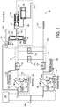
- Fig. 1 a partial view of an embodiment of a system in accordance with the disclosure is shown in Fig. 1 and is designated generally by reference character 100.
- FIGs. 2-3 Other embodiments of systems in accordance with the disclosure, or aspects thereof, are provided in Figs. 2-3 as will be described.
- the systems and methods described herein can be used to provide backup capabilities for pump redundancy, e.g. enabling the benefits of variable displacement pumps (VDPs) in applications where traditionally VDPs could not be used.
- VDPs variable displacement pumps
- the system 100 includes a first pump 102 connected to an inlet line 104 and connected to a first outlet line 106 for supplying a first sub-system 112, e.g. a gas generator of a gas turbine in engine as indicated by GG in Fig. 1 , over a first pressure schedule.
- a second pump 108 is connected to the inlet line 104 and is connected to a second outlet line 110 for supplying a second subsystem 114, e.g. a hydraulic actuation system of hydraulic actuated devices, over a second pressure schedule.
- the first pressure schedule can have its a highest pressure be lower than the highest pressure of the second schedule. It is also contemplated that the second pressure schedule can be fully above the pressure range of the first pressure schedule.
- a backup selector 116 is in fluid communication with the first and second outlet lines 106, 110.
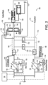
- the backup selector 116 is configured to switch to a first backup mode, shown in Fig. 2 , to supply the first sub-system 112 from the second pump 108 upon failure of the first pump 102.
- the backup selector 116 is configured to switch to a second backup mode to supply the second sup-system 114 from the first pump 102 upon failure of the second pump 108, as shown in Fig. 3 .
- the backup selector includes a selector valve (SV) 118 connected in fluid communication between the first outlet line 106 and the second outlet line 110.
- the SV 118 can be any suitable type of selector valve such as a solenoid valve.
- the SV 118 is configured to block fluid communication between the first and second outlet lines 106, 110 in a normal mode as shown in Fig. 1 , to allow fluid communication between the first and second outlet lines 106, 110 in the first backup mode shown in Fig. 2 , and to block fluid communication between the first and second outlet lines 106, 110 in the second backup mode shown in Fig. 3 .
- the backup selector 116 includes a check valve (CV) 120 connected in fluid communication between the first outlet 106 line and the second outlet line 110.
- CV check valve
- the CV 120 is configured to block fluid communication between the first and second outlet lines 106, 110 in the normal mode as shown in Fig. 1 , to block fluid communication between the first and second outlet lines 106, 110 in the first backup mode shown in Fig. 2 , and to allow fluid communication from the first outlet line into the second outlet line 106, 110 in the second backup mode shown in Fig. 3 .
- the CV 120 connects upstream of where the SV 118 connects in both the first outlet line 106 and in the second outlet line 110, relative to flow in the normal mode of Fig. 1 .
- the CV 120 can actuate passively to allow flow therethrough only when the pressure in the first outlet line 106 is higher than the pressure in the second outlet line 110, e.g. in the second backup mode shown in Fig. 3 .
- the backup selector 116 includes a check valve 122 in the first outlet line 106 between the first pump 102 and where the CV 120 an SV 118 connect to the first outlet line 106.
- the check valve 122 is configured to black backflow into the first pump 102 in the first backup mode of Fig. 2 , e.g. where the first pump 102 is degraded or failed.
- the backup selector 116 includes a check valve 124 in the second outlet line 110 between the second pump 108 and where the CV 120 and SV 118 connect to the second outlet line 110.
- the check valve 124 is configured to block backflow into the second pump 108 in the second backup mode shown in Fig. 3 , e.g. where the second pump 108 is degraded or failed.
- the first pump 102 is a variable displacement pump (VDP).
- An electrohydraulic servo valve (EHSV) 126 is operatively connected to a controller 128 for control of the first pump 102.
- the EHSV 126 includes a first connection 130 to the inlet line 104, a second connection 132 to the first outlet line 106, and a pump control line 134 operatively connected to actuate a variable displacement mechanism of the first pump 102.
- the second pump 108 is a variable displacement pump (VDP).
- An EHSV 136 is operatively connected to the controller 128 for control of the second pump 108.
- the EHSV 136 includes a first connection 138 to the inlet line 104, a second connection 140 to the second outlet line 110, and a pump control line 142 operatively connected to actuate a variable displacement mechanism of the second pump 108.
- a first pressure sensor 144 is included in the first outlet line 106, and the first pump 102 includes a sensor 146, e.g. a linear variable displacement transformer (LVDT) connected to the variable displacement mechanism of the first pump 102.
- LVDT linear variable displacement transformer
- Each of the sensors 144, 146 are connected to the controller 128 for feedback control of the first pump.
- a second pressure sensor 148 is included in the second outlet line 110, and the second pump 108 includes a sensor 150, e.g.
- LVDT linear variable displacement transformer
- Each of the sensors 144, 146 are connected to the controller 128 for feedback control of the first pump.
- the connections of the sensors 144, 146, 148, 150 to the controller 128 are deliberately omitted in Figs. 1-3 to avoid obscuring the fluid lines.
- a metering valve (MV) 152 is connected to the first outlet line 106 to step down pressure from the second output line down to a third pressure P3 below a second pressure P2 of the first outlet line 106. This allows operation of the two different pressure schedules of the subsystems 112, 114 in the event of one-pump operation as in the backup modes of Figs. 2-3 .
- the MV 152 includes a piston 154 configured to meter flow from the first outlet line 106 to a line 156 at the third pressure P3 based on position of the piston 154 in a valve sleeve of the MV 152.
- An EHSV 158 is operatively connected to the controller 128, to the inlet line 104, and to the first outlet line 106.
- the EHSV 158 includes a first control line 160 connected to a first end of the piston 152, and a second control line 162 connected to a second end of the piston 154.
- the EHSV 158 is configured to pressurize the first and second control lines 160, 162 to control position of the piston 154 based on commands from the controller 128.
- the MV 152 includes a position sensor 164, e.g. an LVDT, operatively connected to generate feedback indicative of position of the piston 154 in the sleeve for the controller 128.
- the controller 128 is operatively connected to the position sensor 164 to control the MV 152 based on the feedback indicative of position of the piston 154 in its sleeve.
- a pressure regulating valve (PRV) 166 is connected to the line 156 at the third pressure P3 from the MV 152 to receive flow from the MV 152, and an outlet configured to output regulated pressure flow to a regulated pressure flow line 168 based on position of a regulating piston 170 in a regulating piston sleeve of the PRV 166.
- a first end of the regulating piston 170 is connected to the line 156 from the MV 152.
- the second end of the regulating piston 170 is connected to the first outlet line 106 so the position of the regulating piston 170 in its sleeve is based on pressure differential between the second and third pressures P2 and P3.
- a shutoff valve (SOV) 172 is connected in the line 168 from the outlet of the PRV 166, wherein the SOV 172 is configured to block flow from the PRV 166 below a predetermined threshold for shutoff, to prevent flow to/from the subsystem 112, e.g. while the system 100 is shut off.
- SOV shutoff valve
- the controller 128 is operatively connected to control each of the first and second pumps in the normal mode of Fig. 1 and in the backup modes of Figs. 2-3 based on feedback from the first sensor 144 operatively connected to communicate feedback indicative of pressure in the first outlet line 106 to the controller, and from the second sensor 148 operatively connected to communicate feedback indicative of pressure in the second outlet line 110 to the controller 128.
- the controller 128 is also operatively connected for active control of the SV 118 for switching among the modes described herein.
- the first and second pumps 102, 108 can each be oversized, e.g., to have at least 40% greater capacity than needed for full power of their respective sub-systems during normal operation as shown in Fig. 1 . This over-sizing for the normal mode helps ensure when only one pump is running in the backup modes of Figs. 2-3 , both sub-systems 112, 114 have adequate pressure for continued operation.
- Systems and methods as disclosed herein offer various potential benefits. They can improves fuel system reliability, can provides pump back-up capability, and can offer cost savings since both pumps can be identical to one another.
- VDPs variable displacement pumps
Landscapes
- Engineering & Computer Science (AREA)
- Mechanical Engineering (AREA)
- General Engineering & Computer Science (AREA)
- Chemical & Material Sciences (AREA)
- Combustion & Propulsion (AREA)
- Control Of Positive-Displacement Pumps (AREA)
Abstract
A system includes a first pump (102) connected to an inlet line (104) and connected to a first outlet line (106) for supplying a first sub-system (112) over a first pressure schedule. A second pump (108) is connected to the inlet line and connected to a second outlet line (110) for supplying a second subsystem (114) over a second pressure schedule. A backup selector (116) is in fluid communication with the first and second outlet lines. The backup selector is configured to switch to a first backup mode to supply the first sub-system from the second pump upon failure of the first pump. The backup selector is configured to switch to a second backup mode to supply the second sup-system from the first pump upon failure of the second pump.
Description
- The present disclosure relates to pump operation, and more particularly to backup functions for pumps such as in aerospace applications.
- In order to minimize horsepower required for fuel pumping, variable displacement pumps (VDPs) are desirable. However, VDPs have higher part count than other pump types such as centrifugal pumps, so while VDPs can be made very reliable, they are not considered to be the most reliable type of pump. The reliability tradeoff of VDPs has hereto for driven some preclusions of their use in some applications, such as for single engine aircraft.
- The conventional techniques have been considered satisfactory for their intended purpose. However, there is an ever present need for improved systems and methods for obtaining the horsepower benefits of VDPs without necessarily trading off reliability. This disclosure provides a solution for this need.
- A system includes a first pump connected to an inlet line and connected to a first outlet line for supplying a first sub-system over a first pressure schedule. A second pump is connected to the inlet line and connected to a second outlet line for supplying a second subsystem over a second pressure schedule. A backup selector is in fluid communication with the first and second outlet lines. The backup selector is configured to switch to a first backup mode to supply the first sub-system from the second pump upon failure of the first pump. The backup selector is configured to switch to a second backup mode to supply the second sup-system from the first pump upon failure of the second pump.
- The backup selector can include a selector valve (SV) connected in fluid communication between the first outlet line and the second outlet line, wherein the SV is configured to block fluid communication between the first and second outlet lines in a normal mode, to allow fluid communication between the first and second outlet lines in the first backup mode, and to block fluid communication between the first and second outlet lines in the second backup mode. The backup selector can include a check valve (CV) connected in fluid communication between the first outlet line and the second outlet line, wherein the CV is configured to block fluid communication between the first and second outlet lines in the normal mode, to block fluid communication between the first and second outlet lines in the first backup mode, and to allow fluid communication from the first outlet line into the second outlet line in the second backup mode. The CV can connect upstream of where the SV connects in both the first outlet line and in the second outlet line, relative to flow in the normal mode.
- The backup selector can include a check valve in the first outlet line between the first pump and where the CV an SV connect to the first outlet line, configured to black backflow into the first pump in the first backup mode. The backup selector can include a check valve in the second outlet line between the second pump and where the CV and SV connect to the second outlet line, configured to block backflow into the second pump in the second backup mode.
- The first pump can be a variable displacement pump (VDP). An electrohydraulic servo valve (EHSV) can be operatively connected to a controller for control of the first pump. The EHSV can include a first connection to the inlet line, a second connection to the first outlet line, and a pump control line operatively connected to actuate a variable displacement mechanism of the VDP.
- The second pump can be a variable displacement pump (VDP). An electrohydraulic servo valve (EHSV) can be operatively connected to a controller for control of the second pump. The EHSV can include a first connection to the inlet line, a second connection to the second outlet line, and a pump control line operatively connected to actuate a variable displacement mechanism of the VDP.
- The first pressure schedule can have a high pressure that is lower than a high pressure of the second schedule. The first pump can be configured to supply a gas generator as the first sub-system, wherein the second pump is configured to supply an actuation system as the second sub-system.
- A metering valve (MV) can be connected to the first outlet line to step down pressure from the second output line down to a third pressure below a second pressure of the first outlet line. The MV can include a piston configured to meter flow from the first outlet line to a line at the third pressure based on position of the piston in a valve sleeve.
- An electrohydraulic control valve (EHSV) can be operatively connected to a controller, to the inlet line, and to the first outlet line. The EHSV can include a first control line connected to a first end of the piston, and a second control line connected to a second end of the piston. The EHSV can be configured to pressurize the first and second control lines to control position of the piston based on commands from the controller. The MV can include a position sensor operatively connected to generate feedback indicative of position of the piston in the sleeve. The controller can be operatively connected to the position sensor to control the MV based on the feedback indicative of position of the piston in the sleeve.
- A pressure regulating valve (PRV) can be connected to a line at the third pressure from the MV to receive flow from the MV, and an outlet configured to output regulated pressure flow to a regulated pressure flow line based on position of a regulating piston in a regulating piston sleeve. A first end of the regulating piston can be connected to the line at the third pressure from the MV, and wherein a second end of the regulating piston is connected to the first outlet line so position of the regulating piston in the regulating sleeve is based on pressure differential between the second and third pressures.
- A shutoff valve (SOV) can be connected in a line from the outlet of the PRV, wherein the SOV is configured to block flow from the PRV below a predetermined threshold for shutoff. A controller can be operatively connected to control each of the first and second pumps based on feedback from a first sensor operatively connected to communicate feedback indicative of pressure in the first outlet line to the controller and from a second sensor operatively connected to communicate feedback indicative of pressure in the second outlet line to the controller. The first pump can be sized to have at least 40% greater capacity than needed for full power of the first sub-system, and the second pump can be sized to have at least 40% greater capacity than needed for full power of the second sub-system.
- These and other features of the systems and methods of the subject disclosure will become more readily apparent to those skilled in the art from the following detailed description of the preferred embodiments taken in conjunction with the drawings.
- So that those skilled in the art to which the subject disclosure appertains will readily understand how to make and use the devices and methods of the subject disclosure without undue experimentation, preferred embodiments thereof will be described in detail herein below with reference to certain figures, wherein:
-
Fig. 1 is a schematic view of an embodiment of a system constructed in accordance with the present disclosure, showing the pumps operating in normal mode; -
Fig. 2 is a schematic view of the system ofFig. 1 , showing the first backup mode; and -
Fig. 3 is a schematic view of the system ofFig. 1 , showing the second backup mode. - Reference will now be made to the drawings wherein like reference numerals identify similar structural features or aspects of the subject disclosure. For purposes of explanation and illustration, and not limitation, a partial view of an embodiment of a system in accordance with the disclosure is shown in
Fig. 1 and is designated generally byreference character 100. Other embodiments of systems in accordance with the disclosure, or aspects thereof, are provided inFigs. 2-3 as will be described. The systems and methods described herein can be used to provide backup capabilities for pump redundancy, e.g. enabling the benefits of variable displacement pumps (VDPs) in applications where traditionally VDPs could not be used. - The
system 100 includes afirst pump 102 connected to aninlet line 104 and connected to afirst outlet line 106 for supplying afirst sub-system 112, e.g. a gas generator of a gas turbine in engine as indicated by GG inFig. 1 , over a first pressure schedule. Asecond pump 108 is connected to theinlet line 104 and is connected to asecond outlet line 110 for supplying asecond subsystem 114, e.g. a hydraulic actuation system of hydraulic actuated devices, over a second pressure schedule. The first pressure schedule can have its a highest pressure be lower than the highest pressure of the second schedule. It is also contemplated that the second pressure schedule can be fully above the pressure range of the first pressure schedule. - A
backup selector 116 is in fluid communication with the first andsecond outlet lines backup selector 116 is configured to switch to a first backup mode, shown inFig. 2 , to supply thefirst sub-system 112 from thesecond pump 108 upon failure of thefirst pump 102. Thebackup selector 116 is configured to switch to a second backup mode to supply the second sup-system 114 from thefirst pump 102 upon failure of thesecond pump 108, as shown inFig. 3 . - The backup selector includes a selector valve (SV) 118 connected in fluid communication between the
first outlet line 106 and thesecond outlet line 110. TheSV 118 can be any suitable type of selector valve such as a solenoid valve. TheSV 118 is configured to block fluid communication between the first andsecond outlet lines Fig. 1 , to allow fluid communication between the first andsecond outlet lines Fig. 2 , and to block fluid communication between the first andsecond outlet lines Fig. 3 . Thebackup selector 116 includes a check valve (CV) 120 connected in fluid communication between thefirst outlet 106 line and thesecond outlet line 110. TheCV 120 is configured to block fluid communication between the first andsecond outlet lines Fig. 1 , to block fluid communication between the first andsecond outlet lines Fig. 2 , and to allow fluid communication from the first outlet line into thesecond outlet line Fig. 3 . TheCV 120 connects upstream of where theSV 118 connects in both thefirst outlet line 106 and in thesecond outlet line 110, relative to flow in the normal mode ofFig. 1 . TheCV 120 can actuate passively to allow flow therethrough only when the pressure in thefirst outlet line 106 is higher than the pressure in thesecond outlet line 110, e.g. in the second backup mode shown inFig. 3 . - The
backup selector 116 includes acheck valve 122 in thefirst outlet line 106 between thefirst pump 102 and where theCV 120 anSV 118 connect to thefirst outlet line 106. Thecheck valve 122 is configured to black backflow into thefirst pump 102 in the first backup mode ofFig. 2 , e.g. where thefirst pump 102 is degraded or failed. Thebackup selector 116 includes acheck valve 124 in thesecond outlet line 110 between thesecond pump 108 and where theCV 120 andSV 118 connect to thesecond outlet line 110. Thecheck valve 124 is configured to block backflow into thesecond pump 108 in the second backup mode shown inFig. 3 , e.g. where thesecond pump 108 is degraded or failed. - The
first pump 102 is a variable displacement pump (VDP). An electrohydraulic servo valve (EHSV) 126 is operatively connected to acontroller 128 for control of thefirst pump 102. TheEHSV 126 includes afirst connection 130 to theinlet line 104, asecond connection 132 to thefirst outlet line 106, and apump control line 134 operatively connected to actuate a variable displacement mechanism of thefirst pump 102. Thesecond pump 108 is a variable displacement pump (VDP). AnEHSV 136 is operatively connected to thecontroller 128 for control of thesecond pump 108. TheEHSV 136 includes afirst connection 138 to theinlet line 104, asecond connection 140 to thesecond outlet line 110, and apump control line 142 operatively connected to actuate a variable displacement mechanism of thesecond pump 108. Afirst pressure sensor 144 is included in thefirst outlet line 106, and thefirst pump 102 includes asensor 146, e.g. a linear variable displacement transformer (LVDT) connected to the variable displacement mechanism of thefirst pump 102. Each of thesensors controller 128 for feedback control of the first pump. Similarly, asecond pressure sensor 148 is included in thesecond outlet line 110, and thesecond pump 108 includes asensor 150, e.g. a linear variable displacement transformer (LVDT) 146 connected to the variable displacement mechanism of thesecond pump 108. Each of thesensors controller 128 for feedback control of the first pump. The connections of thesensors controller 128 are deliberately omitted inFigs. 1-3 to avoid obscuring the fluid lines. - A metering valve (MV) 152 is connected to the
first outlet line 106 to step down pressure from the second output line down to a third pressure P3 below a second pressure P2 of thefirst outlet line 106. This allows operation of the two different pressure schedules of thesubsystems Figs. 2-3 . TheMV 152 includes apiston 154 configured to meter flow from thefirst outlet line 106 to aline 156 at the third pressure P3 based on position of thepiston 154 in a valve sleeve of theMV 152. - An
EHSV 158 is operatively connected to thecontroller 128, to theinlet line 104, and to thefirst outlet line 106. TheEHSV 158 includes afirst control line 160 connected to a first end of thepiston 152, and asecond control line 162 connected to a second end of thepiston 154. TheEHSV 158 is configured to pressurize the first andsecond control lines piston 154 based on commands from thecontroller 128. TheMV 152 includes aposition sensor 164, e.g. an LVDT, operatively connected to generate feedback indicative of position of thepiston 154 in the sleeve for thecontroller 128. Thecontroller 128 is operatively connected to theposition sensor 164 to control theMV 152 based on the feedback indicative of position of thepiston 154 in its sleeve. - A pressure regulating valve (PRV) 166 is connected to the
line 156 at the third pressure P3 from theMV 152 to receive flow from theMV 152, and an outlet configured to output regulated pressure flow to a regulatedpressure flow line 168 based on position of aregulating piston 170 in a regulating piston sleeve of thePRV 166. A first end of theregulating piston 170 is connected to theline 156 from theMV 152. The second end of theregulating piston 170 is connected to thefirst outlet line 106 so the position of theregulating piston 170 in its sleeve is based on pressure differential between the second and third pressures P2 and P3. A shutoff valve (SOV) 172 is connected in theline 168 from the outlet of thePRV 166, wherein theSOV 172 is configured to block flow from thePRV 166 below a predetermined threshold for shutoff, to prevent flow to/from thesubsystem 112, e.g. while thesystem 100 is shut off. - The
controller 128 is operatively connected to control each of the first and second pumps in the normal mode ofFig. 1 and in the backup modes ofFigs. 2-3 based on feedback from thefirst sensor 144 operatively connected to communicate feedback indicative of pressure in thefirst outlet line 106 to the controller, and from thesecond sensor 148 operatively connected to communicate feedback indicative of pressure in thesecond outlet line 110 to thecontroller 128. Thecontroller 128 is also operatively connected for active control of theSV 118 for switching among the modes described herein. - The first and
second pumps Fig. 1 . This over-sizing for the normal mode helps ensure when only one pump is running in the backup modes ofFigs. 2-3 , bothsub-systems - Systems and methods as disclosed herein offer various potential benefits. They can improves fuel system reliability, can provides pump back-up capability, and can offer cost savings since both pumps can be identical to one another.
- The methods and systems of the present disclosure, as described above and shown in the drawings, provide for backup capabilities for pump redundancy, e.g. enabling the benefits of variable displacement pumps (VDPs) in applications where traditionally VDPs could not be used. While the apparatus and methods of the subject disclosure have been shown and described with reference to preferred embodiments, those skilled in the art will readily appreciate that changes and/or modifications may be made thereto without departing from the scope of the invention as defined by the claims.
Claims (15)
- A system comprising:a first pump (102) connected to an inlet line (104) and connected to a first outlet line (106) for supplying a first sub-system (112) over a first pressure schedule;a second pump (108) connected to the inlet line and (104) connected to a second outlet line (110) for supplying a second subsystem (114) over a second pressure schedule; anda backup selector (116) in fluid communication with the first and second outlet lines,wherein the backup selector is configured to switch to a first backup mode to supply the first sub-system from the second pump upon failure of the first pump, andwherein the backup selector is configured to switch to a second backup mode to supply the second sub-system from the first pump upon failure of the second pump.
- The system as recited in claim 1, wherein the backup selector includes a selector valve, SV, (118) connected in fluid communication between the first outlet line and the second outlet line, wherein the SV is configuredto block fluid communication between the first and second outlet lines in a normal mode,to allow fluid communication between the first and second outlet lines in the first backup mode, andto block fluid communication between the first and second outlet lines in the second backup mode.
- The system as recited in claim 2, wherein the backup selector includes a check valve, CV, (120) connected in fluid communication between the first outlet line and the second outlet line, wherein the CV is configuredto block fluid communication between the first and second outlet lines in the normal mode,to block fluid communication between the first and second outlet lines in the first backup mode, andto allow fluid communication from the first outlet line into the second outlet line in the second backup mode.
- The system as recited in claim 3, wherein the CV connects upstream of where the SV connects in both the first outlet line and in the second outlet line, relative to flow in the normal mode.
- The system as recited in claim 4, wherein the backup selector includes:a check valve in the first outlet line between the first pump and where the CV an SV connect to the first outlet line, configured to black backflow into the first pump in the first backup mode; anda check valve in the second outlet line between the second pump and where the CV and SV connect to the second outlet line, configured to block backflow into the second pump in the second backup mode.
- The system as recited in any preceding claim, wherein the first pump is a variable displacement pump, VDP.
- The system as recited in claim 6, further comprising an electrohydraulic servo valve, EHSV, (126) operatively connected to a controller for control of the first pump, wherein the EHSV includes a first connection to the inlet line, a second connection to the first outlet line, and a pump control line operatively connected to actuate a variable displacement mechanism of the VDP.
- The system as recited in any preceding claim, wherein the second pump is a variable displacement pump, VDP,, and optionally further comprising an electrohydraulic servo valve, EHSV, operatively connected to a controller (128) for control of the second pump, wherein the EHSV includes a first connection to the inlet line, a second connection to the second outlet line, and a pump control line operatively connected to actuate a variable displacement mechanism of the VDP.
- The system as recited in any preceding claim, wherein the first pressure schedule has a high pressure that is lower than a high pressure of the second schedule, and optionally wherein the first pump is configured to supply a gas generator as the first sub-system, wherein the second pump is configured to supply an actuation system as the second sub-system.
- The system as recited in any preceding claim, further comprising a metering valve, MV, (152) connected to the first outlet line to step down pressure from the second output line down to a third pressure below a second pressure of the first outlet line., and optionally wherein the MV includes a piston (154) configured to meter flow from the first outlet line to a line at the third pressure based on position of the piston in a valve sleeve.
- The system as recited in claim 10, further comprising:
an electrohydraulic control valve, EHSV, (126) operatively connected to a controller, to the inlet line, and to the first outlet line, wherein the EHSV includes a first control line connected to a first end of the piston, and a second control line connected to a second end of the piston, wherein the EHSV is configured to pressurize the first and second control lines to control position of the piston based on commands from the controller., and optionally wherein the MV includes a position sensor (164) operatively connected to generate feedback indicative of position of the piston in the sleeve, wherein the controller is operatively connected to the position sensor to control the MV based on the feedback indicative of position of the piston in the sleeve. - The system as recited in claim 11, further comprising a pressure regulating valve, PRV, (166) connected to a line at the third pressure from the MV to receive flow from the MV, and an outlet configured to output regulated pressure flow to a regulated pressure flow line based on position of a regulating piston (170) in a regulating piston sleeve.
- The system as recited in claim 12, wherein a first end of the regulating piston is connected to the line at the third pressure from the MV, and wherein a second end of the regulating piston is connected to the first outlet line so position of the regulating piston in the regulating sleeve is based on pressure differential between the second and third pressures., and optionally further comprising a shutoff valve, SOV, (172) connected in a line from the outlet of the PRV, wherein the SOV is configured to block flow from the PRV below a predetermined threshold for shutoff.
- The system as recited in any preceding claim, further comprising a controller operatively connected to control each of the first and second pumps based on feedback from a first sensor operatively connected to communicate feedback indicative of pressure in the first outlet line to the controller and from a second sensor operatively connected to communicate feedback indicative of pressure in the second outlet line to the controller.
- The system as recited in any preceding claim, wherein the first pump is sized to have at least 40% greater capacity than needed for full power of the first sub-system, and wherein the second pump is sized to have at least 40% greater capacity than needed for full power of the second sub-system.
Applications Claiming Priority (1)
| Application Number | Priority Date | Filing Date | Title |
|---|---|---|---|
| US18/084,768 US11976599B1 (en) | 2022-12-20 | 2022-12-20 | Pumps with backup capability |
Publications (1)
| Publication Number | Publication Date |
|---|---|
| EP4390127A1 true EP4390127A1 (en) | 2024-06-26 |
Family
ID=89224745
Family Applications (1)
| Application Number | Title | Priority Date | Filing Date |
|---|---|---|---|
| EP23218748.4A Pending EP4390127A1 (en) | 2022-12-20 | 2023-12-20 | Pumps with backup capability |
Country Status (2)
| Country | Link |
|---|---|
| US (1) | US11976599B1 (en) |
| EP (1) | EP4390127A1 (en) |
Cited By (1)
| Publication number | Priority date | Publication date | Assignee | Title |
|---|---|---|---|---|
| EP4520944A1 (en) * | 2023-09-11 | 2025-03-12 | Hamilton Sundstrand Corporation | Variable displacement pump (vdp) systems with dry-out centrifugal main pump |
Families Citing this family (1)
| Publication number | Priority date | Publication date | Assignee | Title |
|---|---|---|---|---|
| US12524027B2 (en) * | 2024-04-22 | 2026-01-13 | Hamilton Sundstrand Corporation | Fuel system with boosted and cooled variable displacement main fuel pump and electromechanical actuators |
Citations (3)
| Publication number | Priority date | Publication date | Assignee | Title |
|---|---|---|---|---|
| US20100037867A1 (en) * | 2008-08-12 | 2010-02-18 | Woodward Governor Company | System for Metering a Fuel Supply |
| US20150101339A1 (en) * | 2013-10-16 | 2015-04-16 | Hamilton Sundstrand Corporation | Energy efficient pump system |
| US20210222625A1 (en) * | 2020-01-20 | 2021-07-22 | Hamilton Sundstrand Corporation | Dual pump unit with boost pump |
Family Cites Families (31)
| Publication number | Priority date | Publication date | Assignee | Title |
|---|---|---|---|---|
| US2506611A (en) * | 1948-03-02 | 1950-05-09 | Westinghouse Electric Corp | Fuel control for aviation gas turbine power plants |
| US5116362A (en) * | 1990-12-03 | 1992-05-26 | United Technologies Corporation | Fuel metering and actuation system |
| US5806300A (en) * | 1995-12-22 | 1998-09-15 | United Technologies Corporation | Electronic control for a variable delivery, positive displacement fuel pump |
| US6102001A (en) | 1998-12-04 | 2000-08-15 | Woodward Governor Company | Variable displacement pump fuel metering system and electrohydraulic servo-valve for controlling the same |
| US6487847B1 (en) | 2000-11-03 | 2002-12-03 | General Electric Company | Gas turbine engine fuel control system |
| US20050100447A1 (en) | 2003-11-11 | 2005-05-12 | Desai Mihir C. | Flow control system for a gas turbine engine |
| GB0401207D0 (en) * | 2004-01-21 | 2004-02-25 | Goodrich Control Sys Ltd | Fuel supply system |
| US8128378B2 (en) | 2007-07-30 | 2012-03-06 | Honeywell International Inc. | Dual mode compensation for variable displacement pump fluid metering system |
| DE102007052276B3 (en) | 2007-10-31 | 2009-01-15 | Nordex Energy Gmbh | Device for ventilating a rotor hub of a wind energy plant |
| US8166765B2 (en) * | 2008-10-15 | 2012-05-01 | Woodward, Inc. | Fuel delivery and control system including a variable displacement actuation pump supplementing a fixed displacement main pump |
| US8302406B2 (en) * | 2008-10-15 | 2012-11-06 | Woodward, Inc. | Fuel delivery and control system including a positive displacement actuation pump with a variable pressure regulator supplementing a fixed displacement main fuel pump |
| US8172551B2 (en) | 2009-03-25 | 2012-05-08 | Woodward, Inc. | Variable actuation pressure system for independent pressure control |
| US8192172B2 (en) | 2009-04-06 | 2012-06-05 | Woodward, Inc. | Flow sensing shutoff valve |
| FR2950863B1 (en) * | 2009-10-06 | 2012-03-02 | Snecma | FUEL SUPPLY CIRCUIT FOR AN AIRCRAFT ENGINE |
| FR2950864B1 (en) * | 2009-10-06 | 2011-11-25 | Snecma | FUEL SUPPLY CIRCUIT FOR AN AIRCRAFT ENGINE |
| FR2953563B1 (en) * | 2009-12-07 | 2012-02-03 | Snecma | FUEL SUPPLY INSTALLATION OF AN AIRCRAFT TURBOJET ENGINE |
| US8991152B2 (en) * | 2011-01-24 | 2015-03-31 | Hamilton Sundstrand Corporation | Aircraft engine fuel system |
| US8869509B2 (en) | 2011-06-09 | 2014-10-28 | Woodward, Inc. | Accessory flow recovery system and method for thermal efficient pump and control system |
| JP6131785B2 (en) * | 2013-08-30 | 2017-05-24 | 株式会社Ihi | Aircraft engine fuel supply system |
| WO2015045905A1 (en) * | 2013-09-25 | 2015-04-02 | 株式会社Ihi | Fuel system |
| GB201400085D0 (en) | 2014-01-03 | 2014-02-19 | Rolls Royce Controls & Data Services Ltd | Engine fuel control system |
| US9574500B2 (en) | 2014-02-28 | 2017-02-21 | General Electric Company | Direct metering using a variable displacement vane pump |
| US9850917B2 (en) | 2014-09-23 | 2017-12-26 | Woodward, Inc. | Pump authority switching apparatus for a fluid distribution system |
| US10502138B2 (en) * | 2016-04-11 | 2019-12-10 | Hamilton Sundstrand Corporation | Dual pump fuel system with pump sharing connection |
| EP3236050A1 (en) | 2016-04-20 | 2017-10-25 | Rolls-Royce PLC | Engine fuel control system |
| US20180340501A1 (en) | 2017-05-23 | 2018-11-29 | Weishun Willaim Ni | Variable displacement fuel pump with position sensor |
| US20190112987A1 (en) * | 2017-10-17 | 2019-04-18 | Hamilton Sundstrand Corporation | Electric cruise pump system |
| US10900421B2 (en) * | 2018-10-17 | 2021-01-26 | Woodward, Inc. | Direct feedback regarding metered flow of fuel system |
| US20210079848A1 (en) * | 2019-03-20 | 2021-03-18 | United Technologies Corporation | Secondary fuel flow demand fuel pumping system |
| US11674455B2 (en) | 2021-03-26 | 2023-06-13 | Hamilton Sundstrand Corporation | Variable displacement pump with active bypass feedback control |
| US11629643B1 (en) * | 2022-01-07 | 2023-04-18 | Hamilton Sundstrand Corporation | Fuel pump systems |
-
2022
- 2022-12-20 US US18/084,768 patent/US11976599B1/en active Active
-
2023
- 2023-12-20 EP EP23218748.4A patent/EP4390127A1/en active Pending
Patent Citations (3)
| Publication number | Priority date | Publication date | Assignee | Title |
|---|---|---|---|---|
| US20100037867A1 (en) * | 2008-08-12 | 2010-02-18 | Woodward Governor Company | System for Metering a Fuel Supply |
| US20150101339A1 (en) * | 2013-10-16 | 2015-04-16 | Hamilton Sundstrand Corporation | Energy efficient pump system |
| US20210222625A1 (en) * | 2020-01-20 | 2021-07-22 | Hamilton Sundstrand Corporation | Dual pump unit with boost pump |
Cited By (2)
| Publication number | Priority date | Publication date | Assignee | Title |
|---|---|---|---|---|
| EP4520944A1 (en) * | 2023-09-11 | 2025-03-12 | Hamilton Sundstrand Corporation | Variable displacement pump (vdp) systems with dry-out centrifugal main pump |
| US12366207B2 (en) | 2023-09-11 | 2025-07-22 | Hamilton Sundstrand Corporation | Variable displacement pump (VDP) systems with dry-out centrifugal main pump |
Also Published As
| Publication number | Publication date |
|---|---|
| US11976599B1 (en) | 2024-05-07 |
Similar Documents
| Publication | Publication Date | Title |
|---|---|---|
| EP4390127A1 (en) | Pumps with backup capability | |
| EP2762711B1 (en) | Engine fuel control system | |
| EP2837799B1 (en) | Engine fuel control system | |
| US8881529B2 (en) | Modular fuel supply device for a gas turbine including a fuel supply device having an integrated control device | |
| US11788476B1 (en) | Fluid system with variable pump discharge pressure and method | |
| EP4627205A1 (en) | System and method for in situ verification of redundant electro-hydraulic servo valve (ehsv) operational status in redundant flow control systems | |
| EP4400702A1 (en) | High turn down ratio direct control for variable displacement pumps | |
| US12000346B2 (en) | Redundant electro-hydraulic servo valve (EHSV) control in a fuel metering system | |
| EP4382747B1 (en) | Variable displacement pump with flow delivery to different systems with different pressure schedules | |
| EP4520941A1 (en) | Variable displacement pump (vdp) systems with dual dry out pumps | |
| EP3120004B1 (en) | Actuation assembly and method of operating an actuator | |
| EP4283111A1 (en) | Dual valve fuel metering systems | |
| EP4390099A1 (en) | Variable displacement pump with back-up | |
| EP4477881A1 (en) | Direct controlled variable displacement pump fuel systems with low pressure thermal recirculation pumping | |
| EP4400720A1 (en) | High turn down ratio direct control for variable displacement pumps with flow sensing | |
| EP4467795A1 (en) | Active displacement control against temperature target for a variable displacement pump | |
| EP4495405A1 (en) | Dedicated thermal recirculation control for an aircraft engine fuel system | |
| EP4467793A1 (en) | Direct controlled variable displacement valves with dual set point pressure relief | |
| EP4495425A1 (en) | Combined high pressure relief and bypass valves | |
| EP4450810A1 (en) | Electrically direct controlled variable displacement pumps | |
| EP4400719A1 (en) | Direct control for variable displacement pumps | |
| US12366207B2 (en) | Variable displacement pump (VDP) systems with dry-out centrifugal main pump | |
| WO2024006185A1 (en) | Redundant electro-hydraulic servo valve (ehsv) control in a fuel metering system | |
| CN120426177A (en) | A wind power hydraulic pitch control power module |
Legal Events
| Date | Code | Title | Description |
|---|---|---|---|
| PUAI | Public reference made under article 153(3) epc to a published international application that has entered the european phase |
Free format text: ORIGINAL CODE: 0009012 |
|
| STAA | Information on the status of an ep patent application or granted ep patent |
Free format text: STATUS: THE APPLICATION HAS BEEN PUBLISHED |
|
| AK | Designated contracting states |
Kind code of ref document: A1 Designated state(s): AL AT BE BG CH CY CZ DE DK EE ES FI FR GB GR HR HU IE IS IT LI LT LU LV MC ME MK MT NL NO PL PT RO RS SE SI SK SM TR |
|
| STAA | Information on the status of an ep patent application or granted ep patent |
Free format text: STATUS: REQUEST FOR EXAMINATION WAS MADE |
|
| 17P | Request for examination filed |
Effective date: 20241223 |