EP4390083A1 - Forced induction device for an internal combustion engine - Google Patents
Forced induction device for an internal combustion engine Download PDFInfo
- Publication number
- EP4390083A1 EP4390083A1 EP23217109.0A EP23217109A EP4390083A1 EP 4390083 A1 EP4390083 A1 EP 4390083A1 EP 23217109 A EP23217109 A EP 23217109A EP 4390083 A1 EP4390083 A1 EP 4390083A1
- Authority
- EP
- European Patent Office
- Prior art keywords
- compressor
- turbine
- induction device
- forced induction
- internal combustion
- Prior art date
- Legal status (The legal status is an assumption and is not a legal conclusion. Google has not performed a legal analysis and makes no representation as to the accuracy of the status listed.)
- Granted
Links
Images
Classifications
-
- F—MECHANICAL ENGINEERING; LIGHTING; HEATING; WEAPONS; BLASTING
- F02—COMBUSTION ENGINES; HOT-GAS OR COMBUSTION-PRODUCT ENGINE PLANTS
- F02B—INTERNAL-COMBUSTION PISTON ENGINES; COMBUSTION ENGINES IN GENERAL
- F02B39/00—Component parts, details, or accessories relating to, driven charging or scavenging pumps, not provided for in groups F02B33/00 - F02B37/00
- F02B39/02—Drives of pumps; Varying pump drive gear ratio
- F02B39/08—Non-mechanical drives, e.g. fluid drives having variable gear ratio
-
- F—MECHANICAL ENGINEERING; LIGHTING; HEATING; WEAPONS; BLASTING
- F02—COMBUSTION ENGINES; HOT-GAS OR COMBUSTION-PRODUCT ENGINE PLANTS
- F02B—INTERNAL-COMBUSTION PISTON ENGINES; COMBUSTION ENGINES IN GENERAL
- F02B39/00—Component parts, details, or accessories relating to, driven charging or scavenging pumps, not provided for in groups F02B33/00 - F02B37/00
- F02B39/02—Drives of pumps; Varying pump drive gear ratio
- F02B39/04—Mechanical drives; Variable-gear-ratio drives
-
- F—MECHANICAL ENGINEERING; LIGHTING; HEATING; WEAPONS; BLASTING
- F02—COMBUSTION ENGINES; HOT-GAS OR COMBUSTION-PRODUCT ENGINE PLANTS
- F02B—INTERNAL-COMBUSTION PISTON ENGINES; COMBUSTION ENGINES IN GENERAL
- F02B37/00—Engines characterised by provision of pumps driven at least for part of the time by exhaust
- F02B37/04—Engines with exhaust drive and other drive of pumps, e.g. with exhaust-driven pump and mechanically-driven second pump
- F02B37/10—Engines with exhaust drive and other drive of pumps, e.g. with exhaust-driven pump and mechanically-driven second pump at least one pump being alternatively or simultaneously driven by exhaust and other drive, e.g. by pressurised fluid from a reservoir or an engine-driven pump
-
- F—MECHANICAL ENGINEERING; LIGHTING; HEATING; WEAPONS; BLASTING
- F02—COMBUSTION ENGINES; HOT-GAS OR COMBUSTION-PRODUCT ENGINE PLANTS
- F02B—INTERNAL-COMBUSTION PISTON ENGINES; COMBUSTION ENGINES IN GENERAL
- F02B37/00—Engines characterised by provision of pumps driven at least for part of the time by exhaust
- F02B37/12—Control of the pumps
-
- F—MECHANICAL ENGINEERING; LIGHTING; HEATING; WEAPONS; BLASTING
- F02—COMBUSTION ENGINES; HOT-GAS OR COMBUSTION-PRODUCT ENGINE PLANTS
- F02C—GAS-TURBINE PLANTS; AIR INTAKES FOR JET-PROPULSION PLANTS; CONTROLLING FUEL SUPPLY IN AIR-BREATHING JET-PROPULSION PLANTS
- F02C6/00—Plural gas-turbine plants; Combinations of gas-turbine plants with other apparatus; Adaptations of gas-turbine plants for special use
- F02C6/04—Gas-turbine plants providing heated or pressurised working fluid for other apparatus, e.g. without mechanical power output
- F02C6/10—Gas-turbine plants providing heated or pressurised working fluid for other apparatus, e.g. without mechanical power output supplying working fluid to a user, e.g. a chemical process, which returns working fluid to a turbine of the plant
- F02C6/12—Turbochargers, i.e. plants for augmenting mechanical power output of internal-combustion piston engines by increase of charge pressure
-
- F—MECHANICAL ENGINEERING; LIGHTING; HEATING; WEAPONS; BLASTING
- F02—COMBUSTION ENGINES; HOT-GAS OR COMBUSTION-PRODUCT ENGINE PLANTS
- F02C—GAS-TURBINE PLANTS; AIR INTAKES FOR JET-PROPULSION PLANTS; CONTROLLING FUEL SUPPLY IN AIR-BREATHING JET-PROPULSION PLANTS
- F02C7/00—Features, components parts, details or accessories, not provided for in, or of interest apart form groups F02C1/00 - F02C6/00; Air intakes for jet-propulsion plants
- F02C7/36—Power transmission arrangements between the different shafts of the gas turbine plant, or between the gas-turbine plant and the power user
-
- F—MECHANICAL ENGINEERING; LIGHTING; HEATING; WEAPONS; BLASTING
- F05—INDEXING SCHEMES RELATING TO ENGINES OR PUMPS IN VARIOUS SUBCLASSES OF CLASSES F01-F04
- F05D—INDEXING SCHEME FOR ASPECTS RELATING TO NON-POSITIVE-DISPLACEMENT MACHINES OR ENGINES, GAS-TURBINES OR JET-PROPULSION PLANTS
- F05D2220/00—Application
- F05D2220/40—Application in turbochargers
-
- F—MECHANICAL ENGINEERING; LIGHTING; HEATING; WEAPONS; BLASTING
- F05—INDEXING SCHEMES RELATING TO ENGINES OR PUMPS IN VARIOUS SUBCLASSES OF CLASSES F01-F04
- F05D—INDEXING SCHEME FOR ASPECTS RELATING TO NON-POSITIVE-DISPLACEMENT MACHINES OR ENGINES, GAS-TURBINES OR JET-PROPULSION PLANTS
- F05D2260/00—Function
- F05D2260/40—Transmission of power
- F05D2260/406—Transmission of power through hydraulic systems
-
- Y—GENERAL TAGGING OF NEW TECHNOLOGICAL DEVELOPMENTS; GENERAL TAGGING OF CROSS-SECTIONAL TECHNOLOGIES SPANNING OVER SEVERAL SECTIONS OF THE IPC; TECHNICAL SUBJECTS COVERED BY FORMER USPC CROSS-REFERENCE ART COLLECTIONS [XRACs] AND DIGESTS
- Y02—TECHNOLOGIES OR APPLICATIONS FOR MITIGATION OR ADAPTATION AGAINST CLIMATE CHANGE
- Y02T—CLIMATE CHANGE MITIGATION TECHNOLOGIES RELATED TO TRANSPORTATION
- Y02T10/00—Road transport of goods or passengers
- Y02T10/10—Internal combustion engine [ICE] based vehicles
- Y02T10/12—Improving ICE efficiencies
Definitions
- the invention concerns a forced induction device for an internal combustion engine.
- the intake manifold air can be compressed for example by means of a turbocharger, namely a device comprising a turbine and a compressor fitted on the same shaft, so that the turbine can supply power to the compressor.
- a turbocharger namely a device comprising a turbine and a compressor fitted on the same shaft, so that the turbine can supply power to the compressor.
- the power supplied to the compressor is generated by the turbine by the expansion of at least a portion of the exhaust gases, which is channelled through the turbine.
- the remaining portion of the exhaust gases bypasses the turbine and is directly conveyed towards the after-treatment system of the engine.
- the bypass is typically regulated by a valve commonly known as wastegate.
- turbochargers are widely used for the forced induction of engines, the need is felt for an improvement in this field.
- forced induction is an important aspect for determining the efficiency and performance of the engine, hence the need is felt to increase or even optimize efficiency and performance.
- An object of the invention is to meet at least one of the above needs, preferably in a simple reliable manner.
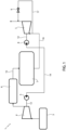
- FIG. 1 a diagram of an engine of a vehicle is illustrated with a forced induction device according to the invention.
- the reference number 1 is used to indicate, overall, a vehicle, specifically a motor vehicle, in particular a sports or racing vehicle.
- the motor vehicle 1 comprises:
- any one or more of the filter 3, intercooler 6, and even the wastegate 9 are entirely optional and can therefore be absent.
- the assembly formed by the compressor 4, the hydraulic motor 5, the turbine 7 and the hydraulic pump 8 is part of a forced induction device for the engine 2.
- hydraulic motor 5 and the hydraulic pump 8 form part of a hydrostatic transmission configured to drive the compressor 4 by means of the power exiting the turbine 7.
- both or at least one of the hydraulic motor 5 and the hydraulic pump 8 is of the variable displacement type.
- the hydraulic pump 8 is a variable displacement pump.
- Variable displacement is understood in this technical field as the quantity of fluid pumped or processed respectively for a complete rotation of the input shaft of the pump 8 or the output shaft of the motor 5.
- both or at least one of the hydraulic motor 5 and the hydraulic pump 8 comprises a movable mechanical member (typically called swashplate), the position or movement of which determines the variable displacement.
- swashplate a movable mechanical member
- displacement defines a control variable of the pump 8 and/or of the motor 5.
- the forced induction device comprises a control unit configured to regulate the displacement of the hydraulic pump 8 or the hydraulic motor 5 or both, namely in particular their respective control variables.
- control unit is configured to control the compressor 4 or more precisely to regulate at least the speed at the output of the hydraulic motor 5, independently of the turbine 7.
- the speed of the compressor 4 and the turbine 7 are directly influenced by the displacement of the motor 5 and the displacement of the pump 8 respectively.
- the hydrostatic transmission defines a continuously variable transmission, namely a transmission that allows continuous regulation of the speed at the transmission output starting from any constant speed at the transmission inlet.
- the transmission ratio of the hydrostatic transmission which connects the turbine 7 to the compressor 4, is continuously variable.
- the hydraulic motor 5 is mechanically connected to the compressor 4 by means of a mechanical transmission, for example comprising or defined by a drive shaft 12, in particular defining an output shaft for the hydraulic motor 5 and an inlet shaft for the compressor 4.
- a mechanical transmission for example comprising or defined by a drive shaft 12, in particular defining an output shaft for the hydraulic motor 5 and an inlet shaft for the compressor 4.
- the compressor 4, or more precisely an impeller thereof has an angular velocity directly depending on or corresponding to the speed at the output of the hydraulic motor 5, in turn, in particular, corresponding to the displacement of the motor 5.
- control unit is configured to control the angular velocity of the compressor 4, in particular by controlling the displacement of the motor 5.
- control unit is also configured to control the turbine 7 or more precisely an output speed thereof.
- control unit controls the turbine 7 by means of a control of the wastegate 9.
- a control of the wastegate 9 This is not limiting, however, since there are many ways of regulating the turbine 7 or the output speed thereof, for example by involving mechanical devices such as slip-control clutches, brakes, and the like.
- the speed of the turbine 7 can also be controlled by controlling the displacement of the pump 8.
- the turbine 7 and the compressor 4 are controllable independently of each other due to the hydrostatic transmission.
- control unit is configured to individually control the output speed from the turbine 7 and the input speed to the compressor 4, namely the angular velocity of the impeller, more in particular controlling the displacement of the motor 5 and the pump 8.
- control unit preferably performs an independent control of the compressor 4 and the turbine 7, for example in a closed loop, for each of the compressor 4 and the turbine 7.
- control unit controls the compressor 4 and the turbine 7 according to respective independent control laws.
- each control law can be based on an optimization of the efficiency of the compressor 4 or the turbine, respectively. More precisely, each control law can be based on the solution to a problem of optimal control, in particular based in turn on maximization of a target function increasing with the performance or efficiency of the compressor 4 or the turbine 7 respectively.
- control unit controls the compressor 4 or more precisely the input speed to the compressor 4 with the sole objective of optimizing intake of the engine 2 according to the required performance (namely torque and power to be delivered by the engine 2); in other words, control of the compressor 4 is solely aimed at optimizing the combustion in the engine 2, namely its performance. Therefore, the control law with which the control unit controls the compressor 4 is based on optimization of the performance of the engine 2.
- control unit solves in general one or more problems of optimal control, namely by optimizing one or more target functions (maximizing or minimizing, based on the type of target function).
- target functions can be various: for example, a target function could be a linear or non-linear combination of the efficiencies of the compressor 4 and the turbine 7, the overall energy expenditure of the engine 2, the difference between actual torque of the engine 2 and a target torque of the engine 2, and similar, in a non-limiting manner.
- the target function or functions are a function of the speed of the compressor 4 and/or the speed of the turbine 7, so that the result of resolution of the problem of optimal control is a speed target for the compressor 4 and a speed target for the turbine 7.
- control unit is configured to determine or comprise (for example, since they are stored) the speed target for the compressor 4 and/or the speed target for the turbine 7.
- the speed targets for the compressor 4 and for the turbine 7 will correspond to target values of the displacement of the motor 5 and/or the pump 8 respectively.
- control unit is configured to control the displacement of the motor 5 and/or the pump 8, namely in a corresponding way the speed of the compressor 4 and/or the turbine 7, by means of respective control laws configured to minimize or reduce the relative differences between the target values and the actual displacements of the motor 5 and/or the pump 8.
- control laws can be in open loop, based on the target values, or in closed loop based on feedback signals of the displacements, which can for example be estimated or determined by appropriate transducers.
- control laws in closed loop could be PI or PID (proportional-integrative or proportional-integrative-derivative) control laws.
- control laws are configured to minimize or reduce the differences between the actual speeds of the compressor 4 and turbine 7 and the relative speed targets.
- the hydraulic motor 5 is hydraulically connected to the hydraulic pump 8 to receive the liquid provided by the latter.
- the connection is made through a duct or hydraulic circuit 14 of the forced induction device.
- the forced induction device comprises an intake line 15 that connects an outlet for the compressed air of the compressor 5 to an intake manifold of the engine 2, in particular passing through the intercooler 6.
- the intake line 15 is configured to supply the intake manifold with the compressed air emitted by the compressor 4.
- the forced induction device comprises an exhaust line 16 that connects an exhaust manifold of the engine 2 to an inlet of the turbine 7.
- the forced induction device further comprises a bypass line 17 connected to the exhaust line 16 upstream of the turbine 7 and having an exhaust termination downstream of the turbine 7.
- the bypass line 17 comprises for example the wastegate 9.
- the wastegate 9 is configured to split the exhaust gas flow through the bypass line 17, thus forcing a portion of the exhaust gases coming from the exhaust manifold of the engine 2 to pass through the turbine 7.
- the control unit is configured to regulate splitting of the flow by means of the wastegate 9.
- the mechanical separation between the turbine 7 and the compressor 4 offers a considerable advantage, in particular due to a clearly increased controllability of the forced induction device compared to a traditional turbocharger.
- the turbine 7 and the compressor 4 can operate in respective independent regimes, thereby maximizing efficiency.
- the forced induction device is without electric machines like electric motors or alternators. This results in a significant advantage in terms of weight, overall dimensions and cost.
- each of the details included in the figures is independent of the other details and is specifically designed to solve specific technical problems in isolation with respect to the other details.
Landscapes
- Engineering & Computer Science (AREA)
- Chemical & Material Sciences (AREA)
- Combustion & Propulsion (AREA)
- Mechanical Engineering (AREA)
- General Engineering & Computer Science (AREA)
- Chemical Kinetics & Catalysis (AREA)
- General Chemical & Material Sciences (AREA)
- Supercharger (AREA)
Abstract
Description
- This patent application claims priority from
Italian patent application no. 102022000026403 filed on December 22, 2022 - The invention concerns a forced induction device for an internal combustion engine.
- It is known that some vehicles are provided with a forced induction engine, namely an internal combustion engine that receives precompressed air in the intake manifold.
- The intake manifold air can be compressed for example by means of a turbocharger, namely a device comprising a turbine and a compressor fitted on the same shaft, so that the turbine can supply power to the compressor.
- The power supplied to the compressor is generated by the turbine by the expansion of at least a portion of the exhaust gases, which is channelled through the turbine.
- The remaining portion of the exhaust gases bypasses the turbine and is directly conveyed towards the after-treatment system of the engine.
- The bypass is typically regulated by a valve commonly known as wastegate.
- In general, although turbochargers are widely used for the forced induction of engines, the need is felt for an improvement in this field.
- In particular, forced induction is an important aspect for determining the efficiency and performance of the engine, hence the need is felt to increase or even optimize efficiency and performance.
- More specifically, the need is felt to improve the known turbochargers, specifically considering also questions relating to overall dimensions, weights and necessary costs.
- An object of the invention is to meet at least one of the above needs, preferably in a simple reliable manner.
- The object is achieved by a forced induction device for an internal combustion engine, as defined in claim 1.
- The dependent claims define particular embodiments of the invention.
- Below, an embodiment of the invention is described for a better understanding thereof by way of non-limiting example and with reference to the attached
figure 1 , in which a diagram of an engine of a vehicle is illustrated with a forced induction device according to the invention. - In
figure 1 , the reference number 1 is used to indicate, overall, a vehicle, specifically a motor vehicle, in particular a sports or racing vehicle. - The motor vehicle 1 comprises:
- an
internal combustion engine 2, - a
filter 3 to filter the air outside the motor vehicle 1, - a
compressor 4 connected to thefilter 3 to receive air at the intake, in particular air at ambient pressure, and configured to supply compressed air at the outlet, - a
hydraulic motor 5 arranged or configured to drive thecompressor 4, - an intercooler 6, arranged or configured to cool the compressed air from the
compressor 4 and to supply the cooled compressed air to theengine 2, - a turbine 7 connected to the
engine 2 to receive a flow of exhaust gases of theengine 2 and configured to expand the exhaust gases, thus generating mechanical power at the outlet, - a
hydraulic pump 8 arranged or configured to be driven by the mechanical power at the outlet of the turbine 7 and to supply a liquid under pressure to thehydraulic motor 5, and - a pressure valve or
wastegate 9, for example of known type, configured to regulate the flow of exhaust gases towards the turbine 7 and a flow of exhaust gases that bypasses the turbine 7. - For example, any one or more of the
filter 3, intercooler 6, and even thewastegate 9 are entirely optional and can therefore be absent. - The assembly formed by the
compressor 4, thehydraulic motor 5, the turbine 7 and thehydraulic pump 8 is part of a forced induction device for theengine 2. - In greater detail, the
hydraulic motor 5 and thehydraulic pump 8 form part of a hydrostatic transmission configured to drive thecompressor 4 by means of the power exiting the turbine 7. - More precisely, both or at least one of the
hydraulic motor 5 and thehydraulic pump 8 is of the variable displacement type. In particular, thehydraulic pump 8 is a variable displacement pump. - Variable displacement is understood in this technical field as the quantity of fluid pumped or processed respectively for a complete rotation of the input shaft of the
pump 8 or the output shaft of themotor 5. - In other words, both or at least one of the
hydraulic motor 5 and thehydraulic pump 8 comprises a movable mechanical member (typically called swashplate), the position or movement of which determines the variable displacement. - Therefore, displacement defines a control variable of the
pump 8 and/or of themotor 5. - Furthermore, the forced induction device comprises a control unit configured to regulate the displacement of the
hydraulic pump 8 or thehydraulic motor 5 or both, namely in particular their respective control variables. - The regulation can be performed for example by means of an actuator controlled by the control unit to move the above-mentioned movable member, thus varying the displacement.
- In this way, in other words, the control unit is configured to control the
compressor 4 or more precisely to regulate at least the speed at the output of thehydraulic motor 5, independently of the turbine 7. - In fact, the speed of the
compressor 4 and the turbine 7 are directly influenced by the displacement of themotor 5 and the displacement of thepump 8 respectively. - The hydrostatic transmission defines a continuously variable transmission, namely a transmission that allows continuous regulation of the speed at the transmission output starting from any constant speed at the transmission inlet. In other words, the transmission ratio of the hydrostatic transmission, which connects the turbine 7 to the
compressor 4, is continuously variable. - The
hydraulic motor 5 is mechanically connected to thecompressor 4 by means of a mechanical transmission, for example comprising or defined by adrive shaft 12, in particular defining an output shaft for thehydraulic motor 5 and an inlet shaft for thecompressor 4. - Therefore, the
compressor 4, or more precisely an impeller thereof, has an angular velocity directly depending on or corresponding to the speed at the output of thehydraulic motor 5, in turn, in particular, corresponding to the displacement of themotor 5. - Consequently, the control unit is configured to control the angular velocity of the
compressor 4, in particular by controlling the displacement of themotor 5. - Furthermore, the control unit is also configured to control the turbine 7 or more precisely an output speed thereof.
- The
hydraulic pump 8 is mechanically connected to the turbine 7 by means of a mechanical transmission, for example comprising or defined by adrive shaft 13, in particular defining an output shaft for the turbine 7 and an inlet shaft for thehydraulic pump 8. - For example, the control unit controls the turbine 7 by means of a control of the
wastegate 9. This is not limiting, however, since there are many ways of regulating the turbine 7 or the output speed thereof, for example by involving mechanical devices such as slip-control clutches, brakes, and the like. - Furthermore, the speed of the turbine 7 can also be controlled by controlling the displacement of the
pump 8. - In practice, the turbine 7 and the
compressor 4 are controllable independently of each other due to the hydrostatic transmission. - In particular, the control unit is configured to individually control the output speed from the turbine 7 and the input speed to the
compressor 4, namely the angular velocity of the impeller, more in particular controlling the displacement of themotor 5 and thepump 8. - More in particular, the control unit preferably performs an independent control of the
compressor 4 and the turbine 7, for example in a closed loop, for each of thecompressor 4 and the turbine 7. - In practice, the control unit controls the
compressor 4 and the turbine 7 according to respective independent control laws. - For example, each control law can be based on an optimization of the efficiency of the
compressor 4 or the turbine, respectively. More precisely, each control law can be based on the solution to a problem of optimal control, in particular based in turn on maximization of a target function increasing with the performance or efficiency of thecompressor 4 or the turbine 7 respectively. - Alternatively or additionally, the control unit controls the
compressor 4 or more precisely the input speed to thecompressor 4 with the sole objective of optimizing intake of theengine 2 according to the required performance (namely torque and power to be delivered by the engine 2); in other words, control of thecompressor 4 is solely aimed at optimizing the combustion in theengine 2, namely its performance. Therefore, the control law with which the control unit controls thecompressor 4 is based on optimization of the performance of theengine 2. - In practice, the control unit solves in general one or more problems of optimal control, namely by optimizing one or more target functions (maximizing or minimizing, based on the type of target function). The possible target functions can be various: for example, a target function could be a linear or non-linear combination of the efficiencies of the
compressor 4 and the turbine 7, the overall energy expenditure of theengine 2, the difference between actual torque of theengine 2 and a target torque of theengine 2, and similar, in a non-limiting manner. - The target function or functions are a function of the speed of the
compressor 4 and/or the speed of the turbine 7, so that the result of resolution of the problem of optimal control is a speed target for thecompressor 4 and a speed target for the turbine 7. - More generally, the control unit is configured to determine or comprise (for example, since they are stored) the speed target for the
compressor 4 and/or the speed target for the turbine 7. - The speed targets for the
compressor 4 and for the turbine 7 will correspond to target values of the displacement of themotor 5 and/or thepump 8 respectively. - Therefore, the control unit is configured to control the displacement of the
motor 5 and/or thepump 8, namely in a corresponding way the speed of thecompressor 4 and/or the turbine 7, by means of respective control laws configured to minimize or reduce the relative differences between the target values and the actual displacements of themotor 5 and/or thepump 8. For example, the control laws can be in open loop, based on the target values, or in closed loop based on feedback signals of the displacements, which can for example be estimated or determined by appropriate transducers. For example, the control laws in closed loop could be PI or PID (proportional-integrative or proportional-integrative-derivative) control laws. - Correspondingly and implicitly, the control laws are configured to minimize or reduce the differences between the actual speeds of the
compressor 4 and turbine 7 and the relative speed targets. - With greater reference to
figure 1 , thehydraulic motor 5 is hydraulically connected to thehydraulic pump 8 to receive the liquid provided by the latter. In particular, the connection is made through a duct orhydraulic circuit 14 of the forced induction device. - Furthermore, the forced induction device comprises an
intake line 15 that connects an outlet for the compressed air of thecompressor 5 to an intake manifold of theengine 2, in particular passing through the intercooler 6. - In practice, the
intake line 15 is configured to supply the intake manifold with the compressed air emitted by thecompressor 4. - In addition, the forced induction device comprises an exhaust line 16 that connects an exhaust manifold of the
engine 2 to an inlet of the turbine 7. - Preferably, the forced induction device further comprises a
bypass line 17 connected to the exhaust line 16 upstream of the turbine 7 and having an exhaust termination downstream of the turbine 7. - The
bypass line 17 comprises for example thewastegate 9. Thewastegate 9 is configured to split the exhaust gas flow through thebypass line 17, thus forcing a portion of the exhaust gases coming from the exhaust manifold of theengine 2 to pass through the turbine 7. - The control unit is configured to regulate splitting of the flow by means of the
wastegate 9. - From the above, the advantages of the forced induction device according to the invention are evident.
- The mechanical separation between the turbine 7 and the
compressor 4 offers a considerable advantage, in particular due to a clearly increased controllability of the forced induction device compared to a traditional turbocharger. - In fact, since they are uncoupled, the turbine 7 and the
compressor 4 can operate in respective independent regimes, thereby maximizing efficiency. - Furthermore, the use of a hydrostatic transmission is particularly advantageous, especially with respect to the use of electric components. The forced induction device is without electric machines like electric motors or alternators. This results in a significant advantage in terms of weight, overall dimensions and cost.
- Lastly it is clear that modifications and variations that do not depart from the protective scope defined by the claims can be made to the forced induction device according to the invention.
- In particular, each of the details included in the figures is independent of the other details and is specifically designed to solve specific technical problems in isolation with respect to the other details.
Claims (9)
- - A forced induction device for an internal combustion engine (2), the device comprising- a compressor (4) operable to provide compressed air,- an intake line (15) configured to supply an intake manifold of the internal combustion engine (2) with the compressed air provided by the compressor (4),- a turbine (7) configured to generate mechanical power through expansion of at least a portion of exhaust gases of the internal combustion engine (2),- an exhaust line (16) configured to supply the turbine (7) with the exhaust gas portion coming from an exhaust manifold of the internal combustion engine (2),
characterized by further comprising a hydrostatic transmission (5, 8, 14) configured to drive the compressor (4) by means of the mechanical power generated by the turbine (7). - - The forced induction device according to claim 1, wherein the hydrostatic transmission comprises- a hydraulic pump (8) coupled to the turbine (7), so that the mechanical power generated by the turbine (7) drives the hydraulic pump (8), and configured to provide a liquid under pressure, and- a hydraulic motor (5) hydraulically connected to the hydraulic pump (8) to receive the liquid under pressure provided by the hydraulic pump (8) and coupled to the compressor (4) to drive the compressor (4) by means of the liquid under pressure received from the hydraulic pump (8).
- - The forced induction device according to claim 2, wherein both or at least one of the hydraulic pump (8) and the hydraulic motor (5) is of the variable displacement type.
- - The forced induction device according to claim 2 or 3, further comprising a control unit configured to control the hydraulic motor (5) and the hydraulic pump (8), thereby consequently controlling the compressor (4) independently of the turbine (7).
- - The forced induction device according to claim 4, wherein the control unit is configured to control the variable displacement of the hydraulic motor (5) and/or of the hydraulic pump (8).
- - The forced induction device according to claim 4 or 5, wherein the control unit is configured to control the compressor (4) through the hydraulic motor (5) and/or to control the turbine (7) according to respective independent control laws based on an optimization of the respective efficiencies of the compressor (4) and of the turbine (7), respectively.
- - The forced induction device according to claim 4 or 5, wherein the control unit is configured to control the compressor (4) through the hydraulic motor (5) according to a control law based on an optimization of the performances of the internal combustion engine (2).
- - An assembly comprising an internal combustion engine (2) and a forced induction device according to any one of the preceding claims, wherein the intake line (15) connects an air outlet of the compressor (4) to the intake manifold, and wherein the exhaust line (16) connects the exhaust manifold to an inlet of the turbine (7).
- - A motor vehicle (1) comprising the assembly according to claim 8.
Applications Claiming Priority (1)
| Application Number | Priority Date | Filing Date | Title |
|---|---|---|---|
| IT202200026403 | 2022-12-22 |
Publications (2)
| Publication Number | Publication Date |
|---|---|
| EP4390083A1 true EP4390083A1 (en) | 2024-06-26 |
| EP4390083B1 EP4390083B1 (en) | 2025-07-02 |
Family
ID=85462261
Family Applications (1)
| Application Number | Title | Priority Date | Filing Date |
|---|---|---|---|
| EP23217109.0A Active EP4390083B1 (en) | 2022-12-22 | 2023-12-15 | Forced induction device for an internal combustion engine |
Country Status (2)
| Country | Link |
|---|---|
| US (1) | US12173641B2 (en) |
| EP (1) | EP4390083B1 (en) |
Families Citing this family (1)
| Publication number | Priority date | Publication date | Assignee | Title |
|---|---|---|---|---|
| US20250244203A1 (en) * | 2024-01-26 | 2025-07-31 | Pratt & Whitney Canada Corp. | System and method for detecting a mechanical transmission failure |
Citations (4)
| Publication number | Priority date | Publication date | Assignee | Title |
|---|---|---|---|---|
| DE1751941A1 (en) * | 1968-08-22 | 1970-09-17 | Kickbusch Dipl Ing Ernst | Internal combustion engine with supercharging by exhaust gas turbine and displacement charger |
| DE19732543A1 (en) * | 1997-07-29 | 1999-02-04 | Man B & W Diesel Ag | Exhaust gas turbocharger system for internal combustion engines |
| DE19924918A1 (en) * | 1999-05-31 | 2000-12-07 | Volkswagen Ag | Exhaust turbo charger with energy accumulator and energy recovery has drive unit with energy accumulator to store exhaust energy and supply movement energy to compressor shaft |
| US7958727B2 (en) * | 2005-12-29 | 2011-06-14 | Honeywell International Inc. | Electric boost compressor and turbine generator system |
Family Cites Families (4)
| Publication number | Priority date | Publication date | Assignee | Title |
|---|---|---|---|---|
| US8915082B2 (en) * | 2011-02-03 | 2014-12-23 | Ford Global Technologies, Llc | Regenerative assisted turbocharger system |
| JP5587859B2 (en) * | 2011-12-28 | 2014-09-10 | 三菱重工業株式会社 | Electric supercharger |
| IT201700004557A1 (en) * | 2017-01-17 | 2018-07-17 | Ferrari Spa | METHOD OF CONTROL OF A TURBOCHARGER PROVIDED WITH ELECTRIC IMPLEMENTATION IN AN OVERALLY OVER-COMBUSTION INTERNAL COMBUSTION ENGINE |
| US11566568B2 (en) * | 2021-03-19 | 2023-01-31 | Ford Global Technologies, Llc | Valve timing modulation for EGR balancing |
-
2023
- 2023-12-15 EP EP23217109.0A patent/EP4390083B1/en active Active
- 2023-12-19 US US18/544,844 patent/US12173641B2/en active Active
Patent Citations (4)
| Publication number | Priority date | Publication date | Assignee | Title |
|---|---|---|---|---|
| DE1751941A1 (en) * | 1968-08-22 | 1970-09-17 | Kickbusch Dipl Ing Ernst | Internal combustion engine with supercharging by exhaust gas turbine and displacement charger |
| DE19732543A1 (en) * | 1997-07-29 | 1999-02-04 | Man B & W Diesel Ag | Exhaust gas turbocharger system for internal combustion engines |
| DE19924918A1 (en) * | 1999-05-31 | 2000-12-07 | Volkswagen Ag | Exhaust turbo charger with energy accumulator and energy recovery has drive unit with energy accumulator to store exhaust energy and supply movement energy to compressor shaft |
| US7958727B2 (en) * | 2005-12-29 | 2011-06-14 | Honeywell International Inc. | Electric boost compressor and turbine generator system |
Also Published As
| Publication number | Publication date |
|---|---|
| US12173641B2 (en) | 2024-12-24 |
| US20240209772A1 (en) | 2024-06-27 |
| EP4390083B1 (en) | 2025-07-02 |
Similar Documents
| Publication | Publication Date | Title |
|---|---|---|
| US4083188A (en) | Engine turbocharger system | |
| US6205786B1 (en) | Engine having increased boost at low engine speeds | |
| EP2494173B1 (en) | Control strategy for an engine | |
| US6256993B1 (en) | Motor-assisted variable geometry turbocharging system | |
| EP0765436B1 (en) | Arrangement for regulating the engine braking effect of a combustion engine | |
| US3570240A (en) | Supercharging apparatus for diesel and multifuel engines | |
| CN103547326A (en) | Heat recovery device | |
| EP4390083B1 (en) | Forced induction device for an internal combustion engine | |
| US3208213A (en) | Supercharger for an internal combustion engine | |
| US7509806B2 (en) | Method for optimizing the utilization ratio in a drive unit and drive unit | |
| EP2341225A1 (en) | Method for controlling a turbocompound engine apparatus | |
| EP4403759A1 (en) | Propulsion assembly for a motor vehicle | |
| CN107002580B (en) | Method and device for regulating the boost pressure in an internal combustion engine by means of a pressure wave supercharger | |
| US3382855A (en) | Torque converters and power plants | |
| US11629612B2 (en) | System for feeding operating gas to a drive of a motor vehicle | |
| US6883322B2 (en) | System and method for turbocharger control | |
| US3490229A (en) | Turbine-powered prime mover | |
| EP2156031B1 (en) | Turbocharger with adjustable throat | |
| GB1117106A (en) | Fuel-injection type internal combustion engine | |
| US7340896B2 (en) | Method for regulating the turbine power of a turbo in an internal combustion engine | |
| SU727867A1 (en) | I.c.engine supercharging arrangement | |
| CN121701331A (en) | Engine assembly and control method for motor vehicles |
Legal Events
| Date | Code | Title | Description |
|---|---|---|---|
| PUAI | Public reference made under article 153(3) epc to a published international application that has entered the european phase |
Free format text: ORIGINAL CODE: 0009012 |
|
| STAA | Information on the status of an ep patent application or granted ep patent |
Free format text: STATUS: THE APPLICATION HAS BEEN PUBLISHED |
|
| AK | Designated contracting states |
Kind code of ref document: A1 Designated state(s): AL AT BE BG CH CY CZ DE DK EE ES FI FR GB GR HR HU IE IS IT LI LT LU LV MC ME MK MT NL NO PL PT RO RS SE SI SK SM TR |
|
| STAA | Information on the status of an ep patent application or granted ep patent |
Free format text: STATUS: REQUEST FOR EXAMINATION WAS MADE |
|
| 17P | Request for examination filed |
Effective date: 20241224 |
|
| GRAP | Despatch of communication of intention to grant a patent |
Free format text: ORIGINAL CODE: EPIDOSNIGR1 |
|
| STAA | Information on the status of an ep patent application or granted ep patent |
Free format text: STATUS: GRANT OF PATENT IS INTENDED |
|
| INTG | Intention to grant announced |
Effective date: 20250131 |
|
| GRAS | Grant fee paid |
Free format text: ORIGINAL CODE: EPIDOSNIGR3 |
|
| GRAA | (expected) grant |
Free format text: ORIGINAL CODE: 0009210 |
|
| STAA | Information on the status of an ep patent application or granted ep patent |
Free format text: STATUS: THE PATENT HAS BEEN GRANTED |
|
| AK | Designated contracting states |
Kind code of ref document: B1 Designated state(s): AL AT BE BG CH CY CZ DE DK EE ES FI FR GB GR HR HU IE IS IT LI LT LU LV MC ME MK MT NL NO PL PT RO RS SE SI SK SM TR |
|
| REG | Reference to a national code |
Ref country code: GB Ref legal event code: FG4D |
|
| REG | Reference to a national code |
Ref country code: CH Ref legal event code: EP |
|
| REG | Reference to a national code |
Ref country code: DE Ref legal event code: R096 Ref document number: 602023004531 Country of ref document: DE |
|
| REG | Reference to a national code |
Ref country code: IE Ref legal event code: FG4D |
|
| REG | Reference to a national code |
Ref country code: NL Ref legal event code: MP Effective date: 20250702 |
|
| PG25 | Lapsed in a contracting state [announced via postgrant information from national office to epo] |
Ref country code: PT Free format text: LAPSE BECAUSE OF FAILURE TO SUBMIT A TRANSLATION OF THE DESCRIPTION OR TO PAY THE FEE WITHIN THE PRESCRIBED TIME-LIMIT Effective date: 20251103 |
|
| PG25 | Lapsed in a contracting state [announced via postgrant information from national office to epo] |
Ref country code: NL Free format text: LAPSE BECAUSE OF FAILURE TO SUBMIT A TRANSLATION OF THE DESCRIPTION OR TO PAY THE FEE WITHIN THE PRESCRIBED TIME-LIMIT Effective date: 20250702 |
|
| REG | Reference to a national code |
Ref country code: AT Ref legal event code: MK05 Ref document number: 1809458 Country of ref document: AT Kind code of ref document: T Effective date: 20250702 |
|
| PG25 | Lapsed in a contracting state [announced via postgrant information from national office to epo] |
Ref country code: IS Free format text: LAPSE BECAUSE OF FAILURE TO SUBMIT A TRANSLATION OF THE DESCRIPTION OR TO PAY THE FEE WITHIN THE PRESCRIBED TIME-LIMIT Effective date: 20251102 |
|
| PG25 | Lapsed in a contracting state [announced via postgrant information from national office to epo] |
Ref country code: NO Free format text: LAPSE BECAUSE OF FAILURE TO SUBMIT A TRANSLATION OF THE DESCRIPTION OR TO PAY THE FEE WITHIN THE PRESCRIBED TIME-LIMIT Effective date: 20251002 |
|
| REG | Reference to a national code |
Ref country code: LT Ref legal event code: MG9D |
|
| PG25 | Lapsed in a contracting state [announced via postgrant information from national office to epo] |
Ref country code: AT Free format text: LAPSE BECAUSE OF FAILURE TO SUBMIT A TRANSLATION OF THE DESCRIPTION OR TO PAY THE FEE WITHIN THE PRESCRIBED TIME-LIMIT Effective date: 20250702 |
|
| PG25 | Lapsed in a contracting state [announced via postgrant information from national office to epo] |
Ref country code: FI Free format text: LAPSE BECAUSE OF FAILURE TO SUBMIT A TRANSLATION OF THE DESCRIPTION OR TO PAY THE FEE WITHIN THE PRESCRIBED TIME-LIMIT Effective date: 20250702 |
|
| PG25 | Lapsed in a contracting state [announced via postgrant information from national office to epo] |
Ref country code: HR Free format text: LAPSE BECAUSE OF FAILURE TO SUBMIT A TRANSLATION OF THE DESCRIPTION OR TO PAY THE FEE WITHIN THE PRESCRIBED TIME-LIMIT Effective date: 20250702 |
|
| PGFP | Annual fee paid to national office [announced via postgrant information from national office to epo] |
Ref country code: FR Payment date: 20251223 Year of fee payment: 3 |
|
| PG25 | Lapsed in a contracting state [announced via postgrant information from national office to epo] |
Ref country code: GR Free format text: LAPSE BECAUSE OF FAILURE TO SUBMIT A TRANSLATION OF THE DESCRIPTION OR TO PAY THE FEE WITHIN THE PRESCRIBED TIME-LIMIT Effective date: 20251003 |
|
| PG25 | Lapsed in a contracting state [announced via postgrant information from national office to epo] |
Ref country code: CZ Free format text: LAPSE BECAUSE OF FAILURE TO SUBMIT A TRANSLATION OF THE DESCRIPTION OR TO PAY THE FEE WITHIN THE PRESCRIBED TIME-LIMIT Effective date: 20250702 Ref country code: SE Free format text: LAPSE BECAUSE OF FAILURE TO SUBMIT A TRANSLATION OF THE DESCRIPTION OR TO PAY THE FEE WITHIN THE PRESCRIBED TIME-LIMIT Effective date: 20250702 |
|
| PG25 | Lapsed in a contracting state [announced via postgrant information from national office to epo] |
Ref country code: LV Free format text: LAPSE BECAUSE OF FAILURE TO SUBMIT A TRANSLATION OF THE DESCRIPTION OR TO PAY THE FEE WITHIN THE PRESCRIBED TIME-LIMIT Effective date: 20250702 |
|
| PG25 | Lapsed in a contracting state [announced via postgrant information from national office to epo] |
Ref country code: BG Free format text: LAPSE BECAUSE OF FAILURE TO SUBMIT A TRANSLATION OF THE DESCRIPTION OR TO PAY THE FEE WITHIN THE PRESCRIBED TIME-LIMIT Effective date: 20250702 Ref country code: PL Free format text: LAPSE BECAUSE OF FAILURE TO SUBMIT A TRANSLATION OF THE DESCRIPTION OR TO PAY THE FEE WITHIN THE PRESCRIBED TIME-LIMIT Effective date: 20250702 |
|
| PG25 | Lapsed in a contracting state [announced via postgrant information from national office to epo] |
Ref country code: RS Free format text: LAPSE BECAUSE OF FAILURE TO SUBMIT A TRANSLATION OF THE DESCRIPTION OR TO PAY THE FEE WITHIN THE PRESCRIBED TIME-LIMIT Effective date: 20251002 |
|
| PG25 | Lapsed in a contracting state [announced via postgrant information from national office to epo] |
Ref country code: ES Free format text: LAPSE BECAUSE OF FAILURE TO SUBMIT A TRANSLATION OF THE DESCRIPTION OR TO PAY THE FEE WITHIN THE PRESCRIBED TIME-LIMIT Effective date: 20250702 |
|
| PG25 | Lapsed in a contracting state [announced via postgrant information from national office to epo] |
Ref country code: RO Free format text: LAPSE BECAUSE OF FAILURE TO SUBMIT A TRANSLATION OF THE DESCRIPTION OR TO PAY THE FEE WITHIN THE PRESCRIBED TIME-LIMIT Effective date: 20250702 |
|
| PG25 | Lapsed in a contracting state [announced via postgrant information from national office to epo] |
Ref country code: SM Free format text: LAPSE BECAUSE OF FAILURE TO SUBMIT A TRANSLATION OF THE DESCRIPTION OR TO PAY THE FEE WITHIN THE PRESCRIBED TIME-LIMIT Effective date: 20250702 |
|
| PG25 | Lapsed in a contracting state [announced via postgrant information from national office to epo] |
Ref country code: DK Free format text: LAPSE BECAUSE OF FAILURE TO SUBMIT A TRANSLATION OF THE DESCRIPTION OR TO PAY THE FEE WITHIN THE PRESCRIBED TIME-LIMIT Effective date: 20250702 |
|
| PGFP | Annual fee paid to national office [announced via postgrant information from national office to epo] |
Ref country code: DE Payment date: 20251229 Year of fee payment: 3 |
|
| PGFP | Annual fee paid to national office [announced via postgrant information from national office to epo] |
Ref country code: IT Payment date: 20251231 Year of fee payment: 3 |
|
| PG25 | Lapsed in a contracting state [announced via postgrant information from national office to epo] |
Ref country code: SK Free format text: LAPSE BECAUSE OF FAILURE TO SUBMIT A TRANSLATION OF THE DESCRIPTION OR TO PAY THE FEE WITHIN THE PRESCRIBED TIME-LIMIT Effective date: 20250702 Ref country code: EE Free format text: LAPSE BECAUSE OF FAILURE TO SUBMIT A TRANSLATION OF THE DESCRIPTION OR TO PAY THE FEE WITHIN THE PRESCRIBED TIME-LIMIT Effective date: 20250702 |