EP4390078A2 - Boat propulsion device and outboard motor - Google Patents
Boat propulsion device and outboard motor Download PDFInfo
- Publication number
- EP4390078A2 EP4390078A2 EP23202931.4A EP23202931A EP4390078A2 EP 4390078 A2 EP4390078 A2 EP 4390078A2 EP 23202931 A EP23202931 A EP 23202931A EP 4390078 A2 EP4390078 A2 EP 4390078A2
- Authority
- EP
- European Patent Office
- Prior art keywords
- cooling water
- pump
- shaft
- propulsion device
- boat propulsion
- Prior art date
- Legal status (The legal status is an assumption and is not a legal conclusion. Google has not performed a legal analysis and makes no representation as to the accuracy of the status listed.)
- Granted
Links
Images




Classifications
-
- F—MECHANICAL ENGINEERING; LIGHTING; HEATING; WEAPONS; BLASTING
- F01—MACHINES OR ENGINES IN GENERAL; ENGINE PLANTS IN GENERAL; STEAM ENGINES
- F01P—COOLING OF MACHINES OR ENGINES IN GENERAL; COOLING OF INTERNAL-COMBUSTION ENGINES
- F01P3/00—Liquid cooling
- F01P3/20—Cooling circuits not specific to a single part of engine or machine
- F01P3/202—Cooling circuits not specific to a single part of engine or machine for outboard marine engines
-
- B—PERFORMING OPERATIONS; TRANSPORTING
- B63—SHIPS OR OTHER WATERBORNE VESSELS; RELATED EQUIPMENT
- B63H—MARINE PROPULSION OR STEERING
- B63H20/00—Outboard propulsion units, e.g. outboard motors or Z-drives; Arrangements thereof on vessels
- B63H20/28—Arrangements, apparatus and methods for handling cooling-water in outboard drives, e.g. cooling-water intakes
-
- B—PERFORMING OPERATIONS; TRANSPORTING
- B63—SHIPS OR OTHER WATERBORNE VESSELS; RELATED EQUIPMENT
- B63H—MARINE PROPULSION OR STEERING
- B63H20/00—Outboard propulsion units, e.g. outboard motors or Z-drives; Arrangements thereof on vessels
- B63H20/28—Arrangements, apparatus and methods for handling cooling-water in outboard drives, e.g. cooling-water intakes
- B63H20/285—Cooling-water intakes
-
- F—MECHANICAL ENGINEERING; LIGHTING; HEATING; WEAPONS; BLASTING
- F01—MACHINES OR ENGINES IN GENERAL; ENGINE PLANTS IN GENERAL; STEAM ENGINES
- F01P—COOLING OF MACHINES OR ENGINES IN GENERAL; COOLING OF INTERNAL-COMBUSTION ENGINES
- F01P5/00—Pumping cooling-air or liquid coolants
- F01P5/10—Pumping liquid coolant; Arrangements of coolant pumps
-
- F—MECHANICAL ENGINEERING; LIGHTING; HEATING; WEAPONS; BLASTING
- F01—MACHINES OR ENGINES IN GENERAL; ENGINE PLANTS IN GENERAL; STEAM ENGINES
- F01P—COOLING OF MACHINES OR ENGINES IN GENERAL; COOLING OF INTERNAL-COMBUSTION ENGINES
- F01P11/00—Component parts, details, or accessories not provided for in, or of interest apart from, groups F01P1/00 - F01P9/00
- F01P11/06—Cleaning; Combating corrosion
- F01P2011/061—Cleaning or combating corrosion using filters
-
- F—MECHANICAL ENGINEERING; LIGHTING; HEATING; WEAPONS; BLASTING
- F01—MACHINES OR ENGINES IN GENERAL; ENGINE PLANTS IN GENERAL; STEAM ENGINES
- F01P—COOLING OF MACHINES OR ENGINES IN GENERAL; COOLING OF INTERNAL-COMBUSTION ENGINES
- F01P2050/00—Applications
- F01P2050/02—Marine engines
- F01P2050/04—Marine engines using direct cooling
Definitions
- the present invention relates to a boat propulsion device and an outboard motor with a boat propulsion device.
- outboard motors are equipped with a water pump for pumping cooling water to cool the engine.
- the water pump consists of an impeller or the like attached to a drive shaft. When the engine is driven, the impeller rotates together with the rotation of the drive shaft, and cooling water is pumped into the engine (see JP 2015-145137 A ).
- An outboard motor is an outboard motor to be mounted on a hull, the outboard motor including: a cooling water flow path having an intake port for taking in cooling water from the outside and through which cooling water flows; and a water pump including an impeller and a pump shaft rotating together with the impeller to pump the cooling water into the cooling water flow path, wherein an inlet channel of the cooling water flow path from the intake port to the water pump extends along the rotation axis of the pump shaft in front of the water pump, and a filter member that allows the passage of the cooling water and inhibits entry of foreign objects is placed inside the inlet channel.
- the cooling water taken from outside flows from the front to the impeller attached to the pump shaft so that the cooling water can be pumped efficiently.
- This configuration also suppresses damage to the water pump caused by foreign objects colliding with the water pump.
- the outboard motor may further include a drive unit, a drive shaft rotationally driven by the drive unit, a propeller, and a propeller shaft that rotates together with the propeller, the drive shaft may be rotatable in both a forward direction (first rotation direction) and a reverse direction (second rotation direction), which is opposite to the forward direction, and the water pump may be a non-volumetric pump.
- the drive shaft which can rotate in both forward and reverse directions, eliminates the need for a clutch mechanism such as a dog clutch, thereby providing a relatively large space around the propeller shaft.
- This space can be used to accommodate the water pump, eliminating the need for a larger outboard motor and optimizing the arrangement of the components necessary to transport cooling water.
- the non-volumetric pump since the non-volumetric pump has no restriction on the direction of rotation, it is suitable as a pump connected to a drive shaft that can rotate in both the forward and reverse directions.
- the drive unit may be an electric motor driven by electricity supplied from a power source.
- the water pump may be a centrifugal pump.
- the water pump may be located on the rotation axis of the propeller shaft.
- This configuration allows the water pump to be positioned without protruding sideways from the rotation axis of the propeller shaft, thereby avoiding a reduction in the propulsive force of the hull.
- the filter member may be made of resin.
- the filter member may be made of glass fiber reinforced plastic.
- the filter member compared to the case where the filter member is made of resin that does not contain glass fibers, the filter member can be made stronger, and thus the filter member can be suppressed from being damaged by collisions with foreign objects while cruising, collisions with a shore while anchoring, and the like.
- the filter member may include a holding member having a through hole and fixed inside the inlet channel, and a filter body held inside the through hole that allows the passage of the cooling water and inhibits entry of foreign objects, and the holding member may made of resin, and the filter body may be made of metal.
- the holding member of the filter member that is in contact with the member constituting the inlet channel is made of resin, it is possible to suppress the filter member from corroding and adhering to the member constituting the inlet channel.
- the filter body is made of metal, the filter portion can be made stronger compared to the case where the whole of the filter member is made of resin, and thus the filter portion can be suppressed from being damaged by collisions with foreign objects while cruising, collisions with a shore while anchoring, and the like.
- An boat propulsion device is a boat propulsion device provided on a hull, the boat propulsion device including: a cooling water flow path having an intake port for taking in cooling water from the outside and through which cooling water flows; and a water pump including an impeller and a pump shaft rotating together with the impeller to pump the cooling water into the cooling water flow path, wherein a filter member that allows the passage of the cooling water and inhibits entry of foreign objects is placed at the intake port, and the filter member is placed on the rotation axis of the pump shaft in front of the water pump.
- cooling water taken in from the outside flows in from the front to the impeller attached to the pump shaft, thus enabling efficient pumping of the cooling water.
- This configuration also suppresses damage to the water pump caused by foreign objects colliding with the water pump.
- Embodiment 1 will be described with reference to FIGS. 1 to 4 .
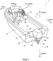
- a boat 1 of Embodiment 1 is equipped with a hull 10 and an outboard motor 100 (an example of the boat propulsion device), as shown in FIG. 1.
- FIG. 1 and other drawings described below show arrows representing each direction with respect to the position of the boat 1. More specifically, each figure shows arrows representing front (FRONT), rear (REAR), left (LEFT), right (RIGHT), upper (UPPER), and lower (LOWER) directions, respectively.
- the front-rear direction, left-right direction, and upper-lower direction (vertical direction) are orthogonal to each other.
- the hull 10 is a part of the boat 1 for occupants to ride. As shown in FIG. 1 , the hull 10 has a hull body 12 having a living space 11, a pilot seat 16 installed in the living space 11, and an operating device 17 installed near the pilot seat 16.
- the operating device 17 is a device for maneuvering the boat and includes, e.g., a steering wheel, a shift throttle lever, a joystick, a monitor, and an input device.
- the hull 10 also has a partition wall 13 that partitions the rear end of the living space 11 and a transom 14 positioned at the rear end of the hull 10. In the front-rear direction, there is a space 15 between the transom 14 and the partition wall 13.
- the outboard motor 100 is a device that generates thrust to propel the boat 1.
- the outboard motor 100 in this embodiment is an electric outboard motor driven by an electric motor 120 (an example of a drive unit).
- the outboard motor 100 in the reference attitude will be described below unless otherwise specified.
- the reference attitude is the attitude of the outboard motor 100 when the boat 1 is cruising (attitude shown in FIG. 1 ), in which the rotation axis Ad of the drive shaft 130 (described below) extends in the upper-lower direction and the rotation axis Apr of the propeller shaft 140 extends in the front-rear direction.
- the front-rear direction, the left-right direction, and the upper-lower direction are defined based on the outboard motor 100 in the reference attitude.
- the outboard motor 100 is attached to the transom 14 located at the rear (stern) of the hull 10.
- the outboard motor 100 has an outboard motor main body 110 and a suspension device 150.
- the outboard motor main body 110 includes a cowl 114, a casing 116, an electric motor 120, a drive shaft 130, a propeller 141, a propeller shaft 140, a cooling water flow path 200, a water pump 210, a first gear mechanism 180, a second gear mechanism 190, and an inlet 310 (an example of the filter member).
- the cowl 114 is a housing located on top of the outboard motor main body 110.
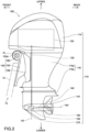
- the casing 116 includes an upper case 116a and a lower case 116b, as shown in FIG. 2 .
- the upper case 116a is a housing located below the cowl 114.
- the lower case 116b is a housing located below the upper case 116a.
- the lower case 116b has a gear chamber 118 that stores oil therein and houses the first gear mechanism 180 and the second gear mechanism 190, as shown in FIG. 4 .
- the electric motor 120 is driven by electric power supplied from a battery (power source).
- the electric motor 120 includes a rotor including a permanent magnet, a stator including a coil to which the battery power is supplied, and a motor housing that houses the rotor and stator.
- the electric motor 120 is located inside the cowl 114.
- the battery may be located inside the cowl 114 or inside the hull 10.
- the drive shaft 130 is a rod-shaped member extending downward from the electric motor 120 and housed within the casing 116, as shown in FIG. 2 .
- the drive shaft 130 is arranged in an attitude in which its rotation axis Ad extends in the upper-lower direction.
- the drive shaft 130 has a rod-shaped main shaft 131 and an extension shaft 132 extending from the tip of the main shaft 131 opposite to the electric motor 120 (lower end in FIG. 4 ).
- the main shaft 131 includes a constant-diameter shaft 131A extending from the electric motor 120, which is a round rod of constant thickness, and a reduced-diameter shaft 131B connecting the constant-diameter shaft 131A and the extension shaft 132.
- the extension shaft 132 extends coaxially with the main shaft 131 and has a round rod shape with a smaller diameter than the constant-diameter shaft 131A.
- the constant-diameter shaft 131A, the reduced-diameter shaft 131B, and the extension shaft 132 are arranged coaxially.
- the drive shaft 130 rotates around the rotation axis Ad by the rotational driving force of the electric motor 120. Since the electric motor 120 can rotate in both forward and reverse directions, the drive shaft 130 can also rotate around the rotation axis line Ad in both forward direction (first rotation direction) to move the boat 1 forward and reverse direction (second rotation direction) to move the boat 1 backward, which is opposite to the forward direction, according to the rotational driving direction of the electric motor 120.
- the propeller 141 is a rotating body having a plurality of blades.
- the propeller 141 generates thrust by rotation.
- the propeller shaft 140 is a rod-shaped member and extends in the front-rear direction inside the lower case 116b, as shown in FIGS. 2 , 3 , and 4 .
- the propeller shaft 140 is rotatably supported by the lower case 116b via a bearing 142.
- the rear end of the propeller shaft 140 protrudes rearwardly from the lower case 116b, and the propeller 141 is attached to this rear end. As the propeller shaft 140 rotates around the rotation axis Apr, the propeller 141 also rotates.
- the cooling water flow path 200 is located inside the outboard motor main body 110.
- the cooling water flow path 200 is a channel through which cooling water (seawater, lake water, and river water, among others) taken from outside the outboard motor 100 flows.
- the cooling water flow path 200 has an intake port 201 that opens on the outer surface of the lower case 116b for taking cooling water into the interior and a drain port 202 that also opens on the outer surface of the lower case 116b for discharging cooling water to the exterior; the cooling water flow path 200 extends from the intake port 201 through the periphery of the electric motor 120 to the drain port 202.
- the intake port 201 is located below the waterline when the boat 1 is cruising, i.e., when the outboard motor 100 is in the reference attitude.
- the intake port 201 is open at the front end of the lower case 116b.
- a portion of the cooling water flow path 200 is a pump chamber 203.
- the pump chamber 203 is located in front of the gear chamber 118 in the lower case 116b and is separated from the gear chamber 118 by a partition member 220.
- the partition member 220 has a shaft hole 221 that is connected to the pump chamber 203 and the gear chamber 118.
- the water pump 210 is a non-volumetric pump having an impeller 211 and a pump shaft 212 that rotates together with the impeller 211, as shown in FIG. 4 .
- a centrifugal pump is exemplified as the water pump 210.
- the impeller 211 is a rotating body having a plurality of blades and is located inside the pump chamber 203.
- the pump shaft 212 is a rod-shaped member and extends in a front-rear direction.
- the pump shaft 212 is inserted into the shaft hole 221 and is supported by the partition member 220 in a rotatable manner via a bearing 213.
- the rotation axis Apn of the pump shaft 212 coincides with the rotation axis Apr of the propeller shaft 140.
- the front end of the pump shaft 212 is located inside the pump chamber 203, where the impeller 211 is mounted.
- the water pump 210 (specifically, the pump shaft 212 and impeller 211) is located on the rotation axis Apr of the propeller shaft 140.
- the impeller 211 also rotates.
- the rear end of the pump shaft 212 is located inside the gear chamber 118.
- a plurality of seal members 230 are arranged on the outer surface of the pump shaft 212 to fill the gap between the inner surface of the shaft hole 221 and the pump shaft 212.
- Each seal member 230 is circular in shape, is composed of a material such as rubber having rubber elasticity, and encircles the pump shaft 212 all the way around.
- the plurality of seal members 230 are arranged in line along the rotation axis Apn of the pump shaft 212. These seal members 230 prevent cooling water flowing into the pump chamber 203 from entering the gear chamber 118 through the gap between the inner circumferential surface of the shaft hole 221 and the pump shaft 212.
- the portion of the cooling water flow path 200 from the intake port 201 to the water pump 210 i.e., the portion located between the intake port 201 and the pump chamber 203 (inlet channel 204), is located in front of the water pump 210 and extends along the rotation axis Apn of the pump shaft 212, as shown in FIG. 4 .
- one portion of the inlet channel 204 adjacent to the intake port 201 has a larger inner diameter than the remaining portion adjacent to the pump chamber 203 (constant-diameter channel 206).
- a member e.g., a pipe
- a first stepped surface 207 is provided, which connects the inner surface of the enlarged-diameter channel 205 to the inner surface of the constant-diameter channel 206.
- the first stepped surface 207 is arranged to face toward the intake port 201 and is perpendicular to the rotation axis Apn of the pump shaft 212.
- a threaded groove for fixing the inlet 310 is formed on the inner surface of the constant-diameter channel 206.
- the first gear mechanism 180 is a mechanism for transmitting the rotation of the drive shaft 130 to the propeller shaft 140
- the second gear mechanism 190 is a mechanism for transmitting the rotation of the drive shaft 130 to the pump shaft 212.
- the first gear mechanism 180 and the second gear mechanism 190 have different gear ratios.
- the first gear mechanism 180 has a first gear 181 and a second gear 182, as shown in FIG. 4 .
- the first gear 181 is coaxially mounted to the main shaft 131 of the drive shaft 130 (more specifically, the reduced-diameter shaft 131B) and rotates together with the drive shaft 130.
- the second gear 182 is coaxially mounted to the propeller shaft 140 and rotates together with the propeller shaft 140.
- the second gear 182 meshes with the first gear 181.
- the first gear 181 and the second gear 182 are, e.g., bevel gears.
- the second gear mechanism 190 has a third gear 191 and a fourth gear 192, as shown in FIG. 4 .
- the third gear 191 is a gear that is coaxially mounted to the extension shaft 132 of the drive shaft 130 and rotates together with the drive shaft 130.
- the third gear 191 has a smaller outer diameter than the first gear 181 and is located farther from the electric motor 120 than the first gear 181.
- the fourth gear 192 is coaxially mounted to the pump shaft 212 and rotates together with the pump shaft 212.
- the fourth gear 192 meshes with the third gear 191.
- the third gear 191 and the fourth gear 192 are, e.g., bevel gears.
- the first gear mechanism 180 and the second gear mechanism 190 are located inside the gear chamber 118.
- the four gears 181, 182, 191, and 192 are lubricated by oil provided inside the gear chamber 118.
- the inlet 310 is a member that is located inside the inlet channel 204 and prevents foreign objects contained in the cooling water taken from the intake port 201 from entering the cooling water flow path 200 and has a filter plate 311 and a mounting cylinder 315, as shown in FIGS. 5 and 6 .
- the filter plate 311 is disc-shaped and has a number of passage holes 312.
- the passage holes 312 are holes that penetrate from one side to the other and allow the passage of cooling water.
- the size of each passage hole 312 is sufficient to allow the cooling water to pass smoothly but to prevent the entering of foreign objects of a size that could clog the cooling water flow path 200, such as algae or pebbles, e.g., a hole having an inner diameter of 2.5 mm.
- the mounting cylinder 315 is a cylindrical portion extending from one side of the filter plate 311 (right side of FIG. 5 ) and has an outer diameter smaller than the outer diameter of the filter plate 311.
- the outer surface of the mounting cylinder 315 has threads corresponding to the grooves threaded on the inner surface of the constant-diameter channel 206.
- the recess defined by the attachment/detachment ring 313 and filter plate 311 has a hexagonal inner circumferential edge and is an attachment/detachment recess 314 that fits a hexagonal wrench.
- the filter plate 311 When the inlet 310 is located within the inlet channel 204, the filter plate 311 is disposed near the intake port 201 and perpendicular to the rotation axis Apn of the pump shaft 212 to separate the interior space of the inlet channel 204 from the exterior space. The outer circumferential edge of the filter plate 311 abuts the first stepped surface 207 to position the inlet 310.
- the mounting cylinder 315 is located on the rotation axis Apn of the pump shaft 212. Cooling water flows into the pump chamber 203 through the passage hole 312 and the interior of the mounting cylinder 315.
- the inlet 310 of this embodiment is made of resin, adhesion of the inlet 310 to the pipe constituting the inlet channel 204 due to corrosion can be suppressed compared to the case where the inlet 310 is made of metal.
- the material for the inlet 310 may include nylon and polyacetal.
- the suspension device 150 is a device for suspending the outboard motor main body 110 on the hull 10.
- the suspension device 150 includes a pair of left and right clamp brackets 152, a tilt shaft 160, and a connection bracket 156, as shown in FIG. 2 .
- the pair of left and right clamp brackets 152 are disposed behind the hull 10 in a state separated from each other in the left-right direction and are fixed to the transom 14 of the hull 10 by using, e.g., bolts.
- Each clamp bracket 152 has a cylindrical supporting portion 152a provided with a through-hole extending in the left-right directions.
- the tilt shaft 160 is a rod-shaped member.
- the tilt shaft 160 is rotatably supported in the through-hole of the supporting portion 152a of the clamp bracket 152.
- the tilt axis At which is the center line of the tilt shaft 160, constitutes an axis in the horizontal direction (left-right direction) in the tilting action of the outboard motor 100.
- connection bracket 156 is disposed so as to be sandwiched between the pair of clamp brackets 152 and is supported by the supporting portion 152a of the clamp bracket 152 via the tilt shaft 160 in such a manner that the connection bracket 156 can rotate around the tilt axis At.
- the connection bracket 156 is fixed to the outboard motor main body 110.
- the connection bracket 156 is rotationally driven around the tilt axis At with respect to the clamp bracket 152 by a tilt device (not shown) including an actuator such as, e.g., a hydraulic cylinder.
- the outboard motor main body 110 fixed to the connection bracket 156 also rotates about the tilt axis At. This achieves the tilting action of rotating the outboard motor main body 110 in the upper-lower direction with respect to the hull 10.
- the outboard motor 100 can change the angle around the tilt axis At of the outboard motor main body 110 in the range from the tilt-down state in which the propeller 141 is located under the waterline (the state in which the outboard motor 100 is in the reference attitude: the state shown in FIG. 1 ) to the tilt-up state in which the propeller 141 is above the waterline.
- Trimming action to adjust the attitude of the boat 1 during cruising can also be performed by adjusting the angle around the tilt axis At of the outboard motor main body 110.
- the outboard motor 100 When the boat 1 is cruising, the outboard motor 100 is placed in the tilt-down state, and the lower case 116b and the propeller 141 are positioned below the waterline.
- the intake port 201, inlet channel 204, pump chamber 203, and water pump 210 located inside the lower case 116b are also below the waterline, and cooling water flows into the pump chamber 203 from outside through the intake port 201 and inlet channel 204.
- the inlet 310 which is located in the inlet channel 204, prevents the entering of foreign objects of a size that could clog the cooling water flow path 200, such as algae and pebbles.
- the drive shaft 130 rotates around the rotation axis Ad by the rotational driving force of the electric motor 120.
- the rotation of the drive shaft 130 is transmitted to the propeller shaft 140 via the first gear mechanism 180.
- the first gear mechanism 180 transmits the forward rotation of the drive shaft 130 to the propeller shaft 140
- the propeller 141 rotating together with the propeller shaft 140 generates thrust in the forward direction.
- the first gear mechanism 180 transmits the reverse rotation of the drive shaft 130 to the propeller shaft 140
- the propeller 141 rotating together with the propeller shaft 140 generates thrust in the rearward direction.
- the rotation of the drive shaft 130 is transmitted to the pump shaft 212 via the second gear mechanism 190, and the impeller 211 rotates together with the pump shaft 212.
- Cooling water taken in from the intake port 201 is pumped through the cooling water flow path 200 by centrifugal force generated by the rotation of the impeller 211, and is supplied around the electric motor 120 to cool the electric motor 120.
- the cooling water may also cool the battery, inverter, and reduction gears, among others, located inside the outboard motor main body 110. After being used for cooling, the cooling water is discharged to the outside through the drain port 202.
- the intake port 201 and the inlet channel 204 are located on the rotation axis Apn of the pump shaft 212 and in front (bow side) of the water pump 210, so that when the boat 1 moves forward, the cooling water flows through the intake port 201 and the inlet channel 204 from the front to the impeller 211.
- This allows the cooling water to be pumped efficiently, especially when the boat 1 is moving forward.
- the inlet 310 is arranged in the inlet channel 204 in this configuration. The inlet 310 prevents foreign objects from entering the cooling water flow path 200 and suppresses damage to the impeller 211.
- the pump shaft 212 also rotates around the rotation axis Apn in both the direction of rotation associated with the forward direction of the drive shaft 130 and the direction of rotation associated with the reverse direction of the drive shaft 130; the water pump 210, which is a non-volumetric pump with no restriction on the direction of rotation, operates normally no matter which direction the drive shaft 130 rotates.
- the outboard motor 100 of this embodiment is an outboard motor 100 to be mounted on the hull 10 and includes a cooling water flow path 200 having an intake port 201 for taking in cooling water from the outside and through which cooling water flows; and a water pump 210 including an impeller 211 and a pump shaft 212 rotating together with the impeller 211 to pump the cooling water into the cooling water flow path 200, wherein the inlet channel 204 of the cooling water flow path 200 from the intake port 201 to the water pump 210 is located in front of the water pump 210 and extends along the rotation axis Apn of the pump shaft 212, and the inlet 310 that allows the passage of the cooling water and inhibits entry of foreign objects is placed inside the inlet channel 204.
- the cooling water taken from outside flows from the front to the impeller 211 attached to the pump shaft 212 so that the cooling water can be pumped efficiently.
- This configuration also suppresses damage to the water pump 210 caused by foreign objects colliding with the water pump 210.
- the outboard motor 100 further includes the electric motor 120, the drive shaft 130 rotationally driven by the electric motor 120, the propeller 141, and the propeller shaft 140 rotating together with the propeller 141.
- the drive shaft 130 is capable of rotating in both the forward direction and the reverse direction, which is opposite to the forward direction, and the water pump 210 is a non-volumetric pump.
- the drive shaft 130 which can rotate in both forward and reverse directions, eliminates the need for a clutch mechanism such as a dog clutch, thereby providing a relatively large space around the propeller shaft 140.
- This space can be used to accommodate the water pump 210, avoiding increasing the size of the outboard motor 100 and optimizing the arrangement of the components necessary to transport cooling water.
- the non-volumetric water pump 210 since the non-volumetric water pump 210 has no restrictions on the direction of rotation, it is suitable as a pump, the rotation of which is transmitted from the drive shaft 130 that can rotate in both forward and reverse directions.
- the water pump 210 is located on the rotation axis Apr of the propeller shaft 140.
- This configuration allows the water pump 210 to be positioned without protruding sideways from the rotation axis Apr of the propeller shaft 140, thereby avoiding a reduction in the propulsive force of the hull 10.
- the inlet 310 is made of resin, compared to the case where the inlet 310 is made of metal, adhesion of the inlet 310 to the member constituting the inlet channel 204 due to corrosion can be suppressed.
- Embodiment 2 will now be explained with reference to FIGS. 7 and 8 .
- the material and shape of the inlet 320 are different from those of Embodiment 1.
- the same configuration as in Embodiment 1 will be marked with the same symbol, and the explanation will be omitted.
- the inlet 320 is a member that is located inside the inlet channel 204 and prevents foreign objects contained in the cooling water taken from intake port 201 from entering the cooling water flow path 200, as in Embodiment 1.
- the inlet 320 has a filter plate 321 and a mounting cylinder 315.
- the filter plate 321 is disc-shaped with an outer diameter larger than that of the mounting cylinder 315 and has a number of passage holes 322.
- the passage holes 322 are holes that penetrate from one side of the filter plate 321 to the other side and allow the passage of cooling water.
- the mounting cylinder 315 is a cylindrical portion extending from one side of the filter plate 311 (right side in FIG. 7 ) and having threads formed on the outer surface.
- the filter plate 321 When the inlet 320 is attached to the inside of the inlet channel 204, as in Embodiment 1, the filter plate 321 is disposed near the intake port 201 and perpendicular to the rotation axis Apn of the pump shaft 212 to separate the interior space of the inlet channel 204 from the exterior space. The outer circumferential edge of the filter plate 321 abuts the first stepped surface 207 to position the inlet 320.
- the cooling water can flow into the interior of the pump chamber 203 through the passage hole 322 and the mounting cylinder 315.
- the mounting cylinder 315 is located on the rotation axis Apn of the pump shaft 212.
- the inlet 320 of this embodiment is made of glass fiber reinforced plastic, adhesion of the inlet 320 to the pipe constituting the inlet channel 204 due to corrosion can be suppressed compared to the case where the inlet 320 is made of metal.
- the glass fiber reinforced plastic is stronger than resin that does not contain glass fibers, the inlet 320 can be suppressed from being damaged by collisions with foreign objects while cruising, collisions with a shore while anchoring, and the like.
- Embodiment 3 will be described with reference to FIGS. 9 and 10 .
- This embodiment differs from Embodiment 1 in that inlet 330 (an example of the filter member) is composed of two members, a filter body 340 and a holding member 350.
- inlet 330 an example of the filter member
- inlet 330 is composed of two members, a filter body 340 and a holding member 350.
- the same configuration as in Embodiment 1 will be marked with the same symbol, and the explanation will be omitted.
- the inlet 330 is a member that is located inside the inlet channel 204 and prevents foreign objects contained in the cooling water taken from intake port 201 from entering the cooling water flow path 200, as in Embodiment 1.
- the inlet 330 has a filter body 340 and a holding member 350 that holds the filter body 340 and is fixed to the interior of the inlet channel 204.
- the filter body 340 is a metal plate having a hexagonal outline and a curved shape that matches the curved shape of the front end surface of the lower case 116b.
- the filter body 340 has a number of passage holes 341.
- the passage holes 341 are holes that penetrate the filter body 340 from one surface to the other surface and allow the passage of cooling water.
- Two parallel sides of the six sides constituting the outer circumference of the filter body 340 respectively have a locking projection 343 projecting therefrom.
- the two attachment/detachment grooves 342 are arranged to face each other.
- the holding member 350 is made of resin, is cylindrical in shape as a whole, and has through holes 351 open at both ends. At one end of the holding member 350, an outwardly protruding flange 352 is provided.
- the outer surface of the holding member 350 has threads corresponding to the grooves threaded on the inner surface of the constant-diameter channel 206, except for the portion where the flange 352 is provided.
- a portion of the through hole 351 on the flange 352 side has a hexagonal inner circumferential edge and is a filter receiving hole 351A for receiving the filter body 340.
- Two parallel sides of the six sides constituting the inner circumferential edge of the filter receiving hole 351A are respectively provided with a locking groove 353 which is recessed outwardly to receive the locking projection 343.
- the holding member 350 is disposed on the rotation axis Apn of the pump shaft 212.
- the filter body 340 is disposed near the intake port 201 and perpendicular to the rotation axis Apn of the pump shaft 212 to separate the interior space of the inlet channel 204 from the exterior space.
- the flange 352 abuts the first stepped surface 207 to position the inlet 330.
- the cooling water can flow into the interior of the pump chamber 203 through the passage holes 341 and the through hole 351.
- the inlet 330 is attached to the interior of the inlet channel 204 by first inserting a hexagonal wrench into the filter receiving hole 351A to rotate the holding member 350 around the rotation axis Apn, thereby screwing the holding member 350 to the pipe constituting the inlet channel 204.
- the filter body 340 is fitted into the interior of the filter receiving hole 351A.
- the filter body 340 is secured to the interior of the filter receiving hole 351A by the locking projection 343 inserted into the locking groove 353.
- the inlet 330 is detached from the inlet channel 204 by first inserting a removal jig into the interior of the attachment/detachment groove 342, hooking the jig onto the filter body 340 and then pulling the jig to pull the filter body 340 out of the filter receiving hole 351A.
- the holding member 350 is removed from the pipe constituting the inlet channel 204 by inserting a hexagonal wrench inside the filter receiving hole 351A and rotating the holding member 350 around the rotation axis Apn.
- the holding member 350 of the inlet 330 that contacts the pipe constituting the inlet channel 204 is made of resin, adhesion of the holding member 350 to the pipe due to corrosion can be suppressed compared to the case where the holding member 350 is made of metal.
- the material for the holding member 350 may include nylon and polyacetal.
- the filter body 340 is made of metal, the filter body 340 can be made stronger compared to the case where the whole of the inlet is made of resin, and thus the filter body 340 can be suppressed from being damaged by collisions with foreign objects while cruising, collisions with a shore while anchoring, and the like.
- the material of the filter body 340 is preferably a metal that is resistant to corrosion, e.g., aluminum, which forms an oxide film on its surface, is suitable.
Landscapes
- Engineering & Computer Science (AREA)
- Chemical & Material Sciences (AREA)
- Combustion & Propulsion (AREA)
- Mechanical Engineering (AREA)
- Ocean & Marine Engineering (AREA)
- General Engineering & Computer Science (AREA)
- Structures Of Non-Positive Displacement Pumps (AREA)
- Motor Or Generator Cooling System (AREA)
Abstract
Description
- The present invention relates to a boat propulsion device and an outboard motor with a boat propulsion device.
- Generally, outboard motors are equipped with a water pump for pumping cooling water to cool the engine. The water pump consists of an impeller or the like attached to a drive shaft. When the engine is driven, the impeller rotates together with the rotation of the drive shaft, and cooling water is pumped into the engine (see
JP 2015-145137 A - In the water pump of the above configuration, because the impeller is directly attached to the drive shaft, the rotational speed of the impeller depends on the rotational speed of the drive shaft. Therefore, it is difficult to adjust the rotational speed of the impeller according to the required amount of cooling water to be transported, which may hinder efficient cooling water transport.
- It is the object of the present invention to provide a boat propulsion device that can provide efficient cooling water transport. According to the present invention said object is solved by a boat propulsion device having the features of
independent claim 1. Preferred embodiments are laid down in the dependent claims. - An outboard motor according to an aspect of the present disclosure is an outboard motor to be mounted on a hull, the outboard motor including: a cooling water flow path having an intake port for taking in cooling water from the outside and through which cooling water flows; and a water pump including an impeller and a pump shaft rotating together with the impeller to pump the cooling water into the cooling water flow path, wherein an inlet channel of the cooling water flow path from the intake port to the water pump extends along the rotation axis of the pump shaft in front of the water pump, and a filter member that allows the passage of the cooling water and inhibits entry of foreign objects is placed inside the inlet channel.
- According to the above configuration, the cooling water taken from outside flows from the front to the impeller attached to the pump shaft so that the cooling water can be pumped efficiently. This configuration also suppresses damage to the water pump caused by foreign objects colliding with the water pump.
- The outboard motor may further include a drive unit, a drive shaft rotationally driven by the drive unit, a propeller, and a propeller shaft that rotates together with the propeller, the drive shaft may be rotatable in both a forward direction (first rotation direction) and a reverse direction (second rotation direction), which is opposite to the forward direction, and the water pump may be a non-volumetric pump.
- The drive shaft, which can rotate in both forward and reverse directions, eliminates the need for a clutch mechanism such as a dog clutch, thereby providing a relatively large space around the propeller shaft. This space can be used to accommodate the water pump, eliminating the need for a larger outboard motor and optimizing the arrangement of the components necessary to transport cooling water. In addition, since the non-volumetric pump has no restriction on the direction of rotation, it is suitable as a pump connected to a drive shaft that can rotate in both the forward and reverse directions.
- In the outboard motor, the drive unit may be an electric motor driven by electricity supplied from a power source.
- In the outboard motor, the water pump may be a centrifugal pump.
- In the outboard motor, the water pump may be located on the rotation axis of the propeller shaft.
- This configuration allows the water pump to be positioned without protruding sideways from the rotation axis of the propeller shaft, thereby avoiding a reduction in the propulsive force of the hull.
- In the outboard motor, the filter member may be made of resin.
- According to this configuration, compared to the case where the filter member is made of metal, it is possible to suppress the filter member from corroding and adhering to the member constituting the inlet channel.
- In the outboard motor, the filter member may be made of glass fiber reinforced plastic.
- According to this configuration, compared to the case where the filter member is made of resin that does not contain glass fibers, the filter member can be made stronger, and thus the filter member can be suppressed from being damaged by collisions with foreign objects while cruising, collisions with a shore while anchoring, and the like.
- In the outboard motor, the filter member may include a holding member having a through hole and fixed inside the inlet channel, and a filter body held inside the through hole that allows the passage of the cooling water and inhibits entry of foreign objects, and the holding member may made of resin, and the filter body may be made of metal.
- According to this configuration, since the holding member of the filter member that is in contact with the member constituting the inlet channel is made of resin, it is possible to suppress the filter member from corroding and adhering to the member constituting the inlet channel. In addition, since the filter body is made of metal, the filter portion can be made stronger compared to the case where the whole of the filter member is made of resin, and thus the filter portion can be suppressed from being damaged by collisions with foreign objects while cruising, collisions with a shore while anchoring, and the like.
- An boat propulsion device according to an aspect of the present disclosure is a boat propulsion device provided on a hull, the boat propulsion device including: a cooling water flow path having an intake port for taking in cooling water from the outside and through which cooling water flows; and a water pump including an impeller and a pump shaft rotating together with the impeller to pump the cooling water into the cooling water flow path, wherein a filter member that allows the passage of the cooling water and inhibits entry of foreign objects is placed at the intake port, and the filter member is placed on the rotation axis of the pump shaft in front of the water pump.
- In this configuration, cooling water taken in from the outside flows in from the front to the impeller attached to the pump shaft, thus enabling efficient pumping of the cooling water. This configuration also suppresses damage to the water pump caused by foreign objects colliding with the water pump.
- According to the technology disclosed herein, it is possible to provide an outboard motor or a boat propulsion device capable of efficiently transporting cooling water.
-
-
FIG. 1 is a perspective view schematically illustrating a configuration of a boat ofEmbodiment 1. -
FIG. 2 is a side view schematically illustrating a configuration of an outboard motor ofEmbodiment 1. -
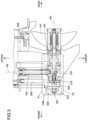
FIG. 3 is a partially enlarged cross-sectional view of the outboard motor ofEmbodiment 1, showing a partially enlarged cross-section cut at the position indicated by line III-III inFIG. 1 . -
FIG. 4 is an enlarged cross-sectional view of the part indicated by frame F1 inFIG. 3 . -
FIG. 5 is an enlarged cross-sectional view of the part indicated by frame F2 inFIG. 3 . -
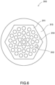
FIG. 6 is a front view of the inlet ofEmbodiment 1. -
FIG. 7 is a partially enlarged cross-sectional view of the outboard motor of Embodiment 2, showing the same area as inFIG. 5 enlarged. -
FIG. 8 is a front view of the inlet of Embodiment 2. -
FIG. 9 is a partially enlarged cross-sectional view of the outboard motor of Embodiment 3, showing the same area as inFIG. 5 enlarged. -
FIG. 10 is a front view of the inlet of Embodiment 3. - Specific examples of the technology disclosed by this specification are described below with reference to the drawings.
-
Embodiment 1 will be described with reference toFIGS. 1 to 4 . Aboat 1 ofEmbodiment 1 is equipped with ahull 10 and an outboard motor 100 (an example of the boat propulsion device), as shown inFIG. 1. FIG. 1 and other drawings described below show arrows representing each direction with respect to the position of theboat 1. More specifically, each figure shows arrows representing front (FRONT), rear (REAR), left (LEFT), right (RIGHT), upper (UPPER), and lower (LOWER) directions, respectively. The front-rear direction, left-right direction, and upper-lower direction (vertical direction) are orthogonal to each other. - The
hull 10 is a part of theboat 1 for occupants to ride. As shown inFIG. 1 , thehull 10 has ahull body 12 having aliving space 11, apilot seat 16 installed in theliving space 11, and anoperating device 17 installed near thepilot seat 16. Theoperating device 17 is a device for maneuvering the boat and includes, e.g., a steering wheel, a shift throttle lever, a joystick, a monitor, and an input device. Thehull 10 also has apartition wall 13 that partitions the rear end of theliving space 11 and atransom 14 positioned at the rear end of thehull 10. In the front-rear direction, there is aspace 15 between thetransom 14 and thepartition wall 13. - The
outboard motor 100 is a device that generates thrust to propel theboat 1. Theoutboard motor 100 in this embodiment is an electric outboard motor driven by an electric motor 120 (an example of a drive unit). Theoutboard motor 100 in the reference attitude will be described below unless otherwise specified. The reference attitude is the attitude of theoutboard motor 100 when theboat 1 is cruising (attitude shown inFIG. 1 ), in which the rotation axis Ad of the drive shaft 130 (described below) extends in the upper-lower direction and the rotation axis Apr of thepropeller shaft 140 extends in the front-rear direction. The front-rear direction, the left-right direction, and the upper-lower direction are defined based on theoutboard motor 100 in the reference attitude. - As shown in
FIG. 1 , theoutboard motor 100 is attached to thetransom 14 located at the rear (stern) of thehull 10. Theoutboard motor 100 has an outboard motormain body 110 and asuspension device 150. - As shown in
FIGS. 2 and3 , the outboard motormain body 110 includes acowl 114, acasing 116, anelectric motor 120, adrive shaft 130, apropeller 141, apropeller shaft 140, a coolingwater flow path 200, awater pump 210, afirst gear mechanism 180, asecond gear mechanism 190, and an inlet 310 (an example of the filter member). - As shown in
FIG. 2 , thecowl 114 is a housing located on top of the outboard motormain body 110. Thecasing 116 includes anupper case 116a and alower case 116b, as shown inFIG. 2 . Theupper case 116a is a housing located below thecowl 114. Thelower case 116b is a housing located below theupper case 116a. - The
lower case 116b has agear chamber 118 that stores oil therein and houses thefirst gear mechanism 180 and thesecond gear mechanism 190, as shown inFIG. 4 . - The
electric motor 120 is driven by electric power supplied from a battery (power source). Theelectric motor 120 includes a rotor including a permanent magnet, a stator including a coil to which the battery power is supplied, and a motor housing that houses the rotor and stator. Theelectric motor 120 is located inside thecowl 114. The battery may be located inside thecowl 114 or inside thehull 10. - The
drive shaft 130 is a rod-shaped member extending downward from theelectric motor 120 and housed within thecasing 116, as shown inFIG. 2 . Thedrive shaft 130 is arranged in an attitude in which its rotation axis Ad extends in the upper-lower direction. - As shown in
FIG. 4 , thedrive shaft 130 has a rod-shapedmain shaft 131 and anextension shaft 132 extending from the tip of themain shaft 131 opposite to the electric motor 120 (lower end inFIG. 4 ). Themain shaft 131 includes a constant-diameter shaft 131A extending from theelectric motor 120, which is a round rod of constant thickness, and a reduced-diameter shaft 131B connecting the constant-diameter shaft 131A and theextension shaft 132. Theextension shaft 132 extends coaxially with themain shaft 131 and has a round rod shape with a smaller diameter than the constant-diameter shaft 131A. The constant-diameter shaft 131A, the reduced-diameter shaft 131B, and theextension shaft 132 are arranged coaxially. - The
drive shaft 130 rotates around the rotation axis Ad by the rotational driving force of theelectric motor 120. Since theelectric motor 120 can rotate in both forward and reverse directions, thedrive shaft 130 can also rotate around the rotation axis line Ad in both forward direction (first rotation direction) to move theboat 1 forward and reverse direction (second rotation direction) to move theboat 1 backward, which is opposite to the forward direction, according to the rotational driving direction of theelectric motor 120. - The
propeller 141 is a rotating body having a plurality of blades. Thepropeller 141 generates thrust by rotation. - The
propeller shaft 140 is a rod-shaped member and extends in the front-rear direction inside thelower case 116b, as shown inFIGS. 2 ,3 , and4 . Thepropeller shaft 140 is rotatably supported by thelower case 116b via abearing 142. The rear end of thepropeller shaft 140 protrudes rearwardly from thelower case 116b, and thepropeller 141 is attached to this rear end. As thepropeller shaft 140 rotates around the rotation axis Apr, thepropeller 141 also rotates. - The cooling
water flow path 200 is located inside the outboard motormain body 110. The coolingwater flow path 200 is a channel through which cooling water (seawater, lake water, and river water, among others) taken from outside theoutboard motor 100 flows. The coolingwater flow path 200 has anintake port 201 that opens on the outer surface of thelower case 116b for taking cooling water into the interior and adrain port 202 that also opens on the outer surface of thelower case 116b for discharging cooling water to the exterior; the coolingwater flow path 200 extends from theintake port 201 through the periphery of theelectric motor 120 to thedrain port 202. Theintake port 201 is located below the waterline when theboat 1 is cruising, i.e., when theoutboard motor 100 is in the reference attitude. Theintake port 201 is open at the front end of thelower case 116b. - As shown in
FIG. 4 , a portion of the coolingwater flow path 200 is apump chamber 203. Thepump chamber 203 is located in front of thegear chamber 118 in thelower case 116b and is separated from thegear chamber 118 by apartition member 220. Thepartition member 220 has ashaft hole 221 that is connected to thepump chamber 203 and thegear chamber 118. - The
water pump 210 is a non-volumetric pump having animpeller 211 and apump shaft 212 that rotates together with theimpeller 211, as shown inFIG. 4 . In this embodiment, a centrifugal pump is exemplified as thewater pump 210. - The
impeller 211 is a rotating body having a plurality of blades and is located inside thepump chamber 203. Thepump shaft 212 is a rod-shaped member and extends in a front-rear direction. Thepump shaft 212 is inserted into theshaft hole 221 and is supported by thepartition member 220 in a rotatable manner via abearing 213. The rotation axis Apn of thepump shaft 212 coincides with the rotation axis Apr of thepropeller shaft 140. The front end of thepump shaft 212 is located inside thepump chamber 203, where theimpeller 211 is mounted. In other words, the water pump 210 (specifically, thepump shaft 212 and impeller 211) is located on the rotation axis Apr of thepropeller shaft 140. As thepump shaft 212 rotates around the rotation axis Apn, theimpeller 211 also rotates. The rear end of thepump shaft 212 is located inside thegear chamber 118. - Inside the
shaft hole 221, as shown inFIG. 4 , a plurality ofseal members 230 are arranged on the outer surface of thepump shaft 212 to fill the gap between the inner surface of theshaft hole 221 and thepump shaft 212. Eachseal member 230 is circular in shape, is composed of a material such as rubber having rubber elasticity, and encircles thepump shaft 212 all the way around. The plurality ofseal members 230 are arranged in line along the rotation axis Apn of thepump shaft 212. Theseseal members 230 prevent cooling water flowing into thepump chamber 203 from entering thegear chamber 118 through the gap between the inner circumferential surface of theshaft hole 221 and thepump shaft 212. - The portion of the cooling
water flow path 200 from theintake port 201 to thewater pump 210, i.e., the portion located between theintake port 201 and the pump chamber 203 (inlet channel 204), is located in front of thewater pump 210 and extends along the rotation axis Apn of thepump shaft 212, as shown inFIG. 4 . - As shown in
FIG. 5 , one portion of theinlet channel 204 adjacent to the intake port 201 (enlarged-diameter channel 205) has a larger inner diameter than the remaining portion adjacent to the pump chamber 203 (constant-diameter channel 206). On the inner surface of a member (e.g., a pipe) constituting theinlet channel 204, a first steppedsurface 207 is provided, which connects the inner surface of the enlarged-diameter channel 205 to the inner surface of the constant-diameter channel 206. The first steppedsurface 207 is arranged to face toward theintake port 201 and is perpendicular to the rotation axis Apn of thepump shaft 212. A threaded groove for fixing theinlet 310 is formed on the inner surface of the constant-diameter channel 206. - The
first gear mechanism 180 is a mechanism for transmitting the rotation of thedrive shaft 130 to thepropeller shaft 140, and thesecond gear mechanism 190 is a mechanism for transmitting the rotation of thedrive shaft 130 to thepump shaft 212. Thefirst gear mechanism 180 and thesecond gear mechanism 190 have different gear ratios. - The
first gear mechanism 180 has afirst gear 181 and asecond gear 182, as shown inFIG. 4 . Thefirst gear 181 is coaxially mounted to themain shaft 131 of the drive shaft 130 (more specifically, the reduced-diameter shaft 131B) and rotates together with thedrive shaft 130. Thesecond gear 182 is coaxially mounted to thepropeller shaft 140 and rotates together with thepropeller shaft 140. Thesecond gear 182 meshes with thefirst gear 181. Thefirst gear 181 and thesecond gear 182 are, e.g., bevel gears. - The
second gear mechanism 190 has athird gear 191 and afourth gear 192, as shown inFIG. 4 . Thethird gear 191 is a gear that is coaxially mounted to theextension shaft 132 of thedrive shaft 130 and rotates together with thedrive shaft 130. Thethird gear 191 has a smaller outer diameter than thefirst gear 181 and is located farther from theelectric motor 120 than thefirst gear 181. Thefourth gear 192 is coaxially mounted to thepump shaft 212 and rotates together with thepump shaft 212. Thefourth gear 192 meshes with thethird gear 191. Thethird gear 191 and thefourth gear 192 are, e.g., bevel gears. - The
first gear mechanism 180 and thesecond gear mechanism 190 are located inside thegear chamber 118. The four gears 181, 182, 191, and 192 are lubricated by oil provided inside thegear chamber 118. - The
inlet 310 is a member that is located inside theinlet channel 204 and prevents foreign objects contained in the cooling water taken from theintake port 201 from entering the coolingwater flow path 200 and has afilter plate 311 and a mountingcylinder 315, as shown inFIGS. 5 and6 . - The
filter plate 311 is disc-shaped and has a number of passage holes 312. The passage holes 312 are holes that penetrate from one side to the other and allow the passage of cooling water. The size of eachpassage hole 312 is sufficient to allow the cooling water to pass smoothly but to prevent the entering of foreign objects of a size that could clog the coolingwater flow path 200, such as algae or pebbles, e.g., a hole having an inner diameter of 2.5 mm. - The mounting
cylinder 315 is a cylindrical portion extending from one side of the filter plate 311 (right side ofFIG. 5 ) and has an outer diameter smaller than the outer diameter of thefilter plate 311. The outer surface of the mountingcylinder 315 has threads corresponding to the grooves threaded on the inner surface of the constant-diameter channel 206. - A circular attachment/
detachment ring 313 arranged along the outer circumferential edge protrudes from the other side of the filter plate 311 (left side ofFIG. 5 ). The recess defined by the attachment/detachment ring 313 andfilter plate 311 has a hexagonal inner circumferential edge and is an attachment/detachment recess 314 that fits a hexagonal wrench. - When the
inlet 310 is located within theinlet channel 204, thefilter plate 311 is disposed near theintake port 201 and perpendicular to the rotation axis Apn of thepump shaft 212 to separate the interior space of theinlet channel 204 from the exterior space. The outer circumferential edge of thefilter plate 311 abuts the first steppedsurface 207 to position theinlet 310. The mountingcylinder 315 is located on the rotation axis Apn of thepump shaft 212. Cooling water flows into thepump chamber 203 through thepassage hole 312 and the interior of the mountingcylinder 315. By turning theinlet 310 around the rotation axis Apn using a hexagonal wrench, theinlet 310 can be attached to or removed from the pipe constituting theinlet channel 204. - Since the
inlet 310 of this embodiment is made of resin, adhesion of theinlet 310 to the pipe constituting theinlet channel 204 due to corrosion can be suppressed compared to the case where theinlet 310 is made of metal. Examples of the material for theinlet 310 may include nylon and polyacetal. - The
suspension device 150 is a device for suspending the outboard motormain body 110 on thehull 10. Thesuspension device 150 includes a pair of left andright clamp brackets 152, atilt shaft 160, and aconnection bracket 156, as shown inFIG. 2 . - The pair of left and
right clamp brackets 152 are disposed behind thehull 10 in a state separated from each other in the left-right direction and are fixed to thetransom 14 of thehull 10 by using, e.g., bolts. Eachclamp bracket 152 has a cylindrical supportingportion 152a provided with a through-hole extending in the left-right directions. - The
tilt shaft 160 is a rod-shaped member. Thetilt shaft 160 is rotatably supported in the through-hole of the supportingportion 152a of theclamp bracket 152. The tilt axis At, which is the center line of thetilt shaft 160, constitutes an axis in the horizontal direction (left-right direction) in the tilting action of theoutboard motor 100. - The
connection bracket 156 is disposed so as to be sandwiched between the pair ofclamp brackets 152 and is supported by the supportingportion 152a of theclamp bracket 152 via thetilt shaft 160 in such a manner that theconnection bracket 156 can rotate around the tilt axis At. Theconnection bracket 156 is fixed to the outboard motormain body 110. Theconnection bracket 156 is rotationally driven around the tilt axis At with respect to theclamp bracket 152 by a tilt device (not shown) including an actuator such as, e.g., a hydraulic cylinder. - When the
connection bracket 156 rotates about the tilt axis At with respect to theclamp bracket 152, the outboard motormain body 110 fixed to theconnection bracket 156 also rotates about the tilt axis At. This achieves the tilting action of rotating the outboard motormain body 110 in the upper-lower direction with respect to thehull 10. By this tilting action, theoutboard motor 100 can change the angle around the tilt axis At of the outboard motormain body 110 in the range from the tilt-down state in which thepropeller 141 is located under the waterline (the state in which theoutboard motor 100 is in the reference attitude: the state shown inFIG. 1 ) to the tilt-up state in which thepropeller 141 is above the waterline. Trimming action to adjust the attitude of theboat 1 during cruising can also be performed by adjusting the angle around the tilt axis At of the outboard motormain body 110. - When the
boat 1 is cruising, theoutboard motor 100 is placed in the tilt-down state, and thelower case 116b and thepropeller 141 are positioned below the waterline. Theintake port 201,inlet channel 204,pump chamber 203, andwater pump 210 located inside thelower case 116b are also below the waterline, and cooling water flows into thepump chamber 203 from outside through theintake port 201 andinlet channel 204. At this time, theinlet 310, which is located in theinlet channel 204, prevents the entering of foreign objects of a size that could clog the coolingwater flow path 200, such as algae and pebbles. - When the
electric motor 120 is driven, thedrive shaft 130 rotates around the rotation axis Ad by the rotational driving force of theelectric motor 120. - The rotation of the
drive shaft 130 is transmitted to thepropeller shaft 140 via thefirst gear mechanism 180. When thefirst gear mechanism 180 transmits the forward rotation of thedrive shaft 130 to thepropeller shaft 140, thepropeller 141 rotating together with thepropeller shaft 140 generates thrust in the forward direction. When thefirst gear mechanism 180 transmits the reverse rotation of thedrive shaft 130 to thepropeller shaft 140, thepropeller 141 rotating together with thepropeller shaft 140 generates thrust in the rearward direction. - The rotation of the
drive shaft 130 is transmitted to thepump shaft 212 via thesecond gear mechanism 190, and theimpeller 211 rotates together with thepump shaft 212. Cooling water taken in from theintake port 201 is pumped through the coolingwater flow path 200 by centrifugal force generated by the rotation of theimpeller 211, and is supplied around theelectric motor 120 to cool theelectric motor 120. In addition to theelectric motor 120, the cooling water may also cool the battery, inverter, and reduction gears, among others, located inside the outboard motormain body 110. After being used for cooling, the cooling water is discharged to the outside through thedrain port 202. - The
intake port 201 and theinlet channel 204 are located on the rotation axis Apn of thepump shaft 212 and in front (bow side) of thewater pump 210, so that when theboat 1 moves forward, the cooling water flows through theintake port 201 and theinlet channel 204 from the front to theimpeller 211. This allows the cooling water to be pumped efficiently, especially when theboat 1 is moving forward. In this configuration, there is concern that foreign objects contained in the cooling water may also flow in with great force and collide with theimpeller 211. To suppress this, theinlet 310 is arranged in theinlet channel 204 in this configuration. Theinlet 310 prevents foreign objects from entering the coolingwater flow path 200 and suppresses damage to theimpeller 211. - As the
drive shaft 130 rotates in both the forward and reverse directions, thepump shaft 212 also rotates around the rotation axis Apn in both the direction of rotation associated with the forward direction of thedrive shaft 130 and the direction of rotation associated with the reverse direction of thedrive shaft 130; thewater pump 210, which is a non-volumetric pump with no restriction on the direction of rotation, operates normally no matter which direction thedrive shaft 130 rotates. - As described above, the
outboard motor 100 of this embodiment is anoutboard motor 100 to be mounted on thehull 10 and includes a coolingwater flow path 200 having anintake port 201 for taking in cooling water from the outside and through which cooling water flows; and awater pump 210 including animpeller 211 and apump shaft 212 rotating together with theimpeller 211 to pump the cooling water into the coolingwater flow path 200, wherein theinlet channel 204 of the coolingwater flow path 200 from theintake port 201 to thewater pump 210 is located in front of thewater pump 210 and extends along the rotation axis Apn of thepump shaft 212, and theinlet 310 that allows the passage of the cooling water and inhibits entry of foreign objects is placed inside theinlet channel 204. - According to the above configuration, the cooling water taken from outside flows from the front to the
impeller 211 attached to thepump shaft 212 so that the cooling water can be pumped efficiently. This configuration also suppresses damage to thewater pump 210 caused by foreign objects colliding with thewater pump 210. - The
outboard motor 100 further includes theelectric motor 120, thedrive shaft 130 rotationally driven by theelectric motor 120, thepropeller 141, and thepropeller shaft 140 rotating together with thepropeller 141. Thedrive shaft 130 is capable of rotating in both the forward direction and the reverse direction, which is opposite to the forward direction, and thewater pump 210 is a non-volumetric pump. - According to this configuration, the
drive shaft 130, which can rotate in both forward and reverse directions, eliminates the need for a clutch mechanism such as a dog clutch, thereby providing a relatively large space around thepropeller shaft 140. This space can be used to accommodate thewater pump 210, avoiding increasing the size of theoutboard motor 100 and optimizing the arrangement of the components necessary to transport cooling water. In addition, since thenon-volumetric water pump 210 has no restrictions on the direction of rotation, it is suitable as a pump, the rotation of which is transmitted from thedrive shaft 130 that can rotate in both forward and reverse directions. - In addition, the
water pump 210 is located on the rotation axis Apr of thepropeller shaft 140. - This configuration allows the
water pump 210 to be positioned without protruding sideways from the rotation axis Apr of thepropeller shaft 140, thereby avoiding a reduction in the propulsive force of thehull 10. - In addition, since the
inlet 310 is made of resin, compared to the case where theinlet 310 is made of metal, adhesion of theinlet 310 to the member constituting theinlet channel 204 due to corrosion can be suppressed. - Embodiment 2 will now be explained with reference to
FIGS. 7 and8 . In this embodiment, the material and shape of the inlet 320 (an example of the filter member) are different from those ofEmbodiment 1. In this embodiment, the same configuration as inEmbodiment 1 will be marked with the same symbol, and the explanation will be omitted. - The
inlet 320 is a member that is located inside theinlet channel 204 and prevents foreign objects contained in the cooling water taken fromintake port 201 from entering the coolingwater flow path 200, as inEmbodiment 1. Theinlet 320 has afilter plate 321 and a mountingcylinder 315. - The
filter plate 321 is disc-shaped with an outer diameter larger than that of the mountingcylinder 315 and has a number of passage holes 322. The passage holes 322 are holes that penetrate from one side of thefilter plate 321 to the other side and allow the passage of cooling water. At the center position of thefilter plate 311, there is an attachment/detachment hole 323 with a hexagonal inner circumferential edge that fits a hexagonal wrench. As inEmbodiment 1, the mountingcylinder 315 is a cylindrical portion extending from one side of the filter plate 311 (right side inFIG. 7 ) and having threads formed on the outer surface. - When the
inlet 320 is attached to the inside of theinlet channel 204, as inEmbodiment 1, thefilter plate 321 is disposed near theintake port 201 and perpendicular to the rotation axis Apn of thepump shaft 212 to separate the interior space of theinlet channel 204 from the exterior space. The outer circumferential edge of thefilter plate 321 abuts the first steppedsurface 207 to position theinlet 320. The cooling water can flow into the interior of thepump chamber 203 through thepassage hole 322 and the mountingcylinder 315. The mountingcylinder 315 is located on the rotation axis Apn of thepump shaft 212. By turning theinlet 320 around the rotation axis Apn using a hexagonal wrench, theinlet 320 can be attached to or removed from the pipe constituting theinlet channel 204. - Since the
inlet 320 of this embodiment is made of glass fiber reinforced plastic, adhesion of theinlet 320 to the pipe constituting theinlet channel 204 due to corrosion can be suppressed compared to the case where theinlet 320 is made of metal. In addition, since the glass fiber reinforced plastic is stronger than resin that does not contain glass fibers, theinlet 320 can be suppressed from being damaged by collisions with foreign objects while cruising, collisions with a shore while anchoring, and the like. - Next, Embodiment 3 will be described with reference to
FIGS. 9 and10 . This embodiment differs fromEmbodiment 1 in that inlet 330 (an example of the filter member) is composed of two members, afilter body 340 and a holdingmember 350. In this embodiment, the same configuration as inEmbodiment 1 will be marked with the same symbol, and the explanation will be omitted. - The
inlet 330 is a member that is located inside theinlet channel 204 and prevents foreign objects contained in the cooling water taken fromintake port 201 from entering the coolingwater flow path 200, as inEmbodiment 1. Theinlet 330 has afilter body 340 and a holdingmember 350 that holds thefilter body 340 and is fixed to the interior of theinlet channel 204. - The
filter body 340 is a metal plate having a hexagonal outline and a curved shape that matches the curved shape of the front end surface of thelower case 116b. Thefilter body 340 has a number of passage holes 341. The passage holes 341 are holes that penetrate thefilter body 340 from one surface to the other surface and allow the passage of cooling water. Two parallel sides of the six sides constituting the outer circumference of thefilter body 340 respectively have a lockingprojection 343 projecting therefrom. On the inner surface of onepassage hole 341A located at the center of thefilter body 340, two attachment/detachment grooves 342 are provided, which are recessed outwardly. The two attachment/detachment grooves 342 are arranged to face each other. - The holding
member 350 is made of resin, is cylindrical in shape as a whole, and has throughholes 351 open at both ends. At one end of the holdingmember 350, an outwardlyprotruding flange 352 is provided. The outer surface of the holdingmember 350 has threads corresponding to the grooves threaded on the inner surface of the constant-diameter channel 206, except for the portion where theflange 352 is provided. - A portion of the through
hole 351 on theflange 352 side has a hexagonal inner circumferential edge and is afilter receiving hole 351A for receiving thefilter body 340. Two parallel sides of the six sides constituting the inner circumferential edge of thefilter receiving hole 351A are respectively provided with a lockinggroove 353 which is recessed outwardly to receive the lockingprojection 343. - When the
inlet 330 is attached to the inside of theinlet channel 204, the holdingmember 350 is disposed on the rotation axis Apn of thepump shaft 212. Thefilter body 340 is disposed near theintake port 201 and perpendicular to the rotation axis Apn of thepump shaft 212 to separate the interior space of theinlet channel 204 from the exterior space. Theflange 352 abuts the first steppedsurface 207 to position theinlet 330. The cooling water can flow into the interior of thepump chamber 203 through the passage holes 341 and the throughhole 351. - The
inlet 330 is attached to the interior of theinlet channel 204 by first inserting a hexagonal wrench into thefilter receiving hole 351A to rotate the holdingmember 350 around the rotation axis Apn, thereby screwing the holdingmember 350 to the pipe constituting theinlet channel 204. Next, thefilter body 340 is fitted into the interior of thefilter receiving hole 351A. Thefilter body 340 is secured to the interior of thefilter receiving hole 351A by the lockingprojection 343 inserted into the lockinggroove 353. - The
inlet 330 is detached from theinlet channel 204 by first inserting a removal jig into the interior of the attachment/detachment groove 342, hooking the jig onto thefilter body 340 and then pulling the jig to pull thefilter body 340 out of thefilter receiving hole 351A. Next, the holdingmember 350 is removed from the pipe constituting theinlet channel 204 by inserting a hexagonal wrench inside thefilter receiving hole 351A and rotating the holdingmember 350 around the rotation axis Apn. - Since the holding
member 350 of theinlet 330 that contacts the pipe constituting theinlet channel 204 is made of resin, adhesion of the holdingmember 350 to the pipe due to corrosion can be suppressed compared to the case where the holdingmember 350 is made of metal. Examples of the material for the holdingmember 350 may include nylon and polyacetal. In addition, since thefilter body 340 is made of metal, thefilter body 340 can be made stronger compared to the case where the whole of the inlet is made of resin, and thus thefilter body 340 can be suppressed from being damaged by collisions with foreign objects while cruising, collisions with a shore while anchoring, and the like. The material of thefilter body 340 is preferably a metal that is resistant to corrosion, e.g., aluminum, which forms an oxide film on its surface, is suitable. - (1) In the above embodiment, as an example, the electric
outboard motor 100 is driven by theelectric motor 120, but the drive unit of the outboard motor does not have to be an electric motor and may be, e.g., an internal combustion engine. - (2) In the above embodiment, the
drive shaft 130 is rotatable in both forward and reverse directions according to the rotational drive direction of theelectric motor 120, but the outboard motor may include an internal combustion engine as a drive unit and a shift mechanism for switching the rotational direction of the drive shaft. - (3) In the above embodiment, circular holes are illustrated as the passage holes 312, 322, and 341, but the shape of the passage holes is freely selectable, e.g., the shape may be polygonal.
- (4) In the above embodiment, the
inlets inlet channel 204, but the method of mounting the filter member inside the inlet channel is freely selectable and may be, e.g., by a bolt and nut. - (5) In the above embodiment, the
inlets
Claims (13)
- A boat propulsion device configured to be provided on a hull (10), the boat propulsion device comprising:a cooling water flow path (200) having an intake port (201) for taking in cooling water from the outside and configured for cooling water to flow through; anda water pump (210) including an impeller (211) and a pump shaft (212) configured to rotate around a rotation axis (Apn) together with the impeller (211) to pump the cooling water into the cooling water flow path (200), whereina filter member (310, 320, 330) that allows the passage of the cooling water and is configured to inhibit entry of foreign objects is placed at the intake port (201), andthe filter member (310, 320, 330) is placed on a rotation axis (Apn) of the pump shaft (212).
- The boat propulsion device according to claim 1, wherein an inlet channel (204) of the cooling water flow path (200) from the intake port (201) to the water pump (210) extends along the rotation axis (Apn) of the pump shaft (212), and
the filter member (310, 320, 330) is placed inside the inlet channel (204). - The boat propulsion device according to claim 1 or 2, further comprisinga propeller (141); anda propeller shaft (140) configured to rotate together with the propeller (141), wherein the water pump (210) is arranged between the intake port (201) and the propeller (141) with regard to the rotation axis (Apn) of the pump shaft (212).
- The boat propulsion device according to claim 3, further comprising,a drive unit (120);a drive shaft (130) configured to be rotationally driven by the drive unit (120), wherein the drive shaft (130) is rotatable in both a first rotation direction and a second rotation direction, which is opposite to the first rotation direction, andthe water pump (210) is a non-volumetric pump.
- The boat propulsion device according to claim 4, wherein the drive unit is an electric motor (120) configured to be driven by electric power supplied from a power source.
- The boat propulsion device according to claim 4 or 5, wherein the water pump (210) is located on a rotation axis (Apr) of the propeller shaft (140).
- The boat propulsion device according to any one of claims 1 to 6, wherein the water pump (210) is a centrifugal pump.
- The boat propulsion device according to any one of claims 1 to 7, wherein the filter member (310) is made of resin.
- The boat propulsion device according to any one of claims 1 to 7, wherein the filter member (320) is made of glass fiber reinforced plastic.
- The boat propulsion device according to any one of claims 1 to 7, wherein the filter member (330) comprises:a holding member (350) having a through hole (351) and fixed inside the inlet channel (204); anda filter body (340) held inside the through hole (351) that allows the passage of the cooling water and is configured to inhibit entry of foreign objects, whereinthe holding member (350) is made of resin, andthe filter body (340) is made of metal.
- An outboard motor (100) configured to be mounted on a transom (14) positioned at a rear end of the hull (10), wherein the outboard motor (100) comprises a boat propulsion device according to any one of claims 1 to 10.
-
- A boat (1) having a hull (10) and an outboard motor (100) according to claim 11 attached to the transom (14) positioned at the rear end of the hull (10).
Applications Claiming Priority (1)
| Application Number | Priority Date | Filing Date | Title |
|---|---|---|---|
| JP2022206223A JP2024090362A (en) | 2022-12-23 | 2022-12-23 | Outboard motors and marine propulsion units |
Publications (3)
| Publication Number | Publication Date |
|---|---|
| EP4390078A2 true EP4390078A2 (en) | 2024-06-26 |
| EP4390078A3 EP4390078A3 (en) | 2024-08-28 |
| EP4390078B1 EP4390078B1 (en) | 2026-02-11 |
Family
ID=88372287
Family Applications (1)
| Application Number | Title | Priority Date | Filing Date |
|---|---|---|---|
| EP23202931.4A Active EP4390078B1 (en) | 2022-12-23 | 2023-10-11 | Boat propulsion device and outboard motor |
Country Status (3)
| Country | Link |
|---|---|
| US (1) | US20240208629A1 (en) |
| EP (1) | EP4390078B1 (en) |
| JP (1) | JP2024090362A (en) |
Families Citing this family (2)
| Publication number | Priority date | Publication date | Assignee | Title |
|---|---|---|---|---|
| KR102539358B1 (en) * | 2023-02-22 | 2023-06-02 | 주식회사 아이윈 | Impeller driving device for cooling pump of electric outboard |
| US20250333152A1 (en) * | 2024-04-30 | 2025-10-30 | Vision Marine Technologies | Controlling a cooling system water intake pump of an electric marine vessel |
Citations (1)
| Publication number | Priority date | Publication date | Assignee | Title |
|---|---|---|---|---|
| JP2015145137A (en) | 2014-01-31 | 2015-08-13 | 本田技研工業株式会社 | Outboard motor |
Family Cites Families (13)
| Publication number | Priority date | Publication date | Assignee | Title |
|---|---|---|---|---|
| US2153626A (en) * | 1937-05-10 | 1939-04-11 | B M Kissel | Outboard motor |
| US3025824A (en) * | 1959-10-28 | 1962-03-20 | Mcculloch Corp | Outboard motor water pump arrangement |
| US3367116A (en) * | 1965-12-13 | 1968-02-06 | Richard C. Stallman | Intake grill for water jet pump |
| US4832635A (en) * | 1988-02-26 | 1989-05-23 | Brunswick Corporation | Nose construction for the gear case of a marine drive |
| JP3537547B2 (en) * | 1995-06-23 | 2004-06-14 | ヤマハマリン株式会社 | Cooling water passage structure for ship propulsion |
| US6146223A (en) * | 1999-04-19 | 2000-11-14 | Brunswick Corporation | Marine propulsion unit with water inlets in all quadrants of the front portion of its torpedo-shape gearcase |
| US8333629B2 (en) * | 2008-10-30 | 2012-12-18 | Brp Us Inc. | System and method for cooling a marine outboard engine |
| US9145193B2 (en) * | 2011-11-22 | 2015-09-29 | Suzuki Motor Corporation | Cooling water passage structure of outboard motor |
| JP2017206184A (en) * | 2016-05-20 | 2017-11-24 | スズキ株式会社 | Outboard motor |
| WO2020129133A1 (en) * | 2018-12-17 | 2020-06-25 | 本田技研工業株式会社 | Outboard motor |
| JP7293800B2 (en) * | 2019-03-28 | 2023-06-20 | スズキ株式会社 | Cooling device for power source for ship propulsion device |
| JP2021030930A (en) * | 2019-08-27 | 2021-03-01 | ヤマハ発動機株式会社 | Outboard motor and vessel |
| JP2022117651A (en) * | 2021-02-01 | 2022-08-12 | 本田技研工業株式会社 | Outboard engine |
-
2022
- 2022-12-23 JP JP2022206223A patent/JP2024090362A/en active Pending
-
2023
- 2023-10-11 EP EP23202931.4A patent/EP4390078B1/en active Active
- 2023-10-24 US US18/383,047 patent/US20240208629A1/en active Pending
Patent Citations (1)
| Publication number | Priority date | Publication date | Assignee | Title |
|---|---|---|---|---|
| JP2015145137A (en) | 2014-01-31 | 2015-08-13 | 本田技研工業株式会社 | Outboard motor |
Also Published As
| Publication number | Publication date |
|---|---|
| JP2024090362A (en) | 2024-07-04 |
| US20240208629A1 (en) | 2024-06-27 |
| EP4390078A3 (en) | 2024-08-28 |
| EP4390078B1 (en) | 2026-02-11 |
Similar Documents
| Publication | Publication Date | Title |
|---|---|---|
| EP4390078B1 (en) | Boat propulsion device and outboard motor | |
| US7387556B1 (en) | Exhaust system for a marine propulsion device having a driveshaft extending vertically through a bottom portion of a boat hull | |
| JP2023044489A (en) | Hybrid ship propulsion machine | |
| JP3638576B2 (en) | Marine side thruster | |
| US6468119B1 (en) | Composite stern drive assembly | |
| US20230242231A1 (en) | Integrated Propulsion and Steering System | |
| EP2077228A2 (en) | Outboard motor | |
| EP1792826B1 (en) | Means for bearing a propulsion unit and a propulsion system for a waterborne vessel | |
| US6468120B1 (en) | Single cylinder trim/tilt assembly | |
| US11333058B2 (en) | Marine outboard motor with drive shaft and cooling system | |
| KR20060121175A (en) | Outboard Jet Drive Ship Propulsion Systems | |
| EP4390077B1 (en) | Outboard motor | |
| US6971932B2 (en) | Marine inboard/outboard system | |
| US5376027A (en) | Marine propulsion mechanism for water craft | |
| JP2023044488A (en) | Hybrid ship propulsion machine | |
| US10106236B2 (en) | Outboard motor | |
| US20170334537A1 (en) | Outboard motor | |
| US20240208628A1 (en) | Outboard motor | |
| US7927160B1 (en) | Variable pitch propeller | |
| EP1731418B1 (en) | Propulsion unit for motor boats | |
| US5018999A (en) | Propeller driving device of marine propulsion unit | |
| KR101596694B1 (en) | Outboard moter | |
| EP0811550A2 (en) | Drive means and a boat having drive means | |
| JPH05270489A (en) | Outboard motor | |
| CA3225584A1 (en) | Thruster system for a watercraft |
Legal Events
| Date | Code | Title | Description |
|---|---|---|---|
| PUAI | Public reference made under article 153(3) epc to a published international application that has entered the european phase |
Free format text: ORIGINAL CODE: 0009012 |
|
| STAA | Information on the status of an ep patent application or granted ep patent |
Free format text: STATUS: THE APPLICATION HAS BEEN PUBLISHED |
|
| AK | Designated contracting states |
Kind code of ref document: A2 Designated state(s): AL AT BE BG CH CY CZ DE DK EE ES FI FR GB GR HR HU IE IS IT LI LT LU LV MC ME MK MT NL NO PL PT RO RS SE SI SK SM TR |
|
| PUAL | Search report despatched |
Free format text: ORIGINAL CODE: 0009013 |
|
| AK | Designated contracting states |
Kind code of ref document: A3 Designated state(s): AL AT BE BG CH CY CZ DE DK EE ES FI FR GB GR HR HU IE IS IT LI LT LU LV MC ME MK MT NL NO PL PT RO RS SE SI SK SM TR |
|
| RIC1 | Information provided on ipc code assigned before grant |
Ipc: F01P 11/06 20060101ALN20240719BHEP Ipc: B63H 1/00 20060101ALI20240719BHEP Ipc: F01P 5/10 20060101ALI20240719BHEP Ipc: F01P 3/20 20060101AFI20240719BHEP |
|
| P01 | Opt-out of the competence of the unified patent court (upc) registered |
Free format text: CASE NUMBER: APP_64545/2024 Effective date: 20241205 |
|
| STAA | Information on the status of an ep patent application or granted ep patent |
Free format text: STATUS: REQUEST FOR EXAMINATION WAS MADE |
|
| 17P | Request for examination filed |
Effective date: 20250217 |
|
| GRAP | Despatch of communication of intention to grant a patent |
Free format text: ORIGINAL CODE: EPIDOSNIGR1 |
|
| STAA | Information on the status of an ep patent application or granted ep patent |
Free format text: STATUS: GRANT OF PATENT IS INTENDED |
|
| RIC1 | Information provided on ipc code assigned before grant |
Ipc: F01P 3/20 20060101AFI20250909BHEP Ipc: F01P 5/10 20060101ALI20250909BHEP Ipc: B63H 1/00 20060101ALI20250909BHEP Ipc: B63H 20/28 20060101ALI20250909BHEP Ipc: F01P 11/06 20060101ALN20250909BHEP |
|
| INTG | Intention to grant announced |
Effective date: 20250925 |
|
| GRAS | Grant fee paid |
Free format text: ORIGINAL CODE: EPIDOSNIGR3 |
|
| GRAA | (expected) grant |
Free format text: ORIGINAL CODE: 0009210 |
|
| STAA | Information on the status of an ep patent application or granted ep patent |
Free format text: STATUS: THE PATENT HAS BEEN GRANTED |
|
| AK | Designated contracting states |
Kind code of ref document: B1 Designated state(s): AL AT BE BG CH CY CZ DE DK EE ES FI FR GB GR HR HU IE IS IT LI LT LU LV MC ME MK MT NL NO PL PT RO RS SE SI SK SM TR |
|
| REG | Reference to a national code |
Ref country code: CH Ref legal event code: F10 Free format text: ST27 STATUS EVENT CODE: U-0-0-F10-F00 (AS PROVIDED BY THE NATIONAL OFFICE) Effective date: 20260211 Ref country code: GB Ref legal event code: FG4D |
|
| REG | Reference to a national code |
Ref country code: DE Ref legal event code: R096 Ref document number: 602023011830 Country of ref document: DE |
|
| REG | Reference to a national code |
Ref country code: IE Ref legal event code: FG4D |
|
| REG | Reference to a national code |
Ref country code: NL Ref legal event code: FP |
|
| PG25 | Lapsed in a contracting state [announced via postgrant information from national office to epo] |
Ref country code: RS Free format text: LAPSE BECAUSE OF FAILURE TO SUBMIT A TRANSLATION OF THE DESCRIPTION OR TO PAY THE FEE WITHIN THE PRESCRIBED TIME-LIMIT Effective date: 20260511 |
|
| PG25 | Lapsed in a contracting state [announced via postgrant information from national office to epo] |
Ref country code: ES Free format text: LAPSE BECAUSE OF FAILURE TO SUBMIT A TRANSLATION OF THE DESCRIPTION OR TO PAY THE FEE WITHIN THE PRESCRIBED TIME-LIMIT Effective date: 20260211 |
|
| PG25 | Lapsed in a contracting state [announced via postgrant information from national office to epo] |
Ref country code: PL Free format text: LAPSE BECAUSE OF FAILURE TO SUBMIT A TRANSLATION OF THE DESCRIPTION OR TO PAY THE FEE WITHIN THE PRESCRIBED TIME-LIMIT Effective date: 20260211 |
|
| PG25 | Lapsed in a contracting state [announced via postgrant information from national office to epo] |
Ref country code: GR Free format text: LAPSE BECAUSE OF FAILURE TO SUBMIT A TRANSLATION OF THE DESCRIPTION OR TO PAY THE FEE WITHIN THE PRESCRIBED TIME-LIMIT Effective date: 20260512 |
|
| REG | Reference to a national code |
Ref country code: LT Ref legal event code: MG9D |
|
| PG25 | Lapsed in a contracting state [announced via postgrant information from national office to epo] |
Ref country code: LT Free format text: LAPSE BECAUSE OF FAILURE TO SUBMIT A TRANSLATION OF THE DESCRIPTION OR TO PAY THE FEE WITHIN THE PRESCRIBED TIME-LIMIT Effective date: 20260211 |
|
| PG25 | Lapsed in a contracting state [announced via postgrant information from national office to epo] |
Ref country code: NO Free format text: LAPSE BECAUSE OF FAILURE TO SUBMIT A TRANSLATION OF THE DESCRIPTION OR TO PAY THE FEE WITHIN THE PRESCRIBED TIME-LIMIT Effective date: 20260511 |
|
| PG25 | Lapsed in a contracting state [announced via postgrant information from national office to epo] |
Ref country code: FI Free format text: LAPSE BECAUSE OF FAILURE TO SUBMIT A TRANSLATION OF THE DESCRIPTION OR TO PAY THE FEE WITHIN THE PRESCRIBED TIME-LIMIT Effective date: 20260211 Ref country code: AT Free format text: LAPSE BECAUSE OF FAILURE TO SUBMIT A TRANSLATION OF THE DESCRIPTION OR TO PAY THE FEE WITHIN THE PRESCRIBED TIME-LIMIT Effective date: 20260211 Ref country code: SE Free format text: LAPSE BECAUSE OF FAILURE TO SUBMIT A TRANSLATION OF THE DESCRIPTION OR TO PAY THE FEE WITHIN THE PRESCRIBED TIME-LIMIT Effective date: 20260211 |
|
| REG | Reference to a national code |
Ref country code: AT Ref legal event code: MK05 Ref document number: 1885800 Country of ref document: AT Kind code of ref document: T Effective date: 20260211 |
|
| PG25 | Lapsed in a contracting state [announced via postgrant information from national office to epo] |
Ref country code: HR Free format text: LAPSE BECAUSE OF FAILURE TO SUBMIT A TRANSLATION OF THE DESCRIPTION OR TO PAY THE FEE WITHIN THE PRESCRIBED TIME-LIMIT Effective date: 20260211 |
|
| PG25 | Lapsed in a contracting state [announced via postgrant information from national office to epo] |
Ref country code: PT Free format text: LAPSE BECAUSE OF FAILURE TO SUBMIT A TRANSLATION OF THE DESCRIPTION OR TO PAY THE FEE WITHIN THE PRESCRIBED TIME-LIMIT Effective date: 20260611 Ref country code: IS Free format text: LAPSE BECAUSE OF FAILURE TO SUBMIT A TRANSLATION OF THE DESCRIPTION OR TO PAY THE FEE WITHIN THE PRESCRIBED TIME-LIMIT Effective date: 20260611 |
|
| PG25 | Lapsed in a contracting state [announced via postgrant information from national office to epo] |
Ref country code: LV Free format text: LAPSE BECAUSE OF FAILURE TO SUBMIT A TRANSLATION OF THE DESCRIPTION OR TO PAY THE FEE WITHIN THE PRESCRIBED TIME-LIMIT Effective date: 20260211 |
|
| PG25 | Lapsed in a contracting state [announced via postgrant information from national office to epo] |
Ref country code: BG Free format text: LAPSE BECAUSE OF FAILURE TO SUBMIT A TRANSLATION OF THE DESCRIPTION OR TO PAY THE FEE WITHIN THE PRESCRIBED TIME-LIMIT Effective date: 20260211 |