EP4390060A1 - Blade outer air seal with angle-oriented ply layup for cmc compound radii - Google Patents
Blade outer air seal with angle-oriented ply layup for cmc compound radii Download PDFInfo
- Publication number
- EP4390060A1 EP4390060A1 EP23218234.5A EP23218234A EP4390060A1 EP 4390060 A1 EP4390060 A1 EP 4390060A1 EP 23218234 A EP23218234 A EP 23218234A EP 4390060 A1 EP4390060 A1 EP 4390060A1
- Authority
- EP
- European Patent Office
- Prior art keywords
- fiber plies
- gas turbine
- turbine engine
- ceramic matrix
- recited
- Prior art date
- Legal status (The legal status is an assumption and is not a legal conclusion. Google has not performed a legal analysis and makes no representation as to the accuracy of the status listed.)
- Pending
Links
Images

Classifications
-
- F—MECHANICAL ENGINEERING; LIGHTING; HEATING; WEAPONS; BLASTING
- F01—MACHINES OR ENGINES IN GENERAL; ENGINE PLANTS IN GENERAL; STEAM ENGINES
- F01D—NON-POSITIVE DISPLACEMENT MACHINES OR ENGINES, e.g. STEAM TURBINES
- F01D9/00—Stators
- F01D9/02—Nozzles; Nozzle boxes; Stator blades; Guide conduits, e.g. individual nozzles
- F01D9/04—Nozzles; Nozzle boxes; Stator blades; Guide conduits, e.g. individual nozzles forming ring or sector
-
- F—MECHANICAL ENGINEERING; LIGHTING; HEATING; WEAPONS; BLASTING
- F01—MACHINES OR ENGINES IN GENERAL; ENGINE PLANTS IN GENERAL; STEAM ENGINES
- F01D—NON-POSITIVE DISPLACEMENT MACHINES OR ENGINES, e.g. STEAM TURBINES
- F01D11/00—Preventing or minimising internal leakage of working-fluid, e.g. between stages
- F01D11/08—Preventing or minimising internal leakage of working-fluid, e.g. between stages for sealing space between rotor blade tips and stator
-
- F—MECHANICAL ENGINEERING; LIGHTING; HEATING; WEAPONS; BLASTING
- F01—MACHINES OR ENGINES IN GENERAL; ENGINE PLANTS IN GENERAL; STEAM ENGINES
- F01D—NON-POSITIVE DISPLACEMENT MACHINES OR ENGINES, e.g. STEAM TURBINES
- F01D25/00—Component parts, details, or accessories, not provided for in, or of interest apart from, other groups
- F01D25/005—Selecting particular materials
-
- F—MECHANICAL ENGINEERING; LIGHTING; HEATING; WEAPONS; BLASTING
- F01—MACHINES OR ENGINES IN GENERAL; ENGINE PLANTS IN GENERAL; STEAM ENGINES
- F01D—NON-POSITIVE DISPLACEMENT MACHINES OR ENGINES, e.g. STEAM TURBINES
- F01D25/00—Component parts, details, or accessories, not provided for in, or of interest apart from, other groups
- F01D25/24—Casings; Casing parts, e.g. diaphragms, casing fastenings
-
- F—MECHANICAL ENGINEERING; LIGHTING; HEATING; WEAPONS; BLASTING
- F16—ENGINEERING ELEMENTS AND UNITS; GENERAL MEASURES FOR PRODUCING AND MAINTAINING EFFECTIVE FUNCTIONING OF MACHINES OR INSTALLATIONS; THERMAL INSULATION IN GENERAL
- F16J—PISTONS; CYLINDERS; SEALINGS
- F16J15/00—Sealings
- F16J15/02—Sealings between relatively-stationary surfaces
- F16J15/06—Sealings between relatively-stationary surfaces with solid packing compressed between sealing surfaces
- F16J15/10—Sealings between relatively-stationary surfaces with solid packing compressed between sealing surfaces with non-metallic packing
- F16J15/104—Sealings between relatively-stationary surfaces with solid packing compressed between sealing surfaces with non-metallic packing characterised by structure
-
- F—MECHANICAL ENGINEERING; LIGHTING; HEATING; WEAPONS; BLASTING
- F01—MACHINES OR ENGINES IN GENERAL; ENGINE PLANTS IN GENERAL; STEAM ENGINES
- F01D—NON-POSITIVE DISPLACEMENT MACHINES OR ENGINES, e.g. STEAM TURBINES
- F01D5/00—Blades; Blade-carrying members; Heating, heat-insulating, cooling or antivibration means on the blades or the members
- F01D5/12—Blades
- F01D5/28—Selecting particular materials; Particular measures relating thereto; Measures against erosion or corrosion
- F01D5/282—Selecting composite materials, e.g. blades with reinforcing filaments
-
- F—MECHANICAL ENGINEERING; LIGHTING; HEATING; WEAPONS; BLASTING
- F05—INDEXING SCHEMES RELATING TO ENGINES OR PUMPS IN VARIOUS SUBCLASSES OF CLASSES F01-F04
- F05D—INDEXING SCHEME FOR ASPECTS RELATING TO NON-POSITIVE-DISPLACEMENT MACHINES OR ENGINES, GAS-TURBINES OR JET-PROPULSION PLANTS
- F05D2220/00—Application
- F05D2220/30—Application in turbines
- F05D2220/32—Application in turbines in gas turbines
-
- F—MECHANICAL ENGINEERING; LIGHTING; HEATING; WEAPONS; BLASTING
- F05—INDEXING SCHEMES RELATING TO ENGINES OR PUMPS IN VARIOUS SUBCLASSES OF CLASSES F01-F04
- F05D—INDEXING SCHEME FOR ASPECTS RELATING TO NON-POSITIVE-DISPLACEMENT MACHINES OR ENGINES, GAS-TURBINES OR JET-PROPULSION PLANTS
- F05D2240/00—Components
- F05D2240/10—Stators
- F05D2240/11—Shroud seal segments
-
- F—MECHANICAL ENGINEERING; LIGHTING; HEATING; WEAPONS; BLASTING
- F05—INDEXING SCHEMES RELATING TO ENGINES OR PUMPS IN VARIOUS SUBCLASSES OF CLASSES F01-F04
- F05D—INDEXING SCHEME FOR ASPECTS RELATING TO NON-POSITIVE-DISPLACEMENT MACHINES OR ENGINES, GAS-TURBINES OR JET-PROPULSION PLANTS
- F05D2240/00—Components
- F05D2240/55—Seals
-
- F—MECHANICAL ENGINEERING; LIGHTING; HEATING; WEAPONS; BLASTING
- F05—INDEXING SCHEMES RELATING TO ENGINES OR PUMPS IN VARIOUS SUBCLASSES OF CLASSES F01-F04
- F05D—INDEXING SCHEME FOR ASPECTS RELATING TO NON-POSITIVE-DISPLACEMENT MACHINES OR ENGINES, GAS-TURBINES OR JET-PROPULSION PLANTS
- F05D2250/00—Geometry
- F05D2250/70—Shape
- F05D2250/75—Shape given by its similarity to a letter, e.g. T-shaped
-
- F—MECHANICAL ENGINEERING; LIGHTING; HEATING; WEAPONS; BLASTING
- F05—INDEXING SCHEMES RELATING TO ENGINES OR PUMPS IN VARIOUS SUBCLASSES OF CLASSES F01-F04
- F05D—INDEXING SCHEME FOR ASPECTS RELATING TO NON-POSITIVE-DISPLACEMENT MACHINES OR ENGINES, GAS-TURBINES OR JET-PROPULSION PLANTS
- F05D2300/00—Materials; Properties thereof
- F05D2300/60—Properties or characteristics given to material by treatment or manufacturing
- F05D2300/601—Fabrics
-
- F—MECHANICAL ENGINEERING; LIGHTING; HEATING; WEAPONS; BLASTING
- F05—INDEXING SCHEMES RELATING TO ENGINES OR PUMPS IN VARIOUS SUBCLASSES OF CLASSES F01-F04
- F05D—INDEXING SCHEME FOR ASPECTS RELATING TO NON-POSITIVE-DISPLACEMENT MACHINES OR ENGINES, GAS-TURBINES OR JET-PROPULSION PLANTS
- F05D2300/00—Materials; Properties thereof
- F05D2300/60—Properties or characteristics given to material by treatment or manufacturing
- F05D2300/601—Fabrics
- F05D2300/6012—Woven fabrics
-
- F—MECHANICAL ENGINEERING; LIGHTING; HEATING; WEAPONS; BLASTING
- F05—INDEXING SCHEMES RELATING TO ENGINES OR PUMPS IN VARIOUS SUBCLASSES OF CLASSES F01-F04
- F05D—INDEXING SCHEME FOR ASPECTS RELATING TO NON-POSITIVE-DISPLACEMENT MACHINES OR ENGINES, GAS-TURBINES OR JET-PROPULSION PLANTS
- F05D2300/00—Materials; Properties thereof
- F05D2300/60—Properties or characteristics given to material by treatment or manufacturing
- F05D2300/603—Composites; e.g. fibre-reinforced
- F05D2300/6033—Ceramic matrix composites [CMC]
-
- F—MECHANICAL ENGINEERING; LIGHTING; HEATING; WEAPONS; BLASTING
- F05—INDEXING SCHEMES RELATING TO ENGINES OR PUMPS IN VARIOUS SUBCLASSES OF CLASSES F01-F04
- F05D—INDEXING SCHEME FOR ASPECTS RELATING TO NON-POSITIVE-DISPLACEMENT MACHINES OR ENGINES, GAS-TURBINES OR JET-PROPULSION PLANTS
- F05D2300/00—Materials; Properties thereof
- F05D2300/60—Properties or characteristics given to material by treatment or manufacturing
- F05D2300/603—Composites; e.g. fibre-reinforced
- F05D2300/6034—Orientation of fibres, weaving, ply angle
-
- F—MECHANICAL ENGINEERING; LIGHTING; HEATING; WEAPONS; BLASTING
- F05—INDEXING SCHEMES RELATING TO ENGINES OR PUMPS IN VARIOUS SUBCLASSES OF CLASSES F01-F04
- F05D—INDEXING SCHEME FOR ASPECTS RELATING TO NON-POSITIVE-DISPLACEMENT MACHINES OR ENGINES, GAS-TURBINES OR JET-PROPULSION PLANTS
- F05D2300/00—Materials; Properties thereof
- F05D2300/60—Properties or characteristics given to material by treatment or manufacturing
- F05D2300/614—Fibres or filaments
Definitions
- a gas turbine engine typically includes a fan section, a compressor section, a combustor section and a turbine section. Air entering the compressor section is compressed and delivered into the combustion section where it is mixed with fuel and ignited to generate a high-pressure and temperature exhaust gas flow. The high-pressure and temperature exhaust gas flow expands through the turbine section to drive the compressor and the fan section.
- the compressor section may include low and high pressure compressors, and the turbine section may also include low and high pressure turbines.
- Airfoils in the turbine section are typically formed of a superalloy and may include thermal barrier coatings to extend temperature capability and lifetime. Ceramic matrix composite (“CMC”) materials are also being considered for airfoils. Among other attractive properties, CMCs have high temperature resistance. Despite this attribute, however, there are unique challenges to implementing CMCs in airfoils.
- a gas turbine engine includes a turbine section that has a first vane disposed about an engine axis, a second vane axially spaced from the first vane, and a blade axially between the first vane and the second vane.
- a blade outer air seal arc segment is situated radially outwardly of the blade.
- the blade outer air seal includes a ceramic matrix composite body that defines a core gaspath side facing the blade, a non-core gaspath side opposite the core gaspath side, a forward end, an aft end, and circumferential sides.
- the ceramic matrix composite body has first and second flanges on the non-core gaspath side.
- the ceramic matrix composite body is comprised of fiber plies disposed in a ceramic matrix.
- the fiber plies include flange fiber plies that have a +/- 15-75 degree ply layup arrangement.
- the flange fiber plies are configured in a U-shape and the bottom of the U-shape has a dual counter-arc.
- the flange fiber plies have a +/- 40-50 degree ply layup arrangement.
- the flange fiber plies have a +/- 45 degree ply layup arrangement.
- the +/- 15-75 degree ply layup arrangement is with respect to a warp direction of the flange fiber plies.
- the +/- 15-75 degree ply layup arrangement is with respect to a radial direction perpendicular to the engine axis.
- a gas turbine engine article includes a blade outer air seal arc segment that has a ceramic matrix composite body defining a core gaspath side, a non-core gaspath side opposite the core gaspath side, a forward end, an aft end, and circumferential sides.
- the ceramic matrix composite body has first and second flanges on the non-core gaspath side.
- the ceramic matrix composite body is comprised of fiber plies disposed in a ceramic matrix.
- the fiber plies include flange fiber plies that have a +/- 15-75 degree ply layup arrangement.
- the flange fiber plies at the bottom of the U-shape have a dual counter-arc.
- the flange fiber plies are configured in a U-shape and the bottom of the U-shape has a dual counter-arc
- the flange fiber plies have a +/- 15-75 degree ply layup arrangement.
- the +/- 15-75 degree ply layup arrangement is with respect to a warp direction of the flange fiber plies.
- the +/- 15-75 degree ply layup arrangement is with respect to a radial direction perpendicular to an engine axis.
- the present disclosure may include any one or more of the individual features disclosed above and/or below alone or in any combination thereof.
- FIG. 1 schematically illustrates a gas turbine engine 20.
- the gas turbine engine 20 is disclosed herein as a two-spool turbofan that generally incorporates a fan section 22, a compressor section 24, a combustor section 26 and a turbine section 28.
- the fan section 22 drives air along a bypass flow path B in a bypass duct defined within a housing 15 such as a fan case or nacelle, and also drives air along a core flow path C for compression and communication into the combustor section 26 then expansion through the turbine section 28.
- the exemplary engine 20 generally includes a low speed spool 30 and a high speed spool 32 mounted for rotation about an engine central longitudinal axis A relative to an engine static structure 36 via several bearing systems 38. It should be understood that various bearing systems 38 at various locations may alternatively or additionally be provided, and the location of bearing systems 38 may be varied as appropriate to the application.
- the low speed spool 30 generally includes an inner shaft 40 that interconnects, a first (or low) pressure compressor 44 and a first (or low) pressure turbine 46.
- the inner shaft 40 is connected to the fan 42 through a speed change mechanism, which in exemplary gas turbine engine 20 is illustrated as a geared architecture 48 to drive a fan 42 at a lower speed than the low speed spool 30.
- the high speed spool 32 includes an outer shaft 50 that interconnects a second (or high) pressure compressor 52 and a second (or high) pressure turbine 54.
- a combustor 56 is arranged in the exemplary gas turbine 20 between the high pressure compressor 52 and the high pressure turbine 54.
- a mid-turbine frame 57 of the engine static structure 36 may be arranged generally between the high pressure turbine 54 and the low pressure turbine 46.
- the mid-turbine frame 57 further supports bearing systems 38 in the turbine section 28.
- the inner shaft 40 and the outer shaft 50 are concentric and rotate via bearing systems 38 about the engine central longitudinal axis A which is collinear with their longitudinal axes.
- the core airflow is compressed by the low pressure compressor 44 then the high pressure compressor 52, mixed and burned with fuel in the combustor 56, then expanded through the high pressure turbine 54 and low pressure turbine 46.
- the mid-turbine frame 57 includes airfoils 59 which are in the core airflow path C.
- the turbines 46, 54 rotationally drive the respective low speed spool 30 and high speed spool 32 in response to the expansion.
- gear system 48 may be located aft of the low pressure compressor, or aft of the combustor section 26 or even aft of turbine section 28, and fan 42 may be positioned forward or aft of the location of gear system 48.
- the engine 20 in one example is a high-bypass geared aircraft engine.
- the engine 20 bypass ratio is greater than about six (6), with an example embodiment being greater than about ten (10), and can be less than or equal to about 18.0, or more narrowly can be less than or equal to 16.0.
- the geared architecture 48 is an epicyclic gear train, such as a planetary gear system or other gear system, with a gear reduction ratio of greater than about 2.3.
- the gear reduction ratio may be less than or equal to 4.0.
- the low pressure turbine 46 has a pressure ratio that is greater than about five.
- the low pressure turbine pressure ratio can be less than or equal to 13.0, or more narrowly less than or equal to 12.0.
- the engine 20 bypass ratio is greater than about ten (10:1)
- the fan diameter is significantly larger than that of the low pressure compressor 44
- the low pressure turbine 46 has a pressure ratio that is greater than about five (5:1).
- Low pressure turbine 46 pressure ratio is pressure measured prior to an inlet of low pressure turbine 46 as related to the pressure at the outlet of the low pressure turbine 46 prior to an exhaust nozzle.
- the geared architecture 48 may be an epicycle gear train, such as a planetary gear system or other gear system, with a gear reduction ratio of greater than about 2.3:1 and less than about 5:1. It should be understood, however, that the above parameters are only exemplary of one embodiment of a geared architecture engine and that the present invention is applicable to other gas turbine engines including direct drive turbofans.
- the fan section 22 of the engine 20 is designed for a particular flight condition -- typically cruise at about 0.8 Mach and about 35,000 feet (10,668 meters).
- the flight condition of 0.8 Mach and 35,000 ft (10,668 meters), with the engine at its best fuel consumption - also known as "bucket cruise Thrust Specific Fuel Consumption ('TSFC')" - is the industry standard parameter of lbm of fuel being burned divided by lbf of thrust the engine produces at that minimum point.
- 'TSFC' Thrust Specific Fuel Consumption
- “Low fan pressure ratio” is the pressure ratio across the fan blade alone, without a Fan Exit Guide Vane (“FEGV”) system.
- the low fan pressure ratio as disclosed herein according to one non-limiting embodiment is less than about 1.45, or more narrowly greater than or equal to 1.25.
- the "Low corrected fan tip speed" as disclosed herein according to one non-limiting embodiment is less than about 1150.0 ft / second (350.5 meters/second), and can be greater than or equal to 1000.0 ft / second (304.8 meters/second).
- FIG. 2 illustrates a portion of the high pressure turbine 54 but is also applicable to the low pressure turbine 46.
- This section of the turbine 54 includes a row of vanes 60 and a second row of vanes 62 axially spaced from the first row of vanes 60.
- a row of blade outer air seal arc segments 66 (“BOAS 66") is located axially between the first row of vanes 60 and the second row of vanes 62.
- the BOAS 66 are arc segments in that they each are arced about the engine central axis A.
- Each BOAS 66 is situated radially outwardly of the row of blades 64 and is comprised of a ceramic matrix composite body 68 ("CMC body 68").
- a CMC material is comprised of ceramic fiber plies 71a in a ceramic matrix 71b.
- Example ceramic matrices are silicon-containing ceramic, such as but not limited to, a silicon carbide (SiC) matrix or a silicon nitride (Si3N4) matrix. Ceramic fibers are formed of bundles of filaments and may include, but are not limited to, silicon carbide (SiC) fibers or silicon nitride (Si3N4) fibers.
- the CMC may be, but is not limited to, a SiC/SiC ceramic matrix composite in which SiC fiber plies are disposed within a SiC matrix.
- a fiber ply has a fiber architecture, which refers to an ordered arrangement of the fiber tows relative to one another.
- the fiber plies 71a may have, but are not limited to, a harness satin weave.
- a harness satin weave the fill direction fibers extend over a plurality of warp direction fibers and then under one warp direction fiber.
- the fill direction fibers extend over seven warp direction fibers, under one warp direction fiber, and then again over another seven warp direction fibers.
- the angular orientation of a ply is with respect to its warp direction, e.g., in a +/- 45 degree layup the warp direction fibers are oriented at 45 degrees to the reference zero direction (the radial direction in the engine 20).
- the CMC body 68 defines a forward end 68a, an aft end 68b, circumferential sides 68c, a core gaspath side 68d facing the row of blades 64, and a non-core gaspath side 68e opposite the core gaspath side 68d.
- the flanges 70 may be substantially parallel to each other.
- the flanges 70 are not limited to, but may serve for, mounting the BOAS 68 in the engine 20, such as in a clevis joint or hook-type attachment.
- each of the vanes 60 includes a platform 60a with a radially-projecting flange 60b that the CMC body 68 bears against.
- Figure 3 illustrates the layup arrangement of the fiber plies 71a in the flanges 70.
- the fiber plies 71a are comprised of flange fiber plies 73.
- the remainder of the BOAS 66 may also be comprised of the fiber plies 71a
- the flange fiber plies 73 form, at least in part, the flanges 70.
- the flange fiber plies 73 are configured in a U-shape (shaped like a capital letter U) in that there are two upright legs 73a/73b connected by a bottom wall 73c. To form the U-shape, the flange fiber plies 73 bend at the sides of the bottom wall 73c to transition into the legs 73a/73b.
- the plies 73 are somewhat stiff and limited in the amount of bend before the fibers break or crimp.
- the bottom wall 73c has a dual counter arc, represented at 80. That is, the bottom wall 73c has a radially inwardly-facing arc that curves about the engine axis A and a radially outwardly-facing arc that curves in the bend of the U-shape. Due to the compound nature of the dual counter arc 80, there is considerable difficulty in laying-up the flange fiber plies 73 without breakage, crimping, or kinking.
- the flange fiber plies 73 have a +/-15-75 degree ply layup arrangement, which is represented at 82. As indicated above, the angular orientations are given with respect to the warp directions of the fiber plies 71a versus a reference zero direction, which here is the radial direction R. In the +/-15-75 degree ply layup arrangement, the flange fiber plies 73 are arranged in alternating orientations. As examples, a +/- 15 layup would have alternating plies of +15 degrees and -15 degrees, and a +/- 75 layup would have alternating plies of +75 degrees and -75 degrees.
- the fibers of the flange fiber plies 73 are oblique to the each of the two bending directions of the dual counter arc 80 and can thus bend substantially helically rather than circularly. This permits the fibers, and thus the flange fiber plies 73, to more gradually bend through the dual counter arc 80 without substantial breakage, crimping, or kinking, thereby maintaining greater ply integrity in the final BOAS 66 and enabling enhanced producability.
- the flange fiber plies 73 have a layup arrangement of +/- 40-50 degrees to further facilitate helical bending of the fibers. For instance, for "purely helical" bending in which neither the warp or weft fibers are biased toward the zero direction, the layup arrangement may be +/- 45 degrees. Conversely, orientations below 15 degrees or above 75 degrees are not expected to be as effective.
Landscapes
- Engineering & Computer Science (AREA)
- General Engineering & Computer Science (AREA)
- Mechanical Engineering (AREA)
- Chemical & Material Sciences (AREA)
- Materials Engineering (AREA)
- Turbine Rotor Nozzle Sealing (AREA)
Abstract
A blade outer air seal arc segment (66) includes a ceramic matrix composite body (68) that defines a core gaspath side (68d), a non-core gaspath side (68e) opposite the core gaspath side (68d), a forward end (68a), an aft end (68b), and circumferential sides (68c). The ceramic matrix composite body (68) has first and second flanges (70) on the non-core gaspath side (68e). The ceramic matrix composite body (68) is comprised of fiber plies (71a) disposed in a ceramic matrix (71b). The fiber plies (71a) include flange fiber plies (73) that have a +/- 15-75 degree ply layup arrangement.
Description
- A gas turbine engine typically includes a fan section, a compressor section, a combustor section and a turbine section. Air entering the compressor section is compressed and delivered into the combustion section where it is mixed with fuel and ignited to generate a high-pressure and temperature exhaust gas flow. The high-pressure and temperature exhaust gas flow expands through the turbine section to drive the compressor and the fan section. The compressor section may include low and high pressure compressors, and the turbine section may also include low and high pressure turbines.
- Airfoils in the turbine section are typically formed of a superalloy and may include thermal barrier coatings to extend temperature capability and lifetime. Ceramic matrix composite ("CMC") materials are also being considered for airfoils. Among other attractive properties, CMCs have high temperature resistance. Despite this attribute, however, there are unique challenges to implementing CMCs in airfoils.
- A gas turbine engine according to an example of the present disclosure includes a turbine section that has a first vane disposed about an engine axis, a second vane axially spaced from the first vane, and a blade axially between the first vane and the second vane. A blade outer air seal arc segment is situated radially outwardly of the blade. The blade outer air seal includes a ceramic matrix composite body that defines a core gaspath side facing the blade, a non-core gaspath side opposite the core gaspath side, a forward end, an aft end, and circumferential sides. The ceramic matrix composite body has first and second flanges on the non-core gaspath side. The ceramic matrix composite body is comprised of fiber plies disposed in a ceramic matrix. The fiber plies include flange fiber plies that have a +/- 15-75 degree ply layup arrangement.
- In a further embodiment of any of the foregoing embodiments, the flange fiber plies are configured in a U-shape and the bottom of the U-shape has a dual counter-arc.
- In a further embodiment of any of the foregoing embodiments, the flange fiber plies have a +/- 40-50 degree ply layup arrangement.
- In a further embodiment of any of the foregoing embodiments, the flange fiber plies have a +/- 45 degree ply layup arrangement.
- In a further embodiment of any of the foregoing embodiments, the +/- 15-75 degree ply layup arrangement is with respect to a warp direction of the flange fiber plies.
- In a further embodiment of any of the foregoing embodiments, the +/- 15-75 degree ply layup arrangement is with respect to a radial direction perpendicular to the engine axis.
- A gas turbine engine article according to an example of the present disclosure includes a blade outer air seal arc segment that has a ceramic matrix composite body defining a core gaspath side, a non-core gaspath side opposite the core gaspath side, a forward end, an aft end, and circumferential sides. The ceramic matrix composite body has first and second flanges on the non-core gaspath side. The ceramic matrix composite body is comprised of fiber plies disposed in a ceramic matrix. The fiber plies include flange fiber plies that have a +/- 15-75 degree ply layup arrangement.
- In a further embodiment of any of the foregoing embodiments, the flange fiber plies at the bottom of the U-shape have a dual counter-arc.
- In a further embodiment of any of the foregoing embodiments, the flange fiber plies are configured in a U-shape and the bottom of the U-shape has a dual counter-arc
- In a further embodiment of any of the foregoing embodiments, the flange fiber plies have a +/- 15-75 degree ply layup arrangement.
- In a further embodiment of any of the foregoing embodiments, the +/- 15-75 degree ply layup arrangement is with respect to a warp direction of the flange fiber plies.
- In a further embodiment of any of the foregoing embodiments, the +/- 15-75 degree ply layup arrangement is with respect to a radial direction perpendicular to an engine axis.
- The present disclosure may include any one or more of the individual features disclosed above and/or below alone or in any combination thereof.
- The various features and advantages of the present disclosure will become apparent to those skilled in the art from the following detailed description. The drawings that accompany the detailed description can be briefly described as follows.
-
Figure 1 illustrates a gas turbine engine. -
Figure 2 illustrates a turbine section from the engine. -
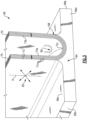
Figure 3 illustrates the fiber ply layup of a blade outer air seal arc segment. -
Figure 1 schematically illustrates agas turbine engine 20. Thegas turbine engine 20 is disclosed herein as a two-spool turbofan that generally incorporates afan section 22, acompressor section 24, acombustor section 26 and aturbine section 28. Thefan section 22 drives air along a bypass flow path B in a bypass duct defined within ahousing 15 such as a fan case or nacelle, and also drives air along a core flow path C for compression and communication into thecombustor section 26 then expansion through theturbine section 28. Although depicted as a two-spool turbofan gas turbine engine in the disclosed non-limiting embodiment, it should be understood that the concepts described herein are not limited to use with two-spool turbofans as the teachings may be applied to other types of turbine engines including three-spool architectures. - The
exemplary engine 20 generally includes alow speed spool 30 and ahigh speed spool 32 mounted for rotation about an engine central longitudinal axis A relative to an enginestatic structure 36 viaseveral bearing systems 38. It should be understood thatvarious bearing systems 38 at various locations may alternatively or additionally be provided, and the location ofbearing systems 38 may be varied as appropriate to the application. - The
low speed spool 30 generally includes aninner shaft 40 that interconnects, a first (or low)pressure compressor 44 and a first (or low)pressure turbine 46. Theinner shaft 40 is connected to thefan 42 through a speed change mechanism, which in exemplarygas turbine engine 20 is illustrated as a gearedarchitecture 48 to drive afan 42 at a lower speed than thelow speed spool 30. Thehigh speed spool 32 includes anouter shaft 50 that interconnects a second (or high)pressure compressor 52 and a second (or high)pressure turbine 54. Acombustor 56 is arranged in theexemplary gas turbine 20 between thehigh pressure compressor 52 and thehigh pressure turbine 54. Amid-turbine frame 57 of the enginestatic structure 36 may be arranged generally between thehigh pressure turbine 54 and thelow pressure turbine 46. Themid-turbine frame 57 further supports bearingsystems 38 in theturbine section 28. Theinner shaft 40 and theouter shaft 50 are concentric and rotate viabearing systems 38 about the engine central longitudinal axis A which is collinear with their longitudinal axes. - The core airflow is compressed by the
low pressure compressor 44 then thehigh pressure compressor 52, mixed and burned with fuel in thecombustor 56, then expanded through thehigh pressure turbine 54 andlow pressure turbine 46. Themid-turbine frame 57 includesairfoils 59 which are in the core airflow path C. Theturbines low speed spool 30 andhigh speed spool 32 in response to the expansion. It will be appreciated that each of the positions of thefan section 22,compressor section 24,combustor section 26,turbine section 28, and fandrive gear system 48 may be varied. For example,gear system 48 may be located aft of the low pressure compressor, or aft of thecombustor section 26 or even aft ofturbine section 28, andfan 42 may be positioned forward or aft of the location ofgear system 48. - The
engine 20 in one example is a high-bypass geared aircraft engine. In a further example, theengine 20 bypass ratio is greater than about six (6), with an example embodiment being greater than about ten (10), and can be less than or equal to about 18.0, or more narrowly can be less than or equal to 16.0. The gearedarchitecture 48 is an epicyclic gear train, such as a planetary gear system or other gear system, with a gear reduction ratio of greater than about 2.3. The gear reduction ratio may be less than or equal to 4.0. Thelow pressure turbine 46 has a pressure ratio that is greater than about five. The low pressure turbine pressure ratio can be less than or equal to 13.0, or more narrowly less than or equal to 12.0. In one disclosed embodiment, theengine 20 bypass ratio is greater than about ten (10:1), the fan diameter is significantly larger than that of thelow pressure compressor 44, and thelow pressure turbine 46 has a pressure ratio that is greater than about five (5:1).Low pressure turbine 46 pressure ratio is pressure measured prior to an inlet oflow pressure turbine 46 as related to the pressure at the outlet of thelow pressure turbine 46 prior to an exhaust nozzle. The gearedarchitecture 48 may be an epicycle gear train, such as a planetary gear system or other gear system, with a gear reduction ratio of greater than about 2.3:1 and less than about 5:1. It should be understood, however, that the above parameters are only exemplary of one embodiment of a geared architecture engine and that the present invention is applicable to other gas turbine engines including direct drive turbofans. - A significant amount of thrust is provided by the bypass flow B due to the high bypass ratio. The
fan section 22 of theengine 20 is designed for a particular flight condition -- typically cruise at about 0.8 Mach and about 35,000 feet (10,668 meters). The flight condition of 0.8 Mach and 35,000 ft (10,668 meters), with the engine at its best fuel consumption - also known as "bucket cruise Thrust Specific Fuel Consumption ('TSFC')" - is the industry standard parameter of lbm of fuel being burned divided by lbf of thrust the engine produces at that minimum point. The engine parameters described above and those in this paragraph are measured at this condition unless otherwise specified. "Low fan pressure ratio" is the pressure ratio across the fan blade alone, without a Fan Exit Guide Vane ("FEGV") system. The low fan pressure ratio as disclosed herein according to one non-limiting embodiment is less than about 1.45, or more narrowly greater than or equal to 1.25. "Low corrected fan tip speed" is the actual fan tip speed in ft/sec divided by an industry standard temperature correction of [(Tram °R) / (518.7 °R)]0.5 (where °R = K x 9/5). The "Low corrected fan tip speed" as disclosed herein according to one non-limiting embodiment is less than about 1150.0 ft / second (350.5 meters/second), and can be greater than or equal to 1000.0 ft / second (304.8 meters/second). -
Figure 2 illustrates a portion of thehigh pressure turbine 54 but is also applicable to thelow pressure turbine 46. This section of theturbine 54 includes a row ofvanes 60 and a second row ofvanes 62 axially spaced from the first row ofvanes 60. There is a row ofrotatable blades 64 axially between the first row ofvanes 60 and the second row ofvanes 62. A row of blade outer air seal arc segments 66 ("BOAS 66") is located axially between the first row ofvanes 60 and the second row ofvanes 62. TheBOAS 66 are arc segments in that they each are arced about the engine central axis A. - Each
BOAS 66 is situated radially outwardly of the row ofblades 64 and is comprised of a ceramic matrix composite body 68 ("CMC body 68"). A CMC material is comprised of ceramic fiber plies 71a in aceramic matrix 71b. Example ceramic matrices are silicon-containing ceramic, such as but not limited to, a silicon carbide (SiC) matrix or a silicon nitride (Si3N4) matrix. Ceramic fibers are formed of bundles of filaments and may include, but are not limited to, silicon carbide (SiC) fibers or silicon nitride (Si3N4) fibers. The CMC may be, but is not limited to, a SiC/SiC ceramic matrix composite in which SiC fiber plies are disposed within a SiC matrix. A fiber ply has a fiber architecture, which refers to an ordered arrangement of the fiber tows relative to one another. For example, the fiber plies 71a may have, but are not limited to, a harness satin weave. In a harness satin weave, the fill direction fibers extend over a plurality of warp direction fibers and then under one warp direction fiber. For instance, in an eight harness satin weave, the fill direction fibers extend over seven warp direction fibers, under one warp direction fiber, and then again over another seven warp direction fibers. As used herein, the angular orientation of a ply is with respect to its warp direction, e.g., in a +/- 45 degree layup the warp direction fibers are oriented at 45 degrees to the reference zero direction (the radial direction in the engine 20). - The
CMC body 68 defines aforward end 68a, anaft end 68b,circumferential sides 68c, acore gaspath side 68d facing the row ofblades 64, and anon-core gaspath side 68e opposite thecore gaspath side 68d. There is a pair offlanges 70 that project radially from thenon-core gaspath side 68e. Theflanges 70 may be substantially parallel to each other. Theflanges 70 are not limited to, but may serve for, mounting theBOAS 68 in theengine 20, such as in a clevis joint or hook-type attachment. - The
forward end 68a of theCMC body 68 abuts at least one of thevanes 60 of the first row ofvanes 60. For instance, each of thevanes 60 includes aplatform 60a with a radially-projectingflange 60b that theCMC body 68 bears against. -
Figure 3 illustrates the layup arrangement of the fiber plies 71a in theflanges 70. In general, the fiber plies 71a are comprised of flange fiber plies 73. Although not shown in detail, the remainder of theBOAS 66 may also be comprised of the fiber plies 71aThe flange fiber plies 73 form, at least in part, theflanges 70. As shown, the flange fiber plies 73 are configured in a U-shape (shaped like a capital letter U) in that there are twoupright legs 73a/73b connected by abottom wall 73c. To form the U-shape, the flange fiber plies 73 bend at the sides of thebottom wall 73c to transition into thelegs 73a/73b. As the fibers are ceramic, the plies 73 are somewhat stiff and limited in the amount of bend before the fibers break or crimp. In particular, thebottom wall 73c has a dual counter arc, represented at 80. That is, thebottom wall 73c has a radially inwardly-facing arc that curves about the engine axis A and a radially outwardly-facing arc that curves in the bend of the U-shape. Due to the compound nature of thedual counter arc 80, there is considerable difficulty in laying-up the flange fiber plies 73 without breakage, crimping, or kinking. - To facilitate mitigation of these concerns, the flange fiber plies 73 have a +/-15-75 degree ply layup arrangement, which is represented at 82. As indicated above, the angular orientations are given with respect to the warp directions of the fiber plies 71a versus a reference zero direction, which here is the radial direction R. In the +/-15-75 degree ply layup arrangement, the flange fiber plies 73 are arranged in alternating orientations. As examples, a +/- 15 layup would have alternating plies of +15 degrees and -15 degrees, and a +/- 75 layup would have alternating plies of +75 degrees and -75 degrees. In such orientations, the fibers of the flange fiber plies 73 are oblique to the each of the two bending directions of the
dual counter arc 80 and can thus bend substantially helically rather than circularly. This permits the fibers, and thus the flange fiber plies 73, to more gradually bend through thedual counter arc 80 without substantial breakage, crimping, or kinking, thereby maintaining greater ply integrity in thefinal BOAS 66 and enabling enhanced producability. In further examples, the flange fiber plies 73 have a layup arrangement of +/- 40-50 degrees to further facilitate helical bending of the fibers. For instance, for "purely helical" bending in which neither the warp or weft fibers are biased toward the zero direction, the layup arrangement may be +/- 45 degrees. Conversely, orientations below 15 degrees or above 75 degrees are not expected to be as effective. - Although a combination of features is shown in the illustrated examples, not all of them need to be combined to realize the benefits of various embodiments of this disclosure. In other words, a system designed according to an embodiment of this disclosure will not necessarily include all of the features shown in any one of the Figures or all of the portions schematically shown in the Figures. Moreover, selected features of one example embodiment may be combined with selected features of other example embodiments.
- The preceding description is exemplary rather than limiting in nature. Variations and modifications to the disclosed examples may become apparent to those skilled in the art that do not necessarily depart from this disclosure. The scope of legal protection given to this disclosure can only be determined by studying the following claims.
Claims (12)
- A gas turbine engine (20) comprising:
a turbine section (28) including,a first vane (60) disposed about an engine axis (A), a second vane (62) axially spaced from the first vane (60), and a blade (64) axially between the first vane (60) and the second vane (62);a blade outer air seal arc segment (66) situated radially outwardly of the blade (64), the blade outer air seal including a ceramic matrix composite body (68) defining a core gaspath side (68d) facing the blade (64), a non-core gaspath side (68e) opposite the core gaspath side (68d), a forward end (68a), an aft end (68b), and circumferential sides (68c), the ceramic matrix composite body (68) having first and second flanges (70) on the non-core gaspath side (68e),the ceramic matrix composite body (68) being comprised of fiber plies (71a) disposed in a ceramic matrix (71b), the fiber plies (71a) including flange fiber plies (73) that have a +/- 15-75 degree ply layup arrangement. - The gas turbine engine (20) as recited in claim 1, wherein the flange fiber plies (73) are configured in a U-shape and the bottom of the U-shape has a dual counter-arc (80).
- The gas turbine engine (20) as recited in claim 1 or 2, wherein the flange fiber plies (73) have a +/- 40-50 degree ply layup arrangement.
- The gas turbine engine (20) as recited in claim 1 or 2, wherein the flange fiber plies (73) have a +/- 45 degree ply layup arrangement.
- The gas turbine engine (20) as recited in any preceding claim, wherein the +/-15-75 degree ply layup arrangement is with respect to a warp direction of the flange fiber plies (73).
- The gas turbine engine (20) as recited in any preceding claim, wherein the +/-15-75 degree ply layup arrangement is with respect to a radial direction (R) perpendicular to the engine axis (A).
- A gas turbine engine article comprising:a blade outer air seal arc segment (66) including a ceramic matrix composite body (68) defining a core gaspath side (68d), a non-core gaspath side (68e) opposite the core gaspath side (68d), a forward end (68a), an aft end (68b), and circumferential sides (68c), the ceramic matrix composite body (68) having first and second flanges (70) on the non-core gaspath side (68e);the ceramic matrix composite body (68) being comprised of fiber plies (71a) disposed in a ceramic matrix (71b), the fiber plies (71a) including flange fiber plies (73) that have a +/- 15-75 degree ply layup arrangement.
- The gas turbine engine (20) article as recited in claim 7, wherein the flange fiber plies (73) at the bottom of the U-shape have a dual counter-arc (80).
- The gas turbine engine (20) article as recited in claim 7, wherein the flange fiber plies (73) are configured in a U-shape and the bottom of the U-shape has a dual counter-arc (80).
- The gas turbine engine (20) article as recited in claim 7, 8 or 9, wherein the flange fiber plies (73) have a +/- 15-75 degree ply layup arrangement.
- The gas turbine engine (20) article as recited in claim 10, wherein the +/- 15-75 degree ply layup arrangement is with respect to a warp direction of the flange fiber plies (73).
- The gas turbine engine (20) article as recited in claim 10 or 11, wherein the +/-15-75 degree ply layup arrangement is with respect to a radial direction (R) perpendicular to an engine axis (A).
Applications Claiming Priority (1)
| Application Number | Priority Date | Filing Date | Title |
|---|---|---|---|
| US18/085,864 US11982187B1 (en) | 2022-12-21 | 2022-12-21 | Blade outer air seal with angle-oriented ply layup for CMC compound radii |
Publications (1)
| Publication Number | Publication Date |
|---|---|
| EP4390060A1 true EP4390060A1 (en) | 2024-06-26 |
Family
ID=89224528
Family Applications (1)
| Application Number | Title | Priority Date | Filing Date |
|---|---|---|---|
| EP23218234.5A Pending EP4390060A1 (en) | 2022-12-21 | 2023-12-19 | Blade outer air seal with angle-oriented ply layup for cmc compound radii |
Country Status (2)
| Country | Link |
|---|---|
| US (1) | US11982187B1 (en) |
| EP (1) | EP4390060A1 (en) |
Families Citing this family (1)
| Publication number | Priority date | Publication date | Assignee | Title |
|---|---|---|---|---|
| US12584418B2 (en) * | 2024-08-15 | 2026-03-24 | Rtx Corporation | CMC component with cooling cavity |
Citations (4)
| Publication number | Priority date | Publication date | Assignee | Title |
|---|---|---|---|---|
| JPH10103013A (en) * | 1996-09-30 | 1998-04-21 | Toshiba Corp | Gas turbine shroud structure |
| EP3608513A1 (en) * | 2018-08-06 | 2020-02-12 | United Technologies Corporation | Blade outer air seal reinforcement laminate |
| US20210095573A1 (en) * | 2019-09-26 | 2021-04-01 | United Technologies Corporation | Double box composite seal assembly for gas turbine engine |
| US20210131302A1 (en) * | 2019-11-06 | 2021-05-06 | United Technologies Corporation | Feather seal slot arrangement for a cmc boas assembly |
Family Cites Families (4)
| Publication number | Priority date | Publication date | Assignee | Title |
|---|---|---|---|---|
| US10370986B2 (en) | 2015-07-24 | 2019-08-06 | General Electric Company | Nozzle and nozzle assembly for gas turbine engine |
| US10689998B2 (en) | 2015-10-14 | 2020-06-23 | General Electric Company | Shrouds and methods for forming turbine components |
| US10196918B2 (en) * | 2016-06-07 | 2019-02-05 | United Technologies Corporation | Blade outer air seal made of ceramic matrix composite |
| US20190284947A1 (en) * | 2018-03-14 | 2019-09-19 | General Electric Company | Cmc shroud segment with interlocking mechanical joints and fabrication |
-
2022
- 2022-12-21 US US18/085,864 patent/US11982187B1/en active Active
-
2023
- 2023-12-19 EP EP23218234.5A patent/EP4390060A1/en active Pending
Patent Citations (4)
| Publication number | Priority date | Publication date | Assignee | Title |
|---|---|---|---|---|
| JPH10103013A (en) * | 1996-09-30 | 1998-04-21 | Toshiba Corp | Gas turbine shroud structure |
| EP3608513A1 (en) * | 2018-08-06 | 2020-02-12 | United Technologies Corporation | Blade outer air seal reinforcement laminate |
| US20210095573A1 (en) * | 2019-09-26 | 2021-04-01 | United Technologies Corporation | Double box composite seal assembly for gas turbine engine |
| US20210131302A1 (en) * | 2019-11-06 | 2021-05-06 | United Technologies Corporation | Feather seal slot arrangement for a cmc boas assembly |
Also Published As
| Publication number | Publication date |
|---|---|
| US11982187B1 (en) | 2024-05-14 |
Similar Documents
| Publication | Publication Date | Title |
|---|---|---|
| EP3816406B1 (en) | Cmc heat shield for a gas turbine | |
| US11215064B2 (en) | Compact pin attachment for CMC components | |
| US20200400032A1 (en) | Boas thermal baffle | |
| EP4283095A1 (en) | Cmc laminate airfoil with ply drops | |
| US11560800B1 (en) | Airfoil with fiber plies having interdigitated fingers in trailing end | |
| EP4124611A1 (en) | Ceramic matrix composite with fiber interfacial coating system | |
| US12055067B2 (en) | Airfoil assembly with fiber-reinforced composite rings and toothed exit slot | |
| EP4030037A1 (en) | Airfoil with wishbone fiber composite structure | |
| EP4390060A1 (en) | Blade outer air seal with angle-oriented ply layup for cmc compound radii | |
| EP4345256B1 (en) | Gas turbine engine and gas turbine engine component | |
| EP4345254A1 (en) | Blade outer air seal with compliant seal | |
| EP4067620B1 (en) | Airfoil with radially-spaced ribs and interlocking tabs, and gas turbine engine | |
| US11649732B2 (en) | Vane assembly with spring device for biasing mate face seal | |
| US12241387B1 (en) | Tilted CMC vane arc segment | |
| US11125099B2 (en) | Boas arrangement with double dovetail attachments | |
| US12234735B1 (en) | CMC BOAS with overlapping seals | |
| US12448896B2 (en) | Localized thickening ply reinforcement within ceramic matrix composite airfoil cavity | |
| EP4345255A1 (en) | Blade outer air seal with retainer ring | |
| US12098643B2 (en) | Chevron grooved mateface seal |
Legal Events
| Date | Code | Title | Description |
|---|---|---|---|
| PUAI | Public reference made under article 153(3) epc to a published international application that has entered the european phase |
Free format text: ORIGINAL CODE: 0009012 |
|
| STAA | Information on the status of an ep patent application or granted ep patent |
Free format text: STATUS: THE APPLICATION HAS BEEN PUBLISHED |
|
| AK | Designated contracting states |
Kind code of ref document: A1 Designated state(s): AL AT BE BG CH CY CZ DE DK EE ES FI FR GB GR HR HU IE IS IT LI LT LU LV MC ME MK MT NL NO PL PT RO RS SE SI SK SM TR |
|
| STAA | Information on the status of an ep patent application or granted ep patent |
Free format text: STATUS: REQUEST FOR EXAMINATION WAS MADE |
|
| 17P | Request for examination filed |
Effective date: 20241220 |
|
| STAA | Information on the status of an ep patent application or granted ep patent |
Free format text: STATUS: EXAMINATION IS IN PROGRESS |