EP4390058A1 - Portable device and method for milling a circumferential brush seal of a gas turbine assembly - Google Patents
Portable device and method for milling a circumferential brush seal of a gas turbine assembly Download PDFInfo
- Publication number
- EP4390058A1 EP4390058A1 EP22425061.3A EP22425061A EP4390058A1 EP 4390058 A1 EP4390058 A1 EP 4390058A1 EP 22425061 A EP22425061 A EP 22425061A EP 4390058 A1 EP4390058 A1 EP 4390058A1
- Authority
- EP
- European Patent Office
- Prior art keywords
- seal
- milling
- casing
- guiding body
- milling tool
- Prior art date
- Legal status (The legal status is an assumption and is not a legal conclusion. Google has not performed a legal analysis and makes no representation as to the accuracy of the status listed.)
- Granted
Links
Images

Classifications
-
- F—MECHANICAL ENGINEERING; LIGHTING; HEATING; WEAPONS; BLASTING
- F01—MACHINES OR ENGINES IN GENERAL; ENGINE PLANTS IN GENERAL; STEAM ENGINES
- F01D—NON-POSITIVE DISPLACEMENT MACHINES OR ENGINES, e.g. STEAM TURBINES
- F01D5/00—Blades; Blade-carrying members; Heating, heat-insulating, cooling or antivibration means on the blades or the members
- F01D5/005—Repairing methods or devices
-
- B—PERFORMING OPERATIONS; TRANSPORTING
- B23—MACHINE TOOLS; METAL-WORKING NOT OTHERWISE PROVIDED FOR
- B23C—MILLING
- B23C1/00—Milling machines not designed for particular work or special operations
- B23C1/20—Portable devices or machines; Hand-driven devices or machines
-
- B—PERFORMING OPERATIONS; TRANSPORTING
- B23—MACHINE TOOLS; METAL-WORKING NOT OTHERWISE PROVIDED FOR
- B23C—MILLING
- B23C3/00—Milling particular work; Special milling operations; Machines therefor
-
- F—MECHANICAL ENGINEERING; LIGHTING; HEATING; WEAPONS; BLASTING
- F01—MACHINES OR ENGINES IN GENERAL; ENGINE PLANTS IN GENERAL; STEAM ENGINES
- F01D—NON-POSITIVE DISPLACEMENT MACHINES OR ENGINES, e.g. STEAM TURBINES
- F01D11/00—Preventing or minimising internal leakage of working-fluid, e.g. between stages
-
- F—MECHANICAL ENGINEERING; LIGHTING; HEATING; WEAPONS; BLASTING
- F05—INDEXING SCHEMES RELATING TO ENGINES OR PUMPS IN VARIOUS SUBCLASSES OF CLASSES F01-F04
- F05D—INDEXING SCHEME FOR ASPECTS RELATING TO NON-POSITIVE-DISPLACEMENT MACHINES OR ENGINES, GAS-TURBINES OR JET-PROPULSION PLANTS
- F05D2240/00—Components
- F05D2240/55—Seals
- F05D2240/56—Brush seals
Definitions
- the present invention relates to the technical field of the gas turbine assembly for power plants.
- a power plant gas turbine assembly in the following only gas turbine
- an incoming air flow is compressed by a compressor and mixed with an added fuel in a combustion chamber for producing a hot gas flow to be expanded in a turbine for generating a rotating work on a rotor in turn connected to a generator.
- the present invention relates to the field of the service for a gas turbine assembly, i.e. the periodic inspection activities carried out in order to check the integrity of the components forming the assembly or the repairing activities carried out in order to repair components for restoring the assembly.
- the service activity related to the present invention refers to operations to be performed for milling a circumferential brush seal of a gas turbine assembly.
- the following description will refer to a portable device and to a method for milling a circumferential brush seal of a gas turbine assembly by using this portable device.
- a gas turbine assembly for power plants comprises a compressor assembly, a combustor assembly and a turbine assembly.
- the compressor assembly is configured for compressing incoming air supplied at a compressor inlet.
- the compressed air leaving the compressor assembly flows into a volume (called "plenum") and from there into the combustor assembly.
- This combustor assembly comprises usually a plurality of burners configured for injecting fuel (oil and/or gas fuel) in the compressed air flow.
- the mixture of fuel and compressed air enters a combustion chamber where this mixture is combusted.
- the resulting hot gas flow leaves the combustion chamber and drives in rotation the turbine assembly that performs a work on the rotor (in turn connected to a power generator).
- the turbine assembly comprises a plurality of stages, or rows, of rotating blades that are interposed by a plurality of stages, or rows, of stator vanes.
- the rotating blades are supported by the rotor whereas the stator vanes are supported by a casing (called “vane carrier”) that is concentric and surrounding the turbine assembly.
- a sequential gas turbine comprises a first and a second combustor or a first and a second combustion stage wherein each combustor is provided with a plurality of burners and with at least a relative combustion chamber.
- the first and the second combustor are annular shaped and are physically separated by a stage of turbine blades, called high pressure turbine.
- a second turbine unit Downstream the second combustor a second turbine unit is present (called low pressure turbine).
- the gas turbine is not provided with the high pressure turbine and the combustor assembly is realized in form of a plurality of can-combustors arranged as a ring around the rotor.
- Each can-combustor comprises a first combustor and a second combustor arranged directly one downstream the other inside a common can shaped casing.
- a circumferential brush seal is a seal made of a metallic material housed in a circumferential groove obtained in the gas turbine casing.
- a circumferential brush seal comprises an outer portion constrained, for instance by a mechanical coupling, inside the casing groove and an inner portion brush shaped protruding from the casing towards the turbine axis.
- the brush portion of the seal is exposed and needs to be periodically milled for restoring its original features.
- the skilled person of this field well knows what a circumferential brush seal is and thus additional details are not required for the correct understanding of the context of the present invention.
- a primary object of the present invention is to provide a portable device for milling a circumferential brush seal of a gas turbine assembly, wherein this portable device is configured for being used onsite ("in-situ") in order to avoid the moving of the system and the removal of the seal from its groove.
- portable we mean a device that can be used by hand by a user without requiring the seal removal acting directly on the inner surface of the casing at the seal.
- the present invention may also be defined as an alternative method for milling a circumferential brush seal of a gas turbine assembly. Indeed, the prior art practice does not suggest to perform this milling step onsite leaving the seal housed inside its casing groove.
- the present invention also provides a method for milling a circumferential brush seal of a gas turbine assembly, wherein the method comprises the steps of:
- the invention involves a reliable and efficient method performed by using a handy (portable and able to be used directly in contact with the casing) milling tool for milling the circumferential brush seal.
- a handy (portable and able to be used directly in contact with the casing) milling tool for milling the circumferential brush seal.
- the circumferential brush seal is milled leaving the seal into its seat.
- the Applicant developed a new portable device suitable for performing the method of the invention, i.e. a device configured for milling a circumferential brush seal of a gas turbine assembly when the seal is still housed in its seat obtained in the inner surface of the turbine casing. Therefore, the portable device according to the main definition of the invention comprises:
- the device comprises a motor for driving the rotation of the milling tool.
- a motor for driving the rotation of the milling tool for instance an adjustable pneumatic motor can be provided and controlled by the handle.
- the milling tool is ogive-shaped having an axis that in use is parallel to the turbine axis orthogonal to the seal.
- the milling tool is movable along a radial direction.
- the milling tool is driven in a such a way that the removed parts of the seal during the milling are forced to be raised from the casing surface.
- the milling tool is arranged at a front portion of the guiding body.
- the device comprises a magnetic surface arranged in the proximity of the milling tool so that the removed parts of the seal during the milling are attracted and collected on this magnetic surface.
- the guiding body is commutable into a plurality of different configurations for matching turbine casings having different shape or radius.
- the guiding body comprises a front and a rear body connected each other in a pivoting manner.
- the guiding body is realized in form of two parallel plates wherein in use the seal is arranged between the two plates.
- the surface of guiding body configured to go in contact with the casing comprises at least a magnet and/or at least a ball.
- figure 1 is a schematic view of a power plant gas turbine assembly that may be improved by the present invention.
- a gas turbine assembly is an assembly 1 as comprising:
- Figure 2 is a schematic view of a brush seal 10 housed in a casing groove.
- figure 2 discloses a portion of a turbine casing 7 comprising an inner surface 8 wherein a circumferential groove 9 has been obtained.
- the references with arrows C and A refers to the axial direction A and to the circumferential direction C. These directions, and the third radial direction, are well known by the skilled person in the art.
- the seal 10 comprises an inner portion 11 constrained into the groove 9 and an outer portion 12 (brush shaped) protruding from the casing.
- the shape of the groove 9 and the shape of the seal 10 disclosed in figure 2 are only not limiting examples.
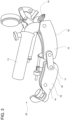
- Figure 3 is a first view of an example of a portable device 20 according to the present invention.
- the scope of this device 20 is to mill the seal 10, in particular its brush portion 12, leaving the seal 10 inside the groove 9.
- the device 20 comprises an handle 13 coupled to a guiding body 14.
- the guiding body 14 comprises a circular surface 18 for sliding along the circumferential direction on the casing and it is realized in form of two bodies 15 16. These two bodies are connected each other in a pivoting 17 manner so that the guiding body 14 may vary its shape to match different casing profiles.
- Each body 15 16 forming the guiding body 14 comprises two parallel plates (the distance may be adjusted) so that the seal 10 may stay between the plates during the use of the device 20.
- the matching surface 18 of the guiding body 14 is circular shaped according to the circular shape of the casing.
- the front portion of the device 20 is provided with a milling tool 19 ogive-shaped having a rotation axis orthogonal to the guiding direction of the guiding body 14 and to extent of the seal 10 to be milled.
- the rotation axis of the milling tool 19 is parallel to the axial direction of the gas turbine.
- This milling tool 19 is connected to a pneumatic motor 21 supported by the handle 13 so that during the movement of the device 20 along the casing the milling tool 19 mills the brush portion 12 of the seal 10.
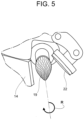
- Figure 5 is an enlarged view of the device 20 disclosing the milling tool 19.
- the direction of rotation of the milling tool 19 is represented with the reference R and this direction of rotation forces the removed portions of the seal 10 toward a magnetic surface 22 arranged near to the milling tool 19.
- the position of the milling tool 19 with respect to the guiding body 14 may vary as also the relative position between the milling tool 19 and the magnetic surface 22 may vary.
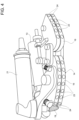
- Figure 4 is a second view of the portable device 20 of figure 3 disclosing the portion 18 of the guiding body 14 configured to go in contact with the casing.
- the portion 18 of the guiding body 14 configured to go in contact with the casing is provided with a plurality of magnets 23 and balls 24 for allowing a safe coupling and movement of the device 20 along the casing.
Landscapes
- Engineering & Computer Science (AREA)
- Mechanical Engineering (AREA)
- General Engineering & Computer Science (AREA)
- Sealing Using Fluids, Sealing Without Contact, And Removal Of Oil (AREA)
- Sealing Devices (AREA)
- Turbine Rotor Nozzle Sealing (AREA)
Abstract
- providing a portable device that comprises a milling tool and a guiding body configured to circumferentially slide along the casing; - putting in contact the portable device with the inner surface of the casing where the circumferential brush seal is present; - milling the circumferential brush seal by circumferentially moving the portable device along the seal leaving the seal housed inside its casing groove.
Description
- The present invention relates to the technical field of the gas turbine assembly for power plants. As known, in a power plant gas turbine assembly (in the following only gas turbine) an incoming air flow is compressed by a compressor and mixed with an added fuel in a combustion chamber for producing a hot gas flow to be expanded in a turbine for generating a rotating work on a rotor in turn connected to a generator. In particular, the present invention relates to the field of the service for a gas turbine assembly, i.e. the periodic inspection activities carried out in order to check the integrity of the components forming the assembly or the repairing activities carried out in order to repair components for restoring the assembly. More in detail, the service activity related to the present invention refers to operations to be performed for milling a circumferential brush seal of a gas turbine assembly. In view of the above preliminary considerations related to the technical field of the present invention, the following description will refer to a portable device and to a method for milling a circumferential brush seal of a gas turbine assembly by using this portable device.
- As known, a gas turbine assembly for power plants comprises a compressor assembly, a combustor assembly and a turbine assembly. The compressor assembly is configured for compressing incoming air supplied at a compressor inlet. The compressed air leaving the compressor assembly flows into a volume (called "plenum") and from there into the combustor assembly. This combustor assembly comprises usually a plurality of burners configured for injecting fuel (oil and/or gas fuel) in the compressed air flow. The mixture of fuel and compressed air enters a combustion chamber where this mixture is combusted. The resulting hot gas flow leaves the combustion chamber and drives in rotation the turbine assembly that performs a work on the rotor (in turn connected to a power generator). As known, the turbine assembly comprises a plurality of stages, or rows, of rotating blades that are interposed by a plurality of stages, or rows, of stator vanes. The rotating blades are supported by the rotor whereas the stator vanes are supported by a casing (called "vane carrier") that is concentric and surrounding the turbine assembly.
- In order to achieve a high efficiency, the hot gas flow has to disclose a very high turbine inlet temperature. However, in general this high temperature involves an undesired high NOx emission level. In order to reduce this emission and to increase operational flexibility without decreasing the efficiency, a so called "sequential" gas turbine is particularly suitable. In general, a sequential gas turbine comprises a first and a second combustor or a first and a second combustion stage wherein each combustor is provided with a plurality of burners and with at least a relative combustion chamber. Today at least two different kinds of sequential gas turbines are known. According to a first embodiment, the first and the second combustor are annular shaped and are physically separated by a stage of turbine blades, called high pressure turbine. Downstream the second combustor a second turbine unit is present (called low pressure turbine). According to a second embodiment of a sequential gas turbine, the gas turbine is not provided with the high pressure turbine and the combustor assembly is realized in form of a plurality of can-combustors arranged as a ring around the rotor. Each can-combustor comprises a first combustor and a second combustor arranged directly one downstream the other inside a common can shaped casing. These two example of gas turbine assemblies have been cited only as non-limiting examples wherein the present invention can be applied. Indeed, the present invention may be applied in any gas turbine assembly provided that at least a circumferential brush seal is present to be periodically milled.
- Substantially all gas turbine assemblies are provided with circumferential brush seals. A circumferential brush seal is a seal made of a metallic material housed in a circumferential groove obtained in the gas turbine casing. A circumferential brush seal comprises an outer portion constrained, for instance by a mechanical coupling, inside the casing groove and an inner portion brush shaped protruding from the casing towards the turbine axis. Thus, the brush portion of the seal is exposed and needs to be periodically milled for restoring its original features. The skilled person of this field well knows what a circumferential brush seal is and thus additional details are not required for the correct understanding of the context of the present invention.
- The prior art practice for restoring the circumferential brush seal by milling its brush portion requires to remove the seal form the casing and put the seal in a separate milling apparatus. Of course, after the milling step, the restored seal has to be housed again inside its casing groove. As self-evident, this prior art involves the drawback of requiring the stop of the system and the moving of the system to the service point where the separate milling apparatus is present.
- Thus, today there is the need to implement a new practice for restoring the circumferential brush seal by milling its brush portion wherein the stop of the system is reduced and the milling is performed in situ avoiding the moving of the system and the removal of the seal from its groove.
- Accordingly, a primary object of the present invention is to provide a portable device for milling a circumferential brush seal of a gas turbine assembly, wherein this portable device is configured for being used onsite ("in-situ") in order to avoid the moving of the system and the removal of the seal from its groove. With the term "portable" we mean a device that can be used by hand by a user without requiring the seal removal acting directly on the inner surface of the casing at the seal.
- Before entering into the mechanical details of the portable device, the present invention may also be defined as an alternative method for milling a circumferential brush seal of a gas turbine assembly. Indeed, the prior art practice does not suggest to perform this milling step onsite leaving the seal housed inside its casing groove.
- Therefore, the present invention also provides a method for milling a circumferential brush seal of a gas turbine assembly, wherein the method comprises the steps of:
- a) providing a portable device that (as will be described in the following) comprises a milling tool;
- b) putting in contact the portable device with the inner surface of the casing where the circumferential brush seal is present;
- c) milling the circumferential brush seal by circumferentially moving the portable device along the seal leaving the seal housed inside its casing groove.
- Thus, the invention involves a reliable and efficient method performed by using a handy (portable and able to be used directly in contact with the casing) milling tool for milling the circumferential brush seal. Please be noted that in a traditional milling process of this seal required the removal of the seal from its seat. On the contrary, according to the present invention the circumferential brush seal is milled leaving the seal into its seat.
- As foregoing cited, the Applicant developed a new portable device suitable for performing the method of the invention, i.e. a device configured for milling a circumferential brush seal of a gas turbine assembly when the seal is still housed in its seat obtained in the inner surface of the turbine casing. Therefore, the portable device according to the main definition of the invention comprises:
- a handle configured for being maneuvered by a user; this handle allows the user to put the device in contact with the inner surface of the turbine casing where the seal is present and to circumferentially move the device along the seal;
- a guiding body configured to match the inner surface of the turbine casing for guiding the device during its movements along the seal be casing at the brush seal;
- a milling tool configured for milling the circumferential brush seal during the movement of the device along the seal.
- Preferably, the device comprises a motor for driving the rotation of the milling tool. For instance an adjustable pneumatic motor can be provided and controlled by the handle.
- Preferably, the milling tool is ogive-shaped having an axis that in use is parallel to the turbine axis orthogonal to the seal.
- Preferably, the milling tool is movable along a radial direction.
- Preferably, the milling tool is driven in a such a way that the removed parts of the seal during the milling are forced to be raised from the casing surface.
- Preferably, the milling tool is arranged at a front portion of the guiding body.
- Preferably, the device comprises a magnetic surface arranged in the proximity of the milling tool so that the removed parts of the seal during the milling are attracted and collected on this magnetic surface.
- Preferably, the guiding body is commutable into a plurality of different configurations for matching turbine casings having different shape or radius.
- Preferably, the guiding body comprises a front and a rear body connected each other in a pivoting manner.
- Preferably, the guiding body is realized in form of two parallel plates wherein in use the seal is arranged between the two plates.
- Preferably, the surface of guiding body configured to go in contact with the casing comprises at least a magnet and/or at least a ball.
- It is to be understood that both the foregoing general description and the following detailed description are exemplary, and are intended to provide further explanation of the invention as claimed. Other advantages and features of the invention will be apparent from the following description, drawings and claims.
- The features of the invention believed to be novel are set forth with particularity in the appended claims.
- Further benefits and advantages of the present invention will become apparent after a careful reading of the detailed description with appropriate reference to the accompanying drawings.
- The invention itself, however, may be best understood by reference to the following detailed description of the invention, which describes an exemplary embodiment of the invention, taken in conjunction with the accompanying drawings, in which:
-
figure 1 is a schematic view of a gas turbine assembly for power plants; -
figure 2 is a schematic view of a brush seal housed in a casing groove; -
figure 3 is a first view of an example of a portable device according to the present invention; -
figure 4 is a second view of the portable device offigure 3 disclosing the portion configured to go in contact with the casing; -
figure 5 is an enlarged view of a component of the portable device offigure 3 . - In cooperation with attached drawings, the technical contents and detailed description of the present invention are described thereinafter according to preferred embodiments, being not used to limit its executing scope. Any equivalent variation and modification made according to appended claims is all covered by the claims claimed by the present invention.
- Reference will now be made to the drawing figures to describe the present invention in detail. In particular, reference is made to
figure 1 which is a schematic view of a power plant gas turbine assembly that may be improved by the present invention. In general, no particular feature is required for providing a power plant gas turbine assembly suitable to be improved by the present invention. Generally, a gas turbine assembly is an assembly 1 as comprising: - a
compressor 2 for compressing air; - a
combustion chamber 3 for generating a hot gas flow having a main direction M; - a
turbine 4 driven by the hot gas flow for rotating arotor 5; - a
generator 6 for converting the rotating work of therotor 5. -
Figure 2 is a schematic view of abrush seal 10 housed in a casing groove. In particular,figure 2 discloses a portion of a turbine casing 7 comprising aninner surface 8 wherein acircumferential groove 9 has been obtained. Infigure 2 the references with arrows C and A refers to the axial direction A and to the circumferential direction C. These directions, and the third radial direction, are well known by the skilled person in the art. Inside the groove 9 abrush seal 10 is arranged. As disclosed, theseal 10 comprises aninner portion 11 constrained into thegroove 9 and an outer portion 12 (brush shaped) protruding from the casing. The shape of thegroove 9 and the shape of theseal 10 disclosed infigure 2 are only not limiting examples. -
Figure 3 is a first view of an example of aportable device 20 according to the present invention. The scope of thisdevice 20 is to mill theseal 10, in particular itsbrush portion 12, leaving theseal 10 inside thegroove 9. As disclosed infigure 3 , thedevice 20 comprises anhandle 13 coupled to a guidingbody 14. The guidingbody 14 comprises acircular surface 18 for sliding along the circumferential direction on the casing and it is realized in form of twobodies 15 16. These two bodies are connected each other in a pivoting 17 manner so that the guidingbody 14 may vary its shape to match different casing profiles. Eachbody 15 16 forming the guidingbody 14 comprises two parallel plates (the distance may be adjusted) so that theseal 10 may stay between the plates during the use of thedevice 20. The matchingsurface 18 of the guidingbody 14 is circular shaped according to the circular shape of the casing. The front portion of thedevice 20 is provided with amilling tool 19 ogive-shaped having a rotation axis orthogonal to the guiding direction of the guidingbody 14 and to extent of theseal 10 to be milled. In use the rotation axis of themilling tool 19 is parallel to the axial direction of the gas turbine. Thismilling tool 19 is connected to apneumatic motor 21 supported by thehandle 13 so that during the movement of thedevice 20 along the casing themilling tool 19 mills thebrush portion 12 of theseal 10.Figure 5 is an enlarged view of thedevice 20 disclosing themilling tool 19. In this figure the direction of rotation of themilling tool 19 is represented with the reference R and this direction of rotation forces the removed portions of theseal 10 toward amagnetic surface 22 arranged near to themilling tool 19. In this example, the position of themilling tool 19 with respect to the guidingbody 14 may vary as also the relative position between themilling tool 19 and themagnetic surface 22 may vary. -
Figure 4 is a second view of theportable device 20 offigure 3 disclosing theportion 18 of the guidingbody 14 configured to go in contact with the casing. According to this example, theportion 18 of the guidingbody 14 configured to go in contact with the casing is provided with a plurality ofmagnets 23 andballs 24 for allowing a safe coupling and movement of thedevice 20 along the casing. - Although the invention has been explained in relation to its preferred embodiment(s) as mentioned above, it is to be understood that many other possible modifications and variations can be made without departing from the scope of the present invention. It is, therefore, contemplated that the appended claim or claims will cover such modifications and variations that fall within the true scope of the invention.
Claims (13)
- A method for milling a circumferential brush seal (10) housed in a casing groove of a gas turbine assembly, wherein the method comprises the steps of:a) providing a portable device (20) that comprises a milling tool (19) and a guiding body (14) configured to circumferentially slide along the casing;b) putting in contact the portable device (20) with the inner surface of the casing where the circumferential brush seal (10) is present;c) milling the circumferential brush seal (10) by circumferentially moving the portable device (20) along the seal (10) leaving the seal (10) housed inside its casing groove.
- A portable device for milling a circumferential brush seal (10) housed in a circumferential seat obtained in an inner surface of a turbine casing of a gas turbine assembly, wherein the portable device (20) comprises:- a handle (13) configured for being maneuvered by a user so that the user can put the device (20) in contact with the inner surface of the turbine casing where the seal (10) is present and circumferentially move the device (20) along the seal (10);- a guiding body (14) configured to match the inner surface of the turbine casing for guiding the device (20) during its movements along the seal (10);- a milling tool (19) configured for milling the circumferential brush seal (10) during the movement of the device (20) along the seal (10) leaving the seal (10) in its seat.
- Device as claimed in claim 2, wherein it comprises a motor (21), preferably an adjustable pneumatic motor, for driving the rotation of the milling tool (19).
- Device as claimed in any one of the foregoing claims, wherein the milling tool (19) is ogive-shaped having an axis that in use is orthogonal to guiding direction defined by the guiding body (14).
- Device as claimed in any one of the foregoing claims, wherein the milling tool (19) is movable in an adjustable manner with respect to the guiding body (14).
- Device as claimed in any one of the foregoing claims, wherein the milling tool (19) is driven along a direction of rotation (R) so that the removed parts of the seal (10) during the milling step are forced to be raised from the casing surface.
- Device as claimed in any one of the foregoing claims, wherein the milling tool (19) is arranged at a front portion of the guiding body (14).
- Device as claimed in claim 6 or 7, wherein it comprises a magnetic surface (22) arranged in the proximity of the milling tool (19) so that the removed parts of the seal (10) during the milling step are attracted and collected on the magnetic surface (22).
- Device as claimed in any one of the foregoing claims, wherein the guiding body (14) is commutable into a plurality of different configurations for matching turbine casings having different circumferential shape or radius.
- Device as claimed claim 9, wherein the guiding body (14) comprises two bodies (15, 16) connected each other in a pivoting manner (17).
- Device as claimed claim 10, wherein each body (15, 16) of the guiding body (14) is realized in form of two parallel plates so that in use the seal (10) is arranged between the two plates.
- Device as claimed claim 11, wherein the distance between the plates is adjustable.
- Device as claimed in any one of the foregoing claims, wherein the surface (18) of the guiding body (14) configured to go in contact with the casing comprises at least a magnet (23) and/or at least a ball (24).
Priority Applications (2)
| Application Number | Priority Date | Filing Date | Title |
|---|---|---|---|
| EP22425061.3A EP4390058B1 (en) | 2022-12-22 | 2022-12-22 | Portable device and method for milling a circumferential brush seal of a gas turbine assembly |
| CN202311767899.5A CN118237640A (en) | 2022-12-22 | 2023-12-21 | Portable apparatus and method for milling circumferential brush seals of gas turbine components |
Applications Claiming Priority (1)
| Application Number | Priority Date | Filing Date | Title |
|---|---|---|---|
| EP22425061.3A EP4390058B1 (en) | 2022-12-22 | 2022-12-22 | Portable device and method for milling a circumferential brush seal of a gas turbine assembly |
Publications (2)
| Publication Number | Publication Date |
|---|---|
| EP4390058A1 true EP4390058A1 (en) | 2024-06-26 |
| EP4390058B1 EP4390058B1 (en) | 2025-10-15 |
Family
ID=85121951
Family Applications (1)
| Application Number | Title | Priority Date | Filing Date |
|---|---|---|---|
| EP22425061.3A Active EP4390058B1 (en) | 2022-12-22 | 2022-12-22 | Portable device and method for milling a circumferential brush seal of a gas turbine assembly |
Country Status (2)
| Country | Link |
|---|---|
| EP (1) | EP4390058B1 (en) |
| CN (1) | CN118237640A (en) |
Citations (3)
| Publication number | Priority date | Publication date | Assignee | Title |
|---|---|---|---|---|
| US6318728B1 (en) * | 1997-07-11 | 2001-11-20 | Demag Delaval Turbomachinery Corporation | Brush-seal designs for elastic fluid turbines |
| US6681486B2 (en) * | 1999-12-24 | 2004-01-27 | Cross Manufacturing Company (1938) Limited | Method of forming brush seals between rotating components |
| US20080217859A1 (en) * | 2007-03-05 | 2008-09-11 | United Technologies Corporation | Speed fit brush seal |
-
2022
- 2022-12-22 EP EP22425061.3A patent/EP4390058B1/en active Active
-
2023
- 2023-12-21 CN CN202311767899.5A patent/CN118237640A/en active Pending
Patent Citations (3)
| Publication number | Priority date | Publication date | Assignee | Title |
|---|---|---|---|---|
| US6318728B1 (en) * | 1997-07-11 | 2001-11-20 | Demag Delaval Turbomachinery Corporation | Brush-seal designs for elastic fluid turbines |
| US6681486B2 (en) * | 1999-12-24 | 2004-01-27 | Cross Manufacturing Company (1938) Limited | Method of forming brush seals between rotating components |
| US20080217859A1 (en) * | 2007-03-05 | 2008-09-11 | United Technologies Corporation | Speed fit brush seal |
Also Published As
| Publication number | Publication date |
|---|---|
| CN118237640A (en) | 2024-06-25 |
| EP4390058B1 (en) | 2025-10-15 |
Similar Documents
| Publication | Publication Date | Title |
|---|---|---|
| EP3296520B1 (en) | Non-contact seal with removal features | |
| EP1835147B1 (en) | Fan assembly and corresponding gas turbine engine | |
| US10677074B2 (en) | Method for carrying out work on a rotor and associated foil | |
| US7334331B2 (en) | Methods and apparatus for machining components | |
| US10239132B2 (en) | Machining tool | |
| CN109026178B (en) | Seal for a turbine engine | |
| KR20140138877A (en) | Apparatus and method for servicing turbomachinery components in-situ | |
| EP3208418B1 (en) | System for repairing a bend in a turbine blade | |
| US20190003339A1 (en) | Method of disassembling and assembling gas turbine and gas turbine assembled thereby | |
| EP2339116B1 (en) | Repair of integrally bladed rotors | |
| US20130042474A1 (en) | Rotor seal wire groove repair | |
| EP1757774A2 (en) | Gas turbine rotor blade assembly and corresponding gas turbine | |
| EP4390058A1 (en) | Portable device and method for milling a circumferential brush seal of a gas turbine assembly | |
| US8888418B2 (en) | Fan rub strip in situ machining system and method | |
| EP4227490B1 (en) | Tooling assembly for t-shaped interstage seal installation | |
| US20140271109A1 (en) | Axial compressor and method for controlling stage-to-stage leakage therein | |
| EP4390057A1 (en) | Portable device and method for extracting a circumferential seal from its seat, in particular a labyrinth seal, in a turbine power plant assembly | |
| CN112211680A (en) | Turbine engine with seals | |
| JP7208428B1 (en) | Mounting jigs and jig sets for stator vane blocks and shroud blocks in gas turbine casings | |
| EP4198265A1 (en) | Vane for a gas turbine assembly for power plant and gas turbine assembly for power plant comprising such a vane | |
| CN120862300A (en) | Separation tool and method for nozzle section of gas turbine | |
| US20210123358A1 (en) | Spline seal for disk post | |
| JP2021099097A (en) | Improved patching and usage | |
| EP3163015A1 (en) | Power nozzle repair with cooling hardware installed |
Legal Events
| Date | Code | Title | Description |
|---|---|---|---|
| PUAI | Public reference made under article 153(3) epc to a published international application that has entered the european phase |
Free format text: ORIGINAL CODE: 0009012 |
|
| STAA | Information on the status of an ep patent application or granted ep patent |
Free format text: STATUS: THE APPLICATION HAS BEEN PUBLISHED |
|
| AK | Designated contracting states |
Kind code of ref document: A1 Designated state(s): AL AT BE BG CH CY CZ DE DK EE ES FI FR GB GR HR HU IE IS IT LI LT LU LV MC ME MK MT NL NO PL PT RO RS SE SI SK SM TR |
|
| STAA | Information on the status of an ep patent application or granted ep patent |
Free format text: STATUS: REQUEST FOR EXAMINATION WAS MADE |
|
| 17P | Request for examination filed |
Effective date: 20241224 |
|
| GRAP | Despatch of communication of intention to grant a patent |
Free format text: ORIGINAL CODE: EPIDOSNIGR1 |
|
| STAA | Information on the status of an ep patent application or granted ep patent |
Free format text: STATUS: GRANT OF PATENT IS INTENDED |
|
| INTG | Intention to grant announced |
Effective date: 20250516 |
|
| GRAS | Grant fee paid |
Free format text: ORIGINAL CODE: EPIDOSNIGR3 |
|
| GRAA | (expected) grant |
Free format text: ORIGINAL CODE: 0009210 |
|
| STAA | Information on the status of an ep patent application or granted ep patent |
Free format text: STATUS: THE PATENT HAS BEEN GRANTED |
|
| P01 | Opt-out of the competence of the unified patent court (upc) registered |
Free format text: CASE NUMBER: UPC_APP_4713_4390058/2025 Effective date: 20250826 |
|
| AK | Designated contracting states |
Kind code of ref document: B1 Designated state(s): AL AT BE BG CH CY CZ DE DK EE ES FI FR GB GR HR HU IE IS IT LI LT LU LV MC ME MK MT NL NO PL PT RO RS SE SI SK SM TR |
|
| REG | Reference to a national code |
Ref country code: GB Ref legal event code: FG4D Ref country code: CH Ref legal event code: F10 Free format text: ST27 STATUS EVENT CODE: U-0-0-F10-F00 (AS PROVIDED BY THE NATIONAL OFFICE) Effective date: 20251015 |
|
| REG | Reference to a national code |
Ref country code: IE Ref legal event code: FG4D |
|
| REG | Reference to a national code |
Ref country code: DE Ref legal event code: R096 Ref document number: 602022023016 Country of ref document: DE |
|
| PGFP | Annual fee paid to national office [announced via postgrant information from national office to epo] |
Ref country code: AT Payment date: 20260113 Year of fee payment: 4 |
|
| REG | Reference to a national code |
Ref country code: NL Ref legal event code: MP Effective date: 20251015 |
|
| REG | Reference to a national code |
Ref country code: AT Ref legal event code: MK05 Ref document number: 1847125 Country of ref document: AT Kind code of ref document: T Effective date: 20251015 |
|
| PG25 | Lapsed in a contracting state [announced via postgrant information from national office to epo] |
Ref country code: NL Free format text: LAPSE BECAUSE OF FAILURE TO SUBMIT A TRANSLATION OF THE DESCRIPTION OR TO PAY THE FEE WITHIN THE PRESCRIBED TIME-LIMIT Effective date: 20251015 |
|
| PG25 | Lapsed in a contracting state [announced via postgrant information from national office to epo] |
Ref country code: ES Free format text: LAPSE BECAUSE OF FAILURE TO SUBMIT A TRANSLATION OF THE DESCRIPTION OR TO PAY THE FEE WITHIN THE PRESCRIBED TIME-LIMIT Effective date: 20251015 |
|
| REG | Reference to a national code |
Ref country code: LT Ref legal event code: MG9D |
|
| PG25 | Lapsed in a contracting state [announced via postgrant information from national office to epo] |
Ref country code: NO Free format text: LAPSE BECAUSE OF FAILURE TO SUBMIT A TRANSLATION OF THE DESCRIPTION OR TO PAY THE FEE WITHIN THE PRESCRIBED TIME-LIMIT Effective date: 20260115 |
|
| PGFP | Annual fee paid to national office [announced via postgrant information from national office to epo] |
Ref country code: DE Payment date: 20251222 Year of fee payment: 4 |
|
| PG25 | Lapsed in a contracting state [announced via postgrant information from national office to epo] |
Ref country code: AT Free format text: LAPSE BECAUSE OF FAILURE TO SUBMIT A TRANSLATION OF THE DESCRIPTION OR TO PAY THE FEE WITHIN THE PRESCRIBED TIME-LIMIT Effective date: 20251015 Ref country code: FI Free format text: LAPSE BECAUSE OF FAILURE TO SUBMIT A TRANSLATION OF THE DESCRIPTION OR TO PAY THE FEE WITHIN THE PRESCRIBED TIME-LIMIT Effective date: 20251015 Ref country code: HR Free format text: LAPSE BECAUSE OF FAILURE TO SUBMIT A TRANSLATION OF THE DESCRIPTION OR TO PAY THE FEE WITHIN THE PRESCRIBED TIME-LIMIT Effective date: 20251015 |
|
| PGFP | Annual fee paid to national office [announced via postgrant information from national office to epo] |
Ref country code: IT Payment date: 20251231 Year of fee payment: 4 |
|
| PG25 | Lapsed in a contracting state [announced via postgrant information from national office to epo] |
Ref country code: RS Free format text: LAPSE BECAUSE OF FAILURE TO SUBMIT A TRANSLATION OF THE DESCRIPTION OR TO PAY THE FEE WITHIN THE PRESCRIBED TIME-LIMIT Effective date: 20260115 |
|
| PG25 | Lapsed in a contracting state [announced via postgrant information from national office to epo] |
Ref country code: IS Free format text: LAPSE BECAUSE OF FAILURE TO SUBMIT A TRANSLATION OF THE DESCRIPTION OR TO PAY THE FEE WITHIN THE PRESCRIBED TIME-LIMIT Effective date: 20260215 |
|
| PG25 | Lapsed in a contracting state [announced via postgrant information from national office to epo] |
Ref country code: PT Free format text: LAPSE BECAUSE OF FAILURE TO SUBMIT A TRANSLATION OF THE DESCRIPTION OR TO PAY THE FEE WITHIN THE PRESCRIBED TIME-LIMIT Effective date: 20260216 |
|
| PG25 | Lapsed in a contracting state [announced via postgrant information from national office to epo] |
Ref country code: PL Free format text: LAPSE BECAUSE OF FAILURE TO SUBMIT A TRANSLATION OF THE DESCRIPTION OR TO PAY THE FEE WITHIN THE PRESCRIBED TIME-LIMIT Effective date: 20251015 |
|
| PG25 | Lapsed in a contracting state [announced via postgrant information from national office to epo] |
Ref country code: LV Free format text: LAPSE BECAUSE OF FAILURE TO SUBMIT A TRANSLATION OF THE DESCRIPTION OR TO PAY THE FEE WITHIN THE PRESCRIBED TIME-LIMIT Effective date: 20251015 |