EP4390057A1 - Portable device and method for extracting a circumferential seal from its seat, in particular a labyrinth seal, in a turbine power plant assembly - Google Patents
Portable device and method for extracting a circumferential seal from its seat, in particular a labyrinth seal, in a turbine power plant assembly Download PDFInfo
- Publication number
- EP4390057A1 EP4390057A1 EP22425060.5A EP22425060A EP4390057A1 EP 4390057 A1 EP4390057 A1 EP 4390057A1 EP 22425060 A EP22425060 A EP 22425060A EP 4390057 A1 EP4390057 A1 EP 4390057A1
- Authority
- EP
- European Patent Office
- Prior art keywords
- seal
- winding wheel
- casing
- extracted
- pinching
- Prior art date
- Legal status (The legal status is an assumption and is not a legal conclusion. Google has not performed a legal analysis and makes no representation as to the accuracy of the status listed.)
- Pending
Links
Images


Classifications
-
- F—MECHANICAL ENGINEERING; LIGHTING; HEATING; WEAPONS; BLASTING
- F01—MACHINES OR ENGINES IN GENERAL; ENGINE PLANTS IN GENERAL; STEAM ENGINES
- F01D—NON-POSITIVE DISPLACEMENT MACHINES OR ENGINES, e.g. STEAM TURBINES
- F01D5/00—Blades; Blade-carrying members; Heating, heat-insulating, cooling or antivibration means on the blades or the members
- F01D5/005—Repairing methods or devices
-
- F—MECHANICAL ENGINEERING; LIGHTING; HEATING; WEAPONS; BLASTING
- F01—MACHINES OR ENGINES IN GENERAL; ENGINE PLANTS IN GENERAL; STEAM ENGINES
- F01D—NON-POSITIVE DISPLACEMENT MACHINES OR ENGINES, e.g. STEAM TURBINES
- F01D25/00—Component parts, details, or accessories, not provided for in, or of interest apart from, other groups
- F01D25/28—Supporting or mounting arrangements, e.g. for turbine casing
-
- B—PERFORMING OPERATIONS; TRANSPORTING
- B25—HAND TOOLS; PORTABLE POWER-DRIVEN TOOLS; MANIPULATORS
- B25B—TOOLS OR BENCH DEVICES NOT OTHERWISE PROVIDED FOR, FOR FASTENING, CONNECTING, DISENGAGING, OR HOLDING
- B25B27/00—Hand tools, specially adapted for fitting together or separating parts or objects whether or not involving some deformation, not otherwise provided for
- B25B27/0028—Tools for removing or installing seals
-
- B—PERFORMING OPERATIONS; TRANSPORTING
- B25—HAND TOOLS; PORTABLE POWER-DRIVEN TOOLS; MANIPULATORS
- B25B—TOOLS OR BENCH DEVICES NOT OTHERWISE PROVIDED FOR, FOR FASTENING, CONNECTING, DISENGAGING, OR HOLDING
- B25B27/00—Hand tools, specially adapted for fitting together or separating parts or objects whether or not involving some deformation, not otherwise provided for
- B25B27/0092—Tools moving along strips, e.g. decorating or sealing strips, to insert them in, or remove them from, grooves or profiles
-
- F—MECHANICAL ENGINEERING; LIGHTING; HEATING; WEAPONS; BLASTING
- F01—MACHINES OR ENGINES IN GENERAL; ENGINE PLANTS IN GENERAL; STEAM ENGINES
- F01D—NON-POSITIVE DISPLACEMENT MACHINES OR ENGINES, e.g. STEAM TURBINES
- F01D11/00—Preventing or minimising internal leakage of working-fluid, e.g. between stages
Definitions
- the service activity related to the present invention refers to operations to be performed for extracting a circumferential seal from its seat, in particular a labyrinth seal, in a turbine power plant assembly, in particular in the turbine steam assembly.
- the following description will refer to a portable device and to a method for extracting a circumferential seal from its seat, in particular a labyrinth seal, in a turbine power plant assembly by using this portable device.
- a gas turbine assembly for power plants comprises a compressor assembly, a combustor assembly and a turbine assembly.
- the compressor assembly is configured for compressing incoming air supplied at a compressor inlet.
- the compressed air leaving the compressor assembly flows into a volume (called "plenum") and from there into the combustor assembly.
- This combustor assembly comprises usually a plurality of burners configured for injecting fuel (oil and/or gas fuel) in the compressed air flow.
- the mixture of fuel and compressed air enters a combustion chamber where this mixture is combusted.
- the resulting hot gas flow leaves the combustion chamber and drives in rotation the turbine assembly that performs a work on the rotor (in turn connected to a power generator).
- the turbine assembly comprises a plurality of stages, or rows, of rotating blades that are interposed by a plurality of stages, or rows, of stator vanes.
- the rotating blades are supported by the rotor whereas the stator vanes are supported by a casing (called “vane carrier”) that is concentric and surrounding the turbine assembly.
- a sequential gas turbine comprises a first and a second combustor or a first and a second combustion stage wherein each combustor is provided with a plurality of burners and with at least a relative combustion chamber.
- the first and the second combustor are annular shaped and are physically separated by a stage of turbine blades, called high pressure turbine.
- a second turbine unit Downstream the second combustor a second turbine unit is present (called low pressure turbine).
- the gas turbine is not provided with the high pressure turbine and the combustor assembly is realized in form of a plurality of can-combustors arranged as a ring around the rotor.
- Each can-combustor comprises a first combustor and a second combustor arranged directly one downstream the other inside a common can shaped casing.
- a circumferential labyrinth seal is a seal made of a metallic material housed in a circumferential groove or seat obtained on the inner surface of the casing of the turbine casing.
- a circumferential labyrinth seal comprises an outer portion inside the casing groove and an inner portion protruding from the casing towards the turbine axis. This kind of seal is called “labyrinth seal” because the groove and the outer portion of the seal are configured to realize a leakage labyrinth path.
- a primary object of the present invention is to provide a portable device for extracting a circumferential labyrinth seal of a turbine power plant assembly (in particular a steam turbine), wherein this portable device is configured for being used onsite ("in-situ") in order to avoid the moving of the part of the system to a separate extracting apparatus.
- portable we mean a device that can be used by hand by a user acting directly on the inner surface of the casing at the seal.
- the present invention may also be defined as an alternative method for extracting a circumferential seal, in particular a labyrinth seal, in a turbine power plant assembly. Indeed, the prior art practice does not suggest to perform this extracting step by onsite. Therefore, the present invention also provides a method for extracting a circumferential seal, in particular a labyrinth seal, from its casing seat in a turbine power plant assembly, wherein the method comprises the steps of:
- the invention involves a reliable and efficient method performed by using a handly (portable and able to be used directly in contact with the casing) extracting device for extracting the circumferential, preferably labyrinth, seal.
- a traditional extracting process of this seal requires the disassembly of part of the casing of the turbine for putting the removed casing in a separate extracting station.
- the circumferential seal is extracted onsite by using a handly portable device moved by a user.
- the Applicant developed a new portable device suitable for performing the method of the invention, i.e. a portable device suitable for extracting a circumferential seal from its seat or grove obtained in a casing of a turbine power plant assembly. Therefore, the portable device according to the main definition of the invention comprises:
- the pinching device is realized in form of pliers having its pinching end at the edge or periphery of the winding wheel so that the seal can be pinched when the winding wheel is in contact to the casing.
- the winding wheel defines a U shaped seat for progressively housing the seal during the extraction step.
- the seat has a window for allowing the pinching end of the pliers to couple with the seal to be extracted.
- the handle is a lever having a first end coupled to the winding wheel at the center of the winding wheel.
- the coupling between the lever and the wheel is configured so that acting on the lever along a first rotation direction the winding wheel is driven along the seal that is progressively extracted and acting on the lever along a second rotation direction the winding wheel is not driven along the seal.
- FIG 1 is a schematic view of a power plant turbine assembly that may be improved by the present invention.
- a turbine assembly is an assembly 1 as comprising:
- Figure 2 is a schematic view of a seal 10 housed in a casing groove, in particular the casing of the steam turbine 13.
- figure 2 discloses a portion of a turbine casing 7 comprising an inner surface 8 wherein a circumferential groove 9 has been obtained.
- the references with arrows C and A refers to the axial direction A and to the circumferential direction C. These directions, and the third radial direction, are well known by the skilled person in the art.
- the seal 10 comprises an inner portion 11 constrained into the groove 9 and an outer portion 12 protruding from the casing.
- the shape of the groove 9 and the shape of the seal 10 disclosed in figure 2 are only not limiting examples.
- the shape of the groove 9 and the shape of the inner portion 11 are configured for realizing a leakage labyrinth path and thus the seal may be a labyrinth seal.
- Figure 3 is a first view of an example of a portable device 20 according to the present invention.
- the scope of this device 20 is to handly extract the seal 10 onsite avoiding the presence of separated extracting apparatus.
- the portable device 20 comprises:
- the pinching device 22 is realized in form of pliers having its pinching end 24 at the periphery of the winding wheel 21 so that the pinching device 22 can pinch the seal 10 when the winding wheel is in contact to the inner surface 8 of the casing 7.
- the periphery of the winding wheel 21 defines a U shaped seat 25 for progressively housing the seal in a winded configuration during the extraction step.
- the handle 23 of figure 3 is a lever parallel to the winding wheel 21 having a first end 26 coupled to the winding wheel 21 at the center of the winding wheel 21.
- the coupling between the lever 23 and the winding wheel 21 is configured so that acting on the lever 23 along a first rotation direction R the winding wheel 21 is driven in rotation D along the seal 10 whereas acting on the lever 23 along a second rotation direction R' the winding wheel 21 is not driven along the seal 10.
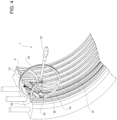
- figure 4 discloses a step of the extracting process wherein the upper half of the casing has been removed the winding wheel has been arranged on the casing at the seal and the pinching end 24 has been coupled to the seal.
- the user may drive the winding wheel along the seal that is progressively extracted winded in the winding wheel.
- the winding wheel is not driven and the lever returns in a correct and easy position for the user.
Landscapes
- Engineering & Computer Science (AREA)
- Mechanical Engineering (AREA)
- General Engineering & Computer Science (AREA)
- Turbine Rotor Nozzle Sealing (AREA)
- Sealing Using Fluids, Sealing Without Contact, And Removal Of Oil (AREA)
Abstract
Description
- The present invention relates to the technical field of the turbine power plant assembly. As known, in a turbine power plant assembly an incoming air flow is compressed by a compressor and mixed with an added fuel in a combustion chamber for producing a hot gas flow to be expanded in a turbine for generating a rotating work on a rotor in turn connected to a generator. The hot gas leaving the turbine in used in a turbine steam assembly wherein steam heated by the hot gas drives a steam turbine connected to a generator. In particular, the present invention relates to the field of the service for a turbine power plant assembly, i.e. the periodic inspection activities carried out in order to check the integrity of the components forming the assembly or the repairing activities carried out in order to repair components for restoring the assembly. More in detail, the service activity related to the present invention refers to operations to be performed for extracting a circumferential seal from its seat, in particular a labyrinth seal, in a turbine power plant assembly, in particular in the turbine steam assembly. In view of the above preliminary considerations related to the technical field of the present invention, the following description will refer to a portable device and to a method for extracting a circumferential seal from its seat, in particular a labyrinth seal, in a turbine power plant assembly by using this portable device.
- As known, a gas turbine assembly for power plants comprises a compressor assembly, a combustor assembly and a turbine assembly. The compressor assembly is configured for compressing incoming air supplied at a compressor inlet. The compressed air leaving the compressor assembly flows into a volume (called "plenum") and from there into the combustor assembly. This combustor assembly comprises usually a plurality of burners configured for injecting fuel (oil and/or gas fuel) in the compressed air flow. The mixture of fuel and compressed air enters a combustion chamber where this mixture is combusted. The resulting hot gas flow leaves the combustion chamber and drives in rotation the turbine assembly that performs a work on the rotor (in turn connected to a power generator). As known, the turbine assembly comprises a plurality of stages, or rows, of rotating blades that are interposed by a plurality of stages, or rows, of stator vanes. The rotating blades are supported by the rotor whereas the stator vanes are supported by a casing (called "vane carrier") that is concentric and surrounding the turbine assembly.
- In order to achieve a high efficiency, the hot gas flow has to disclose a very high turbine inlet temperature. However, in general this high temperature involves an undesired high NOx emission level. In order to reduce this emission and to increase operational flexibility without decreasing the efficiency, a so called "sequential" gas turbine is particularly suitable. In general, a sequential gas turbine comprises a first and a second combustor or a first and a second combustion stage wherein each combustor is provided with a plurality of burners and with at least a relative combustion chamber. Today at least two different kinds of sequential gas turbines are known. According to a first embodiment, the first and the second combustor are annular shaped and are physically separated by a stage of turbine blades, called high pressure turbine. Downstream the second combustor a second turbine unit is present (called low pressure turbine). According to a second embodiment of a sequential gas turbine, the gas turbine is not provided with the high pressure turbine and the combustor assembly is realized in form of a plurality of can-combustors arranged as a ring around the rotor. Each can-combustor comprises a first combustor and a second combustor arranged directly one downstream the other inside a common can shaped casing. These two example of gas turbine assemblies have been cited only as non-limiting examples wherein the present invention can be applied.
- The hot gas leaving the gas turbine in used in a steam turbine assembly wherein steam is heated by the hot gas and used for driving a steam turbine in turn connected to a generator.
- The present invention may be applied in any turbine power plant assembly (gas or steam systems) provided that at least a circumferential seal is present to be extracted from its seat.
- Substantially all turbine assemblies, in particular the steam turbines, are provided with circumferential seals, in particular labyrinth seals. A circumferential labyrinth seal is a seal made of a metallic material housed in a circumferential groove or seat obtained on the inner surface of the casing of the turbine casing. A circumferential labyrinth seal comprises an outer portion inside the casing groove and an inner portion protruding from the casing towards the turbine axis. This kind of seal is called "labyrinth seal" because the groove and the outer portion of the seal are configured to realize a leakage labyrinth path. As known, in a turbine power plant the seals are exposed in a very stressing ambient (very high temperature and pressure) and thus these seals need to be periodically removed for allowing the arrangement of new seals. The skilled person of this field well knows what a circumferential labyrinth seal is and thus additional details are not required for the correct understanding of the context of the present invention.
- The prior art practice for extracting the circumferential labyrinth seal from its seat requires the disassembly of the casing portion housing the seal for putting this assembly part in a separate extracting apparatus. Of course, after the extracting step, a new seal has to be housed in the seat and the removed casing portion has to be reassembled. As self-evident, this prior art involves the drawback of requiring the stop of the system and the moving of the system to the service point where the separate extracting apparatus is present.
- Thus, today there is the need to implement a new practice for extracting the circumferential labyrinth seal from its casing groove wherein the stop of the system is reduced and the extraction is performed in situ avoiding the need to put the casing portion in a separate extracting apparatus.
- Accordingly, a primary object of the present invention is to provide a portable device for extracting a circumferential labyrinth seal of a turbine power plant assembly (in particular a steam turbine), wherein this portable device is configured for being used onsite ("in-situ") in order to avoid the moving of the part of the system to a separate extracting apparatus. With the term "portable" we mean a device that can be used by hand by a user acting directly on the inner surface of the casing at the seal.
- Before entering into the mechanical details of the portable device, the present invention may also be defined as an alternative method for extracting a circumferential seal, in particular a labyrinth seal, in a turbine power plant assembly. Indeed, the prior art practice does not suggest to perform this extracting step by onsite. Therefore, the present invention also provides a method for extracting a circumferential seal, in particular a labyrinth seal, from its casing seat in a turbine power plant assembly, wherein the method comprises the steps of:
- a) providing a portable device that (as will be described in the following) comprises a winding wheel supporting a pinching device (as pliers) and a handle for moving the winding wheel;
- b) putting in contact the winding wheel with the inner surface of the casing where the circumferential seal is present;
- c) pinching the seal to be extracted with the pinching device;
- c) rolling the winding wheel on the casing along the seal by acting on the handle so that the seal is progressively extracted and winded on the winding wheel.
- Thus, the invention involves a reliable and efficient method performed by using a handly (portable and able to be used directly in contact with the casing) extracting device for extracting the circumferential, preferably labyrinth, seal. Please be noted that a traditional extracting process of this seal requires the disassembly of part of the casing of the turbine for putting the removed casing in a separate extracting station. On the contrary, according to the present invention the circumferential seal is extracted onsite by using a handly portable device moved by a user.
- As foregoing cited, the Applicant developed a new portable device suitable for performing the method of the invention, i.e. a portable device suitable for extracting a circumferential seal from its seat or grove obtained in a casing of a turbine power plant assembly. Therefore, the portable device according to the main definition of the invention comprises:
- a winding wheel configured to match (i.e. to go in contact) and to roll on the inner surface of the casing along the seal to be extracted;
- a pinching device supported by the winding wheel configured to pinch the seal to be extracted so that during the rolling of the winding wheel the seal is progressively extracted and winded in the winding wheel;
- a handle configured for being maneuvered by a user for moving, i.e. rolling, the winding wheel along the seal to be extracted.
- Preferably, the pinching device is realized in form of pliers having its pinching end at the edge or periphery of the winding wheel so that the seal can be pinched when the winding wheel is in contact to the casing.
- Preferably, the winding wheel defines a U shaped seat for progressively housing the seal during the extraction step. The seat has a window for allowing the pinching end of the pliers to couple with the seal to be extracted.
- Preferably, the handle is a lever having a first end coupled to the winding wheel at the center of the winding wheel.
- Preferably, the coupling between the lever and the wheel is configured so that acting on the lever along a first rotation direction the winding wheel is driven along the seal that is progressively extracted and acting on the lever along a second rotation direction the winding wheel is not driven along the seal.
- It is to be understood that both the foregoing general description and the following detailed description are exemplary, and are intended to provide further explanation of the invention as claimed. Other advantages and features of the invention will be apparent from the following description, drawings and claims.
- The features of the invention believed to be novel are set forth with particularity in the appended claims.
- Further benefits and advantages of the present invention will become apparent after a careful reading of the detailed description with appropriate reference to the accompanying drawings.
- The invention itself, however, may be best understood by reference to the following detailed description of the invention, which describes an exemplary embodiment of the invention, taken in conjunction with the accompanying drawings, in which:
-
figure 1 is a schematic view of a turbine assembly for power plants; -
figure 2 is a schematic view of a circumferential seal housed in a casing groove; -
figure 3 is a first view of an example of a portable device according to the present invention; -
figure 4 is a second view of the portable device offigure 3 disclosing the a step of the extracting process of the seal. - In cooperation with attached drawings, the technical contents and detailed description of the present invention are described thereinafter according to preferred embodiments, being not used to limit its executing scope. Any equivalent variation and modification made according to appended claims is all covered by the claims claimed by the present invention.
- Reference will now be made to the drawing figures to describe the present invention in detail. In particular, reference is made to
figure 1 which is a schematic view of a power plant turbine assembly that may be improved by the present invention. In general, no particular feature is required for providing a turbine power plant assembly suitable to be improved by the present invention. Generally, a turbine assembly is an assembly 1 as comprising: - a
compressor 2 for compressing air; - a
combustion chamber 3 for generating a hot gas flow having a main direction M; - a
turbine 4 driven by the hot gas flow for rotating arotor 5; - a generator for converting the rotating work of the
rotor 5. - The hot gas M leaving the
gas turbine 4 in fed to anheat exchanger 6 wherein, starting from water coming asource 14, steam is generated for driving asteam turbine 13 in turn connected to agenerator 15. -
Figure 2 is a schematic view of aseal 10 housed in a casing groove, in particular the casing of thesteam turbine 13. Thus,figure 2 discloses a portion of aturbine casing 7 comprising aninner surface 8 wherein acircumferential groove 9 has been obtained. Infigure 2 the references with arrows C and A refers to the axial direction A and to the circumferential direction C. These directions, and the third radial direction, are well known by the skilled person in the art. Inside the groove 9 aseal 10 is arranged. As disclosed, theseal 10 comprises aninner portion 11 constrained into thegroove 9 and anouter portion 12 protruding from the casing. The shape of thegroove 9 and the shape of theseal 10 disclosed infigure 2 are only not limiting examples. Preferably, the shape of thegroove 9 and the shape of theinner portion 11 are configured for realizing a leakage labyrinth path and thus the seal may be a labyrinth seal. -
Figure 3 is a first view of an example of aportable device 20 according to the present invention. The scope of thisdevice 20 is to handly extract theseal 10 onsite avoiding the presence of separated extracting apparatus. As disclosed infigure 3 , theportable device 20 comprises: - a winding
wheel 21 configured to roll on the on theinner surface 8 of thecasing 7 along theseal 10 to be extracted; - a pinching
device 22 supported by the windingwheel 21 configured to pinch theseal 10 to be extracted so that during the rolling of the windingwheel 21 theseal 10 is progressively extracted and winded in the windingwheel 21; - a
handle 23 configured for being maneuvered by a user for rolling the windingwheel 21 along theseal 10 to be extracted. - According to the example of
figure 3 , the pinchingdevice 22 is realized in form of pliers having its pinchingend 24 at the periphery of the windingwheel 21 so that the pinchingdevice 22 can pinch theseal 10 when the winding wheel is in contact to theinner surface 8 of thecasing 7. Ad disclosed infigure 4 , the periphery of the windingwheel 21 defines a U shapedseat 25 for progressively housing the seal in a winded configuration during the extraction step. Thehandle 23 offigure 3 is a lever parallel to the windingwheel 21 having afirst end 26 coupled to the windingwheel 21 at the center of the windingwheel 21. As represented infigure 3 , the coupling between thelever 23 and the windingwheel 21 is configured so that acting on thelever 23 along a first rotation direction R the windingwheel 21 is driven in rotation D along theseal 10 whereas acting on thelever 23 along a second rotation direction R' the windingwheel 21 is not driven along theseal 10. - Finally,
figure 4 discloses a step of the extracting process wherein the upper half of the casing has been removed the winding wheel has been arranged on the casing at the seal and the pinchingend 24 has been coupled to the seal. Starting from this configuration by acting on the lever the user may drive the winding wheel along the seal that is progressively extracted winded in the winding wheel. By acting on the lever along the opposite rotation direction, the winding wheel is not driven and the lever returns in a correct and easy position for the user. - Although the invention has been explained in relation to its preferred embodiment(s) as mentioned above, it is to be understood that many other possible modifications and variations can be made without departing from the scope of the present invention. It is, therefore, contemplated that the appended claim or claims will cover such modifications and variations that fall within the true scope of the invention.
Claims (7)
- A method for extracting a circumferential seal (10) from its seat (9), in particular a labyrinth seal, obtained in a casing (7) of a turbine power plant assembly (1); wherein the method comprises the steps of:a) providing a portable device (20) that comprises a winding wheel (21) supporting a pinching device (22) and a handle (23) for moving the winding wheel (21);b) putting in contact the winding wheel (21) with the inner surface (8) of the casing (7) where the circumferential seal (10) is present;c) pinching the seal (10) to be extracted with the pinching device (22);d) rolling the winding wheel (21) on the casing (7) along the seal (10) by acting on the handle (23) so that the seal (10) is progressively extracted and winded on the winding wheel (21).
- A portable device (20) for extracting a circumferential seal (10) from its seat (9) obtained on an inner surface (8) of a casing (7) of a turbine power plant assembly (1); wherein the portable device comprises:- a winding wheel (21) configured to roll on the on the inner surface (8) of the casing (7) along the seal (10) to be extracted;- a pinching device (22) supported by the winding wheel (21) configured to pinch the seal (10) to be extracted so that during the rolling of the winding wheel (21) the seal (10) is progressively extracted and winded in the winding wheel (21) ;- a handle (23) configured for being maneuvered by a user for rolling the winding wheel (21) along the seal (10) to be extracted.
- Device as claimed in claim 2, wherein the pinching device (22) is realized in form of pliers having its pinching end (24) at the periphery of the winding wheel (21) so that the pinching device (22) can pinch the seal (10) when the winding wheel (21) is in contact to the casing (7).
- Device as claimed in any one of the foregoing claims, wherein the periphery of the winding wheel (21) defines a U shaped seat (25) for progressively housing the seal (10) during the extraction step.
- Device as claimed in any one of the foregoing claims, wherein the handle (23) is a lever having a first end (26) coupled to the winding wheel (21) at the center of the winding wheel (21).
- Device as claimed in claim 5, wherein the lever (23) is parallel to the winding wheel (21).
- Device as claimed in claim 5 or 6, wherein the coupling between the lever (23) and the winding wheel (21) is configured so that acting on the lever (23) along a first rotation direction (R) the winding wheel (21) is driven (D) along the seal (10) and acting on the lever (23) along a second rotation direction (R') the winding wheel (21) is not driven along the seal (10).
Priority Applications (2)
| Application Number | Priority Date | Filing Date | Title |
|---|---|---|---|
| EP22425060.5A EP4390057A1 (en) | 2022-12-22 | 2022-12-22 | Portable device and method for extracting a circumferential seal from its seat, in particular a labyrinth seal, in a turbine power plant assembly |
| CN202311768527.4A CN118242153A (en) | 2022-12-22 | 2023-12-21 | Portable device and method for extracting a circumferential seal, in particular a labyrinth seal, from its seat in a turbine power plant assembly |
Applications Claiming Priority (1)
| Application Number | Priority Date | Filing Date | Title |
|---|---|---|---|
| EP22425060.5A EP4390057A1 (en) | 2022-12-22 | 2022-12-22 | Portable device and method for extracting a circumferential seal from its seat, in particular a labyrinth seal, in a turbine power plant assembly |
Publications (1)
| Publication Number | Publication Date |
|---|---|
| EP4390057A1 true EP4390057A1 (en) | 2024-06-26 |
Family
ID=85122698
Family Applications (1)
| Application Number | Title | Priority Date | Filing Date |
|---|---|---|---|
| EP22425060.5A Pending EP4390057A1 (en) | 2022-12-22 | 2022-12-22 | Portable device and method for extracting a circumferential seal from its seat, in particular a labyrinth seal, in a turbine power plant assembly |
Country Status (2)
| Country | Link |
|---|---|
| EP (1) | EP4390057A1 (en) |
| CN (1) | CN118242153A (en) |
Citations (3)
| Publication number | Priority date | Publication date | Assignee | Title |
|---|---|---|---|---|
| DE857330C (en) * | 1951-05-06 | 1952-11-27 | Kupfer Asbest Co | Device for removing shaft seals |
| DE102006052508A1 (en) * | 2006-11-06 | 2008-05-08 | Airbus Deutschland Gmbh | Device for removing sealing material and method |
| EP2853351B1 (en) * | 2013-09-27 | 2019-12-25 | Aktiebolaget SKF | Rotative assembly, method for dismounting a sealing element and extraction tool for dismounting a sealing element |
-
2022
- 2022-12-22 EP EP22425060.5A patent/EP4390057A1/en active Pending
-
2023
- 2023-12-21 CN CN202311768527.4A patent/CN118242153A/en active Pending
Patent Citations (3)
| Publication number | Priority date | Publication date | Assignee | Title |
|---|---|---|---|---|
| DE857330C (en) * | 1951-05-06 | 1952-11-27 | Kupfer Asbest Co | Device for removing shaft seals |
| DE102006052508A1 (en) * | 2006-11-06 | 2008-05-08 | Airbus Deutschland Gmbh | Device for removing sealing material and method |
| EP2853351B1 (en) * | 2013-09-27 | 2019-12-25 | Aktiebolaget SKF | Rotative assembly, method for dismounting a sealing element and extraction tool for dismounting a sealing element |
Also Published As
| Publication number | Publication date |
|---|---|
| CN118242153A (en) | 2024-06-25 |
Similar Documents
| Publication | Publication Date | Title |
|---|---|---|
| US7430802B2 (en) | Labyrinth seal in a stationary gas turbine | |
| US10844750B2 (en) | Method of disassembling and assembling gas turbine and gas turbine assembled thereby | |
| CN110185501B (en) | Gas turbine engine with guide vanes having cooling inlets | |
| US9567864B2 (en) | Centrifugal impeller and turbomachine | |
| US20100000219A1 (en) | Systems and Methods for Supplying Cooling Air to a Gas Turbine | |
| EP3208418B1 (en) | System for repairing a bend in a turbine blade | |
| JP2009243312A (en) | Cover for cooling passage, method of manufacturing the cover, and gas turbine | |
| US10215044B2 (en) | Interstage seal housing optimization system in a gas turbine engine | |
| US9169737B2 (en) | Gas turbine engine rotor seal | |
| US20150050135A1 (en) | Stator blade diaphragm ring, steam turbine and method | |
| US10808609B2 (en) | Method of assembling and disassembling gas turbine and gas turbine assembled thereby | |
| EP3450851A1 (en) | Transition duct for a gas turbine can combustor and gas turbine comprising such a transition duct | |
| EP4390057A1 (en) | Portable device and method for extracting a circumferential seal from its seat, in particular a labyrinth seal, in a turbine power plant assembly | |
| US5746573A (en) | Vane segment compliant seal assembly | |
| US20180058232A1 (en) | Segment for Sealing Device, and Turbine Rotor and Turbine Comprising Same | |
| CN110382869B (en) | Turbine pump | |
| EP3342979B1 (en) | Gas turbine comprising cooled rotor disks | |
| EP4390058B1 (en) | Portable device and method for milling a circumferential brush seal of a gas turbine assembly | |
| KR20190001906A (en) | Method of disassembling and assembling a gas turbine and a gas turbine assembled thereby | |
| EP4174286A1 (en) | Gas turbine assembly for power plant with improved rotor and turbine blades cooling and method for operating this gas turbine assembly | |
| EP4198265A1 (en) | Vane for a gas turbine assembly for power plant and gas turbine assembly for power plant comprising such a vane | |
| KR102566946B1 (en) | Sealing assembly and turbo-machine comprising the same | |
| CN102080574A (en) | Rotor assembly for a reheat steam turbine | |
| US20200141272A1 (en) | Intercooled tangential air injector for gas turbine engines |
Legal Events
| Date | Code | Title | Description |
|---|---|---|---|
| PUAI | Public reference made under article 153(3) epc to a published international application that has entered the european phase |
Free format text: ORIGINAL CODE: 0009012 |
|
| STAA | Information on the status of an ep patent application or granted ep patent |
Free format text: STATUS: THE APPLICATION HAS BEEN PUBLISHED |
|
| AK | Designated contracting states |
Kind code of ref document: A1 Designated state(s): AL AT BE BG CH CY CZ DE DK EE ES FI FR GB GR HR HU IE IS IT LI LT LU LV MC ME MK MT NL NO PL PT RO RS SE SI SK SM TR |
|
| STAA | Information on the status of an ep patent application or granted ep patent |
Free format text: STATUS: REQUEST FOR EXAMINATION WAS MADE |
|
| 17P | Request for examination filed |
Effective date: 20241204 |
|
| RBV | Designated contracting states (corrected) |
Designated state(s): AL AT BE BG CH CY CZ DE DK EE ES FI FR GB GR HR HU IE IS IT LI LT LU LV MC ME MK MT NL NO PL PT RO RS SE SI SK SM TR |
|
| RIC1 | Information provided on ipc code assigned before grant |
Ipc: F01D 5/00 20060101AFI20251125BHEP Ipc: B25B 27/00 20060101ALI20251125BHEP Ipc: F01D 11/00 20060101ALI20251125BHEP |
|
| GRAP | Despatch of communication of intention to grant a patent |
Free format text: ORIGINAL CODE: EPIDOSNIGR1 |
|
| STAA | Information on the status of an ep patent application or granted ep patent |
Free format text: STATUS: GRANT OF PATENT IS INTENDED |
|
| INTG | Intention to grant announced |
Effective date: 20260206 |