EP4390056A1 - Closed-chamber well testing - Google Patents
Closed-chamber well testing Download PDFInfo
- Publication number
- EP4390056A1 EP4390056A1 EP22306962.6A EP22306962A EP4390056A1 EP 4390056 A1 EP4390056 A1 EP 4390056A1 EP 22306962 A EP22306962 A EP 22306962A EP 4390056 A1 EP4390056 A1 EP 4390056A1
- Authority
- EP
- European Patent Office
- Prior art keywords
- fluid
- downhole
- operable
- sensors
- chamber
- Prior art date
- Legal status (The legal status is an assumption and is not a legal conclusion. Google has not performed a legal analysis and makes no representation as to the accuracy of the status listed.)
- Granted
Links
Images


Classifications
-
- E—FIXED CONSTRUCTIONS
- E21—EARTH OR ROCK DRILLING; MINING
- E21B—EARTH OR ROCK DRILLING; OBTAINING OIL, GAS, WATER, SOLUBLE OR MELTABLE MATERIALS OR A SLURRY OF MINERALS FROM WELLS
- E21B47/00—Survey of boreholes or wells
- E21B47/12—Means for transmitting measuring-signals or control signals from the well to the surface, or from the surface to the well, e.g. for logging while drilling
- E21B47/14—Means for transmitting measuring-signals or control signals from the well to the surface, or from the surface to the well, e.g. for logging while drilling using acoustic waves
-
- E—FIXED CONSTRUCTIONS
- E21—EARTH OR ROCK DRILLING; MINING
- E21B—EARTH OR ROCK DRILLING; OBTAINING OIL, GAS, WATER, SOLUBLE OR MELTABLE MATERIALS OR A SLURRY OF MINERALS FROM WELLS
- E21B33/00—Sealing or packing boreholes or wells
- E21B33/10—Sealing or packing boreholes or wells in the borehole
- E21B33/12—Packers; Plugs
- E21B33/124—Units with longitudinally-spaced plugs for isolating the intermediate space
-
- E—FIXED CONSTRUCTIONS
- E21—EARTH OR ROCK DRILLING; MINING
- E21B—EARTH OR ROCK DRILLING; OBTAINING OIL, GAS, WATER, SOLUBLE OR MELTABLE MATERIALS OR A SLURRY OF MINERALS FROM WELLS
- E21B47/00—Survey of boreholes or wells
- E21B47/12—Means for transmitting measuring-signals or control signals from the well to the surface, or from the surface to the well, e.g. for logging while drilling
-
- E—FIXED CONSTRUCTIONS
- E21—EARTH OR ROCK DRILLING; MINING
- E21B—EARTH OR ROCK DRILLING; OBTAINING OIL, GAS, WATER, SOLUBLE OR MELTABLE MATERIALS OR A SLURRY OF MINERALS FROM WELLS
- E21B49/00—Testing the nature of borehole walls; Formation testing; Methods or apparatus for obtaining samples of soil or well fluids, specially adapted to earth drilling or wells
- E21B49/08—Obtaining fluid samples or testing fluids, in boreholes or wells
- E21B49/087—Well testing, e.g. testing for reservoir productivity or formation parameters
Definitions
- Wells are constructed at Earth's surface or ocean bed and through subterranean geological formations to facilitate recovery of natural deposits of oil and/or gas trapped therein.
- Well construction operations include drilling a wellbore at a wellsite surface and through a subterranean geological formation comprising a subterranean reservoir containing reservoir fluid comprising oil and/or gas.
- a casing may be inserted therein and secured via cement, such as to protect a sidewall of the wellbore, isolate different subterranean formations through which the wellbore extends, and maintain control of the reservoir fluid and well pressure during various subsequent downhole operations.
- additional metal tubular strings may be inserted within the wellbore to facilitate production of the reservoir fluid to the wellsite surface.
- various well tests and intervention operations may be performed to evaluate and optimize well productivity.
- a well test includes measuring downhole pressure and flow rate of reservoir fluid to determine properties of a subterranean reservoir containing the reservoir fluid. Pressure and flow rate data recorded during the well test may then be analyzed to evaluate the subterranean reservoir, such as to predict well productivity.
- a well test can be used to identify various properties of a subterranean reservoir, including skin, effective permeability, and geology and connectivity of boundary systems around the wellbore.
- a well test can be carried out before or after a well is completed, and at different stages in the life of a subterranean reservoir.
- well tests come in a variety of sizes and modes of operation. Based on the duration and cost, well test modes can range from open-hole wireline testing, to slickline bottomhole pressure surveys of production wells, to simply monitoring shut-in wellhead pressure.
- a pressure disturbance generated in a subterranean reservoir is recorded by a downhole pressure sensor to determine bottomhole pressure (BHP) or by a surface pressure sensor to determine well head pressure (WHP).
- BHP bottomhole pressure
- HTP well head pressure
- Producing the reservoir fluid during a drawdown mode of a well test and shutting in the reservoir fluid during a build-up mode of the well test cause pressure disturbances at the wellsite surface, which are measured by pressure sensors of surface well test equipment.
- a standard well test includes a clean-up mode, an initial build-up mode, a flow mode (or drawdown), and a final build-up mode.
- the clean-up mode includes a first draw down to clean wellbore fluid (e.g., drilling fluid, completion fluid, etc.
- the flow mode includes opening the wellbore at a constant rate to permit the reservoir fluid to flow, thereby causing a decrease in the BHP.
- the build-up modes include shutting in the wellbore to prevent the reservoir fluid from flowing, causing an increase in the BHP.
- Pressure and flow rate data recorded during the well test can be analyzed to determine information about the well and the subterranean reservoir, including a well description for the tested well interval, such as a production index (PI) and skin, and a reservoir description, such as average/effective permeability, heterogeneities (e.g., fractures, layering, properties, etc. ) , boundaries, shape, distance, average pressure, and initial pressure.
- PI production index
- a reservoir description such as average/effective permeability, heterogeneities (e.g., fractures, layering, properties, etc. ) , boundaries, shape, distance, average pressure, and initial pressure.
- a downhole tubular string such as a drillstem testing (DST) string.
- the surface equipment may include a three-phase test separator and a surge tank choke manifold, which is used to control flow of the produced reservoir fluid.
- the tubular string may be used in conjunction with multiple packers and valve devices.
- operating such downhole equipment using pressure and string rotations can be very limiting and complicated.
- Operating such downhole equipment wirelessly by sending control commands in a sequential mode is time consuming and inefficient.
- the produced fluids can be connected to the production line and facilities. At locations that cannot accommodate storage and/or transport of produced reservoir fluid, the reservoir fluid has to be routed to a burner for disposal, resulting in a high carbon footprint.
- flaring of produced hydrocarbons is prohibited due to costs or environmental constraints.
- the present disclosure introduces a system including: a tubular string disposed within a wellbore; fluid control devices disposed in association with the tubular string and operable to form a downhole chamber configured to receive reservoir fluid from a subterranean reservoir; sensors disposed within the wellbore and operable to output sensor data indicative of properties of the reservoir fluid; wireless communication devices disposed within the wellbore and operable to communicate with each other, the fluid control devices, and the sensors; and a controller disposed at a wellsite surface.
- the controller is operable to output a multiple query string for transmission to the fluid control devices and/or the sensors via the wireless communication devices.
- the multiple query string includes queries each addressed to a corresponding instance of the fluid control devices and/or the sensors.
- the queries are operable to cause the corresponding fluid control devices and/or sensors to collectively perform at least a portion of a closed-chamber well test for determining properties of the subterranean reservoir.
- the present disclosure also introduces a system including: a tubular string disposed within a wellbore; fluid control devices disposed in association with the tubular string and operable to form a downhole chamber configured to receive reservoir fluid from a subterranean reservoir; sensors disposed within the wellbore and operable to output sensor data indicative of properties of the reservoir fluid; acoustic communication devices disposed within the wellbore and operable to communicate with each other, the fluid control devices, and the sensors; and a controller disposed at a wellsite surface.
- the controller is operable to output a multiple query string for transmission to the fluid control devices and/or the sensors via the acoustic communication devices.
- the multiple query string includes queries each addressed to a corresponding instance of: the fluid control devices; and/or the sensors.
- the queries are operable to cause the corresponding fluid control devices and/or sensors to collectively perform at least a portion of a closed-chamber well test for determining properties of the subterranean reservoir.
- Each acoustic communication device is operable to: transmit an instance of the queries to the corresponding fluid control device and/or sensor; receive response data output by the corresponding fluid control device and/or sensor; save the response data to the multiple query string; and transmit the multiple query string to a subsequent instance of the acoustic communication devices.
- the present disclosure also introduces a method that includes causing a surface controller to output a multiple query string to downhole fluid control devices and/or downhole sensors via wireless communication devices disposed in association with a downhole tubular string.
- the multiple query string includes queries each addressed to a corresponding instance of the downhole fluid control devices and/or the downhole sensors.
- the queries cause the corresponding downhole fluid control devices and/or downhole sensors to collectively perform at least a portion of a closed-chamber well test for determining properties of a subterranean reservoir.
- first and second features are formed in direct contact
- additional features may be formed interposing the first and second features, such that the first and second features may not be in direct contact.
- terms, such as upper, upward, above, lower, downward, and/or below are utilized herein to indicate relative positions and/or directions between apparatuses, tools, components, parts, portions, members and/or other elements described herein, as shown in the corresponding figures. Such terms do not necessarily indicate relative positions and/or directions when actually implemented. Such terms, however, may indicate relative positions and/or directions with respect to a wellbore when an apparatus according to one or more aspects of the present disclosure is utilized or otherwise disposed within the wellbore.
- the terms upper and upward may mean in the uphole direction
- the terms lower and downward may mean in the downhole direction.
- the present disclosure is directed to systems ( e.g., apparatus) and methods (e.g., processes, operations, etc. ) for performing a well test for evaluating a subterranean reservoir containing a reservoir fluid and predicting well productivity.
- An example system may facilitate a downhole chamber for containing a reservoir fluid produced during a well test and facilitate disposal of the produced reservoir fluid within a subterranean formation ( e.g ., this can prevent producing fluids and avoid handling and flaring such fluids at surface).
- Such system may further facilitate fluid communication between a subterranean reservoir containing the reservoir fluid and the chamber.
- a system within the scope of the present disclosure may utilize wireless telemetry to facilitate communication between surface equipment located at a wellsite surface and downhole equipment located within a well. Such system may also utilize the wireless telemetry to facilitate operational control of the downhole equipment (e.g ., valve actuation) and downhole data acquisition.
- a system within the scope of the present disclosure may be automated or otherwise operate automatically.
- a system within the scope of the present disclosure may facilitate automation schemes for controlling operation of the downhole equipment to thereby facilitate modes of operation of the well test.
- a system within the scope of the present disclosure may utilize an acoustic telemetry system to facilitate an automated, downhole, closed-chamber well test.
- a system within the scope of the present disclosure may facilitate parallel control (e.g ., automation) of the downhole equipment.
- a system within the scope of the present disclosure may use acoustic telemetry to actuate multiple pieces of downhole equipment with a single acoustic transmission.
- Such system may use real-time telemetry data above and below an isolation packer to facilitate real-time monitoring of operational status of the downhole equipment, thereby providing assurance of equipment/process integrity before proceeding with a subsequent mode (or sequence) of the well test.
- Such system may facilitate safe, step-by-step performance of the well test and ensure that the well test objectives and zonal isolation are met, such that individual reservoir evaluation integrity can be determined.
- a system within the scope of the present disclosure may save capital expenditures by eliminating or reducing the use of surface equipment for storing, moving, and/or otherwise handling the reservoir fluid produced during the well test. Such system may reduce the complexity and cost of the well test.
- a system within the scope of the present disclosure may eliminate the use of flaring of produced reservoir fluid, thereby reducing carbon emissions.
- a system within the scope of the present disclosure may reduce other environmental risks (e.g., oil spills) and exposure of wellsite personnel to health and safety hazards.
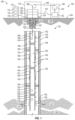
- FIG. 1 is a schematic view of at least a portion of an example implementation of a wellsite system 100 representing an example environment in which one or more aspects of the present disclosure may be implemented.
- the wellsite system 100 is depicted in relation to a wellbore 102 formed by rotary and/or directional drilling and extending from a wellsite surface 104 into a subterranean formation 106 comprising a subterranean reservoir 107 containing a reservoir fluid comprising oil and/or gas.
- the wellsite system 100 includes surface equipment 120 located at the wellsite surface 104 and downhole equipment 122 installed or otherwise disposed within the wellbore 102.
- the wellsite system 100 may be utilized to facilitate recovery of reservoir fluid containing the oil and/or gas via the wellbore 102. It is noted that although the wellsite system 100 is depicted as an onshore implementation, it is to be understood that the aspects described below are also generally applicable or readily adaptable to offshore implementations.
- the surface equipment 120 may comprise a well construction system 124, such as a well construction (e.g ., drilling) rig and associated well construction equipment.
- the well construction system 124 may comprise a mast, a derrick, and/or other support structure for supporting a drill string (not shown) for drilling the wellbore 102.
- the well construction system 124 may further comprise a driver (not shown), such as a top drive, operable to connect with an upper end of the drill string, and to impart rotary motion and vertical motion to the drill string.
- the top drive and the connected drill string may be suspended from the support structure via hoisting equipment (not shown), which may include a traveling block, a crown block, and a drawworks storing a support cable or line. The drawworks may thus selectively impart tension to the support line to lift and lower the top drive, resulting in the vertical motion of the drill string.
- the well construction system 124 may be operable to assemble the drill string at the wellsite surface 104 and install (or insert) the drill string within the wellbore 102 as the drill string is assembled.
- the drill string may comprise a plurality of drill pipes coupled together and terminating with a drill bit.
- the drill string may be inserted into the wellbore 102 through various fluid control equipment 126 disposed at the wellsite surface 104 over an opening of the wellbore 102.
- the fluid control equipment 126 may be operable to control fluid within the wellbore 102 during the well construction ( e.g ., drilling) operations.
- the fluid control equipment 126 may include fluid control valves, spools, and fittings individually and/or collectively operable to direct and/or otherwise control the flow of wellbore fluid (e.g., drilling fluid and/or reservoir fluid) out of the wellbore 102.
- the fluid control equipment 126 may also comprise a blowout preventer (BOP) stack operable to prevent the flow of the wellbore fluid out of the wellbore 102.
- BOP blowout preventer
- the fluid control equipment 126 may be mounted on top of a wellhead 128.
- the well construction system 124 may further include drilling fluid circulation equipment operable to circulate drilling fluid between the surface equipment 120 and the drill string during drilling and other operations.
- the drilling fluid circulation equipment may comprise a pit, a tank, and/or other fluid container holding the drilling fluid (i.e., drilling mud), and one or more mud pump units (i.e., drilling fluid pumps) operable to move the drilling fluid from the container into the drill string.
- the drilling fluid lubricates the drill bit and carries formation cuttings uphole to the wellsite surface 104.
- the returning drilling fluid may exit the wellbore via different fluid control equipment 126 during different stages or scenarios of well drilling operations.
- the drilling fluid returning to the wellsite surface 104 may be cleaned and/or reconditioned via the drilling fluid reconditioning equipment (not shown), which may include one or more of liquid-gas (i.e., mud gas) separators, shale shakers, and other drilling fluid cleaning and reconditioning equipment.
- the drilling fluid reconditioning equipment may include one or more of liquid-gas (i.e., mud gas) separators, shale shakers, and other drilling fluid cleaning and reconditioning equipment.
- the well construction system 124 may further include power tongs (e.g., an iron roughneck) (not shown) for making up and breaking out connections between each piece (or joint) of the drill string to assemble and disassemble the drill string.
- a set of slips may be located on the rig floor, such as may accommodate therethrough the drill string during tubular make-up and break-out operations and during drilling operations.
- the slips may be in an open position during drilling operations to permit advancement of the drill string, and in a closed position to clamp the upper end ( e.g., the uppermost tubular) of the drill string to thereby suspend and prevent advancement of the drill string within the wellbore 102, such as during the make-up and break-out operations.
- the various well construction equipment of the well construction system 100 may progress through a plurality of coordinated operations (i.e., operational sequences) to drill or otherwise construct the wellbore 102.
- the well construction system 124 (and other surface equipment 120) may be used to perform well completion operations to prepare the wellbore 102 for production.
- the well construction system 124 may be operable to install or otherwise dispose the downhole equipment 122 within the wellbore 102.
- the well construction system 124 may be operable to assemble the casing 108 at the wellsite surface 104, install (or insert or dispose) the casing 108 within the wellbore 102, and inject cement 109 between a sidewall of the wellbore 102 and the casing 108 to secure the casing 108 within the wellbore 102.
- the well construction system 124 may be further operable to assemble a tubular string 130 at the wellsite surface 104 and install (e.g ., insert or dispose) the tubular string 130 within the wellbore 102 as the tubular string 130 is assembled.
- the tubular string 130 may comprise a plurality of tubular members (e.g ., drill pipes, tough logging condition (TLC) pipes, drill collars, etc.).
- the tubular string 130 may comprise an inner surface defining an internal space (or bore) 103 of the tubular string 130.
- the tubular string 130 may further comprise an outer surface defining an annular space (or annulus) 105 between the outer surface of the tubular string 130 and an inner surface of the wellbore 102 ( i.e., an inner surface of the casing 108 lining the wellbore 102).
- the surface equipment 120 may further comprise a fluid delivery system 160 operable to inject or otherwise deliver a fluid downhole to a predetermined location or depth within the wellbore 102.
- the fluid delivery system 160 may thus be or comprise a fluid source.
- the fluid delivery system 160 may comprise a fluid container 162 containing a fluid (e.g., a gas or a liquid).
- the fluid delivery system 160 may also comprise a reel (or drum) 164 configured to store thereon a wound length of a fluid conduit 166 (e.g., coiled tubing) for delivering the fluid into the wellbore 102.
- the fluid delivery system 160 may further comprise a conveyance device 168 operable to apply adjustable downward and/or upward forces to the fluid conduit 166 to convey the fluid conduit 166 within the wellbore 102.
- the conveyance device 168 may be, comprise, or form at least a portion of a sheave or pulley, a winch, a drawworks, an injector head, and/or other device operable to guide and/or move the fluid conduit 166 within the wellbore 102.
- the conveyance device 168 may be supported above the wellbore 102 via a mast, a derrick, a crane, and/or other support structure (not shown).
- the reel 164 may be selectively wound and unwound by the conveyance device 168 to selectively convey the fluid conduit 166 into, within, and out of the wellbore 102.
- the fluid delivery system 160 may also comprise a fluid conduit 167 for delivering the fluid into the wellbore 102 at the wellsite surface 104.
- the fluid conduit 167 may extend between the fluid container 162 and one or more of the wellhead 128 and the fluid control equipment 126 to fluidly connect the fluid container 162 and upper end of the wellbore 102.
- the fluid delivery system 160 may be or comprise a gas delivery system (or source) operable to inject a gas (e.g ., nitrogen) into the tubular string 130 downhole via the fluid conduit 166 or at the wellsite surface 104 via the fluid conduit 167.
- a gas e.g ., nitrogen
- the fluid delivery system 160 may instead be or comprise a liquid (or slurry) delivery system (or source) operable to inject a liquid (e.g., well kill fluid) into the tubular string 130 downhole via the fluid conduit 166 or at the wellsite surface 104 via the fluid conduit 167.
- a liquid e.g., well kill fluid
- the surface equipment 120 may further comprise a sealing and alignment assembly 129 mounted on the fluid control equipment 126 and operable to seal the fluid conduit 166 during downhole conveyance and operations.
- the sealing and alignment assembly 129 may comprise a lock chamber (e.g., a lubricator, an airlock, a riser, etc. ) mounted on the fluid control equipment 126 and a stuffing box operable to seal around the fluid conduit 166, although such details are not shown in FIG. 1 .
- the stuffing box may be operable to seal around an outer surface of the fluid conduit 166, for example via annular packings applied around the surface of the fluid conduit 166 and/or by injecting a fluid between the outer surfaces of the fluid conduit 166 and an inner wall of the stuffing box.
- the fluid conduit 166 may thus be deployed into and retrieved from the wellbore 102 via the conveyance device 168 through the wellhead 128, the fluid control equipment 126, and/or the sealing and alignment assembly 129.
- the downhole equipment 122 may further comprise a plurality of fluid control devices 132-144 and sensors 145-149 (and other devices) carried by, connected to, or otherwise disposed in association with a lower portion of the tubular string 130.
- the upper and longer portion of the tubular string 130 may be referred to as a major string and the lower and shorter portion of the tubular string 130 associated with the fluid control devices 132-144 and sensors 145-149 may be referred to as a bottomhole assembly (BHA).
- BHA bottomhole assembly
- the tubular string 130 may be referred to in the oil and gas industry as a tubular tool string or a drill stem.
- the fluid control devices 132-144 may comprise an upper sleeve device 132 and a lower sleeve device 134 for selectively controlling fluid flow between the internal space 103 and the annular space 105.
- the upper sleeve device 132 may comprise an upper sleeve selectively movable between a closed position in which the upper sleeve and, thus, the upper sleeve device 132 prevents flow of fluid between the internal space 103 and the annular space 105, and an open position in which the upper sleeve and, thus, the upper sleeve device 132 permits flow of fluid between the internal space 103 and the annular space 105.
- the lower sleeve device 134 may comprise a lower sleeve selectively movable between a closed position in which the lower sleeve and, thus, the lower sleeve device 134 prevents flow of fluid between the internal space 103 and the annular space 105, and an open position in which the lower sleeve and, thus, the lower sleeve device 134 permits flow of fluid between the internal space 103 and the annular space 105.
- the fluid control devices 132-144 may further comprise an upper valve device 136, a lower valve device 138, and an intermediate valve device 140 between the upper valve device 136 and the lower valve device 138.
- the valve devices 136, 138, 140 may be or comprise downhole tester valves. Each valve device 136, 138, 140 may be operable to selectively control fluid flow within (or along) the internal space 103.
- the upper valve device 136 may comprise a gate, a sleeve, a flapper, or other blocking member selectively movable between a closed position in which the blocking member and, thus, the upper valve device 136 prevents flow of fluid within the internal space 103, and an open position in which the blocking member and, thus, the upper valve device 136 permits flow of fluid within the internal space 103.
- the lower valve device 138 may comprise a gate, a sleeve, a flapper, or other blocking member selectively movable between a closed position in which the blocking member and, thus, the lower valve device 138 prevents flow of fluid within the internal space 103, and an open position in which the blocking member and, thus, the lower valve device 138 permits flow of fluid within the internal space 103.
- the intermediate valve device 140 may comprise a gate, a sleeve, a flapper, or other blocking member selectively movable between a closed position in which the blocking member and, thus, the intermediate valve device 140 prevents flow of fluid within the internal space 103, and an open position in which the blocking member and, thus, the intermediate valve device 140 permits flow of fluid within the internal space 103.
- the fluid control devices 132-144 may also comprise an upper packer 142 for selectively controlling fluid flow within the annular space 105 and a lower packer 144 for selectively controlling fluid flow within the annular space 105.
- the upper packer 142 may comprise a packer element selectively movable between a set (or expanded) position in which the packer element and, thus, the upper packer 142 is set against the inner surface of the casing 108 to seal the annular space 105 and prevent flow of fluid within the annular space 105, and an unset (or retracted) position in which the packer element and, thus, the upper packer 142 is unset from the inner surface of the casing 108 to unseal the annular space 105 and permit flow of fluid within the annular space 105.
- the lower packer 144 may comprise a packer element selectively movable between a set position in which the packer element and, thus, the lower packer 144 is set against the inner surface of the casing 108 to seal the annular space 105 and prevent flow of fluid within the annular space 105, and an unset position in which the packer element and, thus, the lower packer 144 is unset from the inner surface of the casing 108 to unseal the annular space 105 and permit flow of fluid within the annular space 105.
- the packers 142, 144 may be retrievable packers used to temporarily create a fluid barrier between the subterranean reservoir 107 and the annular space 105 between the packers 142, 144.
- the lower packer 144 may form a fluid barrier between the subterranean reservoir 107 and the downhole equipment 122 and annular space 105 above the lower packer 144.
- the upper packer 142 may seal the annular space 105 between the packers 142, 144.
- the lower packer 144 may be a rotation-to-set packer (i.e., a mechanical packer) and the upper packer 142 may be a non-rotation-to-set packer that can be wirelessly controlled ( e.g ., via acoustic telemetry).
- the downhole equipment 122 may further comprise a perforating gun 146 connected to or otherwise carried by the BHA of the tubular string 130.
- the perforating gun 146 may be selectively operable to perforate the well, including the casing 108, the cement 108, and the subterranean formation 106 surrounding the wellbore 102 to cause the reservoir fluid to be discharged from or otherwise flow out of the subterranean reservoir 107 into the wellbore 102, including the internal space 103 of the tubular string 130.
- the downhole equipment 122 may further comprise a choke (not shown) connected to or otherwise carried by the BHA of the tubular string 130 along the internal space 103 of the tubular string 130.
- the choke may be disposed adjacent to ( e.g., just above or below) the lower valve device 138.
- the choke may be selectively operable to vary ( e.g ., reduce) flow rate of the reservoir fluid flowing into or along the internal space 103 of the tubular string 130.
- the downhole equipment 122 may further comprise a fluid sampler (not shown) connected to or otherwise carried by the BHA of the tubular string 130 along the internal space 103 of the tubular string 130.
- the fluid sampler may be disposed adjacent to ( e.g., just above or below) the lower valve device 138.
- the fluid sampler may be selectively operable to take samples of the reservoir fluid flowing into or along the internal space 103 of the tubular string 130, analyze the reservoir fluid samples, and output sample data indicative of properties of the reservoir fluid sample.
- the fluid control devices 132-144, the sensors 145-149, the perforating gun 146, the choke, and/or the fluid sampler may each comprise a wireless communication device permitting the fluid control devices 132-144, the sensors 145-149, the perforating gun 146, the choke, and/or the fluid sampler to wirelessly communicate with other wireless communication devices disposed downhole and within a wireless communication range.
- the fluid control devices 132-144, the sensors 145-149, the perforating gun 146, the choke, and/or the fluid sampler may each be operable to wirelessly receive control data (e.g., control commands, information queries, etc.) operable to cause that instance of the fluid control devices 132-144, the sensors 145-149, the perforating gun 146, the choke, and/or the fluid sampler to perform a predetermined operation or otherwise operate in a predetermined manner.
- the fluid control devices 132-144, the sensors 145-149, the perforating gun 146, the choke, and/or the fluid sampler may each be operable to wirelessly transmit feedback data (e.g., sensor data, status data, etc.
- Each wireless communication device of the fluid control devices 132-144, the sensors 145-149, the perforating gun 146, the choke, and/or the fluid sampler may be or comprise an acoustic communication device operable to communicate with another downhole communication devices via acoustic signals, which may propagate or travel through or along the tubular string 130 and/or a fluid located within the wellbore 102, as indicated by arrows 151, 152.
- the fluid control devices 132-144 in conjunction with the tubular string 130, may be operable to form a downhole chamber 110 configured to receive the reservoir fluid discharged from the subterranean reservoir 107 into the wellbore 102.
- the chamber 110 may comprise the internal space 103 between the upper valve device 136 and the lower valve device 138, and the annular space 105 between the upper packer 142 and the lower packer 144.
- the reservoir fluid discharged from the subterranean reservoir 107 into the wellbore 102 may be directed to or received by the chamber 110.
- the chamber 110 may be configured to facilitate a closed-chamber well test for determining properties of the subterranean reservoir 107.
- the fluid control devices 132-144, the sensors 145-149, the choke, and/or the fluid sampler may be operable to collectively perform at least a portion of the closed-chamber well test, including a flow rate test and a pressure build-up test of the reservoir fluid discharged from the subterranean reservoir 107.
- the sensors 145-149 may be operable to output sensor data indicative of properties of the reservoir fluid discharged from the subterranean reservoir 107 into the chamber 110 and/or a portion of the wellbore 102 external from the chamber 110.
- the sensors 145-149 may comprise a flow rate sensor (or a flowmeter) operable to output flow rate data indicative of flow rate of the reservoir fluid flowing into the chamber 110 and/or a portion of the wellbore 102 external from the chamber 110.
- the sensors 145-149 may also or instead comprise a pressure sensor operable to output pressure data indicative of pressure of the reservoir fluid flowing into the chamber 110 and/or a portion of the wellbore 102 external from the chamber 110.
- the sensors 145-149 may also or instead comprise a temperature sensor operable to output temperature data indicative of temperature of the reservoir fluid flowing into the chamber 110 and/or a portion of the wellbore 102 external from the chamber 110.
- the properties of the subterranean reservoir 107 may then be determined based on sensor data output by the sensors 145-149 during the closed-chamber well test.
- the sensor data output by the sensors 145-149 may be further indicative of operational status of the certain downhole equipment, such as the packers 142, 144, the valve devices 136, 138, 140, and the sleeve devices 132, 134.
- the sensors 145 may be disposed above the upper valve device 136, the sensors 147 may be disposed between the upper valve device 136 and the lower valve device 138, and the sensors 149 may be disposed below the lower valve device 138.
- the sensors 145-149 may be set to acquire sensor data at predetermined acquisition (or sampling) rates (e.g., every one second, one minute, five minutes, etc. ) .
- Data acquisition software run by the sensors 145-149 may continue to query data with a fixed rate until the rate is changed for a specific reason, such as a well test phase change (e.g ., from a flow mode to a pressure build-up mode, wherein during the build-up more, specific acquisition rates are used).
- a well test phase change e.g ., from a flow mode to a pressure build-up mode, wherein during the build-up more, specific acquisition rates are used.
- Ability to have dynamic and adaptive acquisition rates during the well test may reduce energy usage and optimize battery life of the sensors 145-149 and other downhole equipment 122 in communication with the sensors 145-149.
- the downhole equipment 122 may further comprise a plurality of downhole wireless communication devices 150 disposed within the wellbore 102 and operable to communicate with each other, the fluid control devices 132-144, the sensors 145-149, the perforating gun 146, the choke, and/or the fluid sampler.
- the wireless communication devices 150 may be carried by, connected to, or otherwise disposed in association with the tubular string 130. For example, the wireless communication devices 150 may be clamped onto an outer surface of the tubular string 130.
- the wireless communication devices 150 disposed in association with the BHA portion of the tubular string 130 may be associated with the fluid control devices 132-144, the sensors 145-149, the perforating gun 146, the choke, and/or the fluid sampler.
- the surface equipment 120 may comprise a surface wireless communication device 154 carried by, connected to, or otherwise disposed in association with one or more of the wellhead 128 and the fluid control equipment 126.
- the wireless communication device 154 may be communicatively connected ( e.g., via wired or wireless communication means) with and operable to communicate with one or more of the surface equipment 120.
- the wireless communication device 154 may also be communicatively connected ( e.g ., via wireless communication means) with and operable to communicate with one or more of the downhole wireless communication devices 150.
- the wireless communication device 154 may thus facilitate communication between one or more of the surface equipment 120 and one or more of the downhole wireless communication devices 150.
- the wireless communication devices 150, 154 may each operable to communicate with another one or more of the wireless communication devices 150, 154, the fluid control devices 132-144, the sensors 145-149, the perforating gun 146, the choke, and/or the fluid sampler via wireless signals.
- the wireless communication devices 150, 154 may be or comprise acoustic repeaters (or modems), each operable to communicate with one or more of other wireless communication devices 150, 154, the fluid control devices 132-144, the sensors
- the wireless communication device 154 may be a master (or hub) wireless communication device operable to translate a digital control command (e.g., an algorithm) into a wireless signal, such as an acoustic signal.
- a digital control command e.g., an algorithm
- Acoustic communication may comprise generating an acoustic wave (or vibrations) at one location along the tubular string 130 and modulating the vibrations to code digital information into or within the vibrations.
- a transmission TX
- the acoustic wave the travels along the tubular string 130 to another location with a receiver.
- the receiver demodulates and decodes the received acoustic wave and transforms it back to digital information.
- reception RX
- acoustic transmission through a testing string or drilling pipe is complex. Attenuation of an acoustic wave strongly depends on frequency of the acoustic wave. Overall, it is difficult to propagate an acoustic wave across several tens of thousands of feet.
- each wireless communication device 150 of the network of wireless communication devices 150 forms a small footprint and uses low power and is operable to transmit and receive an acoustic wave. Each wireless communication device 150 can therefore process data within the acoustic wave and transmit it again with a higher amplitude (or power) to the next wireless communication device 150 along the tubular string 130.
- Each wireless communication device 150 may comprise an acoustic transducer and associated electronics, packaged in a single cartridge.
- Each wireless communication device 150 may be powered by a battery.
- the network of wireless communication devices 150 may facilitate real-time bidirectional communication (e.g., control, data acquisition, etc. ) between one or more of the surface equipment 120 and one or more of the downhole equipment 122.
- the surface equipment 120 may further comprise a power and control system 170 (e.g., a control center) may be utilized to monitor and control various portions of the wellsite system 100.
- the power and control system 170 may be located at the wellsite surface 104 or on a structure located at the wellsite surface 104. However, the power and control system 170 may instead be located at a location remote from the wellsite surface 104.
- the power and control system 170 may include a source of electrical power 172, a control workstation 174 (i.e., a human machine interface (HMI)), and a surface controller 176 (e.g., a processing device or computer).
- the electrical power source 172 e.g., a battery, an electric generator, etc.
- the surface controller 176 may supply electrical power to various surface and downhole equipment 120, 122 of the wellsite system 100, including the control workstation 174 and the surface controller 176.
- the surface controller 176 may be communicatively connected with various equipment of the wellsite system 100, such as may permit the surface controller 176 to monitor operations of one or more portions of the wellsite system 100 and/or to provide manual and/or automatic control of one or more portions of the wellsite system 100, including surface equipment 120, such as the fluid delivery system 160 and the surface wireless communication device 154, and the downhole equipment 122, such as the fluid control devices 132-144, the sensors 145-149, the perforating gun 146, the choke, the fluid sampler, and the wireless communication devices 150.
- the control workstation 174 may be communicatively connected with the surface controller 176 and may include input devices (e.g., a joystick, a keyboard, etc. ) for receiving the control data from human wellsite personnel and output devices (e.g., a video monitor, audio speakers, etc. ) for displaying sensor data and other information to the wellsite personnel.
- the surface controller 176 may be operable to receive and process downhole data (e.g ., sensor data) or information received from the downhole equipment 122 and/or control data ( i.e., control commands) entered to the surface controller 176 by the wellsite personnel via the control workstation 174.
- the surface controller 176 may store executable computer programs and/or instructions and may be operable to automatically implement or otherwise cause one or more aspects of methods, processes, and operations described herein based on the executable computer programs, the received sensor data, and the received control data.
- the control workstation 174 may also or instead be used by the wellsite personnel to manually control one or more portions of the wellsite system 100 to thereby implement or otherwise cause one or more aspects of methods, processes, and operations described herein.
- the network of wireless communication devices 150 may facilitate real-time bidirectional communication (e.g., control, data acquisition, etc. ) between the power and control system 170 (e.g., the surface controller 176) and one or more of the downhole equipment 122 to thereby facilitate real-time control of the downhole equipment 122 by the surface controller 176.
- the power and control system 170 may be used to cause the surface equipment 120 and the downhole equipment 122 to collectively perform at least a portion of the closed-chamber well test for determining properties of the subterranean reservoir 107.
- the wellsite personnel may use the control workstation 174 to manually control one or more of the surface equipment 120 and the downhole equipment 122 to cause the surface equipment 120 and the downhole equipment 122 to perform at least a portion of the closed-chamber well test.
- the wellsite personnel may instead use the control workstation 174 to manually initiate operation of the surface controller 176 to cause the surface controller 176 to automatically control one or more of the surface equipment 120 and the downhole equipment 122 to thereby cause the surface equipment 120 and the downhole equipment 122 to automatically perform at least a portion of the closed-chamber well test.
- the surface controller 176 may be operable to output control data to the fluid control devices 132-144, the sensors 145-149, the choke, and/or the fluid sampler via the wireless communication devices 150, 154 to thereby cause the fluid control devices 132-144, the sensors 145-149, the choke, and/or the fluid sampler to perform at least a portion of the closed-chamber well test.
- the surface controller 176 may output the control data to the surface wireless communication device 154, which may then wirelessly communicate the control data to one or more of the downhole wireless communication devices 150, which may receive and relay (or forward) the control data downhole, as indicated by the arrows 151, to the fluid control devices 132-144, the sensors 145-149, the choke, and/or the fluid sampler, thereby causing the fluid control devices 132-144, the sensors 145-149, the choke, and/or the fluid sampler to perform at least a portion of the closed-chamber well test.
- the control data output by the surface controller 176 to the fluid control devices 132-144, the sensors 145-149, the choke, and/or the fluid sampler may be output by the surface controller 176 and/or otherwise transmitted to the fluid control devices 132-144, the sensors 145-149, the choke, and/or the fluid sampler in the form of a plurality of multiple query strings, each comprising a plurality of queries ( e.g ., simple queries), each addressed or otherwise designated to a corresponding instance of the fluid control devices 132-144, the sensors 145-149, the choke, and/or the fluid sampler.
- queries e.g ., simple queries
- a query of a multiple query string may be or comprise a separate data batch operable to cause a corresponding instance of the fluid control devices 132-144, the sensors 145-149, the choke, and/or the fluid sampler to perform a predetermined operation or otherwise operate in a predetermined manner.
- the multiple query strings may instead be actually generated (or compiled) by the surface wireless communication device 154 based on control commands output by the surface controller 176.
- the surface wireless communication device 154 may thus be or form a portion of the surface controller 176 (or a surface control system) operable to cause the fluid control devices 132-144, the sensors 145-149, the choke, and/or the fluid sampler to perform at least a portion of the closed-chamber well test.
- Each multiple query string may be transmitted to the fluid control devices 132-144, the sensors 145-149, the choke, and/or the fluid sampler via the wireless communication devices 150, 154 to thereby cause the fluid control devices 132-144, the sensors 145-149, the choke, and/or the fluid sampler to perform at least a portion of the closed-chamber well test.
- Each multiple query string received or generated by the surface wireless communication device 154 may be wirelessly communicated by the surface wireless communication device 154 in the form of a wireless signal, as indicated by the arrows 151, to one or more of the downhole wireless communication devices 150.
- Each downhole wireless communication device 150 may receive a multiple query string and check if one or more of the queries contained therein are addressed to that downhole wireless communication device 150 (or an associated one of the fluid control devices 132-144, the sensors 145-149, the choke, or the fluid sampler). If yes, then the downhole wireless communication device 150 will dequeue the query, process the query, transmit the query to the associated one of the fluid control devices 132-144, the sensors 145-149, the choke, and the fluid sampler.
- the downhole wireless communication device 150 will relay the multiple query string downhole in the form of a wireless signal, as indicated by the arrows 151, to a subsequent wireless communication device 150, which may then check if one or more of the queries contained therein are addressed to that downhole wireless communication device 150 (or an associated one of the fluid control devices 132-144, the sensors 145-149, the choke, or the fluid sampler). Such process may continue until each query of the multiple query string is received by a downhole wireless communication device 150 (or an associated one of the fluid control devices 132-144, the sensors 145-149, the choke, or the fluid sampler).
- a multiple query string may be referred to as a multiple hop query, as the multiple query string is relayed (or hops) multiple times between the wireless communication devices 150, 154.
- a query of a multiple query string may be or comprise a control command addressed to a corresponding instance of the fluid control devices 132-144 and the choke.
- Each wireless communication device 150 may thus be operable to transmit an instance of the control commands to a corresponding instance of the fluid control devices 132-144 and the choke.
- Each control command may be operable to cause a corresponding instance of the fluid control devices 132-144 and the choke to perform a predetermined mechanical operation ( e.g ., open or close) or otherwise mechanically operate in a predetermined manner to perform at least a portion of the closed-chamber well test.
- the multiple query string may thus be or comprise a multiple control command string.
- a multiple query string may also or instead be or comprise a multiple sensor data string, wherein a query of a multiple query string may be or comprise a sensor data request addressed to a corresponding instance of the sensors 145-149 and the fluid sampler.
- Each wireless communication device 150 may thus be operable to transmit an instance of the sensor data requests to a corresponding instance of the sensors 145-149 and the fluid sampler.
- Each sensor data request may be operable to cause a corresponding instance of the sensors 145-149 and the fluid sampler to measure a property of the reservoir fluid to perform at least a portion of the closed-chamber well test.
- each of the fluid control devices 132-144, the sensors 145-149, the choke, and/or the fluid sampler may be operable to output and wirelessly transmit a response (or feedback) data to a corresponding wireless communication device 150.
- a response (or feedback) data may be operable to output and wirelessly transmit a confirmation data indicative that the predetermined operation indicated by the corresponding query has been performed.
- An instance of the sensors 145-149 and the fluid sampler may be operable to output and wirelessly transmit a corresponding sensor data indicative of the property of the reservoir fluid.
- the corresponding wireless communication device 150 may then receive the response data output by the corresponding instance of the fluid control devices 132-144, the sensors 145-149, the choke, and/or the fluid sampler, save the response data to the multiple query string (i.e., queue the response in the payload of the multiple query string), and transmit the multiple query string to a subsequent instance of the wireless communication devices 150.
- the subsequent instance of the wireless communication devices 150 may then transmit an instance of the queries to a corresponding instance of the fluid control devices 132-144, the sensors 145-149, the choke, and/or the fluid sampler, receive response data output by the corresponding instance of the fluid control devices 132-144, the sensors 145-149, the choke, and/or the fluid sampler, save the response data to the multiple query string, and transmit the multiple query string to another subsequent instance of the wireless communication devices 150. Such process may be repeated until a final (e.g ., most downhole) instance of the wireless communication devices 150 receives the multiple query string.
- the final instance of the wireless communication devices 150 may operable to compile the responses saved to the multiple query string and transmit the multiple query string to the surface controller 176 via the wireless communication devices 150, 154.
- the surface controller 176 may then receive the multiple query strings communicated during the closed-chamber well test, confirm operation of certain downhole equipment 122, and determine properties of the subterranean reservoir 107 based on the sensor data saved in the multiple query strings.
- the closed-chamber well test that can be performed by the fluid control devices 132-144, the sensors 145-149, the choke, and/or the fluid sampler may comprise a plurality of modes (i.e., stages or phases) of operation that may be performed to facilitate the sensor data based on which the properties of the subterranean reservoir 107 can be determined.
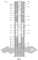
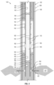
- FIGS. 2-6 show the downhole equipment 122 during different modes of operation of the closed-chamber well test.
- the fluid control devices 132-144 are selectively operable between open and closed positions.
- a closed position of a fluid control device 132-144 is indicated in FIGS. 2-6 by a rectangular box containing or otherwise encompassing crossed lines (in an X configuration).
- An open position of a fluid control device 132-144 is indicated in FIGS. 2-6 by a rectangular box that does not encompass crossed lines or is otherwise empty.
- FIG. 2 shows the downhole equipment 122 during a clean-up mode of operation of the closed-chamber well test during which the wellbore fluid located within the downhole chamber 110 may be evacuated or otherwise forced out of the chamber 110.
- the surface controller 176 and/or wellsite human personnel may operate the fluid delivery system 160 to cause the fluid conduit 166 to be deployed within the internal space 103 of the tubular string 130 until the fluid conduit 166 reaches the upper valve device 136 or extends below the upper valve device 136.
- the fluid delivery system 160 may be operable to inject a gas (e.g. , nitrogen) into the chamber 110 to force or otherwise displace the wellbore fluid out of the chamber 110.
- a gas e.g. , nitrogen
- the surface controller 176 may then initiate the clean-up mode by outputting a multiple query string to the surface wireless communication device 154, which may then wirelessly communicate the multiple query string to one or more of the downhole wireless communication devices 150, which may then wirelessly communicate the multiple query string to the fluid control devices 132-144.
- the queries of the multiple query string may cause the upper packer 142 to open to permit flow of the wellbore fluid upward out of the chamber 110, the upper sleeve device 132 to close to prevent flow of the gas and the wellbore fluid between the spaces 103, 105, the upper valve device 136 to open to permit flow of the gas downward into the chamber 110, the intermediate valve device 140 open to permit flow of the gas and the wellbore fluid, the lower sleeve device 134 to open to permit flow of the gas and the wellbore fluid between the spaces 103, 105, the lower packer 144 to close to prevent flow of the wellbore fluid upward into the chamber 110, and the lower valve device 138 to close to prevent flow of the wellbore fluid upward into the chamber 110.
- the query string may not comprise a query for the lower packer 144, if the lower packer is not selectively operable between open and closed positions, but is permanently set to the closed position.
- the internal space 103 between the valve devices 136, 138 and the annular space 105 between the packers 142, 144 are referred to collectively as the chamber 110 while still containing wellbore fluid, it is to be understood that such nomenclature is used to refer to such spaces 103, 105 for clarity and consistency, regardless whether such spaces 103, 105 contain the wellbore fluid. It is to be further understood that such spaces 103, 105 actually become a chamber after the wellbore fluid is displaced therefrom with a gas.
- the surface controller 176 and/or wellsite human personnel may operate the fluid delivery system 160 to cause the fluid conduit 166 to inject the gas through the tubular string 130 into the chamber 110 to displace the wellbore fluid out of the chamber 110, as indicated in FIG. 2 .
- the gas may force the wellbore fluid downward along the internal space 103 of the tubular string 130, as indicated by arrows 155, and then to flow out of the tubular string 130 into the annular space 105 via the lower sleeve devices 134.
- the wellbore fluid may then be forced to flow upward along the annular space 105, as indicated by arrows 156, and then flow out of the chamber 110 via the upper packer 142.
- the wellbore fluid displaced into the annular space 105 above the upper packer 142 and discharged out of the wellbore 102 via a fluid control device 126, may be directed to and stored within a fluid container (not shown) at the wellsite surface 104.
- the surface controller 176 and/or the wellsite human personnel may then stop the clean-up mode by operating the fluid delivery system 160 to cause the fluid delivery system 160 to stop injecting the gas within the internal space 103 of the tubular string 130 and/or to retract the fluid conduit 166 to the wellsite surface 104. Thereafter, the surface controller 176 may output another multiple query string to the fluid control devices 132-144 to cause the upper packer 142 and the upper valve device 136 to close, thereby closing the chamber 110 and fluidly isolating the chamber 110 from the rest of the wellbore 102.
- FIG. 3 shows the downhole equipment 122 during a pressure buildup mode of operation of the closed-chamber well test during which pressure of the reservoir fluid is measured below the chamber 110 while the chamber 110 is closed.
- the surface controller 176 may output another multiple query string to cause the perforating gun 146 to fire to perforate the wellbore 102, forming the perforations 157 extending into the subterranean reservoir 107 and causing the reservoir fluid to flow out of the subterranean reservoir 107 into the wellbore 102 and the tubular string 130 below the chamber 110, as indicated by arrows 157.
- the surface controller 176 may then initiate the pressure buildup mode by outputting a multiple query string to the fluid control devices 132-144, the sensors 145-149, the choke, and/or the fluid sampler via the wireless communication devices 150, 154.
- the queries of the multiple query string may cause the lower packer 144 and/or the lower valve device 138 to close to prevent flow of the reservoir fluid upward into the chamber 110. If the lower packer 144 and/or the lower valve device 138 are already closed, the queries of the multiple query string may confirm that the lower packer 144 and/or the lower valve device 138 are closed.
- the queries of the multiple query string may also cause a pressure sensor of the sensors 149 located below the chamber 110 to output pressure data and/or temperature data, which may then be saved to the multiple query string and transmitted to the surface controller 176 at the wellsite surface 104 via the wireless communication devices 150, 154, as described above.
- FIG. 4 shows the downhole equipment 122 during a flow mode of operation of the closed-chamber well test during which pressure of the reservoir fluid is measured while the reservoir fluid is flowing into the chamber 110.
- the surface controller 176 may initiate the flow mode by outputting a multiple query string to the fluid control devices 132-144, the sensors 145-149, the choke, and/or the fluid sampler via the wireless communication devices 150, 154 to cause the reservoir fluid to flow into the chamber 110, as indicated by arrows 158, and to cause a pressure sensor, a temperature sensor, and/or a flow sensor of the sensors 145, 147 located within and/or below the chamber 110 to measure pressure, temperature, and/or flow rate, respectively.
- the queries of the multiple query string may cause the lower valve device 138 to open to permit flow of the reservoir fluid upward into the chamber 110.
- the queries of the multiple query string may also cause the upper packer 142 to close, the upper sleeve device 132 to open, the upper valve device 136 to close, the intermediate valve device 140 to open, the lower sleeve device 134 to open, and the lower packer 144 to close. If the fluid control devices 132-144 are already in such positions, the queries of the multiple query string may just confirm that the fluid control devices 132-144 are already in such positions.
- the queries of the multiple query string may also cause the sensors 145, 147 to output pressure data, temperature data, and/or flow rate data, which may then be saved to the multiple query string and transmitted to the wellsite surface 104 via the wireless communication devices 150, 154, as described above.
- the queries of the multiple query string may also cause the choke to adjust a flow rate of the reservoir fluid flowing into the chamber 110.
- the queries of the multiple query string may also cause the fluid sampler take a sample of the reservoir fluid, analyze the reservoir fluid sample, and output sample data, which may then be saved to the multiple query string and transmitted to the wellsite surface 104 via the wireless communication devices 150, 154, as described above.
- FIGS. 5 and 6 show the downhole equipment 122 during a well killing mode of operation during which a well-killing fluid is injected into the tubular string 130 to displace (or push) the reservoir fluid within the chamber 110 and other portions of the wellbore 102 back into the subterranean reservoir 107.
- the surface controller 176 may initiate well killing mode by outputting a multiple query string to the fluid control devices 132-144 and/or the sensors 145, 147, 149 via the wireless communication devices 150, 154.
- the queries of the multiple query string may cause the upper valve device 136 to open to permit flow of the well kill fluid downward into the chamber 110, the upper packer 142 to close, the upper sleeve device 132 to open, the lower valve device 138 to open, the lower packer 144 to close, and the lower sleeve device 134 to open.
- the surface controller 176 and/or wellsite human personnel may operate the fluid delivery system 160 to cause the fluid delivery system 160 to inject a well kill fluid into and through the tubular string 130 to displace the reservoir fluid within the chamber 110 and other portions of the wellbore 102 back into the subterranean reservoir 107.
- Such configuration of the fluid control devices 132-144 may permit the well kill fluid to flow through the internal space 103 and the annular space 103 of the chamber 110 to displace the reservoir fluid out of the chamber 110, into the wellbore 102 below the chamber 110, and back into the subterranean reservoir 107 via the perforations 157.
- the queries of the multiple query string may also cause the intermediate valve device 140 to close.
- Such configuration of the fluid control devices 132-144 may permit the well kill fluid to flow through the internal space 103 of the chamber 110, into the annular space 105 of the chamber 110 through the upper sleeve device 132, back into the internal space 103 of the chamber 110 through the lower sleeve device 134, out of the internal space 103 of the chamber 110 through the lower valve device 138, into the wellbore 102 below the chamber 110, and back into the subterranean reservoir 107 via the perforations 157.
- the latter configuration of the fluid control devices 132-144 may permit the reservoir fluid to be displaced from most of the internal space 103 of the chamber 110 and out of the annular space 105 of the chamber 110, with some reservoir fluid remaining within the internal space 103 of the chamber 110 between the upper sleeve device 132 and the lower sleeve device 134. Thereafter, the surface controller 176 may output another multiple query string to the fluid control devices 132-144 to cause the upper sleeve device 132 to close, the intermediate valve device 140 to open, and the lower sleeve device 134 to close.
- Such configuration of the fluid control devices 132-144 may permit the well kill fluid to flow through the entire internal space 103 of the chamber 110, displacing the remaining reservoir fluid from the internal space 103 of the chamber 110 into the wellbore 102 below the chamber 110, and back into the subterranean reservoir 107 via the perforations 157. If the fluid control devices 132-144 are already in positions indicated by the queries of the multiple query string, the queries of the multiple query string may just confirm that the fluid control devices 132-144 are already in such positions.
- FIG. 7 is a schematic view of at least a portion of an example implementation of a processing device (or system) 200 according to one or more aspects of the present disclosure.
- the processing device 200 may be or form at least a portion of one or more equipment controllers and/or other electronic devices shown in one or more of the FIGS. 1-6 .
- the processing device 200 may be or form at least a portion of one or more of the surface controller 176, the surface wireless communication device 154, the downhole wireless communication devices 150, and the control workstation 174. Accordingly, the following description refers to FIGS. 1-7 , collectively.
- the processing device 200 may be or comprise, for example, one or more processors, controllers, special-purpose computing devices, PCs (e.g ., desktop, laptop, and/or tablet computers), personal digital assistants, smartphones, IPCs, PLCs, servers, internet appliances, and/or other types of computing devices. Although it is possible that the entirety of the processing device 200 is implemented within one device, it is also contemplated that one or more components or functions of the processing device 200 may be implemented across multiple devices, some or an entirety of which may be at the wellsite and/or remote from the wellsite.
- the processing device 200 may comprise a processor 212, such as a general-purpose programmable processor.
- the processor 212 may comprise a local memory 214, and may execute machine-readable and executable program code instructions 232 (i.e., computer program code) present in the local memory 214 and/or other memory device.
- the processor 212 may be, comprise, or be implemented by one or more processors of various types suitable to the local application environment, and may include one or more of general-purpose computers, special-purpose computers, microprocessors, digital signal processors (DSPs), field-programmable gate arrays (FPGAs), application-specific integrated circuits (ASICs), and processors based on a multi-core processor architecture, as non-limiting examples.
- Examples of the processor 212 include one or more INTEL microprocessors, microcontrollers from the ARM and/or PICO families of microcontrollers, embedded soft/hard processors in one or more FPGAs.
- the processor 212 may execute, among other things, the program code instructions 232 and/or other instructions and/or programs to implement the example methods and/or operations described herein.
- the program code instructions 232 when executed by the processor 212 of the processing device 200, may cause the processor 212 to receive and process (e.g., compare, analyze, etc.) sensor data (e.g., sensor measurements).
- the program code instructions 232 when executed by the processor 212 of the processing device 200, may also or instead output control data (i.e., control commands) to cause one or more portions or pieces of the wellsite system 100 to perform the example methods and/or operations described herein.
- the program code instructions 232 when executed by the processor 212 of the processing device 200, may also or instead output information indicative of an event (e.g ., abnormal event), a status (e.g., operational state, operational position, operational health, etc.), or a characteristic (e.g., size, length, height, etc.) of an object (e.g., a tubular, a valve device), a piece of equipment, or otherwise forming a portion of the wellsite system 100 to an output device (e.g ., control workstation 174) for viewing by wellsite personnel.
- an event e.g ., abnormal event
- a status e.g., operational state, operational position, operational health, etc.
- a characteristic e.g., size, length, height, etc.
- the processor 212 may be in communication with a main memory 216, such as may include a volatile memory 218 and a non-volatile memory 220, perhaps via a bus 222 and/or other communication means.
- the volatile memory 218 may be, comprise, or be implemented by random-access memory (RAM), static RAM (SRAM), dynamic RAM (DRAM), synchronous DRAM (SDRAM), RAMBUS DRAM (RDRAM), and/or other types of RAM devices.
- the non-volatile memory 220 may be, comprise, or be implemented by read-only memory, flash memory, and/or other types of memory devices.
- One or more memory controllers may control access to the volatile memory 218 and/or non-volatile memory 220.
- the processing device 200 may also comprise an interface circuit 224, which is in communication with the processor 212, such as via the bus 222.
- the interface circuit 224 may be, comprise, or be implemented by various types of standard interfaces, such as an Ethernet interface, a universal serial bus (USB), a third generation input/output (3GIO) interface, a wireless interface, a cellular interface, and/or a satellite interface, among others.
- the interface circuit 224 may comprise a graphics driver card.
- the interface circuit 224 may comprise a communication device, such as a modem or network interface card to facilitate exchange of data with external computing devices via a network (e.g ., Ethernet connection, digital subscriber line (DSL), telephone line, coaxial cable, cellular telephone system, satellite, etc.).
- a network e.g ., Ethernet connection, digital subscriber line (DSL), telephone line, coaxial cable, cellular telephone system, satellite, etc.
- the processing device 200 may be in communication with various sensors, video cameras, actuators, processing devices, equipment controllers, and other devices of the wellsite system 100 via the interface circuit 224.
- the interface circuit 224 can facilitate communications between the processing device 200 and one or more devices by utilizing one or more communication protocols, such as an Ethernet-based network protocol (such as ProfiNET, OPC, OPC/UA, Modbus TCP/IP, EtherCAT, UDP multicast, Siemens S7 communication, or the like), a proprietary communication protocol, and/or other communication protocol.
- Ethernet-based network protocol such as ProfiNET, OPC, OPC/UA, Modbus TCP/IP, EtherCAT, UDP multicast, Siemens S7 communication, or the like
- a proprietary communication protocol such as Siemens S7 communication, or the like.
- One or more input devices 226 may also be connected to the interface circuit 224.
- the input devices 226 may permit a human user to enter the program code instructions 232, which may be or comprise control data, operational parameters, and/or operational set-points.
- the program code instructions 232 may further comprise modeling or predictive routines, equations, algorithms, processes, applications, and/or other programs operable to perform example methods and/or operations described herein.
- the input devices 226 may be, comprise, or be implemented by a keyboard, a mouse, a joystick, a touchscreen, a track-pad, a trackball, an isopoint, and/or a voice recognition system, among other examples.
- One or more output devices 228 may also be connected to the interface circuit 224.
- the output devices 228 may permit visualization or other sensory perception of various data, such as sensor data, status data, and/or other example data.
- the output devices 228 may be, comprise, or be implemented by video output devices (e.g., a liquid crystal display (LCD), a light-emitting diode (LED) display, a cathode ray tube (CRT) display, a touchscreen, etc.), printers, and/or speakers, among other examples.
- the one or more input devices 226 and the one or more output devices 228 connected to the interface circuit 224 may, at least in part, facilitate the HMIs described herein.
- the processing device 200 may comprise a mass storage device 230 for storing data and program code instructions 232.
- the mass storage device 230 may be connected to the processor 212, such as via the bus 222.
- the mass storage device 230 may be or comprise a tangible, non-transitory storage medium, such as a floppy disk drive, a hard disk drive, a compact disk (CD) drive, and/or digital versatile disk (DVD) drive, among other examples.
- the processing device 200 may be communicatively connected with an external storage medium 234 via the interface circuit 224.
- the external storage medium 234 may be or comprise a removable storage medium (e.g ., a CD or DVD), such as may be operable to store data and program code instructions 232.
- the program code instructions 232 may be stored in the mass storage device 230, the main memory 216, the local memory 214, and/or the removable storage medium 234.
- the processing device 200 may be implemented in accordance with hardware (perhaps implemented in one or more chips including an integrated circuit, such as an ASIC), or may be implemented as software or firmware for execution by the processor 212.
- firmware or software the implementation may be provided as a computer program product including a non-transitory, computer-readable medium or storage structure embodying computer program code instructions 232 (i.e., software or firmware) thereon for execution by the processor 212.
- the program code instructions 232 may include program instructions or computer program code that, when executed by the processor 212, may perform and/or cause performance of example methods, processes, and/or operations described herein.
- the present disclosure is further directed to example methods (e.g ., operations and/or processes) of controlling surface and downhole equipment to perform a closed-chamber well test for determining properties of a subterranean reservoir.
- the methods may be performed by utilizing (or otherwise in conjunction with) at least a portion of one or more implementations of one or more instances of the apparatus shown in one or more of FIGS. 1-7 , and/or otherwise within the scope of the present disclosure.
- the methods may be caused to be performed, at least partially, by a processing device (e.g., the processing device 200, the surface controller 176, the surface wireless communication device 154, etc.) executing computer program code according to one or more aspects of the present disclosure.
- a processing device e.g., the processing device 200, the surface controller 176, the surface wireless communication device 154, etc.
- the present disclosure is also directed to a non-transitory, computer-readable medium comprising computer program code that, when executed by the controller, may cause such controller to perform the example methods described herein.
- the methods may also or instead be caused to be performed, at least partially, by a human user (e.g ., human wellsite personnel) utilizing one or more instances of the apparatus shown in one or more of FIGS. 1-7 , and/or otherwise within the scope of the present disclosure.
- a human user e.g ., human wellsite personnel
- the following description of example methods refer to apparatus shown in one or more of FIGS. 1-7 .
- the methods may also be performed in conjunction with implementations of apparatus other than those depicted in FIGS. 1-7 that are also within the scope of the present disclosure.
- An example method may comprise causing a surface controller 176, 154 (or control system) to output a multiple query string to downhole fluid control devices 132-144 and/or downhole sensors 145-149 via wireless communication devices 150 disposed in association with a downhole tubular string 130.
- the multiple query string may comprise a plurality of queries, each addressed to a corresponding instance of the downhole fluid control devices 132-144 and/or the downhole sensors 145-149.
- the queries may cause the corresponding downhole fluid control devices 132-144 and/or the downhole sensors 145-149 to collectively perform at least a portion of a closed-chamber well test for determining properties of a subterranean reservoir 107.
- the downhole fluid control devices 132-144 may be disposed in association with the downhole tubular string 130.
- the queries may cause the downhole fluid control devices 132-144 to form a chamber 110 configured to receive reservoir fluid from the subterranean reservoir 107.
- the downhole sensors 145-149 may output sensor data indicative of properties of the reservoir fluid.
- the wireless communication devices 150 may receive and relay the query string in the form of a wireless signal to the downhole fluid control devices 132-144 and/or the downhole sensors 145-149. Each wireless communication device 150 may communicate with one or more of other wireless communication devices 150, the downhole fluid control devices 132-144, and the downhole sensors 145-149 via acoustic signals. Each wireless communication device 150 may transmit an instance of the queries to a corresponding instance of the downhole fluid control devices 132-144 and/or the downhole sensors 145-149, receive response data output by the corresponding instance of the downhole fluid control devices 132-144 and/or the downhole sensors 145-149, save the response data to the multiple query string, and transmit the multiple query string to a subsequent instance of the wireless communication device 150.
- Algorithm 1 An example computer program code (e.g., an algorithm) according to one or more aspects of the present disclosure that may cause the surface controller 176 to cause the performance of a clean-up mode of a closed-chamber well test is set forth below as Algorithm 1.
- Algorithm 2 An example computer program code according to one or more aspects of the present disclosure that may cause the surface controller 176 to cause the performance of a build-up mode of a closed-chamber well test is set forth below as Algorithm 2.
- Algorithm 3 An example computer program code according to one or more aspects of the present disclosure that may cause the surface controller 176 to cause the performance of a flow mode of a closed-chamber well test is set forth below as Algorithm 3.
- Algorithm 4 An example computer program code according to one or more aspects of the present disclosure that may cause the surface controller 176 to cause the performance of a well kill mode, after finishing a closed-chamber well test is set forth below as Algorithm 4.
- a well test according to one or more aspects of the present disclosure may be initiated after the tubular string 130 with the wireless communication devices 150 and the BHA comprising the fluid control devices 132-144, the sensors 145-149, the perforating gun 146, the choke, and/or the fluid sampler is deployed within the wellbore 102.
- the well test may be initiated by activating the clean-up mode (e.g., as described above in Algorithm 1) to fill the chamber with gas (or form the chamber) to prepare for or otherwise before perforation operations.
- Wellsite personnel may use the control workstation 174 to cause the surface controller 176 to output a multiple query string or other control command to the perforating gun 146 via the wireless communication devices 150, 154 to cause the perforating gun 146 to fire.
- Pressure and/or temperature sensors 149 may then confirm that the perforations 157 have been formed.
- the surface controller 176 may launch an automatic process to continue the well test.
- the surface controller 176 executing a computer program code according to one or more aspects of the present disclosure may output a script (e.g., an XML script) containing a well test algorithm (i.e., a plurality of control commands) for performing the well test.
- the algorithm may comprise operational parameters of the various modes of the well test, such as downhole equipment settings and durations.
- the surface wireless communication device 154 may receive the algorithm and acknowledge its reception to the surface controller 176. The surface wireless communication device 154 may then execute the algorithm.
- the surface controller 176 and the surface wireless communication device 154 may collectively be or form a surface controller (or control system) operable to cause the surface and downhole equipment 120, 122 to perform the well test.
- An example well test algorithm is set forth below as Algorithm 5.
- the surface wireless communication device 154 may translate the well test algorithm into one of the modes of the well test, as described in the Algorithms 1-4, and generate a multiple query string to actuate the corresponding downhole equipment 122.
- the surface wireless communication device 154 may start to query pressure and/or temperature data from the downhole sensors 145-149 as directed in the multiple query strings.
- the surface wireless communication device 154 may store the pressure and/or temperature data and periodically ( e.g ., every 15 minutes) transmit the pressure and/or temperature data to the surface controller 176 for display on the control workstation 174 and real-time interpretation.
- wellsite personnel can interrupt the algorithms being executed and cause the surface controller 176 to output control commands via the wireless communication devices 150, 154 to an intended instance of the downhole equipment 122.
- the interruption may be used for verification, program changes, and/or troubleshooting.
- the interruption can be instantaneous, without interrupting the well test algorithm that is being executed, or permanent, cancelling or otherwise interrupting the well test algorithm that is being executed.
- a system comprising: a tubular string disposed within a wellbore; a plurality of fluid control devices disposed in association with the tubular string and operable to form a downhole chamber configured to receive reservoir fluid from a subterranean reservoir; a plurality of sensors disposed within the wellbore and operable to output sensor data indicative of properties of the reservoir fluid; a plurality of wireless communication devices disposed within the wellbore and operable to communicate with each other, the fluid control devices, and the sensors; and a controller disposed at a wellsite surface.
- the controller is operable to output a multiple query string for transmission to the fluid control devices and/or the sensors via the wireless communication devices.
- the multiple query string comprises a plurality of queries each addressed to a corresponding instance of: the fluid control devices; and/or the sensors.
- the queries are operable to cause the corresponding fluid control devices and/or sensors to collectively perform at least a portion of a closed-chamber well test for determining properties of the subterranean reservoir.
- the wireless communication devices may be operable to receive and relay the query string to the fluid control devices and/or the sensors in the form of a wireless signal.
- the wireless communication devices may be or comprise acoustic repeaters each operable to communicate via acoustic signals with one or more of: other wireless communication devices; the fluid control devices; and the sensors.
- Each wireless communication device may be operable to: transmit an instance of the queries to a corresponding instance of the fluid control devices and/or the sensors; receive response data output by the corresponding instance of the fluid control devices and/or the sensors; save the response data to the multiple query string; and transmit the multiple query string to a subsequent instance of the wireless communication devices.
- Each query may be or comprise a control command addressed to a corresponding instance of the fluid control devices; each control command may be operable to cause the corresponding fluid control device to operate in a predetermined manner; and each wireless communication device may be operable to transmit an instance of the control commands to the corresponding fluid control device.
- Each query may be or comprise a sensor data request addressed to a corresponding instance of the sensors; each sensor data request may be operable to cause the corresponding sensor to output a corresponding sensor data; and each wireless communication device may be operable to transmit an instance of the sensor data requests to the corresponding sensor, receive the sensor data from the corresponding sensor, save the sensor data to the multiple query string, and transmit the multiple sensor data string to a subsequent instance of the wireless communication devices.
- the sensors may comprise one or more of: a flow rate sensor operable to output sensor data indicative of flow rate of the reservoir fluid flowing into the downhole chamber; and a pressure sensor operable to output sensor data indicative of pressure of the reservoir fluid flowing into the downhole chamber.
- an inner surface of the tubular string defines an internal space of the tubular string
- an outer surface of the tubular string and an inner surface of the wellbore define an annular space
- the tubular string comprises: (1) an upper sleeve device for selectively controlling fluid flow between the internal space and the annular space; (2) an upper valve device for selectively controlling fluid flow within the internal space; (3) a lower sleeve device for selectively controlling fluid flow between the internal space and the annular space; and (4) a lower valve device for selectively controlling fluid flow within the internal space
- the downhole equipment comprises: (1) an upper packer for selectively controlling fluid flow within the annular space; and (2) a lower packer for preventing fluid flow within the annular space
- the downhole chamber comprises: (1) the internal space between the upper valve device and the lower valve device; and (2) the annular space between the upper packer and the lower packer; and (F) the downhole chamber is configured to facilitate the closed-chamber well test.
- the system comprises a gas source
- the gas source is operable to inject a gas through the tubular string into the downhole chamber to displace a wellbore fluid out of the downhole chamber
- the queries are operable to cause: (1) the upper packer to open to permit flow of the wellbore fluid upward out of the downhole chamber; and (2) the upper valve device to open to permit flow of the gas downward into the downhole chamber.
- the system comprises a perforating gun
- the sensors comprise a pressure sensor operable to output pressure data indicative of fluid pressure below the downhole chamber
- the perforating gun is operable to perforate the wellbore to cause the reservoir fluid to flow out of the subterranean reservoir into the wellbore below the downhole chamber
- the queries are operable to cause: (1) the lower valve device to close to prevent flow of the reservoir fluid upward into the downhole chamber; and (2) the pressure sensor to output the pressure data.
- the system comprises a perforating gun
- the sensors comprise a pressure sensor operable to output pressure data indicative of fluid pressure within the downhole chamber
- the controller is operable to output the multiple query string
- the queries are operable to cause: (1) the lower valve device to open to permit flow of the reservoir fluid upward into the downhole chamber; and (2) the pressure sensor to output the pressure data.
- the system comprises a well kill fluid source
- the tubular string comprises an intermediate valve device between the upper valve device and the lower valve device for selectively controlling fluid flow within the internal space
- the controller is operable to output the multiple query string
- the well kill fluid source is operable to inject a well killing fluid through the tubular string into the downhole chamber to displace the reservoir fluid out of the downhole chamber
- the queries are operable to cause: (1) the upper valve device to open to permit flow of the well kill fluid downward into the downhole chamber; and (2) the lower valve device to open to permit flow of the well kill fluid downward out of the downhole chamber.
- the present disclosure also introduces a system comprising: a tubular string disposed within a wellbore; a plurality of fluid control devices disposed in association with the tubular string and operable to form a downhole chamber configured to receive reservoir fluid from a subterranean reservoir; a plurality of sensors disposed within the wellbore and operable to output sensor data indicative of properties of the reservoir fluid; a plurality of acoustic communication devices disposed within the wellbore and operable to communicate with each other, the fluid control devices, and the sensors; and a controller disposed at a wellsite surface.
- the controller is operable to output a multiple query string for transmission to the fluid control devices and/or the sensors via the acoustic communication devices.
- the multiple query string comprises a plurality of queries each addressed to a corresponding instance of: the fluid control devices; and/or the sensors.
- the queries are operable to cause the corresponding fluid control devices and/or sensors to collectively perform at least a portion of a closed-chamber well test for determining properties of the subterranean reservoir.
- Each acoustic communication device is operable to: transmit an instance of the queries to the corresponding fluid control device and/or sensor; receive response data output by the corresponding fluid control device and/or sensor; save the response data to the multiple query string; and transmit the multiple query string to a subsequent instance of the acoustic communication devices.
- an inner surface of the tubular string defines an internal space of the tubular string
- an outer surface of the tubular string and an inner surface of the wellbore define an annular space
- the tubular string comprises: (1) an upper sleeve device for selectively controlling fluid flow between the internal space and the annular space; (2) an upper valve device for selectively controlling fluid flow within the internal space; (3) a lower sleeve device for selectively controlling fluid flow between the internal space and the annular space; and.
- the downhole equipment comprises: (1) an upper packer for selectively controlling fluid flow within the annular space; and (2) a lower packer for preventing fluid flow within the annular space;
- the downhole chamber comprises: (1) the internal space between the upper valve device and the lower valve device; and (2) the annular space between the upper packer and the lower packer; and (f) the downhole chamber is configured to facilitate the closed-chamber well test.
- the present disclosure also introduces a method comprising causing a surface controller to output a multiple query string to downhole fluid control devices and/or downhole sensors via wireless communication devices disposed in association with a downhole tubular string, wherein: the multiple query string comprises a plurality of queries each addressed to a corresponding instance of the downhole fluid control devices and/or the downhole sensors; and the queries cause the corresponding downhole fluid control devices and/or downhole sensors to collectively perform at least a portion of a closed-chamber well test for determining properties of a subterranean reservoir.
- the downhole fluid control devices may be disposed in association with the downhole tubular string, and the queries may cause the downhole fluid control devices to form a downhole chamber configured to receive reservoir fluid from the subterranean reservoir.
- the downhole sensors may output sensor data indicative of properties of the reservoir fluid.
- the wireless communication devices may receive and relay the query string to the downhole fluid control devices and/or downhole sensors in the form of a wireless signal.
- the wireless communication devices may communicate via acoustic signals with one or more of: other wireless communication devices; the downhole fluid control devices; and the downhole sensors.
- Each wireless communication device may: transmit an instance of the queries to the corresponding downhole fluid control device and/or downhole sensors; receive response data output by the corresponding downhole fluid control device and/or downhole sensor; save the response data to the multiple query string; and transmit the multiple query string to a subsequent instance of the wireless communication devices.
Landscapes
- Engineering & Computer Science (AREA)
- Geology (AREA)
- Life Sciences & Earth Sciences (AREA)
- Mining & Mineral Resources (AREA)
- Physics & Mathematics (AREA)
- Environmental & Geological Engineering (AREA)
- Fluid Mechanics (AREA)
- General Life Sciences & Earth Sciences (AREA)
- Geochemistry & Mineralogy (AREA)
- Remote Sensing (AREA)
- Geophysics (AREA)
- Acoustics & Sound (AREA)
- Earth Drilling (AREA)
- Arrangements For Transmission Of Measured Signals (AREA)
Abstract
Description
- Wells are constructed at Earth's surface or ocean bed and through subterranean geological formations to facilitate recovery of natural deposits of oil and/or gas trapped therein. Well construction operations include drilling a wellbore at a wellsite surface and through a subterranean geological formation comprising a subterranean reservoir containing reservoir fluid comprising oil and/or gas. After the wellbore is drilled, a casing may be inserted therein and secured via cement, such as to protect a sidewall of the wellbore, isolate different subterranean formations through which the wellbore extends, and maintain control of the reservoir fluid and well pressure during various subsequent downhole operations. Thereafter, additional metal tubular strings may be inserted within the wellbore to facilitate production of the reservoir fluid to the wellsite surface. After the well is completed, various well tests and intervention operations may be performed to evaluate and optimize well productivity.
- A well test includes measuring downhole pressure and flow rate of reservoir fluid to determine properties of a subterranean reservoir containing the reservoir fluid. Pressure and flow rate data recorded during the well test may then be analyzed to evaluate the subterranean reservoir, such as to predict well productivity. A well test can be used to identify various properties of a subterranean reservoir, including skin, effective permeability, and geology and connectivity of boundary systems around the wellbore. A well test can be carried out before or after a well is completed, and at different stages in the life of a subterranean reservoir. Thus, well tests come in a variety of sizes and modes of operation. Based on the duration and cost, well test modes can range from open-hole wireline testing, to slickline bottomhole pressure surveys of production wells, to simply monitoring shut-in wellhead pressure.
- During a well test, a pressure disturbance generated in a subterranean reservoir is recorded by a downhole pressure sensor to determine bottomhole pressure (BHP) or by a surface pressure sensor to determine well head pressure (WHP). Producing the reservoir fluid during a drawdown mode of a well test and shutting in the reservoir fluid during a build-up mode of the well test cause pressure disturbances at the wellsite surface, which are measured by pressure sensors of surface well test equipment. A standard well test includes a clean-up mode, an initial build-up mode, a flow mode (or drawdown), and a final build-up mode. The clean-up mode includes a first draw down to clean wellbore fluid (e.g., drilling fluid, completion fluid, etc.) from the wellbore and to clean debris (e.g., formation particles) from well perforations. The flow mode includes opening the wellbore at a constant rate to permit the reservoir fluid to flow, thereby causing a decrease in the BHP. The build-up modes include shutting in the wellbore to prevent the reservoir fluid from flowing, causing an increase in the BHP. Pressure and flow rate data recorded during the well test can be analyzed to determine information about the well and the subterranean reservoir, including a well description for the tested well interval, such as a production index (PI) and skin, and a reservoir description, such as average/effective permeability, heterogeneities (e.g., fractures, layering, properties, etc.), boundaries, shape, distance, average pressure, and initial pressure.
- To facilitate well testing, heavy and cumbersome surface equipment is used to handle formation fluid produced through a temporary completion established by a downhole tubular string, such as a drillstem testing (DST) string. The surface equipment may include a three-phase test separator and a surge tank choke manifold, which is used to control flow of the produced reservoir fluid. The tubular string may be used in conjunction with multiple packers and valve devices. However, operating such downhole equipment using pressure and string rotations can be very limiting and complicated. Operating such downhole equipment wirelessly by sending control commands in a sequential mode is time consuming and inefficient. Furthermore, if a tested well is close to a production line, the produced fluids can be connected to the production line and facilities. At locations that cannot accommodate storage and/or transport of produced reservoir fluid, the reservoir fluid has to be routed to a burner for disposal, resulting in a high carbon footprint. Moreover, there are cases where flaring of produced hydrocarbons is prohibited due to costs or environmental constraints.
- The importance of well testing for characterizing subterranean reservoirs will keep increasing with the understanding of geology, new interpretation techniques, and the development of improved downhole gauges and flowmeters. Although the main objectives of well testing have remained largely unchanged over the years, oil and gas engineers are continuously seeking means of improving operational efficiency (time and cost savings) while maintaining the highest level of operational standards, with safety and environment being paramount.
- This summary is provided to introduce a selection of concepts that are further described below in the detailed description. This summary is not intended to identify indispensable features of the claimed subject matter, nor is it intended for use as an aid in limiting the scope of the claimed subject matter.
- The present disclosure introduces a system including: a tubular string disposed within a wellbore; fluid control devices disposed in association with the tubular string and operable to form a downhole chamber configured to receive reservoir fluid from a subterranean reservoir; sensors disposed within the wellbore and operable to output sensor data indicative of properties of the reservoir fluid; wireless communication devices disposed within the wellbore and operable to communicate with each other, the fluid control devices, and the sensors; and a controller disposed at a wellsite surface. The controller is operable to output a multiple query string for transmission to the fluid control devices and/or the sensors via the wireless communication devices. The multiple query string includes queries each addressed to a corresponding instance of the fluid control devices and/or the sensors. The queries are operable to cause the corresponding fluid control devices and/or sensors to collectively perform at least a portion of a closed-chamber well test for determining properties of the subterranean reservoir.
- The present disclosure also introduces a system including: a tubular string disposed within a wellbore; fluid control devices disposed in association with the tubular string and operable to form a downhole chamber configured to receive reservoir fluid from a subterranean reservoir; sensors disposed within the wellbore and operable to output sensor data indicative of properties of the reservoir fluid; acoustic communication devices disposed within the wellbore and operable to communicate with each other, the fluid control devices, and the sensors; and a controller disposed at a wellsite surface. The controller is operable to output a multiple query string for transmission to the fluid control devices and/or the sensors via the acoustic communication devices. The multiple query string includes queries each addressed to a corresponding instance of: the fluid control devices; and/or the sensors. The queries are operable to cause the corresponding fluid control devices and/or sensors to collectively perform at least a portion of a closed-chamber well test for determining properties of the subterranean reservoir. Each acoustic communication device is operable to: transmit an instance of the queries to the corresponding fluid control device and/or sensor; receive response data output by the corresponding fluid control device and/or sensor; save the response data to the multiple query string; and transmit the multiple query string to a subsequent instance of the acoustic communication devices.
- The present disclosure also introduces a method that includes causing a surface controller to output a multiple query string to downhole fluid control devices and/or downhole sensors via wireless communication devices disposed in association with a downhole tubular string. The multiple query string includes queries each addressed to a corresponding instance of the downhole fluid control devices and/or the downhole sensors. The queries cause the corresponding downhole fluid control devices and/or downhole sensors to collectively perform at least a portion of a closed-chamber well test for determining properties of a subterranean reservoir.
- These and additional aspects of the present disclosure are set forth in the description that follows, and/or may be learned by a person having ordinary skill in the art by reading the material herein and/or practicing the principles described herein. At least some aspects of the present disclosure may be achieved via means recited in the attached claims.
- The present disclosure is best understood from the following detailed description when read with the accompanying figures. It is emphasized that, in accordance with the standard practice in the industry, various features are not drawn to scale. In fact, the dimensions of the various features may be arbitrarily increased or reduced for clarity of discussion.
-
FIG. 1 is a schematic view of at least a portion of an example implementation of apparatus according to one or more aspects of the present disclosure. -
FIGS. 2-6 are schematic views of a portion of the apparatus shown inFIG. 1 in different stages of operation according to one or more aspects of the present disclosure. -
FIG. 7 is a schematic view of at least a portion of an example implementation of apparatus according to one or more aspects of the present disclosure. - It is to be understood that the following disclosure provides many different embodiments, or examples, for implementing different features of various embodiments. Specific examples of components and arrangements are described below to simplify the present disclosure. These are, of course, merely examples and are not intended to be limiting. In addition, the present disclosure may repeat reference numerals and/or letters in the various examples. This repetition is for simplicity and clarity, and does not in itself dictate a relationship between the various embodiments and/or configurations discussed. Moreover, the formation of a first feature over or on a second feature in the description that follows, may include embodiments in which the first and second features are formed in direct contact, and may also include embodiments in which additional features may be formed interposing the first and second features, such that the first and second features may not be in direct contact.
- Furthermore, terms, such as upper, upward, above, lower, downward, and/or below are utilized herein to indicate relative positions and/or directions between apparatuses, tools, components, parts, portions, members and/or other elements described herein, as shown in the corresponding figures. Such terms do not necessarily indicate relative positions and/or directions when actually implemented. Such terms, however, may indicate relative positions and/or directions with respect to a wellbore when an apparatus according to one or more aspects of the present disclosure is utilized or otherwise disposed within the wellbore. For example, the terms upper and upward may mean in the uphole direction, and the terms lower and downward may mean in the downhole direction.
- The present disclosure is directed to systems (e.g., apparatus) and methods (e.g., processes, operations, etc.) for performing a well test for evaluating a subterranean reservoir containing a reservoir fluid and predicting well productivity. An example system according to one or more aspects of the present disclosure may facilitate a downhole chamber for containing a reservoir fluid produced during a well test and facilitate disposal of the produced reservoir fluid within a subterranean formation (e.g., this can prevent producing fluids and avoid handling and flaring such fluids at surface). Such system may further facilitate fluid communication between a subterranean reservoir containing the reservoir fluid and the chamber.
- For example, a system within the scope of the present disclosure may utilize wireless telemetry to facilitate communication between surface equipment located at a wellsite surface and downhole equipment located within a well. Such system may also utilize the wireless telemetry to facilitate operational control of the downhole equipment (e.g., valve actuation) and downhole data acquisition. A system within the scope of the present disclosure may be automated or otherwise operate automatically. A system within the scope of the present disclosure may facilitate automation schemes for controlling operation of the downhole equipment to thereby facilitate modes of operation of the well test. A system within the scope of the present disclosure may utilize an acoustic telemetry system to facilitate an automated, downhole, closed-chamber well test. A system within the scope of the present disclosure may facilitate parallel control (e.g., automation) of the downhole equipment. For example, a system within the scope of the present disclosure may use acoustic telemetry to actuate multiple pieces of downhole equipment with a single acoustic transmission. Such system may use real-time telemetry data above and below an isolation packer to facilitate real-time monitoring of operational status of the downhole equipment, thereby providing assurance of equipment/process integrity before proceeding with a subsequent mode (or sequence) of the well test. Such system may facilitate safe, step-by-step performance of the well test and ensure that the well test objectives and zonal isolation are met, such that individual reservoir evaluation integrity can be determined.
- A system within the scope of the present disclosure may save capital expenditures by eliminating or reducing the use of surface equipment for storing, moving, and/or otherwise handling the reservoir fluid produced during the well test. Such system may reduce the complexity and cost of the well test. A system within the scope of the present disclosure may eliminate the use of flaring of produced reservoir fluid, thereby reducing carbon emissions. A system within the scope of the present disclosure may reduce other environmental risks (e.g., oil spills) and exposure of wellsite personnel to health and safety hazards.
-
FIG. 1 is a schematic view of at least a portion of an example implementation of awellsite system 100 representing an example environment in which one or more aspects of the present disclosure may be implemented. Thewellsite system 100 is depicted in relation to awellbore 102 formed by rotary and/or directional drilling and extending from awellsite surface 104 into asubterranean formation 106 comprising asubterranean reservoir 107 containing a reservoir fluid comprising oil and/or gas. Thewellsite system 100 includessurface equipment 120 located at thewellsite surface 104 anddownhole equipment 122 installed or otherwise disposed within thewellbore 102. Thewellsite system 100 may be utilized to facilitate recovery of reservoir fluid containing the oil and/or gas via thewellbore 102. It is noted that although thewellsite system 100 is depicted as an onshore implementation, it is to be understood that the aspects described below are also generally applicable or readily adaptable to offshore implementations. - The
surface equipment 120 may comprise awell construction system 124, such as a well construction (e.g., drilling) rig and associated well construction equipment. Thewell construction system 124 may comprise a mast, a derrick, and/or other support structure for supporting a drill string (not shown) for drilling thewellbore 102. Thewell construction system 124 may further comprise a driver (not shown), such as a top drive, operable to connect with an upper end of the drill string, and to impart rotary motion and vertical motion to the drill string. The top drive and the connected drill string may be suspended from the support structure via hoisting equipment (not shown), which may include a traveling block, a crown block, and a drawworks storing a support cable or line. The drawworks may thus selectively impart tension to the support line to lift and lower the top drive, resulting in the vertical motion of the drill string. - The
well construction system 124 may be operable to assemble the drill string at thewellsite surface 104 and install (or insert) the drill string within thewellbore 102 as the drill string is assembled. The drill string may comprise a plurality of drill pipes coupled together and terminating with a drill bit. The drill string may be inserted into thewellbore 102 through variousfluid control equipment 126 disposed at thewellsite surface 104 over an opening of thewellbore 102. Thefluid control equipment 126 may be operable to control fluid within thewellbore 102 during the well construction (e.g., drilling) operations. Thefluid control equipment 126 may include fluid control valves, spools, and fittings individually and/or collectively operable to direct and/or otherwise control the flow of wellbore fluid (e.g., drilling fluid and/or reservoir fluid) out of thewellbore 102. Thefluid control equipment 126 may also comprise a blowout preventer (BOP) stack operable to prevent the flow of the wellbore fluid out of thewellbore 102. Thefluid control equipment 126 may be mounted on top of awellhead 128. - The
well construction system 124 may further include drilling fluid circulation equipment operable to circulate drilling fluid between thesurface equipment 120 and the drill string during drilling and other operations. The drilling fluid circulation equipment may comprise a pit, a tank, and/or other fluid container holding the drilling fluid (i.e., drilling mud), and one or more mud pump units (i.e., drilling fluid pumps) operable to move the drilling fluid from the container into the drill string. The drilling fluid lubricates the drill bit and carries formation cuttings uphole to thewellsite surface 104. The returning drilling fluid may exit the wellbore via differentfluid control equipment 126 during different stages or scenarios of well drilling operations. The drilling fluid returning to thewellsite surface 104 may be cleaned and/or reconditioned via the drilling fluid reconditioning equipment (not shown), which may include one or more of liquid-gas (i.e., mud gas) separators, shale shakers, and other drilling fluid cleaning and reconditioning equipment. - The
well construction system 124 may further include power tongs (e.g., an iron roughneck) (not shown) for making up and breaking out connections between each piece (or joint) of the drill string to assemble and disassemble the drill string. A set of slips (not shown) may be located on the rig floor, such as may accommodate therethrough the drill string during tubular make-up and break-out operations and during drilling operations. The slips may be in an open position during drilling operations to permit advancement of the drill string, and in a closed position to clamp the upper end (e.g., the uppermost tubular) of the drill string to thereby suspend and prevent advancement of the drill string within thewellbore 102, such as during the make-up and break-out operations. During drilling operations, the various well construction equipment of thewell construction system 100 may progress through a plurality of coordinated operations (i.e., operational sequences) to drill or otherwise construct thewellbore 102. - After the
wellbore 102 is drilled, the well construction system 124 (and other surface equipment 120) may be used to perform well completion operations to prepare thewellbore 102 for production. For example, thewell construction system 124 may be operable to install or otherwise dispose thedownhole equipment 122 within thewellbore 102. Thewell construction system 124 may be operable to assemble thecasing 108 at thewellsite surface 104, install (or insert or dispose) thecasing 108 within thewellbore 102, and injectcement 109 between a sidewall of thewellbore 102 and thecasing 108 to secure thecasing 108 within thewellbore 102. - After the
casing 108 is installed, thewell construction system 124 may be further operable to assemble atubular string 130 at thewellsite surface 104 and install (e.g., insert or dispose) thetubular string 130 within thewellbore 102 as thetubular string 130 is assembled. Thetubular string 130 may comprise a plurality of tubular members (e.g., drill pipes, tough logging condition (TLC) pipes, drill collars, etc.). Thetubular string 130 may comprise an inner surface defining an internal space (or bore) 103 of thetubular string 130. Thetubular string 130 may further comprise an outer surface defining an annular space (or annulus) 105 between the outer surface of thetubular string 130 and an inner surface of the wellbore 102 (i.e., an inner surface of thecasing 108 lining the wellbore 102). - The
surface equipment 120 may further comprise afluid delivery system 160 operable to inject or otherwise deliver a fluid downhole to a predetermined location or depth within thewellbore 102. Thefluid delivery system 160 may thus be or comprise a fluid source. Thefluid delivery system 160 may comprise afluid container 162 containing a fluid (e.g., a gas or a liquid). Thefluid delivery system 160 may also comprise a reel (or drum) 164 configured to store thereon a wound length of a fluid conduit 166 (e.g., coiled tubing) for delivering the fluid into thewellbore 102. Thefluid delivery system 160 may further comprise aconveyance device 168 operable to apply adjustable downward and/or upward forces to thefluid conduit 166 to convey thefluid conduit 166 within thewellbore 102. Theconveyance device 168 may be, comprise, or form at least a portion of a sheave or pulley, a winch, a drawworks, an injector head, and/or other device operable to guide and/or move thefluid conduit 166 within thewellbore 102. Theconveyance device 168 may be supported above thewellbore 102 via a mast, a derrick, a crane, and/or other support structure (not shown). Thereel 164 may be selectively wound and unwound by theconveyance device 168 to selectively convey thefluid conduit 166 into, within, and out of thewellbore 102. Thefluid delivery system 160 may also comprise afluid conduit 167 for delivering the fluid into thewellbore 102 at thewellsite surface 104. Thefluid conduit 167 may extend between thefluid container 162 and one or more of thewellhead 128 and thefluid control equipment 126 to fluidly connect thefluid container 162 and upper end of thewellbore 102. Thefluid delivery system 160 may be or comprise a gas delivery system (or source) operable to inject a gas (e.g., nitrogen) into thetubular string 130 downhole via thefluid conduit 166 or at thewellsite surface 104 via thefluid conduit 167. Thefluid delivery system 160 may instead be or comprise a liquid (or slurry) delivery system (or source) operable to inject a liquid (e.g., well kill fluid) into thetubular string 130 downhole via thefluid conduit 166 or at thewellsite surface 104 via thefluid conduit 167. - The
surface equipment 120 may further comprise a sealing andalignment assembly 129 mounted on thefluid control equipment 126 and operable to seal thefluid conduit 166 during downhole conveyance and operations. The sealing andalignment assembly 129 may comprise a lock chamber (e.g., a lubricator, an airlock, a riser, etc.) mounted on thefluid control equipment 126 and a stuffing box operable to seal around thefluid conduit 166, although such details are not shown inFIG. 1 . The stuffing box may be operable to seal around an outer surface of thefluid conduit 166, for example via annular packings applied around the surface of thefluid conduit 166 and/or by injecting a fluid between the outer surfaces of thefluid conduit 166 and an inner wall of the stuffing box. Thefluid conduit 166 may thus be deployed into and retrieved from thewellbore 102 via theconveyance device 168 through thewellhead 128, thefluid control equipment 126, and/or the sealing andalignment assembly 129. - The
downhole equipment 122 may further comprise a plurality of fluid control devices 132-144 and sensors 145-149 (and other devices) carried by, connected to, or otherwise disposed in association with a lower portion of thetubular string 130. The upper and longer portion of thetubular string 130 may be referred to as a major string and the lower and shorter portion of thetubular string 130 associated with the fluid control devices 132-144 and sensors 145-149 may be referred to as a bottomhole assembly (BHA). Thus, thetubular string 130 may be referred to in the oil and gas industry as a tubular tool string or a drill stem. - The fluid control devices 132-144 may comprise an
upper sleeve device 132 and alower sleeve device 134 for selectively controlling fluid flow between theinternal space 103 and theannular space 105. For example, theupper sleeve device 132 may comprise an upper sleeve selectively movable between a closed position in which the upper sleeve and, thus, theupper sleeve device 132 prevents flow of fluid between theinternal space 103 and theannular space 105, and an open position in which the upper sleeve and, thus, theupper sleeve device 132 permits flow of fluid between theinternal space 103 and theannular space 105. Thelower sleeve device 134 may comprise a lower sleeve selectively movable between a closed position in which the lower sleeve and, thus, thelower sleeve device 134 prevents flow of fluid between theinternal space 103 and theannular space 105, and an open position in which the lower sleeve and, thus, thelower sleeve device 134 permits flow of fluid between theinternal space 103 and theannular space 105. - The fluid control devices 132-144 may further comprise an
upper valve device 136, alower valve device 138, and anintermediate valve device 140 between theupper valve device 136 and thelower valve device 138. Thevalve devices valve device internal space 103. For example, theupper valve device 136 may comprise a gate, a sleeve, a flapper, or other blocking member selectively movable between a closed position in which the blocking member and, thus, theupper valve device 136 prevents flow of fluid within theinternal space 103, and an open position in which the blocking member and, thus, theupper valve device 136 permits flow of fluid within theinternal space 103. Thelower valve device 138 may comprise a gate, a sleeve, a flapper, or other blocking member selectively movable between a closed position in which the blocking member and, thus, thelower valve device 138 prevents flow of fluid within theinternal space 103, and an open position in which the blocking member and, thus, thelower valve device 138 permits flow of fluid within theinternal space 103. Theintermediate valve device 140 may comprise a gate, a sleeve, a flapper, or other blocking member selectively movable between a closed position in which the blocking member and, thus, theintermediate valve device 140 prevents flow of fluid within theinternal space 103, and an open position in which the blocking member and, thus, theintermediate valve device 140 permits flow of fluid within theinternal space 103. - The fluid control devices 132-144 may also comprise an
upper packer 142 for selectively controlling fluid flow within theannular space 105 and alower packer 144 for selectively controlling fluid flow within theannular space 105. For example, theupper packer 142 may comprise a packer element selectively movable between a set (or expanded) position in which the packer element and, thus, theupper packer 142 is set against the inner surface of thecasing 108 to seal theannular space 105 and prevent flow of fluid within theannular space 105, and an unset (or retracted) position in which the packer element and, thus, theupper packer 142 is unset from the inner surface of thecasing 108 to unseal theannular space 105 and permit flow of fluid within theannular space 105. Thelower packer 144 may comprise a packer element selectively movable between a set position in which the packer element and, thus, thelower packer 144 is set against the inner surface of thecasing 108 to seal theannular space 105 and prevent flow of fluid within theannular space 105, and an unset position in which the packer element and, thus, thelower packer 144 is unset from the inner surface of thecasing 108 to unseal theannular space 105 and permit flow of fluid within theannular space 105. Thepackers subterranean reservoir 107 and theannular space 105 between thepackers lower packer 144 may form a fluid barrier between thesubterranean reservoir 107 and thedownhole equipment 122 andannular space 105 above thelower packer 144. Theupper packer 142 may seal theannular space 105 between thepackers lower packer 144 may be a rotation-to-set packer (i.e., a mechanical packer) and theupper packer 142 may be a non-rotation-to-set packer that can be wirelessly controlled (e.g., via acoustic telemetry). - The
downhole equipment 122 may further comprise a perforatinggun 146 connected to or otherwise carried by the BHA of thetubular string 130. The perforatinggun 146 may be selectively operable to perforate the well, including thecasing 108, thecement 108, and thesubterranean formation 106 surrounding thewellbore 102 to cause the reservoir fluid to be discharged from or otherwise flow out of thesubterranean reservoir 107 into thewellbore 102, including theinternal space 103 of thetubular string 130. - The
downhole equipment 122 may further comprise a choke (not shown) connected to or otherwise carried by the BHA of thetubular string 130 along theinternal space 103 of thetubular string 130. For example, the choke may be disposed adjacent to (e.g., just above or below) thelower valve device 138. The choke may be selectively operable to vary (e.g., reduce) flow rate of the reservoir fluid flowing into or along theinternal space 103 of thetubular string 130. - The
downhole equipment 122 may further comprise a fluid sampler (not shown) connected to or otherwise carried by the BHA of thetubular string 130 along theinternal space 103 of thetubular string 130. For example, the fluid sampler may be disposed adjacent to (e.g., just above or below) thelower valve device 138. The fluid sampler may be selectively operable to take samples of the reservoir fluid flowing into or along theinternal space 103 of thetubular string 130, analyze the reservoir fluid samples, and output sample data indicative of properties of the reservoir fluid sample. - The fluid control devices 132-144, the sensors 145-149, the perforating
gun 146, the choke, and/or the fluid sampler may each comprise a wireless communication device permitting the fluid control devices 132-144, the sensors 145-149, the perforatinggun 146, the choke, and/or the fluid sampler to wirelessly communicate with other wireless communication devices disposed downhole and within a wireless communication range. The fluid control devices 132-144, the sensors 145-149, the perforatinggun 146, the choke, and/or the fluid sampler may each be operable to wirelessly receive control data (e.g., control commands, information queries, etc.) operable to cause that instance of the fluid control devices 132-144, the sensors 145-149, the perforatinggun 146, the choke, and/or the fluid sampler to perform a predetermined operation or otherwise operate in a predetermined manner. The fluid control devices 132-144, the sensors 145-149, the perforatinggun 146, the choke, and/or the fluid sampler may each be operable to wirelessly transmit feedback data (e.g., sensor data, status data, etc.) output by that instance of the fluid control devices 132-144, the sensors 145-149, the perforatinggun 146, the choke, and/or the fluid sampler. Each wireless communication device of the fluid control devices 132-144, the sensors 145-149, the perforatinggun 146, the choke, and/or the fluid sampler may be or comprise an acoustic communication device operable to communicate with another downhole communication devices via acoustic signals, which may propagate or travel through or along thetubular string 130 and/or a fluid located within thewellbore 102, as indicated byarrows - The fluid control devices 132-144, in conjunction with the
tubular string 130, may be operable to form adownhole chamber 110 configured to receive the reservoir fluid discharged from thesubterranean reservoir 107 into thewellbore 102. Thechamber 110 may comprise theinternal space 103 between theupper valve device 136 and thelower valve device 138, and theannular space 105 between theupper packer 142 and thelower packer 144. Thus, after the well is perforated by the perforatinggun 146, the reservoir fluid discharged from thesubterranean reservoir 107 into thewellbore 102 may be directed to or received by thechamber 110. - The
chamber 110 may be configured to facilitate a closed-chamber well test for determining properties of thesubterranean reservoir 107. The fluid control devices 132-144, the sensors 145-149, the choke, and/or the fluid sampler may be operable to collectively perform at least a portion of the closed-chamber well test, including a flow rate test and a pressure build-up test of the reservoir fluid discharged from thesubterranean reservoir 107. - The sensors 145-149 may be operable to output sensor data indicative of properties of the reservoir fluid discharged from the
subterranean reservoir 107 into thechamber 110 and/or a portion of thewellbore 102 external from thechamber 110. The sensors 145-149 may comprise a flow rate sensor (or a flowmeter) operable to output flow rate data indicative of flow rate of the reservoir fluid flowing into thechamber 110 and/or a portion of thewellbore 102 external from thechamber 110. The sensors 145-149 may also or instead comprise a pressure sensor operable to output pressure data indicative of pressure of the reservoir fluid flowing into thechamber 110 and/or a portion of thewellbore 102 external from thechamber 110. The sensors 145-149 may also or instead comprise a temperature sensor operable to output temperature data indicative of temperature of the reservoir fluid flowing into thechamber 110 and/or a portion of thewellbore 102 external from thechamber 110. The properties of thesubterranean reservoir 107 may then be determined based on sensor data output by the sensors 145-149 during the closed-chamber well test. The sensor data output by the sensors 145-149 may be further indicative of operational status of the certain downhole equipment, such as thepackers valve devices sleeve devices sensors 145 may be disposed above theupper valve device 136, thesensors 147 may be disposed between theupper valve device 136 and thelower valve device 138, and thesensors 149 may be disposed below thelower valve device 138. - The sensors 145-149 may be set to acquire sensor data at predetermined acquisition (or sampling) rates (e.g., every one second, one minute, five minutes, etc.). Data acquisition software run by the sensors 145-149 may continue to query data with a fixed rate until the rate is changed for a specific reason, such as a well test phase change (e.g., from a flow mode to a pressure build-up mode, wherein during the build-up more, specific acquisition rates are used). Ability to have dynamic and adaptive acquisition rates during the well test may reduce energy usage and optimize battery life of the sensors 145-149 and other
downhole equipment 122 in communication with the sensors 145-149. - The
downhole equipment 122 may further comprise a plurality of downholewireless communication devices 150 disposed within thewellbore 102 and operable to communicate with each other, the fluid control devices 132-144, the sensors 145-149, the perforatinggun 146, the choke, and/or the fluid sampler. Thewireless communication devices 150 may be carried by, connected to, or otherwise disposed in association with thetubular string 130. For example, thewireless communication devices 150 may be clamped onto an outer surface of thetubular string 130. Thewireless communication devices 150 disposed in association with the BHA portion of thetubular string 130 may be associated with the fluid control devices 132-144, the sensors 145-149, the perforatinggun 146, the choke, and/or the fluid sampler. Thesurface equipment 120 may comprise a surfacewireless communication device 154 carried by, connected to, or otherwise disposed in association with one or more of thewellhead 128 and thefluid control equipment 126. Thewireless communication device 154 may be communicatively connected (e.g., via wired or wireless communication means) with and operable to communicate with one or more of thesurface equipment 120. Thewireless communication device 154 may also be communicatively connected (e.g., via wireless communication means) with and operable to communicate with one or more of the downholewireless communication devices 150. Thewireless communication device 154 may thus facilitate communication between one or more of thesurface equipment 120 and one or more of the downholewireless communication devices 150. - The
wireless communication devices wireless communication devices gun 146, the choke, and/or the fluid sampler via wireless signals. For example, thewireless communication devices wireless communication devices - 145-149, the perforating
gun 146, the choke, and/or the fluid sampler via acoustic signals, which may propagate or travel through or along thetubular string 130 and/or a fluid located within thewellbore 102, as indicated byarrows wireless communication device 154 may be a master (or hub) wireless communication device operable to translate a digital control command (e.g., an algorithm) into a wireless signal, such as an acoustic signal. - Acoustic communication may comprise generating an acoustic wave (or vibrations) at one location along the
tubular string 130 and modulating the vibrations to code digital information into or within the vibrations. Such step is called a transmission (TX). The acoustic wave the travels along thetubular string 130 to another location with a receiver. The receiver demodulates and decodes the received acoustic wave and transforms it back to digital information. Such step is called reception (RX). In practice, acoustic transmission through a testing string or drilling pipe is complex. Attenuation of an acoustic wave strongly depends on frequency of the acoustic wave. Overall, it is difficult to propagate an acoustic wave across several tens of thousands of feet. Propagation over an entire length of the tubular string would mandate a high-power downhole transmitter. However, eachwireless communication device 150 of the network ofwireless communication devices 150 forms a small footprint and uses low power and is operable to transmit and receive an acoustic wave. Eachwireless communication device 150 can therefore process data within the acoustic wave and transmit it again with a higher amplitude (or power) to the nextwireless communication device 150 along thetubular string 130. Eachwireless communication device 150 may comprise an acoustic transducer and associated electronics, packaged in a single cartridge. Eachwireless communication device 150 may be powered by a battery. The network ofwireless communication devices 150 may facilitate real-time bidirectional communication (e.g., control, data acquisition, etc.) between one or more of thesurface equipment 120 and one or more of thedownhole equipment 122. - The
surface equipment 120 may further comprise a power and control system 170 (e.g., a control center) may be utilized to monitor and control various portions of thewellsite system 100. The power andcontrol system 170 may be located at thewellsite surface 104 or on a structure located at thewellsite surface 104. However, the power andcontrol system 170 may instead be located at a location remote from thewellsite surface 104. The power andcontrol system 170 may include a source ofelectrical power 172, a control workstation 174 (i.e., a human machine interface (HMI)), and a surface controller 176 (e.g., a processing device or computer). The electrical power source 172 (e.g., a battery, an electric generator, etc.) may supply electrical power to various surface anddownhole equipment wellsite system 100, including thecontrol workstation 174 and thesurface controller 176. Thesurface controller 176 may be communicatively connected with various equipment of thewellsite system 100, such as may permit thesurface controller 176 to monitor operations of one or more portions of thewellsite system 100 and/or to provide manual and/or automatic control of one or more portions of thewellsite system 100, includingsurface equipment 120, such as thefluid delivery system 160 and the surfacewireless communication device 154, and thedownhole equipment 122, such as the fluid control devices 132-144, the sensors 145-149, the perforatinggun 146, the choke, the fluid sampler, and thewireless communication devices 150. Thecontrol workstation 174 may be communicatively connected with thesurface controller 176 and may include input devices (e.g., a joystick, a keyboard, etc.) for receiving the control data from human wellsite personnel and output devices (e.g., a video monitor, audio speakers, etc.) for displaying sensor data and other information to the wellsite personnel. Thesurface controller 176 may be operable to receive and process downhole data (e.g., sensor data) or information received from thedownhole equipment 122 and/or control data (i.e., control commands) entered to thesurface controller 176 by the wellsite personnel via thecontrol workstation 174. Thesurface controller 176 may store executable computer programs and/or instructions and may be operable to automatically implement or otherwise cause one or more aspects of methods, processes, and operations described herein based on the executable computer programs, the received sensor data, and the received control data. Thecontrol workstation 174 may also or instead be used by the wellsite personnel to manually control one or more portions of thewellsite system 100 to thereby implement or otherwise cause one or more aspects of methods, processes, and operations described herein. - The network of
wireless communication devices 150 may facilitate real-time bidirectional communication (e.g., control, data acquisition, etc.) between the power and control system 170 (e.g., the surface controller 176) and one or more of thedownhole equipment 122 to thereby facilitate real-time control of thedownhole equipment 122 by thesurface controller 176. The power andcontrol system 170 may be used to cause thesurface equipment 120 and thedownhole equipment 122 to collectively perform at least a portion of the closed-chamber well test for determining properties of thesubterranean reservoir 107. For example, the wellsite personnel may use thecontrol workstation 174 to manually control one or more of thesurface equipment 120 and thedownhole equipment 122 to cause thesurface equipment 120 and thedownhole equipment 122 to perform at least a portion of the closed-chamber well test. The wellsite personnel may instead use thecontrol workstation 174 to manually initiate operation of thesurface controller 176 to cause thesurface controller 176 to automatically control one or more of thesurface equipment 120 and thedownhole equipment 122 to thereby cause thesurface equipment 120 and thedownhole equipment 122 to automatically perform at least a portion of the closed-chamber well test. - The
surface controller 176 may be operable to output control data to the fluid control devices 132-144, the sensors 145-149, the choke, and/or the fluid sampler via thewireless communication devices surface controller 176 may output the control data to the surfacewireless communication device 154, which may then wirelessly communicate the control data to one or more of the downholewireless communication devices 150, which may receive and relay (or forward) the control data downhole, as indicated by thearrows 151, to the fluid control devices 132-144, the sensors 145-149, the choke, and/or the fluid sampler, thereby causing the fluid control devices 132-144, the sensors 145-149, the choke, and/or the fluid sampler to perform at least a portion of the closed-chamber well test. - The control data output by the
surface controller 176 to the fluid control devices 132-144, the sensors 145-149, the choke, and/or the fluid sampler may be output by thesurface controller 176 and/or otherwise transmitted to the fluid control devices 132-144, the sensors 145-149, the choke, and/or the fluid sampler in the form of a plurality of multiple query strings, each comprising a plurality of queries (e.g., simple queries), each addressed or otherwise designated to a corresponding instance of the fluid control devices 132-144, the sensors 145-149, the choke, and/or the fluid sampler. A query of a multiple query string may be or comprise a separate data batch operable to cause a corresponding instance of the fluid control devices 132-144, the sensors 145-149, the choke, and/or the fluid sampler to perform a predetermined operation or otherwise operate in a predetermined manner. The multiple query strings may instead be actually generated (or compiled) by the surfacewireless communication device 154 based on control commands output by thesurface controller 176. The surfacewireless communication device 154 may thus be or form a portion of the surface controller 176 (or a surface control system) operable to cause the fluid control devices 132-144, the sensors 145-149, the choke, and/or the fluid sampler to perform at least a portion of the closed-chamber well test. - Each multiple query string may be transmitted to the fluid control devices 132-144, the sensors 145-149, the choke, and/or the fluid sampler via the
wireless communication devices wireless communication device 154 may be wirelessly communicated by the surfacewireless communication device 154 in the form of a wireless signal, as indicated by thearrows 151, to one or more of the downholewireless communication devices 150. Each downholewireless communication device 150 may receive a multiple query string and check if one or more of the queries contained therein are addressed to that downhole wireless communication device 150 (or an associated one of the fluid control devices 132-144, the sensors 145-149, the choke, or the fluid sampler). If yes, then the downholewireless communication device 150 will dequeue the query, process the query, transmit the query to the associated one of the fluid control devices 132-144, the sensors 145-149, the choke, and the fluid sampler. If no, then the downholewireless communication device 150 will relay the multiple query string downhole in the form of a wireless signal, as indicated by thearrows 151, to a subsequentwireless communication device 150, which may then check if one or more of the queries contained therein are addressed to that downhole wireless communication device 150 (or an associated one of the fluid control devices 132-144, the sensors 145-149, the choke, or the fluid sampler). Such process may continue until each query of the multiple query string is received by a downhole wireless communication device 150 (or an associated one of the fluid control devices 132-144, the sensors 145-149, the choke, or the fluid sampler). A multiple query string may be referred to as a multiple hop query, as the multiple query string is relayed (or hops) multiple times between thewireless communication devices - A query of a multiple query string may be or comprise a control command addressed to a corresponding instance of the fluid control devices 132-144 and the choke. Each
wireless communication device 150 may thus be operable to transmit an instance of the control commands to a corresponding instance of the fluid control devices 132-144 and the choke. Each control command may be operable to cause a corresponding instance of the fluid control devices 132-144 and the choke to perform a predetermined mechanical operation (e.g., open or close) or otherwise mechanically operate in a predetermined manner to perform at least a portion of the closed-chamber well test. The multiple query string may thus be or comprise a multiple control command string. - A multiple query string may also or instead be or comprise a multiple sensor data string, wherein a query of a multiple query string may be or comprise a sensor data request addressed to a corresponding instance of the sensors 145-149 and the fluid sampler. Each
wireless communication device 150 may thus be operable to transmit an instance of the sensor data requests to a corresponding instance of the sensors 145-149 and the fluid sampler. Each sensor data request may be operable to cause a corresponding instance of the sensors 145-149 and the fluid sampler to measure a property of the reservoir fluid to perform at least a portion of the closed-chamber well test. - Upon receiving a corresponding query of a multiple query string and upon performing the predetermined operation indicated by the corresponding query, each of the fluid control devices 132-144, the sensors 145-149, the choke, and/or the fluid sampler may be operable to output and wirelessly transmit a response (or feedback) data to a corresponding
wireless communication device 150. For example, an instance of the fluid control devices 132-144 and the choke may be operable to output and wirelessly transmit a confirmation data indicative that the predetermined operation indicated by the corresponding query has been performed. An instance of the sensors 145-149 and the fluid sampler may be operable to output and wirelessly transmit a corresponding sensor data indicative of the property of the reservoir fluid. The correspondingwireless communication device 150 may then receive the response data output by the corresponding instance of the fluid control devices 132-144, the sensors 145-149, the choke, and/or the fluid sampler, save the response data to the multiple query string (i.e., queue the response in the payload of the multiple query string), and transmit the multiple query string to a subsequent instance of thewireless communication devices 150. The subsequent instance of thewireless communication devices 150 may then transmit an instance of the queries to a corresponding instance of the fluid control devices 132-144, the sensors 145-149, the choke, and/or the fluid sampler, receive response data output by the corresponding instance of the fluid control devices 132-144, the sensors 145-149, the choke, and/or the fluid sampler, save the response data to the multiple query string, and transmit the multiple query string to another subsequent instance of thewireless communication devices 150. Such process may be repeated until a final (e.g., most downhole) instance of thewireless communication devices 150 receives the multiple query string. The final instance of thewireless communication devices 150 may operable to compile the responses saved to the multiple query string and transmit the multiple query string to thesurface controller 176 via thewireless communication devices surface controller 176 may then receive the multiple query strings communicated during the closed-chamber well test, confirm operation of certaindownhole equipment 122, and determine properties of thesubterranean reservoir 107 based on the sensor data saved in the multiple query strings. - The closed-chamber well test that can be performed by the fluid control devices 132-144, the sensors 145-149, the choke, and/or the fluid sampler may comprise a plurality of modes (i.e., stages or phases) of operation that may be performed to facilitate the sensor data based on which the properties of the
subterranean reservoir 107 can be determined.FIGS. 2-6 show thedownhole equipment 122 during different modes of operation of the closed-chamber well test. As described above, the fluid control devices 132-144 are selectively operable between open and closed positions. A closed position of a fluid control device 132-144 is indicated inFIGS. 2-6 by a rectangular box containing or otherwise encompassing crossed lines (in an X configuration). An open position of a fluid control device 132-144 is indicated inFIGS. 2-6 by a rectangular box that does not encompass crossed lines or is otherwise empty. -
FIG. 2 shows thedownhole equipment 122 during a clean-up mode of operation of the closed-chamber well test during which the wellbore fluid located within thedownhole chamber 110 may be evacuated or otherwise forced out of thechamber 110. Before or during the clean-up mode, thesurface controller 176 and/or wellsite human personnel may operate thefluid delivery system 160 to cause thefluid conduit 166 to be deployed within theinternal space 103 of thetubular string 130 until thefluid conduit 166 reaches theupper valve device 136 or extends below theupper valve device 136. Thefluid delivery system 160 may be operable to inject a gas (e.g., nitrogen) into thechamber 110 to force or otherwise displace the wellbore fluid out of thechamber 110. Thesurface controller 176 may then initiate the clean-up mode by outputting a multiple query string to the surfacewireless communication device 154, which may then wirelessly communicate the multiple query string to one or more of the downholewireless communication devices 150, which may then wirelessly communicate the multiple query string to the fluid control devices 132-144. The queries of the multiple query string may cause theupper packer 142 to open to permit flow of the wellbore fluid upward out of thechamber 110, theupper sleeve device 132 to close to prevent flow of the gas and the wellbore fluid between thespaces upper valve device 136 to open to permit flow of the gas downward into thechamber 110, theintermediate valve device 140 open to permit flow of the gas and the wellbore fluid, thelower sleeve device 134 to open to permit flow of the gas and the wellbore fluid between thespaces lower packer 144 to close to prevent flow of the wellbore fluid upward into thechamber 110, and thelower valve device 138 to close to prevent flow of the wellbore fluid upward into thechamber 110. The query string may not comprise a query for thelower packer 144, if the lower packer is not selectively operable between open and closed positions, but is permanently set to the closed position. - Although the
internal space 103 between thevalve devices annular space 105 between thepackers chamber 110 while still containing wellbore fluid, it is to be understood that such nomenclature is used to refer tosuch spaces such spaces such spaces - After the queries are received by the corresponding fluid control devices 132-144, the
surface controller 176 and/or wellsite human personnel may operate thefluid delivery system 160 to cause thefluid conduit 166 to inject the gas through thetubular string 130 into thechamber 110 to displace the wellbore fluid out of thechamber 110, as indicated inFIG. 2 . For example, the gas may force the wellbore fluid downward along theinternal space 103 of thetubular string 130, as indicated byarrows 155, and then to flow out of thetubular string 130 into theannular space 105 via thelower sleeve devices 134. The wellbore fluid may then be forced to flow upward along theannular space 105, as indicated byarrows 156, and then flow out of thechamber 110 via theupper packer 142. The wellbore fluid displaced into theannular space 105 above theupper packer 142 and discharged out of thewellbore 102 via afluid control device 126, may be directed to and stored within a fluid container (not shown) at thewellsite surface 104. - After the wellbore fluid is displaced from the
chamber 110, thesurface controller 176 and/or the wellsite human personnel may then stop the clean-up mode by operating thefluid delivery system 160 to cause thefluid delivery system 160 to stop injecting the gas within theinternal space 103 of thetubular string 130 and/or to retract thefluid conduit 166 to thewellsite surface 104. Thereafter, thesurface controller 176 may output another multiple query string to the fluid control devices 132-144 to cause theupper packer 142 and theupper valve device 136 to close, thereby closing thechamber 110 and fluidly isolating thechamber 110 from the rest of thewellbore 102. -
FIG. 3 shows thedownhole equipment 122 during a pressure buildup mode of operation of the closed-chamber well test during which pressure of the reservoir fluid is measured below thechamber 110 while thechamber 110 is closed. For example, after the wellbore fluid is displaced from thechamber 110 and theupper valve device 136 and theupper packer 142 are closed, thesurface controller 176 may output another multiple query string to cause the perforatinggun 146 to fire to perforate thewellbore 102, forming theperforations 157 extending into thesubterranean reservoir 107 and causing the reservoir fluid to flow out of thesubterranean reservoir 107 into thewellbore 102 and thetubular string 130 below thechamber 110, as indicated byarrows 157. - The
surface controller 176 may then initiate the pressure buildup mode by outputting a multiple query string to the fluid control devices 132-144, the sensors 145-149, the choke, and/or the fluid sampler via thewireless communication devices lower packer 144 and/or thelower valve device 138 to close to prevent flow of the reservoir fluid upward into thechamber 110. If thelower packer 144 and/or thelower valve device 138 are already closed, the queries of the multiple query string may confirm that thelower packer 144 and/or thelower valve device 138 are closed. The queries of the multiple query string may also cause a pressure sensor of thesensors 149 located below thechamber 110 to output pressure data and/or temperature data, which may then be saved to the multiple query string and transmitted to thesurface controller 176 at thewellsite surface 104 via thewireless communication devices -
FIG. 4 shows thedownhole equipment 122 during a flow mode of operation of the closed-chamber well test during which pressure of the reservoir fluid is measured while the reservoir fluid is flowing into thechamber 110. For example, after the pressure buildup mode is completed, thesurface controller 176 may initiate the flow mode by outputting a multiple query string to the fluid control devices 132-144, the sensors 145-149, the choke, and/or the fluid sampler via thewireless communication devices chamber 110, as indicated byarrows 158, and to cause a pressure sensor, a temperature sensor, and/or a flow sensor of thesensors chamber 110 to measure pressure, temperature, and/or flow rate, respectively. For example, the queries of the multiple query string may cause thelower valve device 138 to open to permit flow of the reservoir fluid upward into thechamber 110. The queries of the multiple query string may also cause theupper packer 142 to close, theupper sleeve device 132 to open, theupper valve device 136 to close, theintermediate valve device 140 to open, thelower sleeve device 134 to open, and thelower packer 144 to close. If the fluid control devices 132-144 are already in such positions, the queries of the multiple query string may just confirm that the fluid control devices 132-144 are already in such positions. The queries of the multiple query string may also cause thesensors wellsite surface 104 via thewireless communication devices chamber 110. The queries of the multiple query string may also cause the fluid sampler take a sample of the reservoir fluid, analyze the reservoir fluid sample, and output sample data, which may then be saved to the multiple query string and transmitted to thewellsite surface 104 via thewireless communication devices -
FIGS. 5 and6 show thedownhole equipment 122 during a well killing mode of operation during which a well-killing fluid is injected into thetubular string 130 to displace (or push) the reservoir fluid within thechamber 110 and other portions of thewellbore 102 back into thesubterranean reservoir 107. For example, after the flow mode of the closed-chamber well test is completed, thesurface controller 176 may initiate well killing mode by outputting a multiple query string to the fluid control devices 132-144 and/or thesensors wireless communication devices upper valve device 136 to open to permit flow of the well kill fluid downward into thechamber 110, theupper packer 142 to close, theupper sleeve device 132 to open, thelower valve device 138 to open, thelower packer 144 to close, and thelower sleeve device 134 to open. - After the queries are received by the corresponding fluid control devices 132-144, the
surface controller 176 and/or wellsite human personnel may operate thefluid delivery system 160 to cause thefluid delivery system 160 to inject a well kill fluid into and through thetubular string 130 to displace the reservoir fluid within thechamber 110 and other portions of thewellbore 102 back into thesubterranean reservoir 107. Such configuration of the fluid control devices 132-144 may permit the well kill fluid to flow through theinternal space 103 and theannular space 103 of thechamber 110 to displace the reservoir fluid out of thechamber 110, into thewellbore 102 below thechamber 110, and back into thesubterranean reservoir 107 via theperforations 157. The queries of the multiple query string may also cause theintermediate valve device 140 to close. Such configuration of the fluid control devices 132-144 may permit the well kill fluid to flow through theinternal space 103 of thechamber 110, into theannular space 105 of thechamber 110 through theupper sleeve device 132, back into theinternal space 103 of thechamber 110 through thelower sleeve device 134, out of theinternal space 103 of thechamber 110 through thelower valve device 138, into thewellbore 102 below thechamber 110, and back into thesubterranean reservoir 107 via theperforations 157. The latter configuration of the fluid control devices 132-144 may permit the reservoir fluid to be displaced from most of theinternal space 103 of thechamber 110 and out of theannular space 105 of thechamber 110, with some reservoir fluid remaining within theinternal space 103 of thechamber 110 between theupper sleeve device 132 and thelower sleeve device 134. Thereafter, thesurface controller 176 may output another multiple query string to the fluid control devices 132-144 to cause theupper sleeve device 132 to close, theintermediate valve device 140 to open, and thelower sleeve device 134 to close. Such configuration of the fluid control devices 132-144 may permit the well kill fluid to flow through the entireinternal space 103 of thechamber 110, displacing the remaining reservoir fluid from theinternal space 103 of thechamber 110 into thewellbore 102 below thechamber 110, and back into thesubterranean reservoir 107 via theperforations 157. If the fluid control devices 132-144 are already in positions indicated by the queries of the multiple query string, the queries of the multiple query string may just confirm that the fluid control devices 132-144 are already in such positions. -
FIG. 7 is a schematic view of at least a portion of an example implementation of a processing device (or system) 200 according to one or more aspects of the present disclosure. Theprocessing device 200 may be or form at least a portion of one or more equipment controllers and/or other electronic devices shown in one or more of theFIGS. 1-6 . For example, theprocessing device 200 may be or form at least a portion of one or more of thesurface controller 176, the surfacewireless communication device 154, the downholewireless communication devices 150, and thecontrol workstation 174. Accordingly, the following description refers toFIGS. 1-7 , collectively. - The
processing device 200 may be or comprise, for example, one or more processors, controllers, special-purpose computing devices, PCs (e.g., desktop, laptop, and/or tablet computers), personal digital assistants, smartphones, IPCs, PLCs, servers, internet appliances, and/or other types of computing devices. Although it is possible that the entirety of theprocessing device 200 is implemented within one device, it is also contemplated that one or more components or functions of theprocessing device 200 may be implemented across multiple devices, some or an entirety of which may be at the wellsite and/or remote from the wellsite. - The
processing device 200 may comprise aprocessor 212, such as a general-purpose programmable processor. Theprocessor 212 may comprise alocal memory 214, and may execute machine-readable and executable program code instructions 232 (i.e., computer program code) present in thelocal memory 214 and/or other memory device. Theprocessor 212 may be, comprise, or be implemented by one or more processors of various types suitable to the local application environment, and may include one or more of general-purpose computers, special-purpose computers, microprocessors, digital signal processors (DSPs), field-programmable gate arrays (FPGAs), application-specific integrated circuits (ASICs), and processors based on a multi-core processor architecture, as non-limiting examples. Examples of theprocessor 212 include one or more INTEL microprocessors, microcontrollers from the ARM and/or PICO families of microcontrollers, embedded soft/hard processors in one or more FPGAs. - The
processor 212 may execute, among other things, theprogram code instructions 232 and/or other instructions and/or programs to implement the example methods and/or operations described herein. For example, theprogram code instructions 232, when executed by theprocessor 212 of theprocessing device 200, may cause theprocessor 212 to receive and process (e.g., compare, analyze, etc.) sensor data (e.g., sensor measurements). Theprogram code instructions 232, when executed by theprocessor 212 of theprocessing device 200, may also or instead output control data (i.e., control commands) to cause one or more portions or pieces of thewellsite system 100 to perform the example methods and/or operations described herein. Theprogram code instructions 232, when executed by theprocessor 212 of theprocessing device 200, may also or instead output information indicative of an event (e.g., abnormal event), a status (e.g., operational state, operational position, operational health, etc.), or a characteristic (e.g., size, length, height, etc.) of an object (e.g., a tubular, a valve device), a piece of equipment, or otherwise forming a portion of thewellsite system 100 to an output device (e.g., control workstation 174) for viewing by wellsite personnel. - The
processor 212 may be in communication with amain memory 216, such as may include avolatile memory 218 and anon-volatile memory 220, perhaps via abus 222 and/or other communication means. Thevolatile memory 218 may be, comprise, or be implemented by random-access memory (RAM), static RAM (SRAM), dynamic RAM (DRAM), synchronous DRAM (SDRAM), RAMBUS DRAM (RDRAM), and/or other types of RAM devices. Thenon-volatile memory 220 may be, comprise, or be implemented by read-only memory, flash memory, and/or other types of memory devices. One or more memory controllers (not shown) may control access to thevolatile memory 218 and/ornon-volatile memory 220. - The
processing device 200 may also comprise aninterface circuit 224, which is in communication with theprocessor 212, such as via thebus 222. Theinterface circuit 224 may be, comprise, or be implemented by various types of standard interfaces, such as an Ethernet interface, a universal serial bus (USB), a third generation input/output (3GIO) interface, a wireless interface, a cellular interface, and/or a satellite interface, among others. Theinterface circuit 224 may comprise a graphics driver card. Theinterface circuit 224 may comprise a communication device, such as a modem or network interface card to facilitate exchange of data with external computing devices via a network (e.g., Ethernet connection, digital subscriber line (DSL), telephone line, coaxial cable, cellular telephone system, satellite, etc.). - The
processing device 200 may be in communication with various sensors, video cameras, actuators, processing devices, equipment controllers, and other devices of thewellsite system 100 via theinterface circuit 224. Theinterface circuit 224 can facilitate communications between theprocessing device 200 and one or more devices by utilizing one or more communication protocols, such as an Ethernet-based network protocol (such as ProfiNET, OPC, OPC/UA, Modbus TCP/IP, EtherCAT, UDP multicast, Siemens S7 communication, or the like), a proprietary communication protocol, and/or other communication protocol. - One or
more input devices 226 may also be connected to theinterface circuit 224. Theinput devices 226 may permit a human user to enter theprogram code instructions 232, which may be or comprise control data, operational parameters, and/or operational set-points. Theprogram code instructions 232 may further comprise modeling or predictive routines, equations, algorithms, processes, applications, and/or other programs operable to perform example methods and/or operations described herein. Theinput devices 226 may be, comprise, or be implemented by a keyboard, a mouse, a joystick, a touchscreen, a track-pad, a trackball, an isopoint, and/or a voice recognition system, among other examples. One ormore output devices 228 may also be connected to theinterface circuit 224. Theoutput devices 228 may permit visualization or other sensory perception of various data, such as sensor data, status data, and/or other example data. Theoutput devices 228 may be, comprise, or be implemented by video output devices (e.g., a liquid crystal display (LCD), a light-emitting diode (LED) display, a cathode ray tube (CRT) display, a touchscreen, etc.), printers, and/or speakers, among other examples. The one ormore input devices 226 and the one ormore output devices 228 connected to theinterface circuit 224 may, at least in part, facilitate the HMIs described herein. - The
processing device 200 may comprise amass storage device 230 for storing data andprogram code instructions 232. Themass storage device 230 may be connected to theprocessor 212, such as via thebus 222. Themass storage device 230 may be or comprise a tangible, non-transitory storage medium, such as a floppy disk drive, a hard disk drive, a compact disk (CD) drive, and/or digital versatile disk (DVD) drive, among other examples. Theprocessing device 200 may be communicatively connected with anexternal storage medium 234 via theinterface circuit 224. Theexternal storage medium 234 may be or comprise a removable storage medium (e.g., a CD or DVD), such as may be operable to store data andprogram code instructions 232. - As described above, the
program code instructions 232 may be stored in themass storage device 230, themain memory 216, thelocal memory 214, and/or theremovable storage medium 234. Thus, theprocessing device 200 may be implemented in accordance with hardware (perhaps implemented in one or more chips including an integrated circuit, such as an ASIC), or may be implemented as software or firmware for execution by theprocessor 212. In the case of firmware or software, the implementation may be provided as a computer program product including a non-transitory, computer-readable medium or storage structure embodying computer program code instructions 232 (i.e., software or firmware) thereon for execution by theprocessor 212. Theprogram code instructions 232 may include program instructions or computer program code that, when executed by theprocessor 212, may perform and/or cause performance of example methods, processes, and/or operations described herein. - The present disclosure is further directed to example methods (e.g., operations and/or processes) of controlling surface and downhole equipment to perform a closed-chamber well test for determining properties of a subterranean reservoir. The methods may be performed by utilizing (or otherwise in conjunction with) at least a portion of one or more implementations of one or more instances of the apparatus shown in one or more of
FIGS. 1-7 , and/or otherwise within the scope of the present disclosure. The methods may be caused to be performed, at least partially, by a processing device (e.g., theprocessing device 200, thesurface controller 176, the surfacewireless communication device 154, etc.) executing computer program code according to one or more aspects of the present disclosure. Thus, the present disclosure is also directed to a non-transitory, computer-readable medium comprising computer program code that, when executed by the controller, may cause such controller to perform the example methods described herein. The methods may also or instead be caused to be performed, at least partially, by a human user (e.g., human wellsite personnel) utilizing one or more instances of the apparatus shown in one or more ofFIGS. 1-7 , and/or otherwise within the scope of the present disclosure. Thus, the following description of example methods refer to apparatus shown in one or more ofFIGS. 1-7 . However, the methods may also be performed in conjunction with implementations of apparatus other than those depicted inFIGS. 1-7 that are also within the scope of the present disclosure. - An example method according to one or more aspects of the present disclosure may comprise causing a
surface controller 176, 154 (or control system) to output a multiple query string to downhole fluid control devices 132-144 and/or downhole sensors 145-149 viawireless communication devices 150 disposed in association with a downholetubular string 130. The multiple query string may comprise a plurality of queries, each addressed to a corresponding instance of the downhole fluid control devices 132-144 and/or the downhole sensors 145-149. The queries may cause the corresponding downhole fluid control devices 132-144 and/or the downhole sensors 145-149 to collectively perform at least a portion of a closed-chamber well test for determining properties of asubterranean reservoir 107. - The downhole fluid control devices 132-144 may be disposed in association with the downhole
tubular string 130. The queries may cause the downhole fluid control devices 132-144 to form achamber 110 configured to receive reservoir fluid from thesubterranean reservoir 107. The downhole sensors 145-149 may output sensor data indicative of properties of the reservoir fluid. - The
wireless communication devices 150 may receive and relay the query string in the form of a wireless signal to the downhole fluid control devices 132-144 and/or the downhole sensors 145-149. Eachwireless communication device 150 may communicate with one or more of otherwireless communication devices 150, the downhole fluid control devices 132-144, and the downhole sensors 145-149 via acoustic signals. Eachwireless communication device 150 may transmit an instance of the queries to a corresponding instance of the downhole fluid control devices 132-144 and/or the downhole sensors 145-149, receive response data output by the corresponding instance of the downhole fluid control devices 132-144 and/or the downhole sensors 145-149, save the response data to the multiple query string, and transmit the multiple query string to a subsequent instance of thewireless communication device 150. - An example computer program code (e.g., an algorithm) according to one or more aspects of the present disclosure that may cause the
surface controller 176 to cause the performance of a clean-up mode of a closed-chamber well test is set forth below as Algorithm 1.
                                      Algorithm 1
      Running in hole finished?
      If yes, then:
             Create a multiple query string for downhole equipment (*);
             Create a multiple query string requesting the status of downhole
                 equipment (*);
             Store results in [A];
             Create a multiple query string for pressure data: sensors 1 (top) (annulus,
                tubing), sensors 2 (bottom) (annulus, tubing), and sensors 3 (middle)
                 (annulus, tubing);
             Store results in [B];
      If [B] confirms [A], then:
             Ready for nitrogen displacement and monitor nitrogen level until level
                reaches depth of packer 1;
      Else:
             Restart the process and notify the surface equipment;
      End.
       (*) is list of downhole equipment and tasks (in order): unset packer 1 (top), set
          packer 2 (bottom), wait 30 seconds, close valve device 2 (bottom), open valve
          device 3 (middle), open valve device 1 (top), wait 30 seconds, open sleeve
          device 2 (bottom), and close sleeve device 1 (top).
Algorithm 2 Perforation finished? If yes, then: Create a multiple query string for downhole equipment (**); Create a multiple query string requesting status of the downhole equipment (**); Ifvalve device 2 is closed and pressure starts building-up, then: Start streaming sensor data to the surface equipment; Else: Restart the process and notify the surface equipment; End. (**) is list of downhole equipment and tasks (in order): set packer 1, close valve device 1,close valve device 2,open sleeve device 1 and 2, wait 30 seconds, set acquisition rate for sensors 3 (tubing) to {a} seconds (during {b} minutes), {c} seconds (during {d} minutes), and {e} seconds (during {f} minutes).
Algorithm 3
      Build-up finished?
      If yes, then:
             List of k choke sizes list_choke[k] and flow_period[k];
             Create a multiple query string for downhole equipment (***)
             Create a multiple query string requesting status of the downhole
                 equipment (***);
             Store results in [A];
             Create a multiple query string for pressure data: sensor 1 (annulus,
                tubing), sensor 2 (annulus, tubing), and sensor 3 (annulus, tubing);
             Store results in [B];
      If A is not confirmed by B, then:
             Restart the process and notify the surface equipment;
      Else:
              i = 1;
              wait flow period flow_period[1];
              while (i <= k):
                    Send a query to the downhole choke, set choke to list_choke[i];
                    Wait flow period flow_period[i];
                    If flow_period[i] requires a fluid sample, then:
                          Trigger a sampler to take fluid sample j (j<= i);
                    Increment i = i+1;
                    Loop;
             End;
      End.
       (***) is list of downhole equipment and tasks (in order): change acquisition rate
          for sensor 3 (tubing) to standard rate, set downhole choke to list_choke[1],
          wait 30 seconds, close valve devices 1 and 3, open sleeve devices 1 and 2,
          open valve device 2.
Algorithm 4 Well test finished? If yes, then: Create a multiple query string for downhole equipment (****) Create a multiple query string requesting status of the downhole equipment (****); Store results in [A]; Create a multiple query string for pressure data: sensor 1 (annulus, tubing), sensor 2 (annulus, tubing), and sensor 3 (annulus, tubing); Store results in [B]; If [A] confirms [B], then: Start bullheading and killing the well; Else: Restart the process and notify the surface equipment; End. (****) List of downhole equipment and tasks (in order):open valve device 2, wait 30 seconds, open valve device 1, wait 30 seconds, close valve device 3,open sleeve devices 1 and 2; after flushing the annulus open valve device 3 and close sleeve device 1.
                                      Algorithm 5
       <Program Name="Dual-Zone DST">
          <Flow Type="Clean Up">
                <Flow>
             <Choke size="1/3" period=" 1500" PeriodUnit="Minutes"/>
                <Choke size="2/3" period="1000" PeriodUnit="Minutes"/>
             </Flow>
                <BuildUp Type="Main Build-Up">
                    <Period period=" 1200" TimeUnit="Minutes">
                    <Rate value="1" RateUnit="Seconds" period="120"
                       PeriodUnit="Minutes"/>
                    <Rate value="1" RateUnit ="Seconds" period="360"
                       PeriodUnit="Minutes"/>
                    <Rate value="1" RateUnit="Seconds" period="720"
                       PeriodUnit="Minutes"/>
                </Period>
                <Choke size="2/3" period="1000" TimeUnit="Minutes"/>
             <BuildUp >
          <Flow Type="Main Flow">
                <Flow>
             <Choke size="5/8" period="2400" PeriodUnit="Minutes"/>
                <Choke size="1/2" period="500" PeriodUnit="Minutes"/>
             </Flow>
          </Program>
Claims (15)
- A system comprising:a tubular string (130) disposed within a wellbore (102);a plurality of fluid control devices (132 - 144) disposed in association with the tubular string (130) and operable to form a downhole chamber (110) configured to receive reservoir fluid from a subterranean reservoir (107);a plurality of sensors (145 - 149)disposed within the wellbore (102) and operable to output sensor data indicative of properties of the reservoir fluid;a plurality of wireless communication devices (150; 154) disposed within the wellbore (102) and operable to communicate with each other, the fluid control devices (132 - 144), and the sensors (145 -149); anda controller (176) disposed at a wellsite surface, wherein:the controller (176) is operable to output a multiple query string for transmission to the fluid control devices (132 - 144) and/or the sensors (145 - 149)via the wireless communication devices (150; 154);the multiple query string comprises a plurality of queries each addressed to a corresponding instance of:the fluid control devices (132 - 144); and/orthe sensors (145-149); andthe queries are operable to cause the corresponding fluid control devices and/or sensors to collectively perform at least a portion of a closed-chamber well test for determining properties of the subterranean reservoir (107).
- The system of claim 1 wherein the wireless communication devices (150; 154) are or comprise
acoustic repeaters each operable to communicate via acoustic signals with one or more of:other wireless communication devices;the fluid control devices (132- 144); andthe sensors (145-149). - The system of claim 1 wherein each wireless communication device (150; 154) is operable to:transmit an instance of the queries to a corresponding instance of:the fluid control devices (132 - 144); and/orthe sensors (145 - 149);receive response data output by the corresponding instance of the fluid control devices and/or the sensors;save the response data to the multiple query string; andtransmit the multiple query string to a subsequent instance of the wireless communication devices.
- The system of claim 1 wherein:each instance of the queries is or comprises a control command addressed to a corresponding instance of the fluid control devices;each control command is operable to cause the corresponding fluid control device to operate in a predetermined manner; andeach wireless communication device is operable to transmit an instance of the control commands to the corresponding fluid control device.
- The system of claim 1 wherein:each instance of the queries is or comprises a sensor data request addressed to a corresponding instance of the sensors (145 - 149);each sensor data request is operable to cause the corresponding sensor to output a corresponding sensor data; andeach wireless communication device (150; 154) is operable to:transmit an instance of the sensor data requests to the corresponding sensor;receive the sensor data from the corresponding sensor;save the sensor data to the multiple query string; andtransmit the multiple query string to a subsequent instance of the wireless communication devices.
- The system of claim 1 wherein the sensors (145 - 149) comprise one or more of:a flow rate sensor operable to output sensor data indicative of flow rate of the reservoir fluid flowing into the downhole chamber; anda pressure sensor operable to output sensor data indicative of pressure of the reservoir fluid flowing into the downhole chamber.
- The system of claim 1 wherein:an inner surface of the tubular string (130) defines an internal space of the tubular string (103);an outer surface of the tubular string (130) and an inner surface of the wellbore define an annular space (105);the tubular string comprises:an upper sleeve device (132) for selectively controlling fluid flow between the internal space and the annular space;an upper valve device (136) for selectively controlling fluid flow within the internal space;a lower sleeve device (134) for selectively controlling fluid flow between the internal space and the annular space; anda lower valve device (138) for selectively controlling fluid flow within the internal space;the downhole equipment (122) comprises:an upper packer (142) for selectively controlling fluid flow within the annular space; anda lower packer (144) for preventing fluid flow within the annular space;the downhole chamber comprises:the internal space between the upper valve device and the lower valve device; andthe annular space between the upper packer and the lower packer; andthe downhole chamber is configured to facilitate the closed-chamber well test.
- The system of claim 7 wherein:the system further comprises a gas source;after the queries are received by the corresponding fluid control devices and/or sensors, the gas source is operable to inject a gas through the tubular string into the downhole chamber to displace a wellbore fluid out of the downhole chamber; andthe queries are operable to cause:the upper packer (142) to open to permit flow of the wellbore fluid upward out of the downhole chamber; andthe upper valve device (136) to open to permit flow of the gas downward into the downhole chamber.
- The system of claim 7 wherein:the system further comprises a perforating gun (146);the sensors comprise a pressure sensor operable to output pressure data indicative of fluid pressure below the downhole chamber;after the queries are received by the corresponding fluid control devices and/or sensors, the perforating gun is operable to perforate the wellbore to cause the reservoir fluid to flow out of the subterranean reservoir into the wellbore below the downhole chamber; andthe queries are operable to cause:the lower valve device (138) to close to prevent flow of the reservoir fluid upward into the downhole chamber; andthe pressure sensor to output the pressure data.
- The system of claim 7 wherein:the system further comprises a perforating gun (146);the sensors comprise a pressure sensor operable to output pressure data indicative of fluid pressure within the downhole chamber;after the perforating gun is operated to perforate the wellbore to cause the reservoir fluid to flow out of the subterranean reservoir into the wellbore below the downhole chamber, the controller is operable to output the multiple query string; andthe queries are operable to cause:the lower valve device to open to permit flow of the reservoir fluid upward into the downhole chamber; andthe pressure sensor to output the pressure data.
- The system of claim 7 wherein:the system further comprises a well kill fluid source (160);the tubular string further comprises an intermediate valve device (140) between the upper valve device (136) and the lower valve device (138) for selectively controlling fluid flow within the internal space;after the closed-chamber well test is performed, the controller is operable to output the multiple query string;after the queries are received by the corresponding fluid control devices and/or sensors, the well kill fluid source is operable to inject a well killing fluid through the tubular string into the downhole chamber to displace the reservoir fluid out of the downhole chamber; andthe queries are operable to cause:the upper valve device (136) to open to permit flow of the well kill fluid downward into the downhole chamber; andthe lower valve device (138) to open to permit flow of the well kill fluid downward out of the downhole chamber.
- A method comprising:
causing a surface controller (176) to output a multiple query string to downhole fluid control devices (132 - 144) and/or downhole sensors (145- 149) via wireless communication devices disposed in association with a downhole tubular string (130), wherein:the multiple query string comprises a plurality of queries each addressed to a corresponding instance of:the downhole fluid control devices; and/orthe downhole sensors; andthe queries cause the corresponding downhole fluid control devices and/or downhole sensors to collectively perform at least a portion of a closed-chamber well test for determining properties of a subterranean reservoir (107) - The method of claim 12 wherein:the downhole fluid control devices (132 - 144) are disposed in association with the downhole tubular string;the queries cause the downhole fluid control devices to form a downhole chamber configured to receive reservoir fluid from the subterranean reservoir; andthe downhole sensors (145- 149) output sensor data indicative of properties of the reservoir fluid.
- The method of claim 12 wherein the wireless communication devices (150; 154) receive and relay the query string to the downhole fluid control devices and/or downhole sensors in the form of a wireless signal.
- The method of claim 12 wherein each wireless communication device (150; 154):transmits an instance of the queries to the corresponding downhole fluid control device (132 - 144) and/or downhole sensors (145 - 149);receives response data output by the corresponding downhole fluid control device and/or downhole sensor;saves the response data to the multiple query string; andtransmits the multiple query string to a subsequent instance of the wireless communication devices (150; 154).
Priority Applications (2)
| Application Number | Priority Date | Filing Date | Title |
|---|---|---|---|
| EP22306962.6A EP4390056B1 (en) | 2022-12-20 | 2022-12-20 | Closed-chamber well testing |
| PCT/US2023/084710 WO2024137552A1 (en) | 2022-12-20 | 2023-12-19 | Closed-chamber well testing |
Applications Claiming Priority (1)
| Application Number | Priority Date | Filing Date | Title |
|---|---|---|---|
| EP22306962.6A EP4390056B1 (en) | 2022-12-20 | 2022-12-20 | Closed-chamber well testing |
Publications (2)
| Publication Number | Publication Date |
|---|---|
| EP4390056A1 true EP4390056A1 (en) | 2024-06-26 |
| EP4390056B1 EP4390056B1 (en) | 2026-02-25 |
Family
ID=84901581
Family Applications (1)
| Application Number | Title | Priority Date | Filing Date |
|---|---|---|---|
| EP22306962.6A Active EP4390056B1 (en) | 2022-12-20 | 2022-12-20 | Closed-chamber well testing |
Country Status (2)
| Country | Link |
|---|---|
| EP (1) | EP4390056B1 (en) |
| WO (1) | WO2024137552A1 (en) |
Citations (2)
| Publication number | Priority date | Publication date | Assignee | Title |
|---|---|---|---|---|
| US20200240265A1 (en) * | 2019-01-28 | 2020-07-30 | Saudi Arabian Oil Company | Straddle Packer Testing System |
| EP4006299A1 (en) * | 2020-11-30 | 2022-06-01 | Services Pétroliers Schlumberger | Method and system for automated multi-zone downhole closed loop reservoir testing |
Family Cites Families (3)
| Publication number | Priority date | Publication date | Assignee | Title |
|---|---|---|---|---|
| EP2157278A1 (en) * | 2008-08-22 | 2010-02-24 | Schlumberger Holdings Limited | Wireless telemetry systems for downhole tools |
| GB2550864B (en) * | 2016-05-26 | 2020-02-19 | Metrol Tech Ltd | Well |
| CN110608035A (en) * | 2019-10-25 | 2019-12-24 | 武汉三江航天远方科技有限公司 | Test system and method for wireless transmission of oil well downhole data |
-
2022
- 2022-12-20 EP EP22306962.6A patent/EP4390056B1/en active Active
-
2023
- 2023-12-19 WO PCT/US2023/084710 patent/WO2024137552A1/en not_active Ceased
Patent Citations (2)
| Publication number | Priority date | Publication date | Assignee | Title |
|---|---|---|---|---|
| US20200240265A1 (en) * | 2019-01-28 | 2020-07-30 | Saudi Arabian Oil Company | Straddle Packer Testing System |
| EP4006299A1 (en) * | 2020-11-30 | 2022-06-01 | Services Pétroliers Schlumberger | Method and system for automated multi-zone downhole closed loop reservoir testing |
Non-Patent Citations (3)
| Title |
|---|
| TEMER ELIAS ET AL: "OTC-31275-MS Bringing Flexibility and Automation to Well Testing Operations Through Wireless Telemetry -Case Study", 16 August 2021 (2021-08-16), pages 1 - 16, XP093043215, Retrieved from the Internet <URL:https://onepetro.org/> [retrieved on 20230501] * |
| TEMER ELIAS ET AL: "SPE-204401-MS Fully Automated and Wirelessly Enabled Drillstem Tests: Seven-Zones Campaign Case Study in Sakhalin", 22 March 2021 (2021-03-22), XP093043266, Retrieved from the Internet <URL:https://onepetro.org/> [retrieved on 20230501] * |
| TEMER ELIAS ET AL: "SPE-204746-MS Bringing New Levels of Automation and Flexibility to Well Testing Operations - Case Study", 28 November 2021 (2021-11-28), XP093043272, Retrieved from the Internet <URL:https://onepetro.org/> [retrieved on 20230501] * |
Also Published As
| Publication number | Publication date |
|---|---|
| WO2024137552A1 (en) | 2024-06-27 |
| EP4390056B1 (en) | 2026-02-25 |
Similar Documents
| Publication | Publication Date | Title |
|---|---|---|
| US10895142B2 (en) | Controlling drill string rotation | |
| RU2362005C2 (en) | Method of conservation, completion and repair of well | |
| AU2006214862B2 (en) | System and method for well intervention | |
| US10612328B2 (en) | Managed pressure system for pressure testing in well bore operations | |
| US11808134B2 (en) | Using high rate telemetry to improve drilling operations | |
| US12448887B2 (en) | Method and system for automated multi-zone downhole closed loop reservoir testing | |
| US11112296B2 (en) | Downhole tool string weight measurement and sensor validation | |
| EA038217B1 (en) | Well in a geological structure | |
| US11814942B2 (en) | Optimizing algorithm for controlling drill string driver | |
| EP4390056B1 (en) | Closed-chamber well testing | |
| US20210189869A1 (en) | Reducing Effects of Rig Noise on Telemetry | |
| US10400533B2 (en) | System and method for a downhole hanger assembly | |
| US20190085654A1 (en) | Managed pressure reverse cementing | |
| US12146375B1 (en) | Monitoring casing annulus | |
| US20250283385A1 (en) | Subsea completion systems | |
| EP4713566A1 (en) | Zero flaring zonal formation testing with drill stem testing capabilities | |
| WO2024137903A1 (en) | Positionable downhole telemetry units |
Legal Events
| Date | Code | Title | Description |
|---|---|---|---|
| PUAI | Public reference made under article 153(3) epc to a published international application that has entered the european phase |
Free format text: ORIGINAL CODE: 0009012 |
|
| STAA | Information on the status of an ep patent application or granted ep patent |
Free format text: STATUS: THE APPLICATION HAS BEEN PUBLISHED |
|
| AK | Designated contracting states |
Kind code of ref document: A1 Designated state(s): AL AT BE BG CH CY CZ DE DK EE ES FI FR GB GR HR HU IE IS IT LI LT LU LV MC ME MK MT NL NO PL PT RO RS SE SI SK SM TR |
|
| STAA | Information on the status of an ep patent application or granted ep patent |
Free format text: STATUS: REQUEST FOR EXAMINATION WAS MADE |
|
| 17P | Request for examination filed |
Effective date: 20240829 |
|
| RBV | Designated contracting states (corrected) |
Designated state(s): AL AT BE BG CH CY CZ DE DK EE ES FI FR GB GR HR HU IE IS IT LI LT LU LV MC ME MK MT NL NO PL PT RO RS SE SI SK SM TR |
|
| GRAP | Despatch of communication of intention to grant a patent |
Free format text: ORIGINAL CODE: EPIDOSNIGR1 |
|
| STAA | Information on the status of an ep patent application or granted ep patent |
Free format text: STATUS: GRANT OF PATENT IS INTENDED |
|
| INTG | Intention to grant announced |
Effective date: 20251015 |
|
| GRAS | Grant fee paid |
Free format text: ORIGINAL CODE: EPIDOSNIGR3 |
|
| GRAA | (expected) grant |
Free format text: ORIGINAL CODE: 0009210 |
|
| STAA | Information on the status of an ep patent application or granted ep patent |
Free format text: STATUS: THE PATENT HAS BEEN GRANTED |
|
| AK | Designated contracting states |
Kind code of ref document: B1 Designated state(s): AL AT BE BG CH CY CZ DE DK EE ES FI FR GB GR HR HU IE IS IT LI LT LU LV MC ME MK MT NL NO PL PT RO RS SE SI SK SM TR |
|
| REG | Reference to a national code |
Ref country code: CH Ref legal event code: F10 Free format text: ST27 STATUS EVENT CODE: U-0-0-F10-F00 (AS PROVIDED BY THE NATIONAL OFFICE) Effective date: 20260225 Ref country code: GB Ref legal event code: FG4D |
|
| REG | Reference to a national code |
Ref country code: DE Ref legal event code: R096 Ref document number: 602022031079 Country of ref document: DE |
|
| REG | Reference to a national code |
Ref country code: IE Ref legal event code: FG4D |
|
| REG | Reference to a national code |
Ref country code: NL Ref legal event code: MP Effective date: 20260225 |
|
| PG25 | Lapsed in a contracting state [announced via postgrant information from national office to epo] |
Ref country code: RS Free format text: LAPSE BECAUSE OF FAILURE TO SUBMIT A TRANSLATION OF THE DESCRIPTION OR TO PAY THE FEE WITHIN THE PRESCRIBED TIME-LIMIT Effective date: 20260525 |
|
| PG25 | Lapsed in a contracting state [announced via postgrant information from national office to epo] |
Ref country code: ES Free format text: LAPSE BECAUSE OF FAILURE TO SUBMIT A TRANSLATION OF THE DESCRIPTION OR TO PAY THE FEE WITHIN THE PRESCRIBED TIME-LIMIT Effective date: 20260225 |
|
| PG25 | Lapsed in a contracting state [announced via postgrant information from national office to epo] |
Ref country code: PL Free format text: LAPSE BECAUSE OF FAILURE TO SUBMIT A TRANSLATION OF THE DESCRIPTION OR TO PAY THE FEE WITHIN THE PRESCRIBED TIME-LIMIT Effective date: 20260225 |
|
| PG25 | Lapsed in a contracting state [announced via postgrant information from national office to epo] |
Ref country code: GR Free format text: LAPSE BECAUSE OF FAILURE TO SUBMIT A TRANSLATION OF THE DESCRIPTION OR TO PAY THE FEE WITHIN THE PRESCRIBED TIME-LIMIT Effective date: 20260526 |
|
| REG | Reference to a national code |
Ref country code: LT Ref legal event code: MG9D |
|
| PG25 | Lapsed in a contracting state [announced via postgrant information from national office to epo] |
Ref country code: LT Free format text: LAPSE BECAUSE OF FAILURE TO SUBMIT A TRANSLATION OF THE DESCRIPTION OR TO PAY THE FEE WITHIN THE PRESCRIBED TIME-LIMIT Effective date: 20260225 |
|
| PG25 | Lapsed in a contracting state [announced via postgrant information from national office to epo] |
Ref country code: SE Free format text: LAPSE BECAUSE OF FAILURE TO SUBMIT A TRANSLATION OF THE DESCRIPTION OR TO PAY THE FEE WITHIN THE PRESCRIBED TIME-LIMIT Effective date: 20260225 Ref country code: AT Free format text: LAPSE BECAUSE OF FAILURE TO SUBMIT A TRANSLATION OF THE DESCRIPTION OR TO PAY THE FEE WITHIN THE PRESCRIBED TIME-LIMIT Effective date: 20260225 Ref country code: FI Free format text: LAPSE BECAUSE OF FAILURE TO SUBMIT A TRANSLATION OF THE DESCRIPTION OR TO PAY THE FEE WITHIN THE PRESCRIBED TIME-LIMIT Effective date: 20260225 |
|
| REG | Reference to a national code |
Ref country code: AT Ref legal event code: MK05 Ref document number: 1890999 Country of ref document: AT Kind code of ref document: T Effective date: 20260225 |
|
| PG25 | Lapsed in a contracting state [announced via postgrant information from national office to epo] |
Ref country code: HR Free format text: LAPSE BECAUSE OF FAILURE TO SUBMIT A TRANSLATION OF THE DESCRIPTION OR TO PAY THE FEE WITHIN THE PRESCRIBED TIME-LIMIT Effective date: 20260225 |
|
| PG25 | Lapsed in a contracting state [announced via postgrant information from national office to epo] |
Ref country code: IS Free format text: LAPSE BECAUSE OF FAILURE TO SUBMIT A TRANSLATION OF THE DESCRIPTION OR TO PAY THE FEE WITHIN THE PRESCRIBED TIME-LIMIT Effective date: 20260625 Ref country code: PT Free format text: LAPSE BECAUSE OF FAILURE TO SUBMIT A TRANSLATION OF THE DESCRIPTION OR TO PAY THE FEE WITHIN THE PRESCRIBED TIME-LIMIT Effective date: 20260625 |
|
| PG25 | Lapsed in a contracting state [announced via postgrant information from national office to epo] |
Ref country code: NL Free format text: LAPSE BECAUSE OF FAILURE TO SUBMIT A TRANSLATION OF THE DESCRIPTION OR TO PAY THE FEE WITHIN THE PRESCRIBED TIME-LIMIT Effective date: 20260225 |
|
| PG25 | Lapsed in a contracting state [announced via postgrant information from national office to epo] |
Ref country code: LV Free format text: LAPSE BECAUSE OF FAILURE TO SUBMIT A TRANSLATION OF THE DESCRIPTION OR TO PAY THE FEE WITHIN THE PRESCRIBED TIME-LIMIT Effective date: 20260225 |
|
| PG25 | Lapsed in a contracting state [announced via postgrant information from national office to epo] |
Ref country code: BG Free format text: LAPSE BECAUSE OF FAILURE TO SUBMIT A TRANSLATION OF THE DESCRIPTION OR TO PAY THE FEE WITHIN THE PRESCRIBED TIME-LIMIT Effective date: 20260225 |