EP4390007A1 - Panel structure - Google Patents
Panel structure Download PDFInfo
- Publication number
- EP4390007A1 EP4390007A1 EP23217654.5A EP23217654A EP4390007A1 EP 4390007 A1 EP4390007 A1 EP 4390007A1 EP 23217654 A EP23217654 A EP 23217654A EP 4390007 A1 EP4390007 A1 EP 4390007A1
- Authority
- EP
- European Patent Office
- Prior art keywords
- frame
- panel
- connection member
- panel connection
- vertical plate
- Prior art date
- Legal status (The legal status is an assumption and is not a legal conclusion. Google has not performed a legal analysis and makes no representation as to the accuracy of the status listed.)
- Pending
Links
Images








Classifications
-
- E—FIXED CONSTRUCTIONS
- E04—BUILDING
- E04F—FINISHING WORK ON BUILDINGS, e.g. STAIRS, FLOORS
- E04F13/00—Coverings or linings, e.g. for walls or ceilings
- E04F13/07—Coverings or linings, e.g. for walls or ceilings composed of covering or lining elements; Sub-structures therefor; Fastening means therefor
- E04F13/08—Coverings or linings, e.g. for walls or ceilings composed of covering or lining elements; Sub-structures therefor; Fastening means therefor composed of a plurality of similar covering or lining elements
- E04F13/0801—Separate fastening elements
- E04F13/0803—Separate fastening elements with load-supporting elongated furring elements between wall and covering elements
- E04F13/081—Separate fastening elements with load-supporting elongated furring elements between wall and covering elements with additional fastening elements between furring elements and covering elements
- E04F13/083—Hooking means on the back side of the covering elements
-
- E—FIXED CONSTRUCTIONS
- E04—BUILDING
- E04F—FINISHING WORK ON BUILDINGS, e.g. STAIRS, FLOORS
- E04F13/00—Coverings or linings, e.g. for walls or ceilings
- E04F13/07—Coverings or linings, e.g. for walls or ceilings composed of covering or lining elements; Sub-structures therefor; Fastening means therefor
- E04F13/08—Coverings or linings, e.g. for walls or ceilings composed of covering or lining elements; Sub-structures therefor; Fastening means therefor composed of a plurality of similar covering or lining elements
- E04F13/0801—Separate fastening elements
- E04F13/0803—Separate fastening elements with load-supporting elongated furring elements between wall and covering elements
- E04F13/0805—Separate fastening elements with load-supporting elongated furring elements between wall and covering elements with additional fastening elements between furring elements and the wall
- E04F13/0807—Separate fastening elements with load-supporting elongated furring elements between wall and covering elements with additional fastening elements between furring elements and the wall adjustable perpendicular to the wall
-
- E—FIXED CONSTRUCTIONS
- E04—BUILDING
- E04F—FINISHING WORK ON BUILDINGS, e.g. STAIRS, FLOORS
- E04F13/00—Coverings or linings, e.g. for walls or ceilings
- E04F13/07—Coverings or linings, e.g. for walls or ceilings composed of covering or lining elements; Sub-structures therefor; Fastening means therefor
- E04F13/08—Coverings or linings, e.g. for walls or ceilings composed of covering or lining elements; Sub-structures therefor; Fastening means therefor composed of a plurality of similar covering or lining elements
- E04F13/0889—Coverings or linings, e.g. for walls or ceilings composed of covering or lining elements; Sub-structures therefor; Fastening means therefor composed of a plurality of similar covering or lining elements characterised by the joints between neighbouring elements, e.g. with joint fillings or with tongue and groove connections
- E04F13/0894—Coverings or linings, e.g. for walls or ceilings composed of covering or lining elements; Sub-structures therefor; Fastening means therefor composed of a plurality of similar covering or lining elements characterised by the joints between neighbouring elements, e.g. with joint fillings or with tongue and groove connections with tongue and groove connections
Definitions
- the present invention relates to a panel structure, and more particularly, to a panel structure that can be replaceably coupled to a wall of a building.
- Panels installed on the walls of buildings not only directly protect the walls from the external environment, but also provide thermal insulating and soundproofing effects. Additionally, panels allow the exterior of a building to be improved by replacing the panels even if the wall itself is not repaired.
- the present invention is to solve the above problems and is directed to providing a panel structure that can prevent fire by installing the panel without welding.
- the present invention is directed to providing a panel structure that can easily install a panel and increase the thermal insulating effect.
- the panel structure may include a plurality of first frames extending in a first direction and spaced apart at predetermined intervals along a second direction perpendicular to the first direction; a plurality of first panel connection members coupled to the first frame; a second panel connection member coupled to the first panel connection member; a panel in which the first panel connection member coupled to one of the two adjacent first frames is fixed to one side, and the second panel connection member coupled to the other of the two adjacent first frames is fixed to the other side; a second frame disposed between the first frame and a wall and extending in the second direction; a first frame bracket coupling the first frame to the second frame; and a second frame bracket that couples the second frame to a surface of the wall in a third direction and whose cross-section perpendicular to the second direction is open toward the third direction so that the second frame can be inserted, wherein the second frame has a thermal insulating material extending in the second direction disposed therein, and the thermal insulating material
- the first panel connection member may include a first horizontal plate in contact with a surface of the first frame in the second direction, and a first vertical plate that protrudes from one side of the first horizontal plate and contacts a surface of the first frame in a third direction perpendicular to the first direction and the second direction, and one side of the panel may be fixed to the outer surface of the first vertical plate.
- the first frame may be formed in a 'C' shape with a cross-section perpendicular to the first direction open toward the third direction and have a protrusion protruding in the second direction
- the first panel connection member may further include a first support part extending from the first vertical plate and contacting a portion or all of a surface of the protrusion in the third direction, and a second support part extending from the first vertical plate and contacting a part or all of a surface of the protrusion in an opposite direction to the third direction.
- the second support part may be formed as a pair, and the pair of second support parts may be formed on both sides of the first support part, respectively.
- the first panel connection member may further include a locking part protruding from the other side of the first horizontal plate and contacting a surface of the first frame in a direction opposite to the third direction, and the locking part may be formed such that its fore end is located closer to the second direction than the second support part.
- the first panel connection member may further include a connection part extending from the first horizontal plate in a direction opposite to the second direction
- the second panel connection member may include a second vertical plate with one side thereof in contact with a surface of the first frame in the third direction and the panel fixed to the other side thereof, a third support part extending from the second vertical plate and contacting a part or all of the connection part in the third direction, and a fourth support part extending from the second vertical plate and contacting a part or all of a surface of the connection part in an opposite direction to the third direction.
- the fourth support part may be formed as a pair, and the pair of fourth support parts may be formed on both sides of the third support part, respectively.
- connection part may have a surface in the third direction located on a side opposite to the third direction than a surface of the second vertical plate in the third direction.
- connection part may be formed on a side of the first vertical plate in the first direction or in a direction opposite to the first direction.
- the first frame bracket may include a first wing protruding in the second direction of the first frame bracket, a hole may be formed in the first wing, and a screw may be inserted into the hole to fix the first wing to the second frame.
- the first frame bracket may further include a second wing protruding in a direction opposite to the second direction of the first frame bracket, a hole may be formed in the second wing, and a screw may be inserted into the hole to fix the second wing to the second frame.
- the second frame may be such that the thermal insulating material is open in the first direction or in a direction opposite to the first direction.
- the panel may be provided in plural pieces, and a pair of second panel connection members among the plurality of second panel connection members may be respectively fixed to opposing sides of an end in a direction opposite to the second direction of one panel of the plurality of panels, and a pair of one first panel connection members among the plurality of first panel connection members may be respectively fixed to opposing sides of an end in the second direction.
- a pair of other first panel connection members among the plurality of first panel connection members may be respectively fixed to opposing sides of an end in a direction opposite to the second direction of the other panel of the plurality of panels, and a pair of the other first panel connection members may be respectively coupled to a pair of the one second panel connection members of the one panel.
- one second vertical plate of the one second panel connection member may be disposed on a side in a direction opposite to the second direction of a connection part of the one first panel connection member.
- the panel structure according to an embodiment of the present invention includes a first panel connection member and a second panel connection member to which a panel installed on a wall of a building can be connected, so that the panel can be installed without welding, thereby preventing fire.
- the panel structure according to an embodiment of the present invention includes a second frame and a first frame between a panel and a wall of a building, so that the panel can be easily installed and the thermal insulating effect can be improved.
- an element in/on “front” , “rear” , “upper or above or top” or “lower or below or bottom” of another element includes not only being disposed in/on "front”, “rear” , “upper or above or top” or “lower or below or bottom” directly in contact with other elements, but also cases in which another element being disposed in the middle, unless otherwise specified.
- that an element is "connected" to another element includes not only direct connection to each other but also indirect connection to each other.
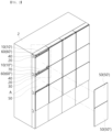
- FIG. 1 is a perspective view of a panel structure according to an exemplary embodiment of the present invention.
- FIG. 2 is a perspective view illustrating a state in which panels of a panel structure according to an exemplary embodiment of the present invention are separated.
- FIG. 3 is an enlarged view of part A of FIG. 2 .
- FIG. 4 is a view illustrating a state in which a first panel connection member and a second panel connection member are combined according to an exemplary embodiment of the present invention.
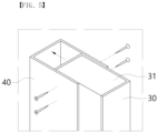
- FIG. 5 is a perspective view of a second frame and a second frame bracket of a panel structure according to an exemplary embodiment of the present invention.
- FIG. 1 it will be described by defining the X-axis as a first direction and a right direction, the Y-axis as a third direction and a front direction, and the Z-axis as a second direction and an upward direction.
- a panel structure 1 provides a structure for coupling a panel 50 to an outer surface of a wall 2 of a building (not shown).
- the panel structure 1 according to an embodiment of the present invention includes a first frame 10, a first frame bracket 20, a second frame 30, a second frame bracket 40, a panel 50, a first panel connection member 60, and a second panel connection member 70.
- first frames 10 may be provided.
- the first frames 10 extends in the first direction (X), that is, to the right, and is arranged spaced apart at a predetermined interval toward the second direction (Z) perpendicular to the first direction (X), that is, upward.
- the plurality of first frames 10 are coupled to the outer surface of the wall 2.
- the first frame 10 may be directly coupled to the wall 2, or may be coupled to the wall 2 by the second frame 30.
- a description of the second frame 30 will be provided later.
- the first frame 10 is formed in a 'C' shape with a cross-section perpendicular to the first direction (X) open toward the third direction (Y).
- the first frame 10 is a section shape steel with a space formed therein, and is formed in a shape that is partly or entirely open along the first direction (X) in the third direction (Y), that is, forward.
- the inner space of the first frame 10 is formed to enable communication with the outside through the third direction (Y).
- a protrusion 11 is formed at the fore end of the first frame 10 in the third direction (Y). More specifically, the protrusion 11 protrudes upward from a lower end of the first frame 10 in the third direction (Y).
- the protrusion 11 may further include an additional protrusion 12 protruding downward from an upper end of the first frame 10 in the third direction (Y).
- the first frame 10 can be installed on the wall regardless of the up-down direction of the first frame 10, and the rigidity of the first frame 10 can be further increased.
- the first frame 10 may be directly coupled to the wall 2, but a second frame 30 is disposed between the first frame 10 and the wall 2 to provide a space for insulating between the first frame 10 and the wall 2 and to easily couple the first frame 10 to the wall 2.
- the second frame 30 is formed to extend in the second direction (Z).
- the shape of the second frame 30 There are no restrictions on the shape of the second frame 30. That is, as long as a surface capable of coupling the first frame 10 is formed in the third direction (Y), there is no limit to the shape and a section shape steel of a known shape can be used.
- a thermal insulating material 31 may be disposed inside the second frame 30.
- the thermal insulating material 31 may be made of a material with known thermal insulating properties.
- the thermal insulating material 31 extends in the second direction (Z), like the second frame 30.
- the thermal insulating material 31 can be deformed and inserted into the interior of the second frame 30, so there is no limit to its shape.
- the fact that the thermal insulating material 31 can be disposed inside the second frame 30 does not mean that the thermal insulating material must be disposed only inside the second frame 30, and although not shown in the drawing, a thermal insulating material may be additionally disposed between the plurality of second frames 30.
- the second frame 30 may be formed in a 'C' shape that is open in the first direction (X) or in a direction opposite to the first direction (X). Accordingly, the second frame 30 allows the thermal insulating material 31 to be easily inserted into the interior of the second frame 30 through the open side.
- the second frame 30 may be directly fixed to the wall 2.
- a second frame bracket 40 may be provided to fix the second frame 30 so that the second frame 30 may be easily fixed to the wall 2 with the thermal insulating material 31 inserted into the second frame 30, and thus it may be able to adjust the verticality of the panel 50 even if the wall 2 is not formed flat, and as well as to adjust the construction error of the second frame 30 in the third direction (Y).
- the second frame bracket 40 couples the second frame 30 to the outer surface of the wall 2 facing the outside of the building as the surface of the third direction (Y) side. There is no limitation to the method by which the second frame bracket 40 fixes the second frame 30 to the outer surface of the wall 2.
- the second frame bracket 40 is formed in a 'C' shape with a cross-section perpendicular to the second direction (Z) open toward the third direction (Y) so that the second frame 30 can be inserted.
- the second frame bracket 40 is installed on the outer surface of the wall 2 using known components. If the wall 2 is made of concrete, the second frame bracket 40 may be installed on the wall 2 using an anchor.
- the rear side of the second frame bracket 40 in the direction opposite to the third direction Y, is formed in a shape corresponding to the outer surface of the wall 2.
- Both sides of the second frame bracket 40 are formed in shapes corresponding to the left and right surfaces of the second frame 30. Accordingly, the left and right surfaces of the second frame 30 can be easily coupled to the second frame bracket 40 while being in contact with the inner surface of the second frame bracket 40.
- the left and right surfaces of the second frame bracket 40 serve to guide the second frame 30, allowing the operator to easily insert the second frame 30 into the second frame bracket 40.
- FIG. 6 is a perspective view of a first frame bracket of a panel structure according to an exemplary embodiment of the present invention.
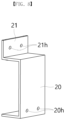
- FIG. 7 is a side view of a first frame bracket of a panel structure according to an exemplary embodiment of the present invention.
- FIG. 8 is a perspective view of a modified example of a first frame bracket of a panel structure according to an exemplary embodiment of the present invention.
- FIG. 9 is a side view of a modified example of a first frame bracket of a panel structure according to an exemplary embodiment of the present invention.
- the first frame 10 is coupled to the second frame 30.
- the first frame 10 may be directly coupled to the second frame 30, or may be coupled to the second frame 30 through the first frame bracket 20.
- the first frame 10 is coupled to the second frame 30 by the first frame bracket 20.
- the first frame 10 can be stably supported by compensating for rotation or sagging of the first frame 20.
- the first frame bracket 20 may couple the first frame 10 to the second frame 30.
- the first frame bracket 20 may directly fix the first frame 10 to the outer surface of the wall 2.
- the first frame bracket 20 is formed to cover the top surface, front surface, and bottom surface of the first frame 10.
- the first frame bracket 20 has a 'C' shaped structure that is open to the rear.
- the first frame bracket 20 includes a first wing 21 protruding upward from the first frame bracket 20.
- the first wing 21 provides an area where the first frame bracket 20 and the second frame 30 can be fixed, while the first frame bracket 20 covers the top surface, the front surface and the bottom surface of the first frame 10.
- a first wing hole 21h is formed in the first wing 21, and a first wing hole screw 21t is inserted into the first wing hole 21h so that the first wing 21 is fixed to the second frame 30.
- the first frame 10 can be fixed to the second frame 30 without welding the first frame bracket 20 to the second frame 30.
- the first frame bracket 20 may further include a second wing 22 protruding downward from the first frame bracket 20.
- the second wing 22 is preferably formed symmetrically with the first wing 21, but is not limited thereto.
- a second wing hole screw 22t is inserted into a second wing hole 22h formed in the second wing 22 so that the second wing 22 is also fixed to the second frame 30.
- the first frame 10 can be stably fixed to the second frame 30 through the first frame bracket 20, and the shape of the first frame bracket 20 is simple, making it easy to manufacture.
- the second wing 22 may not be provided. This is because when the first frame 10 disposed at the bottom of the second frame 30 is provided with the second wing 22, the second wing 22 may be exposed to the outside by protruding lower than the bottom of the second frame 30.
- first frame 10 disposed at the lower end of the second frame 30 can be installed at a predetermined height from the ground, that is, when the first frame 10 disposed at the lower end of the second frame 30 is not disposed at the bottom of the second frame 30, there is no need to use the first frame bracket 20 without the second wing 22.
- the first frame 10 is fixed to the second frame 30 through the first wing hole 21h formed in the first wing 21 and a first frame bracket hole 20h formed in the body of the first frame bracket 20.
- the protrusion 11 provides a structure that can be combined with a first panel connection member 60, which will be described later, and at the same time provides a structure in which the first frame bracket hole screw 20t inserted through the first frame bracket hole 20h formed in the body of the first frame bracket 20 can fix the first frame bracket 20 and the first frame 10.
- FIG. 9 it was described that the first frame 10 disposed at the end of the second frame 30 is placed at the lower end of the second frame 30 as an example, but even in the case where the first frame 10 is placed at the upper end of the second frame 30, the same application may be applied except that the direction in which the first frame bracket 20 is placed is different.
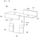
- FIG. 10 is a perspective view of a first panel connection member according to an exemplary embodiment of the present invention.
- FIG. 11 is a perspective view of a second panel connection member according to an exemplary embodiment of the present invention.
- FIG. 12 is a side view illustrating a state in which a first panel connection member and a second panel connection member are coupled to a first frame according to an exemplary embodiment of the present invention.
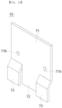
- FIG. 13 is a view illustrating a state in which a first panel connection member and a second panel connection member are fixed to a panel according to an exemplary embodiment of the present invention.
- the first panel connection member 60 is coupled to the first frame 10.
- a plurality of first panel connection member 60 are provided.
- the plurality of first panel connection members 60 are coupled to the plurality of first frames 10 by the necessary number.
- the first panel connection member 60 includes a first horizontal plate 62. As shown in FIG. 12 , the first horizontal plate 62 is in contact with the surface of the second direction (Z) side, that is, the top surface, of the first frame 10.
- the shape of the first horizontal plate 62 is not limited, as long as it can cover the top surface of the first frame 10.
- the first horizontal plate 62 is fixed to the first frame 10.
- a first horizontal plate hole 62h is formed in the first horizontal plate 62, and the first panel connection member 60 may be fixed to the first frame 10 by inserting a first horizontal plate hole screw 62t into the first horizontal plate hole 62h.
- the first horizontal plate 62 may extend in the first direction (X).
- a plurality of first horizontal plate holes 62h may be formed in the first horizontal plate 62. In the present embodiment, it is described that one is formed on the left and right, respectively.
- a first vertical plate 61 protruding downward is provided on the front side of the first horizontal plate 62.
- the first vertical plate 61 covers the front surface of the first frame 10. To this end, as shown in FIG. 12 , it extends downwards at least up to the protrusion 11.
- the first vertical plate 61 is disposed to contact the front surface of the first frame 10.
- a first vertical plate hole 61h is formed in the first vertical plate 61, and the first vertical plate 61 may be coupled to the panel 50, which will be described later, by inserting a first vertical plate hole screw 61t into the first vertical plate hole 61h.
- the first panel connection member 60 includes a first support part 65 and a second support part 66 extending downward from the first vertical plate 61.
- the first support part 65 is formed integrally with the first vertical plate 61 and extends lower than the first vertical plate 61. Accordingly, as shown in FIG. 12 , the first support part 65 comes into contact with the front surface of the protrusion 11.
- the second support part 66 is also formed integrally with the first vertical plate 61. It extends lower than the first vertical plate 61, but unlike the first support part 65, the second support part 66 is bent toward the inside of the first frame 10.
- the second support part 66 is bent toward the inside of the first frame 10 and the second support part 66 can support a part or all of the inner surface of the protrusion 11 of the first frame 10, there is no limit to the shape in which the second support part 66 is bent.
- the second support part 66 may be bent once and the second support part 66 may be formed to support the upper end of the protrusion 11.
- the second support part 66 is bent twice.
- the second support part 66 may be formed by being bent backward from the first vertical plate 61 and then bent forward again. Accordingly, the front surface of the second support part 66 may come into contact with the rear surface of the protrusion 11.
- the protrusion 11 may remain positioned between the second support part 66 and the first support part 65 of the first panel connection member 60 by the load of the panel 50 described later and the shape of the first panel connection member 60.
- the second support part 66 and the first support part 65 also serve to guide in a process of structurally coupling the first panel connection member 60 to the first frame 10 before fixing the first panel connection member 60 using screws.
- the second support part 66 may be formed as a pair. It is preferable that the pair of second support parts 66 are formed on both sides of the first support part 65.
- the pair of second support parts 66 are formed symmetrically on both sides of the first support part 65, thereby preventing the first panel connection member 60 from rotating in one direction during the coupling process.
- the second support part 66 and the first support part 65 may be formed by cutting a plate integrally with the first vertical plate 61. Through this, not only may the structures of the second support part 66 and the first support part 65 be easily manufactured, but also the first panel connection member 60 may be manufactured with a minimum amount of material.
- the first panel connection member 60 includes a locking part 64 protruding downward from the rear side of the first horizontal plate. As shown in FIG. 12 , the locking part 64 is disposed opposite to the first vertical plate 61 with the first frame 10 in the center.
- the locking part 64 comes into contact with the rear surface of the first frame 10. Accordingly, the top surface of the first frame 10 is in contact with the first horizontal plate 62, the front surface of the first frame 10 is in contact with the first vertical plate 61, and the rear surface of the first frame 10 is in contact with the locking part 64, whereby the first panel connection member 60 may be locked and coupled with the first frame 10. That is, by providing the locking part 64, it is possible to prevent the first panel connection member 60 from being separated forward due to the load of the panel 50, which will be described later.
- the locking part 64 protrudes downward so that its lower end is located above the second support part 66. Through this, it is possible to prevent from being disturbed by the locking part 64 in the process of inserting the second support part 66 into the first frame 10.
- the first panel connection member 60 includes a connection part 63 extending upward from the first horizontal plate 62.
- the connection part 63 may be integrally formed with the first horizontal plate 62.
- connection part 63 When the connection part 63 is formed by extending the first horizontal plate 62 in the first direction (X) or in a direction opposite to the first direction (X), it may be formed to protrude upward from the extended portion of the first horizontal plate 62.
- connection part 63 is located in parallel with the first vertical plate 61 in the first direction (X). Accordingly, the connection part 63 can be formed by bending a portion of the front of the first vertical plate 61. Through this, not only can the connection part 63 be easily manufactured, but it is also possible to manufacture the first panel connection member 60 by minimizing the material.
- connection part 63 As shown in FIG. 12 , as for the connection part 63, the front surface of the connection part 63 is located rearward than the front surface of the second vertical plate 71. More specifically, the front surface of the connection part 63 is located rearward than the front surface of the second vertical plate 71 of the second panel connection member 70, which will be described later, by the front-rear direction thickness d of the second vertical plate 71.
- the third direction (Y) surface of the second vertical plate 71 and the third direction (Y) surface of the first vertical plate 61 are located on the same plane. That is, the panel 50 coupled to the second panel connection member 70 and the first panel connection member 60 can be arranged parallel to the front surfaces of the second frame 30 and the first frame 10. In addition, the outer surface of the panel 50 coupled to the first frame 10 in the up-down direction can be arranged on the same plane.
- the second panel connection member 70 is coupled to the first frame 10 by being coupled to the first panel connection member 60.
- the second panel connection member 70 includes a second vertical plate 71.
- the panel 50 is fixed to the front surface of the second vertical plate 71.
- a second vertical plate hole 71h is formed in the second vertical plate 71, and a second vertical plate hole screw 71t is inserted into the second vertical plate hole 71h so that the second vertical plate 71 is fixed to the panel 50.
- a pair of second vertical plate holes 71h are formed in the left-right direction.
- the second panel connection member 70 includes a third support part 72 and a fourth support part 73 to be coupled to the first panel connection member 60.
- the third support part 72 extends downward from the second vertical plate 71 and contacts the front surface of the connection part 63 of the first panel connection member 60 in the third direction (Y).
- the third support part 72 may be integrally formed with the second vertical plate 71.
- the fourth support part 73 is also formed integrally with the second vertical plate 71.
- the fourth support part 73 also extends lower than the second vertical plate 71, but unlike the third support part 72, the fourth support part 73 is bent toward the rear of the connection part 63.
- the fourth support part 73 is bent toward the rear of the connection part 63 and the second support part 66 can support a part or all of the rear surface of the connection part 63 of the first panel connection member 60, there is no limit to the shape in which the fourth support part 73 is bent.
- the fourth support part 73 may be bent once and the fourth support part 73 may be formed to support the rear upper end of connection part 63.
- the fourth support part 73 is bent twice.
- the fourth support part 73 may be formed by being bent backward from the second vertical plate 71 and then bent forward again. Accordingly, the front surface of the fourth support part 73 may come into contact with the rear surface of the connection part 63.
- connection part 63 may remain positioned between the fourth support part 73 and the third support part 72 of the second panel connection member 70 by the load of the panel 50 described later and the shape of the second panel connection member 70.
- the fourth support part 73 may be formed as a pair. It is preferable that the pair of fourth support parts 73 are formed on both sides of the third support part 72.
- the pair of fourth support parts 73 are formed symmetrically on both sides of the third support part 72, thereby preventing the second panel connection member 70 from rotating in one direction during the coupling process.
- the fourth support part 73 and the third support part 72 may be formed by cutting a plate integrally with the second vertical plate 71. Through this, not only may the structures of the fourth support part 73 and the third support part 72 be easily manufactured, but also the second panel connection member 70 may be manufactured with a minimum amount of material.
- the first panel connection member 60 and the second panel connection member 70 are coupled to the panel 50.
- the position or number of the first panel connection member 60 and the second panel connection member 70 fixed on the panel 50 may vary depending on the shape of the panel 50.
- the panel 50 may be coupled in a variety of ways known to the front surface of the first vertical plate 61 of the first panel connection member 60 and the front surface of the second vertical plate 71 of the second panel connection member 70. For example, it may be fastened using an adhesive or using a screw, as described above.
- the panel 50 is formed in a rectangular plate shape, as shown in FIG. 13 , and a pair of first panel connection members 60 are fixed to the upper part of the panel 50 and a pair of second panel connection members 70 are fixed to the lower part of the panel 50 in order to couple the upper and lower parts of the panel 50 to the first frame 10.
- the pair of first panel connection members 60 are placed on opposing sides of the upper part of the panel 50, and the pair of second panel connection members 70 are placed on opposing sides of the lower part of the panel 50.
- the first panel connection member 60 fixed to the upper part of the panel 50 is defined as one first panel connection member 60'.
- the first frame 10 to which the one first panel connection member 60' is coupled is defined as one first frame 10', and the first frame 10 disposed on a lower side adjacent to one first frame 10' is defined as the other first frame 10".
- the panel 50 to which one first panel connection member 60' is fixed is defined as one panel 50', and the panel 50 disposed on a lower side adjacent to one panel 50' is defined as the other panel 50".
- the first panel connection member 60 fixed to the upper part of the other panel 50" is defined as the other first panel connection member 60
- the other first panel connection member 60" is coupled to the other first frame 10".
- a pair of second panel connection members 70 of the one panel 50' are coupled to a pair of the other first panel connection members 60" of the other panel 50", respectively. That is, the connection part 63 of the other first panel connection member 60" is inserted between the fourth support part 73 and the third support part 72 of the second panel connection member 70.
- the second vertical plate 71 of the second panel connection member 70 fixed to one panel 50' is disposed in the opposite direction of the second direction (Z), that is, lower side, of one connection part 63 of one first panel connection member 60'.
- first panel connection member 2 wall 61 first vertical plate 10 first frame 61h first vertical plate hole 11 protrusion 61t first vertical plate hole screw 12 additional protrusion 62 first horizontal plate 20 first frame bracket 62h first horizontal plate hole 20h first frame bracket hole 62t first horizontal plate hole screw 20t first frame bracket hole screw 63 connection part 21 first wing 64 locking part 21h first wing hole 65 first support part 21t first wing hole screw 66 second support part 22 second wing 70 second panel connection member 22h second wing hole 71 second vertical plate 22t second wing hole screw 71h second vertical plate hole 30 second frame 71t second vertical plate hole screw 31 thermal insulating material 72 third support part 40 second frame bracket 73 fourth support part 50 panel
Landscapes
- Engineering & Computer Science (AREA)
- Architecture (AREA)
- Civil Engineering (AREA)
- Structural Engineering (AREA)
- Connection Of Plates (AREA)
Abstract
A panel structure is provided. The panel structure according to an aspect of the present invention includes a plurality of first frames extending in a first direction and spaced apart at predetermined intervals along a second direction perpendicular to the first direction; a plurality of first panel connection members coupled to the first frame; a second panel connection member coupled to the first panel connection member; a panel in which the first panel connection member coupled to one of the two adjacent first frames is fixed to one side, and the second panel connection member coupled to the other of the two adjacent first frames is fixed to the other side; a second frame disposed between the first frame and a wall and extending in the second direction; a first frame bracket coupling the first frame to the second frame; and a second frame bracket that couples the second frame to a surface of the wall in a third direction and whose cross-section perpendicular to the second direction is open toward the third direction so that the second frame can be inserted, wherein the second frame has a thermal insulating material extending in the second direction disposed therein, and the thermal insulating material is disposed between the plurality of second frames.
Description
- This application claims priority to and the benefit of
Korean Patent Application Nos. 10-2022-0180990, filed on December 21, 2022 10-2023-0073147, filed on June 07, 2023 - The present invention relates to a panel structure, and more particularly, to a panel structure that can be replaceably coupled to a wall of a building.
- Panels installed on the walls of buildings not only directly protect the walls from the external environment, but also provide thermal insulating and soundproofing effects. Additionally, panels allow the exterior of a building to be improved by replacing the panels even if the wall itself is not repaired.
- In this case, various materials such as stone, metal, and solar panels are used for the panel. Accordingly, a separate structure is installed on the wall to install each panel.
- In the past, there was a problem that welding was performed to install panels on a structure, which could cause a fire accident at a construction site. Accordingly, there is a growing demand for a structure that can install panels on a wall without welding.
- The present invention is to solve the above problems and is directed to providing a panel structure that can prevent fire by installing the panel without welding.
- The present invention is directed to providing a panel structure that can easily install a panel and increase the thermal insulating effect.
- The problems of the present invention are not limited to those mentioned above, and other problems not mentioned will be clearly understood by those of ordinary skill in the art from the following description.
- In order to solve such problems, the panel structure according to an aspect of the present invention may include a plurality of first frames extending in a first direction and spaced apart at predetermined intervals along a second direction perpendicular to the first direction; a plurality of first panel connection members coupled to the first frame; a second panel connection member coupled to the first panel connection member; a panel in which the first panel connection member coupled to one of the two adjacent first frames is fixed to one side, and the second panel connection member coupled to the other of the two adjacent first frames is fixed to the other side; a second frame disposed between the first frame and a wall and extending in the second direction; a first frame bracket coupling the first frame to the second frame; and a second frame bracket that couples the second frame to a surface of the wall in a third direction and whose cross-section perpendicular to the second direction is open toward the third direction so that the second frame can be inserted, wherein the second frame has a thermal insulating material extending in the second direction disposed therein, and the thermal insulating material is disposed between the plurality of second frames.
- In this case, the first panel connection member may include a first horizontal plate in contact with a surface of the first frame in the second direction, and a first vertical plate that protrudes from one side of the first horizontal plate and contacts a surface of the first frame in a third direction perpendicular to the first direction and the second direction, and one side of the panel may be fixed to the outer surface of the first vertical plate.
- In this case, the first frame may be formed in a 'C' shape with a cross-section perpendicular to the first direction open toward the third direction and have a protrusion protruding in the second direction, and the first panel connection member may further include a first support part extending from the first vertical plate and contacting a portion or all of a surface of the protrusion in the third direction, and a second support part extending from the first vertical plate and contacting a part or all of a surface of the protrusion in an opposite direction to the third direction.
- In this case, the second support part may be formed as a pair, and the pair of second support parts may be formed on both sides of the first support part, respectively.
- In this case, the first panel connection member may further include a locking part protruding from the other side of the first horizontal plate and contacting a surface of the first frame in a direction opposite to the third direction, and the locking part may be formed such that its fore end is located closer to the second direction than the second support part.
- In this case, the first panel connection member may further include a connection part extending from the first horizontal plate in a direction opposite to the second direction, and the second panel connection member may include a second vertical plate with one side thereof in contact with a surface of the first frame in the third direction and the panel fixed to the other side thereof, a third support part extending from the second vertical plate and contacting a part or all of the connection part in the third direction, and a fourth support part extending from the second vertical plate and contacting a part or all of a surface of the connection part in an opposite direction to the third direction.
- In this case, the fourth support part may be formed as a pair, and the pair of fourth support parts may be formed on both sides of the third support part, respectively.
- In this case, the connection part may have a surface in the third direction located on a side opposite to the third direction than a surface of the second vertical plate in the third direction.
- In this case, the connection part may be formed on a side of the first vertical plate in the first direction or in a direction opposite to the first direction.
- In this case, the first frame bracket may include a first wing protruding in the second direction of the first frame bracket, a hole may be formed in the first wing, and a screw may be inserted into the hole to fix the first wing to the second frame.
- In this case, the first frame bracket may further include a second wing protruding in a direction opposite to the second direction of the first frame bracket, a hole may be formed in the second wing, and a screw may be inserted into the hole to fix the second wing to the second frame.
- In this case, the second frame may be such that the thermal insulating material is open in the first direction or in a direction opposite to the first direction.
- In this case, the panel may be provided in plural pieces, and a pair of second panel connection members among the plurality of second panel connection members may be respectively fixed to opposing sides of an end in a direction opposite to the second direction of one panel of the plurality of panels, and a pair of one first panel connection members among the plurality of first panel connection members may be respectively fixed to opposing sides of an end in the second direction.
- In this case, a pair of other first panel connection members among the plurality of first panel connection members may be respectively fixed to opposing sides of an end in a direction opposite to the second direction of the other panel of the plurality of panels, and a pair of the other first panel connection members may be respectively coupled to a pair of the one second panel connection members of the one panel.
- In this case, one second vertical plate of the one second panel connection member may be disposed on a side in a direction opposite to the second direction of a connection part of the one first panel connection member.
- The panel structure according to an embodiment of the present invention includes a first panel connection member and a second panel connection member to which a panel installed on a wall of a building can be connected, so that the panel can be installed without welding, thereby preventing fire.
- The panel structure according to an embodiment of the present invention includes a second frame and a first frame between a panel and a wall of a building, so that the panel can be easily installed and the thermal insulating effect can be improved.
- Advantageous effects of the present invention are not limited to the above-described effects, and should be understood to include all effects that can be inferred from the configuration of the invention described in the description or claims of the present invention.
-
-
FIG. 1 is a perspective view of a panel structure according to an exemplary embodiment of the present invention. -
FIG. 2 is a perspective view illustrating a state in which panels of a panel structure according to an exemplary embodiment of the present invention are separated. -
FIG. 3 is an enlarged view of part A ofFIG. 2 . -
FIG. 4 is a view illustrating a state in which a first panel connection member and a second panel connection member are combined according to an exemplary embodiment of the present invention. -
FIG. 5 is a perspective view of a second frame and a second frame bracket of a panel structure according to an exemplary embodiment of the present invention. -
FIG. 6 is a perspective view of a first frame bracket of a panel structure according to an exemplary embodiment of the present invention. -
FIG. 7 is a side view of a first frame bracket of a panel structure according to an exemplary embodiment of the present invention. -
FIG. 8 is a perspective view of a modified example of a first frame bracket of a panel structure according to an exemplary embodiment of the present invention. -
FIG. 9 is a side view of a modified example of a first frame bracket of a panel structure according to an exemplary embodiment of the present invention. -
FIG. 10 is a perspective view of a first panel connection member according to an exemplary embodiment of the present invention. -
FIG. 11 is a perspective view of a second panel connection member according to an exemplary embodiment of the present invention. -
FIG. 12 is a side view illustrating a state in which a first panel connection member and a second panel connection member are coupled to a first frame according to an exemplary embodiment of the present invention. -
FIG. 13 is a view illustrating a state in which a first panel connection member and a second panel connection member are fixed to a panel according to an exemplary embodiment of the present invention. - Hereinafter, exemplary embodiments of the present invention will be described in detail so that those of ordinary skill in the art can readily implement the present invention with reference to the accompanying drawings. The present invention may be embodied in many different forms and is not limited to the embodiments set forth herein. In the drawings, parts unrelated to the description are omitted for clarity of description of the present invention, and throughout the specification, same or similar reference numerals denote same elements.
- Terms and words used in the present specification and claims should not be construed as limited to their usual or dictionary definition. They should be interpreted as meaning and concepts consistent with the technical idea of the present invention, based on the principle that inventors may appropriately define the terms and concepts to describe their invention in the best way.
- Accordingly, the embodiments described in the present specification and the configurations shown in the drawings correspond to preferred embodiments of the present invention, and do not represent all the technical idea of the present invention, so the configurations may have various examples of equivalent and modification that can replace them at the time of filing the present invention.
- It should be understood that the terms "comprise" or "have" or the like when used in this specification, are intended to describe the presence of stated features, integers, steps, operations, elements, components and/or a combination thereof but not preclude the possibility of the presence or addition of one or more other features, integers, steps, operations, elements, components, or a combination thereof.
- The presence of an element in/on "front" , "rear" , "upper or above or top" or "lower or below or bottom" of another element includes not only being disposed in/on "front", "rear" , "upper or above or top" or "lower or below or bottom" directly in contact with other elements, but also cases in which another element being disposed in the middle, unless otherwise specified. In addition, unless otherwise specified, that an element is "connected" to another element includes not only direct connection to each other but also indirect connection to each other.
- Hereinafter, a panel structure according to an exemplary embodiment of the present invention will be described with reference to the accompanying drawings.
FIG. 1 is a perspective view of a panel structure according to an exemplary embodiment of the present invention.FIG. 2 is a perspective view illustrating a state in which panels of a panel structure according to an exemplary embodiment of the present invention are separated.FIG. 3 is an enlarged view of part A ofFIG. 2 .FIG. 4 is a view illustrating a state in which a first panel connection member and a second panel connection member are combined according to an exemplary embodiment of the present invention.FIG. 5 is a perspective view of a second frame and a second frame bracket of a panel structure according to an exemplary embodiment of the present invention. - In this case, in
FIG. 1 , it will be described by defining the X-axis as a first direction and a right direction, the Y-axis as a third direction and a front direction, and the Z-axis as a second direction and an upward direction. - As shown in
FIG. 1 , apanel structure 1 according to an embodiment of the present invention provides a structure for coupling apanel 50 to an outer surface of awall 2 of a building (not shown). To this end, thepanel structure 1 according to an embodiment of the present invention includes afirst frame 10, afirst frame bracket 20, asecond frame 30, asecond frame bracket 40, apanel 50, a firstpanel connection member 60, and a secondpanel connection member 70. - As shown in
FIG. 2 , a plurality offirst frames 10 may be provided. In this case, thefirst frames 10 extends in the first direction (X), that is, to the right, and is arranged spaced apart at a predetermined interval toward the second direction (Z) perpendicular to the first direction (X), that is, upward. - As shown in
FIG. 3 , the plurality offirst frames 10 are coupled to the outer surface of thewall 2. In this case, thefirst frame 10 may be directly coupled to thewall 2, or may be coupled to thewall 2 by thesecond frame 30. A description of thesecond frame 30 will be provided later. - As shown in
FIG. 4 , thefirst frame 10 is formed in a 'C' shape with a cross-section perpendicular to the first direction (X) open toward the third direction (Y). To explain this in more detail, thefirst frame 10 is a section shape steel with a space formed therein, and is formed in a shape that is partly or entirely open along the first direction (X) in the third direction (Y), that is, forward. - Accordingly, the inner space of the
first frame 10 is formed to enable communication with the outside through the third direction (Y). In this case, aprotrusion 11 is formed at the fore end of thefirst frame 10 in the third direction (Y). More specifically, theprotrusion 11 protrudes upward from a lower end of thefirst frame 10 in the third direction (Y). - In this case, as shown in
FIG. 4 , theprotrusion 11 may further include anadditional protrusion 12 protruding downward from an upper end of thefirst frame 10 in the third direction (Y). By providing such anadditional protrusion 12, thefirst frame 10 can be installed on the wall regardless of the up-down direction of thefirst frame 10, and the rigidity of thefirst frame 10 can be further increased. - The
first frame 10 may be directly coupled to thewall 2, but asecond frame 30 is disposed between thefirst frame 10 and thewall 2 to provide a space for insulating between thefirst frame 10 and thewall 2 and to easily couple thefirst frame 10 to thewall 2. - As shown in
FIG. 5 , thesecond frame 30 is formed to extend in the second direction (Z). There are no restrictions on the shape of thesecond frame 30. That is, as long as a surface capable of coupling thefirst frame 10 is formed in the third direction (Y), there is no limit to the shape and a section shape steel of a known shape can be used. - In this case, a thermal insulating
material 31 may be disposed inside thesecond frame 30. The thermal insulatingmaterial 31 may be made of a material with known thermal insulating properties. The thermal insulatingmaterial 31 extends in the second direction (Z), like thesecond frame 30. In this case, the thermal insulatingmaterial 31 can be deformed and inserted into the interior of thesecond frame 30, so there is no limit to its shape. The fact that the thermal insulatingmaterial 31 can be disposed inside thesecond frame 30 does not mean that the thermal insulating material must be disposed only inside thesecond frame 30, and although not shown in the drawing, a thermal insulating material may be additionally disposed between the plurality of second frames 30. - As shown in
FIG. 5 , thesecond frame 30 may be formed in a 'C' shape that is open in the first direction (X) or in a direction opposite to the first direction (X). Accordingly, thesecond frame 30 allows the thermal insulatingmaterial 31 to be easily inserted into the interior of thesecond frame 30 through the open side. - The
second frame 30 may be directly fixed to thewall 2. However, asecond frame bracket 40 may be provided to fix thesecond frame 30 so that thesecond frame 30 may be easily fixed to thewall 2 with the thermal insulatingmaterial 31 inserted into thesecond frame 30, and thus it may be able to adjust the verticality of thepanel 50 even if thewall 2 is not formed flat, and as well as to adjust the construction error of thesecond frame 30 in the third direction (Y). - The
second frame bracket 40 couples thesecond frame 30 to the outer surface of thewall 2 facing the outside of the building as the surface of the third direction (Y) side. There is no limitation to the method by which thesecond frame bracket 40 fixes thesecond frame 30 to the outer surface of thewall 2. - In the present embodiment, as shown in
FIG. 5 , thesecond frame bracket 40 is formed in a 'C' shape with a cross-section perpendicular to the second direction (Z) open toward the third direction (Y) so that thesecond frame 30 can be inserted. - To explain this in more detail, as shown in
FIG. 5 , thesecond frame bracket 40 is installed on the outer surface of thewall 2 using known components. If thewall 2 is made of concrete, thesecond frame bracket 40 may be installed on thewall 2 using an anchor. - It is preferable that the rear side of the
second frame bracket 40, in the direction opposite to the third direction Y, is formed in a shape corresponding to the outer surface of thewall 2. - Both sides of the
second frame bracket 40 are formed in shapes corresponding to the left and right surfaces of thesecond frame 30. Accordingly, the left and right surfaces of thesecond frame 30 can be easily coupled to thesecond frame bracket 40 while being in contact with the inner surface of thesecond frame bracket 40. - In addition, when inserting the
second frame 30 backward toward thesecond frame bracket 40, the left and right surfaces of thesecond frame bracket 40 serve to guide thesecond frame 30, allowing the operator to easily insert thesecond frame 30 into thesecond frame bracket 40. - Meanwhile, as shown in
FIG. 5 , when the first direction (X) side of thesecond frame 30 is open, the non-open side surface of thesecond frame 30 is fixed to one of the inner left and right surfaces of thesecond frame bracket 40. - There is no limitation to the method of coupling the
second frame 30 to thesecond frame bracket 40, and known fixing components can be used. In the present embodiment, with thesecond frame 30 inserted into thesecond frame bracket 40, thesecond frame 30 is fixed to thesecond frame bracket 40 through a piece. -
FIG. 6 is a perspective view of a first frame bracket of a panel structure according to an exemplary embodiment of the present invention.FIG. 7 is a side view of a first frame bracket of a panel structure according to an exemplary embodiment of the present invention.FIG. 8 is a perspective view of a modified example of a first frame bracket of a panel structure according to an exemplary embodiment of the present invention.FIG. 9 is a side view of a modified example of a first frame bracket of a panel structure according to an exemplary embodiment of the present invention. - Meanwhile, as shown in
FIG. 3 , while thesecond frame 30 is fixed to thewall 2 by thesecond frame bracket 40, thefirst frame 10 is coupled to thesecond frame 30. In this case, thefirst frame 10 may be directly coupled to thesecond frame 30, or may be coupled to thesecond frame 30 through thefirst frame bracket 20. In the present embodiment, it is described that thefirst frame 10 is coupled to thesecond frame 30 by thefirst frame bracket 20. As in the present embodiment, by providing thefirst frame bracket 20, thefirst frame 10 can be stably supported by compensating for rotation or sagging of thefirst frame 20. - As shown in
FIG. 3 , while thesecond frame 30 is fixed to thewall 2 by thesecond frame bracket 40, thefirst frame bracket 20 may couple thefirst frame 10 to thesecond frame 30. However, this is a case where thesecond frame 30 is installed between thewall 2 and thefirst frame 10, and if thesecond frame 30 is not placed as necessary, thefirst frame bracket 20 may directly fix thefirst frame 10 to the outer surface of thewall 2. - As shown in
FIG. 6 , thefirst frame bracket 20 is formed to cover the top surface, front surface, and bottom surface of thefirst frame 10. When thefirst frame 10 is formed of a 'C' shaped section shape steel that is open to the front as described above, thefirst frame bracket 20 has a 'C' shaped structure that is open to the rear. - In this case, the
first frame bracket 20 includes afirst wing 21 protruding upward from thefirst frame bracket 20. Thefirst wing 21 provides an area where thefirst frame bracket 20 and thesecond frame 30 can be fixed, while thefirst frame bracket 20 covers the top surface, the front surface and the bottom surface of thefirst frame 10. - As shown in
FIG. 6 , afirst wing hole 21h is formed in thefirst wing 21, and a firstwing hole screw 21t is inserted into thefirst wing hole 21h so that thefirst wing 21 is fixed to thesecond frame 30. Through this, thefirst frame 10 can be fixed to thesecond frame 30 without welding thefirst frame bracket 20 to thesecond frame 30. - In this case, as shown in
FIG. 7 , thefirst frame bracket 20 may further include asecond wing 22 protruding downward from thefirst frame bracket 20. Thesecond wing 22 is preferably formed symmetrically with thefirst wing 21, but is not limited thereto. In this case, a secondwing hole screw 22t is inserted into asecond wing hole 22h formed in thesecond wing 22 so that thesecond wing 22 is also fixed to thesecond frame 30. - By using the
first wing 21 and thesecond wing 22, thefirst frame 10 can be stably fixed to thesecond frame 30 through thefirst frame bracket 20, and the shape of thefirst frame bracket 20 is simple, making it easy to manufacture. - However, as shown in
FIG. 8 , in the case of thefirst frame bracket 20 for fixing thefirst frame 10 disposed at the bottom of thesecond frame 30 to thesecond frame 30, thesecond wing 22 may not be provided. This is because when thefirst frame 10 disposed at the bottom of thesecond frame 30 is provided with thesecond wing 22, thesecond wing 22 may be exposed to the outside by protruding lower than the bottom of thesecond frame 30. - In this case, in
FIG. 8 , the description was made on the assumption that thefirst frame 10 is placed at the lower end of thesecond frame 30 as an example, but even in the case where thefirst frame 10 is placed at the upper end of thesecond frame 30, the same application may be applied except that the direction in which thefirst frame bracket 20 is placed is different. - When the
first frame 10 disposed at the lower end of thesecond frame 30 can be installed at a predetermined height from the ground, that is, when thefirst frame 10 disposed at the lower end of thesecond frame 30 is not disposed at the bottom of thesecond frame 30, there is no need to use thefirst frame bracket 20 without thesecond wing 22. - As shown in
FIG. 8 , in the case of thefirst frame bracket 20 without thesecond wing 22, in order to firmly fix thefirst frame 10, thefirst frame 10 is fixed to thesecond frame 30 through thefirst wing hole 21h formed in thefirst wing 21 and a firstframe bracket hole 20h formed in the body of thefirst frame bracket 20. - As shown in
FIG. 9 , a first framebracket hole screw 20t inserted into the firstframe bracket hole 20h formed in the body of thefirst frame bracket 20 disposed at the bottom of thesecond frame 30 penetrates and is fixed to theprotrusion 11 of thefirst frame 10. Through this, theprotrusion 11 provides a structure that can be combined with a firstpanel connection member 60, which will be described later, and at the same time provides a structure in which the first framebracket hole screw 20t inserted through the firstframe bracket hole 20h formed in the body of thefirst frame bracket 20 can fix thefirst frame bracket 20 and thefirst frame 10. - In this case, in
FIG. 9 , it was described that thefirst frame 10 disposed at the end of thesecond frame 30 is placed at the lower end of thesecond frame 30 as an example, but even in the case where thefirst frame 10 is placed at the upper end of thesecond frame 30, the same application may be applied except that the direction in which thefirst frame bracket 20 is placed is different. -
FIG. 10 is a perspective view of a first panel connection member according to an exemplary embodiment of the present invention.FIG. 11 is a perspective view of a second panel connection member according to an exemplary embodiment of the present invention.FIG. 12 is a side view illustrating a state in which a first panel connection member and a second panel connection member are coupled to a first frame according to an exemplary embodiment of the present invention.FIG. 13 is a view illustrating a state in which a first panel connection member and a second panel connection member are fixed to a panel according to an exemplary embodiment of the present invention. - Meanwhile, as shown in
FIG. 2 , the firstpanel connection member 60 is coupled to thefirst frame 10. In this case, a plurality of firstpanel connection member 60 are provided. The plurality of firstpanel connection members 60 are coupled to the plurality offirst frames 10 by the necessary number. - As shown in
FIG. 10 , the firstpanel connection member 60 includes a firsthorizontal plate 62. As shown inFIG. 12 , the firsthorizontal plate 62 is in contact with the surface of the second direction (Z) side, that is, the top surface, of thefirst frame 10. - The shape of the first
horizontal plate 62 is not limited, as long as it can cover the top surface of thefirst frame 10. The firsthorizontal plate 62 is fixed to thefirst frame 10. To this end, as shown inFIG. 10 , a firsthorizontal plate hole 62h is formed in the firsthorizontal plate 62, and the firstpanel connection member 60 may be fixed to thefirst frame 10 by inserting a first horizontalplate hole screw 62t into the firsthorizontal plate hole 62h. - The first
horizontal plate 62 may extend in the first direction (X). In this case, a plurality of firsthorizontal plate holes 62h may be formed in the firsthorizontal plate 62. In the present embodiment, it is described that one is formed on the left and right, respectively. - A first
vertical plate 61 protruding downward is provided on the front side of the firsthorizontal plate 62. The firstvertical plate 61 covers the front surface of thefirst frame 10. To this end, as shown inFIG. 12 , it extends downwards at least up to theprotrusion 11. - The first
vertical plate 61 is disposed to contact the front surface of thefirst frame 10. In this case, as shown inFIG. 10 , a firstvertical plate hole 61h is formed in the firstvertical plate 61, and the firstvertical plate 61 may be coupled to thepanel 50, which will be described later, by inserting a first verticalplate hole screw 61t into the firstvertical plate hole 61h. - As shown in
FIG. 10 , the firstpanel connection member 60 includes afirst support part 65 and asecond support part 66 extending downward from the firstvertical plate 61. - The
first support part 65 is formed integrally with the firstvertical plate 61 and extends lower than the firstvertical plate 61. Accordingly, as shown inFIG. 12 , thefirst support part 65 comes into contact with the front surface of theprotrusion 11. - As shown in
FIG. 10 , thesecond support part 66 is also formed integrally with the firstvertical plate 61. It extends lower than the firstvertical plate 61, but unlike thefirst support part 65, thesecond support part 66 is bent toward the inside of thefirst frame 10. - In this case, as long as the
second support part 66 is bent toward the inside of thefirst frame 10 and thesecond support part 66 can support a part or all of the inner surface of theprotrusion 11 of thefirst frame 10, there is no limit to the shape in which thesecond support part 66 is bent. For example, thesecond support part 66 may be bent once and thesecond support part 66 may be formed to support the upper end of theprotrusion 11. - However, in the present embodiment, as shown in
FIG. 12 , it is described that thesecond support part 66 is bent twice. To explain this in more detail, thesecond support part 66 may be formed by being bent backward from the firstvertical plate 61 and then bent forward again. Accordingly, the front surface of thesecond support part 66 may come into contact with the rear surface of theprotrusion 11. - As shown in
FIG. 12 , theprotrusion 11 may remain positioned between thesecond support part 66 and thefirst support part 65 of the firstpanel connection member 60 by the load of thepanel 50 described later and the shape of the firstpanel connection member 60. - In addition, the
second support part 66 and thefirst support part 65 also serve to guide in a process of structurally coupling the firstpanel connection member 60 to thefirst frame 10 before fixing the firstpanel connection member 60 using screws. - In this case, as shown in
FIG. 10 , thesecond support part 66 may be formed as a pair. It is preferable that the pair ofsecond support parts 66 are formed on both sides of thefirst support part 65. - Through this, the pair of
second support parts 66 are formed symmetrically on both sides of thefirst support part 65, thereby preventing the firstpanel connection member 60 from rotating in one direction during the coupling process. - The
second support part 66 and thefirst support part 65 may be formed by cutting a plate integrally with the firstvertical plate 61. Through this, not only may the structures of thesecond support part 66 and thefirst support part 65 be easily manufactured, but also the firstpanel connection member 60 may be manufactured with a minimum amount of material. - Meanwhile, as shown in
FIG. 10 , the firstpanel connection member 60 includes a lockingpart 64 protruding downward from the rear side of the first horizontal plate. As shown inFIG. 12 , the lockingpart 64 is disposed opposite to the firstvertical plate 61 with thefirst frame 10 in the center. - The locking
part 64 comes into contact with the rear surface of thefirst frame 10. Accordingly, the top surface of thefirst frame 10 is in contact with the firsthorizontal plate 62, the front surface of thefirst frame 10 is in contact with the firstvertical plate 61, and the rear surface of thefirst frame 10 is in contact with the lockingpart 64, whereby the firstpanel connection member 60 may be locked and coupled with thefirst frame 10. That is, by providing the lockingpart 64, it is possible to prevent the firstpanel connection member 60 from being separated forward due to the load of thepanel 50, which will be described later. - As shown in
FIG. 12 , the lockingpart 64 protrudes downward so that its lower end is located above thesecond support part 66. Through this, it is possible to prevent from being disturbed by the lockingpart 64 in the process of inserting thesecond support part 66 into thefirst frame 10. - Meanwhile, as shown in
FIG. 10 , the firstpanel connection member 60 includes aconnection part 63 extending upward from the firsthorizontal plate 62. Theconnection part 63 may be integrally formed with the firsthorizontal plate 62. - When the
connection part 63 is formed by extending the firsthorizontal plate 62 in the first direction (X) or in a direction opposite to the first direction (X), it may be formed to protrude upward from the extended portion of the firsthorizontal plate 62. - That is, the
connection part 63 is located in parallel with the firstvertical plate 61 in the first direction (X). Accordingly, theconnection part 63 can be formed by bending a portion of the front of the firstvertical plate 61. Through this, not only can theconnection part 63 be easily manufactured, but it is also possible to manufacture the firstpanel connection member 60 by minimizing the material. - As shown in
FIG. 12 , as for theconnection part 63, the front surface of theconnection part 63 is located rearward than the front surface of the secondvertical plate 71. More specifically, the front surface of theconnection part 63 is located rearward than the front surface of the secondvertical plate 71 of the secondpanel connection member 70, which will be described later, by the front-rear direction thickness d of the secondvertical plate 71. - Accordingly, the third direction (Y) surface of the second
vertical plate 71 and the third direction (Y) surface of the firstvertical plate 61 are located on the same plane. That is, thepanel 50 coupled to the secondpanel connection member 70 and the firstpanel connection member 60 can be arranged parallel to the front surfaces of thesecond frame 30 and thefirst frame 10. In addition, the outer surface of thepanel 50 coupled to thefirst frame 10 in the up-down direction can be arranged on the same plane. - As shown in
FIG. 12 , the secondpanel connection member 70 is coupled to thefirst frame 10 by being coupled to the firstpanel connection member 60. To this end, the secondpanel connection member 70 includes a secondvertical plate 71. - The
panel 50 is fixed to the front surface of the secondvertical plate 71. There is no limit to the shape of the secondvertical plate 71 as long as it is formed in the shape of a plate having a predetermined thickness. - As shown in
FIG. 11 , a secondvertical plate hole 71h is formed in the secondvertical plate 71, and a second verticalplate hole screw 71t is inserted into the secondvertical plate hole 71h so that the secondvertical plate 71 is fixed to thepanel 50. There is no limit to the number of secondvertical plate holes 71h formed in the secondvertical plate 71. In the present embodiment, in order to prevent the secondvertical plate 71 fixed to thepanel 50 from rotating, a pair of secondvertical plate holes 71h are formed in the left-right direction. - As shown in
FIG. 11 , the secondpanel connection member 70 includes athird support part 72 and afourth support part 73 to be coupled to the firstpanel connection member 60. - As shown in
FIG. 12 , thethird support part 72 extends downward from the secondvertical plate 71 and contacts the front surface of theconnection part 63 of the firstpanel connection member 60 in the third direction (Y). Thethird support part 72 may be integrally formed with the secondvertical plate 71. - As shown in
FIG. 11 , thefourth support part 73 is also formed integrally with the secondvertical plate 71. Thefourth support part 73 also extends lower than the secondvertical plate 71, but unlike thethird support part 72, thefourth support part 73 is bent toward the rear of theconnection part 63. - In this case, as long as the
fourth support part 73 is bent toward the rear of theconnection part 63 and thesecond support part 66 can support a part or all of the rear surface of theconnection part 63 of the firstpanel connection member 60, there is no limit to the shape in which thefourth support part 73 is bent. For example, thefourth support part 73 may be bent once and thefourth support part 73 may be formed to support the rear upper end ofconnection part 63. Through this, in the process of coupling the secondvertical plate 71 by moving the secondvertical plate 71 from the upper side to the lower side of theconnection part 63, the operator may easily allow theconnection part 63 to be positioned between thefourth support part 73 and thethird support part 72. - However, in the present embodiment, as shown in
FIG. 12 , it is described that thefourth support part 73 is bent twice. Thefourth support part 73 may be formed by being bent backward from the secondvertical plate 71 and then bent forward again. Accordingly, the front surface of thefourth support part 73 may come into contact with the rear surface of theconnection part 63. - As shown in
FIG. 12 , theconnection part 63 may remain positioned between thefourth support part 73 and thethird support part 72 of the secondpanel connection member 70 by the load of thepanel 50 described later and the shape of the secondpanel connection member 70. - In this case, as shown in
FIG. 11 , thefourth support part 73 may be formed as a pair. It is preferable that the pair offourth support parts 73 are formed on both sides of thethird support part 72. - Through this, the pair of
fourth support parts 73 are formed symmetrically on both sides of thethird support part 72, thereby preventing the secondpanel connection member 70 from rotating in one direction during the coupling process. - The
fourth support part 73 and thethird support part 72 may be formed by cutting a plate integrally with the secondvertical plate 71. Through this, not only may the structures of thefourth support part 73 and thethird support part 72 be easily manufactured, but also the secondpanel connection member 70 may be manufactured with a minimum amount of material. - Meanwhile, as shown in
FIG. 13 , in order to couple thepanel 50 to thefirst frame 10, the firstpanel connection member 60 and the secondpanel connection member 70 are coupled to thepanel 50. - In this case, the position or number of the first
panel connection member 60 and the secondpanel connection member 70 fixed on thepanel 50 may vary depending on the shape of thepanel 50. In addition, depending on the type of thepanel 50, thepanel 50 may be coupled in a variety of ways known to the front surface of the firstvertical plate 61 of the firstpanel connection member 60 and the front surface of the secondvertical plate 71 of the secondpanel connection member 70. For example, it may be fastened using an adhesive or using a screw, as described above. - In the present embodiment, the
panel 50 is formed in a rectangular plate shape, as shown inFIG. 13 , and a pair of firstpanel connection members 60 are fixed to the upper part of thepanel 50 and a pair of secondpanel connection members 70 are fixed to the lower part of thepanel 50 in order to couple the upper and lower parts of thepanel 50 to thefirst frame 10. - In this case, in order to stably support the
panel 50, the pair of firstpanel connection members 60 are placed on opposing sides of the upper part of thepanel 50, and the pair of secondpanel connection members 70 are placed on opposing sides of the lower part of thepanel 50. - Meanwhile, the positional and coupling relationship between the first
panel connection member 60 and the secondpanel connection member 70 fixed to thepanel 50 will be described as follows. - As shown in
FIGS. 2 and3 , the firstpanel connection member 60 fixed to the upper part of thepanel 50 is defined as one first panel connection member 60'. It will be described that thefirst frame 10 to which the one first panel connection member 60' is coupled is defined as one first frame 10', and thefirst frame 10 disposed on a lower side adjacent to one first frame 10' is defined as the otherfirst frame 10". - As shown in
FIGS. 1 and2 , it will be described that thepanel 50 to which one first panel connection member 60' is fixed is defined as one panel 50', and thepanel 50 disposed on a lower side adjacent to one panel 50' is defined as theother panel 50". In this case, the firstpanel connection member 60 fixed to the upper part of theother panel 50" is defined as the other firstpanel connection member 60", and the other firstpanel connection member 60" is coupled to the otherfirst frame 10". - A pair of second
panel connection members 70 of the one panel 50' are coupled to a pair of the other firstpanel connection members 60" of theother panel 50", respectively. That is, theconnection part 63 of the other firstpanel connection member 60" is inserted between thefourth support part 73 and thethird support part 72 of the secondpanel connection member 70. - To this end, as shown in
FIG. 13 , the secondvertical plate 71 of the secondpanel connection member 70 fixed to one panel 50' is disposed in the opposite direction of the second direction (Z), that is, lower side, of oneconnection part 63 of one first panel connection member 60'. - As described above, preferred embodiments according to the present invention have been examined, and it is obvious to those skilled in the art that the present invention can be embodied in other specific forms without departing from the spirit or scope of the present invention in addition to the above-described embodiments. Therefore, the above-described embodiments are to be construed as illustrative rather than restrictive, and accordingly, the present invention is not limited to the above description and may be modified within the scope of the appended claims and their equivalents.
-
1 panel structure 60 first panel connection member 2 wall 61 first vertical plate 10 first frame 61h first vertical plate hole 11 protrusion 61t first vertical plate hole screw 12 additional protrusion 62 first horizontal plate 20 first frame bracket 62h first horizontal plate hole 20h first frame bracket hole 62t first horizontal plate hole screw 20t first frame bracket hole screw 63 connection part 21 first wing 64 locking part 21h first wing hole 65 first support part 21t first wing hole screw 66 second support part 22 second wing 70 second panel connection member 22h second wing hole 71 second vertical plate 22t second wing hole screw 71h second vertical plate hole 30 second frame 71t second vertical plate hole screw 31 thermal insulating material 72 third support part 40 second frame bracket 73 fourth support part 50 panel
Claims (15)
- A panel structure, comprising:a plurality of first frames extending in a first direction and spaced apart at predetermined intervals along a second direction perpendicular to the first direction;a plurality of first panel connection members coupled to the first frame;a second panel connection member coupled to the first panel connection member;a panel in which the first panel connection member coupled to one of the two adjacent first frames is fixed to one side, and the second panel connection member coupled to the other of the two adjacent first frames is fixed to the other side;a second frame disposed between the first frame and a wall and extending in the second direction;
a first frame bracket coupling the first frame to the second frame; anda second frame bracket that couples the second frame to a surface of the wall in a third direction and whose cross-section perpendicular to the second direction is open toward the third direction so that the second frame can be inserted,wherein the second frame has a thermal insulating material extending in the second direction disposed therein, and the thermal insulating material is disposed between the plurality of second frames. - The panel structure of claim 1,wherein the first panel connection member comprises a first horizontal plate in contact with a surface of the first frame in the second direction, and a first vertical plate that protrudes from one side of the first horizontal plate and contacts a surface of the first frame in a third direction perpendicular to the first direction and the second direction, andone side of the panel is fixed to the outer surface of the first vertical plate.
- The panel structure of claim 2,wherein the first frame is formed in a 'C' shape with a cross-section perpendicular to the first direction open toward the third direction and has a protrusion protruding in the second direction, andthe first panel connection member further comprises a first support part extending from the first vertical plate and contacting a portion or all of a surface of the protrusion in the third direction, and a second support part extending from the first vertical plate and contacting a part or all of a surface of the protrusion in an opposite direction to the third direction.
- The panel structure of claim 3,wherein the second support part is formed as a pair, andthe pair of second support parts are formed on both sides of the first support part, respectively.
- The panel structure of claim 3,wherein the first panel connection member further comprises a locking part protruding from the other side of the first horizontal plate and contacting a surface of the first frame in a direction opposite to the third direction, andthe locking part is formed such that its fore end is located closer to the second direction than the second support part.
- The panel structure of claim 2,wherein the first panel connection member further comprises a connection part extending from the first horizontal plate in a direction opposite to the second direction, andthe second panel connection member comprises a second vertical plate with one side thereof in contact with a surface of the first frame in the third direction and the panel fixed to the other side thereof, a third support part extending from the second vertical plate and contacting a part or all of the connection part in the third direction, and a fourth support part extending from the second vertical plate and contacting a part or all of a surface of the connection part in an opposite direction to the third direction.
- The panel structure of claim 6,wherein the fourth support part is formed as a pair, andthe pair of fourth support parts are formed on both sides of the third support part, respectively.
- The panel structure of claim 6, wherein the connection part has a surface in the third direction located on a side opposite to the third direction than a surface of the second vertical plate in the third direction.
- The panel structure of claim 6, wherein the connection part is formed on a side of the first vertical plate in the first direction or in a direction opposite to the first direction.
- The panel structure of claim 1,wherein the first frame bracket comprises a first wing protruding in the second direction of the first frame bracket,a hole is formed in the first wing, anda screw is inserted into the hole to fix the first wing to the second frame.
- The panel structure of claim 10,wherein the first frame bracket further comprises a second wing protruding in a direction opposite to the second direction of the first frame bracket,a hole is formed in the second wing, anda screw is inserted into the hole to fix the second wing to the second frame.
- The panel structure of claim 1, wherein the second frame is such that the thermal insulating material is open in the first direction or in a direction opposite to the first direction.
- The panel structure of claim 1,wherein the panel is provided in plural pieces, anda pair of second panel connection members among the plurality of second panel connection members are respectively fixed to opposing sides of an end in a direction opposite to the second direction of one panel of the plurality of panels, and a pair of one first panel connection members among the plurality of first panel connection members are respectively fixed to opposing sides of an end in the second direction.
- The panel structure of claim 13,wherein a pair of other first panel connection members among the plurality of first panel connection members are respectively fixed to opposing sides of an end in a direction opposite to the second direction of the other panel of the plurality of panels, anda pair of the other first panel connection members are respectively coupled to a pair of the one second panel connection members of the one panel.
- The panel structure of claim 13, wherein one second vertical plate of the one second panel connection member is disposed on a side in a direction opposite to the second direction of a connection part of the one first panel connection member.
Applications Claiming Priority (2)
| Application Number | Priority Date | Filing Date | Title |
|---|---|---|---|
| KR20220180990 | 2022-12-21 | ||
| KR1020230073147A KR102698512B1 (en) | 2022-12-21 | 2023-06-07 | Panel structure |
Publications (1)
| Publication Number | Publication Date |
|---|---|
| EP4390007A1 true EP4390007A1 (en) | 2024-06-26 |
Family
ID=89474255
Family Applications (1)
| Application Number | Title | Priority Date | Filing Date |
|---|---|---|---|
| EP23217654.5A Pending EP4390007A1 (en) | 2022-12-21 | 2023-12-18 | Panel structure |
Country Status (1)
| Country | Link |
|---|---|
| EP (1) | EP4390007A1 (en) |
Citations (6)
| Publication number | Priority date | Publication date | Assignee | Title |
|---|---|---|---|---|
| FR2562591A1 (en) * | 1984-04-06 | 1985-10-11 | Gen Batiment | Cladding system for buildings |
| DE3718044A1 (en) * | 1987-05-28 | 1988-12-15 | Maisch F Protektorwerk | Facade cladding |
| DE19957094A1 (en) * | 1998-08-14 | 2001-05-31 | Alfons Knoche | System for fixing anchor part on back of faade plate uses self-tapping screws screwed into predrilled blind holes in faade plate which are guided through guide and assembly bores formed |
| WO2009059392A1 (en) * | 2007-11-08 | 2009-05-14 | Lysyuk, Dmytro | Apparatus and method for installing cladding to structures |
| WO2010012061A1 (en) * | 2008-07-28 | 2010-02-04 | Dmytro Romanovich Lysyuk | Clip and support for installing cladding |
| KR20220053111A (en) * | 2020-10-21 | 2022-04-29 | 아주대학교산학협력단 | Exterior material supporting structure |
-
2023
- 2023-12-18 EP EP23217654.5A patent/EP4390007A1/en active Pending
Patent Citations (6)
| Publication number | Priority date | Publication date | Assignee | Title |
|---|---|---|---|---|
| FR2562591A1 (en) * | 1984-04-06 | 1985-10-11 | Gen Batiment | Cladding system for buildings |
| DE3718044A1 (en) * | 1987-05-28 | 1988-12-15 | Maisch F Protektorwerk | Facade cladding |
| DE19957094A1 (en) * | 1998-08-14 | 2001-05-31 | Alfons Knoche | System for fixing anchor part on back of faade plate uses self-tapping screws screwed into predrilled blind holes in faade plate which are guided through guide and assembly bores formed |
| WO2009059392A1 (en) * | 2007-11-08 | 2009-05-14 | Lysyuk, Dmytro | Apparatus and method for installing cladding to structures |
| WO2010012061A1 (en) * | 2008-07-28 | 2010-02-04 | Dmytro Romanovich Lysyuk | Clip and support for installing cladding |
| KR20220053111A (en) * | 2020-10-21 | 2022-04-29 | 아주대학교산학협력단 | Exterior material supporting structure |
Similar Documents
| Publication | Publication Date | Title |
|---|---|---|
| KR20220062448A (en) | Construction Brackets, Building Wall Structures and Sheet Metal Construction Methods | |
| CN211622028U (en) | Flood component for assembly type building and assembly type building | |
| CN110392760B (en) | Mounting accessories and wall structure of buildings | |
| KR20110015899A (en) | Vertical frame and frame joining structure of steel curtain wall system | |
| KR101860894B1 (en) | Assembly for installing vacuum insulator and method for installing the vacuum insulator using the same | |
| KR102698512B1 (en) | Panel structure | |
| JP4701101B2 (en) | Siding mounting bracket | |
| KR20240169431A (en) | Curtain wall assembly | |
| JP7736583B2 (en) | Horizontal surface material mounting structure | |
| KR102889551B1 (en) | Curtain wall frames structure with modular cladding support units | |
| KR102293621B1 (en) | Non-welding insulation system | |
| JP2025187343A (en) | Interlocking structure of battens and curtain wall units | |
| JP7215968B2 (en) | Connection structure of non-mesh materials | |
| JP7819080B2 (en) | Partition unit | |
| KR102913978B1 (en) | Panel for a formwork | |
| JP6504873B2 (en) | Profile material provided with a heating foamable member and a fitting using the same material | |
| JP5166939B2 (en) | Building opening structure | |
| JP7826060B2 (en) | curtain wall | |
| KR102498775B1 (en) | Structure for finising with panel | |
| KR102421687B1 (en) | Bracket for windows and doors | |
| JP2020109239A (en) | Building wall structure, sash and building wall construction method | |
| JP2024013604A (en) | Multi-window mullion structure and error adjustment method for continuous windows | |
| JP2026066024A (en) | Building walls and buildings | |
| JP3385569B2 (en) | Mounting structure for vertical and horizontal frames | |
| KR20190086087A (en) | Bracket assembly for window frame and construction method thereof |
Legal Events
| Date | Code | Title | Description |
|---|---|---|---|
| PUAI | Public reference made under article 153(3) epc to a published international application that has entered the european phase |
Free format text: ORIGINAL CODE: 0009012 |
|
| STAA | Information on the status of an ep patent application or granted ep patent |
Free format text: STATUS: REQUEST FOR EXAMINATION WAS MADE |
|
| 17P | Request for examination filed |
Effective date: 20231218 |
|
| AK | Designated contracting states |
Kind code of ref document: A1 Designated state(s): AL AT BE BG CH CY CZ DE DK EE ES FI FR GB GR HR HU IE IS IT LI LT LU LV MC ME MK MT NL NO PL PT RO RS SE SI SK SM TR |
|
| STAA | Information on the status of an ep patent application or granted ep patent |
Free format text: STATUS: EXAMINATION IS IN PROGRESS |