EP4389991A1 - Swivel work machine - Google Patents
Swivel work machine Download PDFInfo
- Publication number
- EP4389991A1 EP4389991A1 EP23208084.6A EP23208084A EP4389991A1 EP 4389991 A1 EP4389991 A1 EP 4389991A1 EP 23208084 A EP23208084 A EP 23208084A EP 4389991 A1 EP4389991 A1 EP 4389991A1
- Authority
- EP
- European Patent Office
- Prior art keywords
- swivel
- section
- move
- causing
- angular
- Prior art date
- Legal status (The legal status is an assumption and is not a legal conclusion. Google has not performed a legal analysis and makes no representation as to the accuracy of the status listed.)
- Withdrawn
Links
Images



Classifications
-
- E—FIXED CONSTRUCTIONS
- E02—HYDRAULIC ENGINEERING; FOUNDATIONS; SOIL SHIFTING
- E02F—DREDGING; SOIL-SHIFTING
- E02F9/00—Component parts of dredgers or soil-shifting machines, not restricted to one of the kinds covered by groups E02F3/00 - E02F7/00
- E02F9/26—Indicating devices
- E02F9/264—Sensors and their calibration for indicating the position of the work tool
-
- E—FIXED CONSTRUCTIONS
- E02—HYDRAULIC ENGINEERING; FOUNDATIONS; SOIL SHIFTING
- E02F—DREDGING; SOIL-SHIFTING
- E02F9/00—Component parts of dredgers or soil-shifting machines, not restricted to one of the kinds covered by groups E02F3/00 - E02F7/00
- E02F9/08—Superstructures; Supports for superstructures
- E02F9/10—Supports for movable superstructures mounted on travelling or walking gears or on other superstructures
- E02F9/12—Slewing or traversing gears
- E02F9/121—Turntables, i.e. structure rotatable about 360°
- E02F9/123—Drives or control devices specially adapted therefor
-
- E—FIXED CONSTRUCTIONS
- E02—HYDRAULIC ENGINEERING; FOUNDATIONS; SOIL SHIFTING
- E02F—DREDGING; SOIL-SHIFTING
- E02F9/00—Component parts of dredgers or soil-shifting machines, not restricted to one of the kinds covered by groups E02F3/00 - E02F7/00
- E02F9/26—Indicating devices
-
- E—FIXED CONSTRUCTIONS
- E02—HYDRAULIC ENGINEERING; FOUNDATIONS; SOIL SHIFTING
- E02F—DREDGING; SOIL-SHIFTING
- E02F3/00—Dredgers; Soil-shifting machines
- E02F3/04—Dredgers; Soil-shifting machines mechanically-driven
- E02F3/28—Dredgers; Soil-shifting machines mechanically-driven with digging tools mounted on a dipper- or bucket-arm, i.e. there is either one arm or a pair of arms, e.g. dippers, buckets
- E02F3/30—Dredgers; Soil-shifting machines mechanically-driven with digging tools mounted on a dipper- or bucket-arm, i.e. there is either one arm or a pair of arms, e.g. dippers, buckets with a dipper-arm pivoted on a cantilever beam, i.e. boom
- E02F3/32—Dredgers; Soil-shifting machines mechanically-driven with digging tools mounted on a dipper- or bucket-arm, i.e. there is either one arm or a pair of arms, e.g. dippers, buckets with a dipper-arm pivoted on a cantilever beam, i.e. boom working downwardly and towards the machine, e.g. with backhoes
- E02F3/325—Backhoes of the miniature type
Definitions
- the present invention relates to a swivel work machine including a swivel section, such as an excavator.
- Patent Literature 1 a work machine has been known which is disclosed in Patent Literature 1 and which includes an inclination-angle detection section for detecting an inclination angle of a machine body of the work machine.
- the inclination-angle detection section includes: an acceleration sensor which is mounted to the machine body so as to cause an output from the acceleration sensor with respect to a gravitational acceleration to vary in accordance with the inclination angle of the machine body; and a conversion section for converting, into the inclination angle of the machine, the output from the acceleration sensor.
- inertial sensors inertial measurement units (IMUs)
- IMUs inertial measurement units
- Such an inertial sensor includes an acceleration sensor and an angular-velocity sensor.
- the inertial sensor is configured to measure an angular velocity of the machine body and an acceleration thereof to calculate, for example, a posture angle of the machine body and an azimuth thereof.
- Patent Literature 1 Japanese Patent No. 5297280
- a swivel section thereof swivels.
- This acceleration is regarded as a disturbance acceleration and has an impact on the acceleration used to calculate the posture angle of the swivel work machine.
- the posture angle calculated by the inertial sensor therefore has an error.
- a swivel work machine in accordance with an aspect of the present invention includes: a swivel section; at least one inertial sensor which is disposed on the swivel section and which is configured to calculate a posture angle of the swivel section on the basis of an angular velocity and an acceleration; a detection section configured to detect an operation of causing the swivel section to move; and an output section configured to, in a case where the operation of causing the swivel section to move has been detected, output a signal corresponding to the operation, to the at least one inertial sensor.
- An aspect of the present invention makes it possible to achieve a swivel work machine that enables accurate detection of a posture angle of a swivel section of the swivel work machine even when a disturbance acceleration occurs due to movement of the swivel section.
- Fig. 1 is a side view schematically illustrating a swivel work machine 1 in accordance with the present embodiment.
- an excavator is taken as an example of the swivel work machine 1.
- the present invention also encompasses swivel work machines without traveling devices, such as crane machines.
- the swivel work machine 1 includes a swivel section 2 and a traveling device 3.
- the swivel section 2 is supported on the traveling device 3 so as to be able to swivel about an axis extending in an up-and-down direction.
- the swivel section 2 is driven by a swivel motor 21.
- the traveling device 3 supports the swivel section 2 so as to enable the swivel section 2 to travel and is driven by a traveling motor 22.
- the swivel motor 21 and the traveling motor 22 are each constituted by a hydraulic motor (hydraulic actuator).
- the swivel section 2 includes: a machine body 4 configured to swivel with respect to the traveling device 3; a swing device 11; a work device 5; and the like.
- the machine body 4 includes an operator seat 6, an operation device 7, a control device 8, an engine (not illustrated), a radiator (not illustrated), a fuel tank (not illustrated), a hydraulic fluid tank (not illustrated), a battery (not illustrated), and the like. Note that, in the present embodiment, front, rear, right, left, up, and down are defined with respect to an operator seated on the operator seat 6.
- the operation device 7 includes a plurality of operation levers each of which accepts an operation of causing the swivel section 2 to move. Examples of such an operation include an operation of causing the traveling device 3 to travel, an operation of causing the swivel section 2 to swivel, and operations of causing the swing device 11 and movable sections (a boom device 12, an arm device 13, and a bucket device 14) of the work device 5 to move.
- the control device 8 is configured to control parts of the swivel work machine 1, such as an engine.
- the control device 8 is configured to detect an operation that the swivel work machine 1 is instructed to perform by the operation device 7 and to, in a case where an operation of causing the swivel section 2 to move has been detected, output signals corresponding to the operation detected, to inertial sensors 30 disposed at predetermined positions of the swivel work machine 1.
- the inertial sensors 30 will be described later.
- the swing device 11 is located at a front portion of the machine body 4, and the work device 5 is mounted on the swing device 11.
- the work device 5 includes the boom device 12, the arm device 13, and the bucket device 14 which correspond to the plurality of movable sections.
- the swing device 11 includes a swing bracket 111 and a swing cylinder 112 (see Fig. 2 ).
- the swing bracket 111 is, so as to be swingable about an axis extending in an up-and-down direction, mounted on a support bracket 20 provided to the front portion of the machine body 4 so as to protrude from the front portion.
- the swing bracket 111 is driven by the swing cylinder 112.
- the boom device 12 includes a boom 121 and a boom cylinder 122.
- the boom 121 has a base portion which is supported by an upper portion of the swing bracket 111 via a horizontal shaft 123 extending in a left-and-right direction so as to make the boom 121 swingable (rotatable).
- the boom cylinder 122 extends and contracts to cause the boom 121 to swing.
- the arm device 13 includes an arm 131 and an arm cylinder 132.
- the arm 131 has a base end portion which is supported at a tip portion of the boom 121 via a horizontal shaft 133 so as to make the arm 131 swingable.
- the arm cylinder 132 extends and contracts to cause the arm 131 to swing.
- the bucket device 14 includes a bucket 141 and a bucket cylinder 142.
- the bucket 141 is supported at a tip portion of the arm 131 via a pivot shaft 143 so as to be swingable.
- the bucket cylinder 142 is provided over a link mechanism 144 provided between the bucket 141 and the tip portion of the arm 131 and the base end portion of the arm 131 and extends and contracts to cause the bucket 141 to swing.
- the swing cylinder 112, the boom cylinder 122, the arm cylinder 132, and the bucket cylinder 142 are each constituted by a hydraulic cylinder (hydraulic actuator) that can extend and contract.
- the swivel work machine 1 includes the inertial sensors (IMUs) 30 described above.
- the inertial sensors 30 each include an acceleration sensor and an angular-velocity sensor and are each configured to measure an acceleration and an angular velocity of a member on which the inertial sensor 30 is disposed and to calculate a posture angle, an azimuth, a velocity, a position, and the like of the member on the basis of the acceleration and the angular velocity.
- the inertial sensors 30 each calculate "current angle + angular velocity ⁇ unit time" on the basis of the detection value from the angular-velocity sensor to obtain an angular-velocity component. In addition, the inertial sensors 30 each calculate "a direction of a gravitational acceleration” on the basis of the detection value from the acceleration sensor to obtain an acceleration component.
- the acceleration components In a state where the inertial sensors 30 are stationary (specifically, in a state where respective members on which the inertial sensors 30 are disposed are stationary), the acceleration components have no errors, whereas in a state where the inertial sensors 30 move (specifically, in a state where the respective members on which the inertial sensors 30 are disposed move), the acceleration components contain disturbance accelerations, resulting in errors.
- the angular-velocity components are not affected, even in a state where the inertial sensors 30 move, by the movement (disturbance). However, cumulative errors in the angular-velocity components increase over time due to angular-velocity integration.
- the inertial sensors 30 each calculate the posture angle with use of both the acceleration component and the angular-velocity component.
- the proportions of the angular-velocity component and the acceleration component used by each of the inertial sensors 30 is determined with use of a weighting coefficient.
- the weighting coefficient can be changed by each of the inertial sensors 30.
- the inertial sensors 30 each change the weighting coefficient in accordance with a signal outputted from an IMU instruction section (output section) 83 (described later) of the control device 8.
- the inertial sensors 30 are individually disposed under the operator seat 6 of the machine body 4 and on the boom 121, the arm 131, and the link mechanism 144 in the plurality of movable sections of the work device 5.
- the inertial sensor 30 disposed on the machine body 4 (in the present embodiment, under the operator seat 6) is referred to as an operator seat IMU30-1
- the inertial sensor 30 disposed on the boom 121 is referred to as a boom IMU30-2
- the inertial sensor 30 disposed on the arm 131 is referred to as an arm IMU30-3
- the inertial sensor 30 disposed on the link mechanism 144 is referred to as a bucket IMU30-4.
- the operator seat IMU30-1 is configured to measure a posture of the machine body 4 in the swivel work machine 1.
- the boom IMU30-2, the arm IMU30-3, and the bucket IMU30-4 are each configured to measure an angle of the work device 5.
- the boom IMU30-2 and the arm IMU30-3 are each mounted on a side surface of the corresponding member.
- the bucket IMU30-4 is mounted on the link mechanism 144.
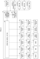
- Fig. 2 is a block diagram illustrating the swivel work machine 1.
- the control device 8 is connected with the operation device 7, the swivel motor 21, the traveling motor 22, the swing cylinder 112, the boom cylinder 122, the arm cylinder 132, and the bucket cylinder 142. Further, the control device 8 is connected with the operator seat IMU30-1, the boom IMU30-2, the arm IMU30-3, and the bucket IMU30-4.
- the control device 8 includes a first operation detection section (detection section) 81, an operation control section 82, and the IMU instruction section (output section) 83.
- the first operation detection section 81 is a detection section configured to detect an operation of causing the swivel section 2 to move.
- the first operation detection section 81 also detects, as the operation of causing the swivel section 2 to move, an operation of causing the swivel section 2 to move with respect to the ground by causing the traveling device 3 to travel. This makes it possible to, even when the swivel section 2 is configured to be caused to travel by the traveling device 3, allow the inertial sensors 30 to appropriately calculate the posture angles in accordance with the movement during the traveling.
- the first operation detection section 81 is connected with the operation device 7 and is configured to, on the basis of the operation performed on the operation device 7, detect an operation of causing the swivel section 2 to move.
- the first operation detection section 81 detects a traveling operation, a swivel operation, a swing operation, a boom operation, an arm operation, and a bucket operation on the basis of the operation levers. When the operation levers have been returned to their respective neutral positions, the first operation detection section 81 detects that the operations are not performed, i.e., that the swivel section 2 is stationary (detects no operation of causing movement).
- the operation control section 82 is configured to drive operation targets, that is, the traveling motor 22, the swivel motor 21, the swing cylinder 112, the boom cylinder 122, the arm cylinder 132, and the bucket cylinder 142 on the basis of signals indicative of operations inputted from the first operation detection section 81.
- the hydraulic pressures supplied to the traveling motor 22, the swivel motor 21, the swing cylinder 112, the boom cylinder 122, the arm cylinder 132, and the bucket cylinder 142 are controlled by proportional solenoid valves V1 to V6, respectively.
- the operation control section 82 controls these proportional solenoid valves V1 to V6.
- the IMU instruction section 83 is an output section configured to, in a case where the first operation detection section 81 has detected an operation of causing the swivel section 2 to move, output signals corresponding to the operation, to the inertial sensors 30.
- the IMU instruction section 83 outputs such a signal(s) corresponding to the operation, to an inertial sensor(s) 30 disposed at a position(s) at which the calculation of the posture angle(s) is affected by the movement of the swivel section 2 caused by the operation detected, among the plurality of inertial sensors 30 disposed in the swivel work machine 1.
- the first operation detection section 81 a signal indicative of a content of an operation that the operation device 7 has instructed the swivel section 2 to perform is inputted.
- the operation device 7 accepts an operation of causing the swivel section 2 to move.
- the first operation detection section 81 detects the operation of causing the swivel section 2 to move, from the operation device 7, that is, from a signal inputted from the operation device 7. According to the above configuration, since the first operation detection section 81 detects the operation of causing the swivel section 2 to move, from the operation performed on the operation device 7, it is possible to easily detect the movement of the swivel section 2.
- the first operation detection section 81 Upon receiving an instruction for traveling from the operation levers, the first operation detection section 81 outputs, to the IMU instruction section 83, a signal indicative of the instruction for the traveling operation. Similarly, upon receiving an instruction for swiveling from the operation levers, the first operation detection section 81 outputs, to the IMU instruction section 83, a signal indicative of the instruction for the swivel operation.
- the swing operation of causing the swing device 11 to move the boom operation of causing the boom device 12 to move, the arm operation of causing the arm device 13 to move, and the bucket operation of causing the bucket device 14 to move.
- the first operation detection section 81 detects that the swivel section 2 is stationary (detects no operation of causing movement).
- the IMU instruction section 83 is an output section configured to, in a case where an operation of causing the swivel section 2 to move has been detected, output signals corresponding to the operation, to the inertial sensors 30.
- the IMU instruction section 83 outputs the signal(s) corresponding to the operation, to an inertial sensor(s) 30 disposed at a position(s) at which the calculation of the posture angle(s) is affected by the movement of the swivel section 2 caused by the operation detected, among the plurality of inertial sensors 30 disposed in the swivel work machine 1.
- the IMU instruction section 83 does not receive, from the first operation detection section 81, a signal indicative of detection of an operation of causing the swivel section 2 to move (such as the traveling operation, the swivel operation, the swing operation, the boom operation, the arm operation, and the bucket operation), the IMU instruction section 83 outputs, to the inertial sensors 30, signals each instructing that a default weighting coefficient (a predetermined ratio) be used.
- a default weighting coefficient a predetermined ratio
- the IMU instruction section 83 Upon receiving, from the first operation detection section 81, a signal indicative of detection of an operation of causing the swivel section 2 to move, the IMU instruction section 83 outputs a signal(s) corresponding to the detected operation for the swivel section 2, to an inertial sensor(s) 30 affected by the movement of the swivel section 2.
- the "signal corresponding to the operation for the swivel section 2" refers to, for example, a signal instructing that a proportion of the angular-velocity component used for calculating the posture angle be increased to be higher than a predetermined proportion of the angular-velocity component used in a case where the operation has not been detected.
- the IMU instruction section 83 may also transmit, to the inertial sensor 30, a signal indicative of a weighting coefficient having a higher proportion of the acceleration component used for calculating the posture angle than that of the default weighting coefficient.
- a target to which a signal corresponding to an operation detected is to be outputted is an inertial sensor 30 disposed at a position at which a decrease in accuracy of the acceleration component is caused by detection of a disturbance acceleration resulting from the movement corresponding to the operation detected.
- the IMU instruction section 83 outputs signals corresponding to the operation, to the inertial sensors 30 (the operator seat IMU30-1, the boom IMU30-2, the arm IMU30-3, and the bucket IMU30-4) each disposed on the corresponding one of the machine body 4 and the plurality of movable sections of the work device 5.
- the IMU instruction section 83 outputs signals corresponding to the operation, to (i) the inertial sensor 30 that is disposed on the movable section to be caused to move and (ii) the inertial sensor(s) 30 that is (are) disposed on the movable section(s) located closer to a tip of the work device 5 than the movable section to be caused to move.
- the signals are outputted to the boom IMU30-2, the arm IMU30-3, and the bucket IMU30-4.
- the signals are outputted to the arm IMU30-3 and the bucket IMU30-4.
- the signal is outputted to the bucket IMU30-4.
- Fig. 3 is a diagram illustrating an aspect of operation contents and variations of the weighting which the IMU instruction section 83 instructs the inertial sensors 30 to perform.
- the reference number 301 indicates a diagram for the operator seat IMU30-1
- the reference number 302 indicates a diagram for the boom IMU30-2
- the reference number 303 indicates a diagram for the arm IMU30-3
- the reference number 304 indicates a diagram for the bucket IMU30-4.
- weighting coefficients are indicated by alphabets A to H.
- the alphabet A indicates a default weighting coefficient of each of the inertial sensors 30.
- the proportion of the acceleration component is higher than that of the angular-velocity component.
- the proportion of the acceleration component is represented by A>B>C>D>E>F>G>H. Accordingly, the proportion of the angular-velocity component increases, from the default, in the following order: A, B, C, D, E, F, G, H.
- the alphabet H indicates that the angular-velocity component accounts for almost all the proportion of the acceleration component and the angular-velocity component.
- the coefficients are A, and accordingly, the inertial sensors 30 use the default weighting coefficient.
- the state where the lever operations are minimum may also include a state where the traveling device 3, the swivel section 2, and the movable sections of the work device 5 each hardly move, as well as the state where the operation levers are set at their respective neutral positions.
- the proportion of the angular-velocity component used is increased, and the inertial sensor 30 calculates the posture angle with use of the increased proportion of the angular-velocity component.
- the traveling of the swivel work machine 1 has the same impact on all the inertial sensors 30. Therefore, with respect to the traveling operation, the coefficients F are set for all the inertial sensors 30.
- the proportion of the angular-velocity component used is set to be higher for the arm IMU30-3 and the bucket IMU30-4 than for the boom IMU30-2 and to be higher for the boom IMU30-2 than for the operator seat IMU30-1.
- the movement of the swing operation is slower than that of the traveling operation, that of the swivel operation, that of the boom operation of the work device 5, and that of the arm operation of the work device 5 and thus has less impact on the inertial sensors 30.
- a lower proportion of the angular-velocity component used is set.
- the proportion of the angular-velocity component used is set to be higher for the bucket IMU30-4 located farthest from an axis of the swinging than for the boom IMU30-2 located close to the axis of the swinging.
- weightings for the operations for the movable sections themselves on which the boom IMU30-2, the arm IMU30-3, and the bucket IMU30-4 are disposed are determined in accordance with shifts of the boom IMU30-2, the arm IMU30-3, and the bucket IMU30-4 from the corresponding shafts of the movable sections.
- a centrifugal force applied to the boom IMU30-2 mounted on the boom 121 is proportional to a distance between the boom IMU30-2 and the horizontal shaft 123 which extends in a left-and-right direction and which supports the boom 121 so as to make the boom 121 swingable (rotatable).
- the boom IMU30-2, the arm IMU30-3, and the bucket IMU30-4 are mounted at positions slightly distant from the corresponding shafts, and thus the proportions of the angular-velocity components used are low.
- the coefficients may be set to A.
- Fig. 4 is a flowchart showing a process, performed by the control device 8, for switching the weighting for each of the inertial sensors 30.
- the control device 8 always detects, from a signal from the operation device 7, whether an instruction for an operation of causing the swivel section 2 to move has been provided (S1). In a case where the determination in S1 is NO, that is, in a case where the swivel section 2 is in a stationary state, the control device 8 instructs all the inertial sensors 30 to use the default weighting coefficients (S2). In a case where the determination in S 1 is YES, that is, an operation of causing the swivel section 2 to move has been detected, the control device 8 instructs, to change the default weighting coefficient to the one corresponding to the operation detected, a predetermined inertial sensor 30 determined depending on the operation detected (S3).
- the "predetermined inertial sensor 30 determined depending on the operation detected” refers to a predetermined inertial sensor 30 disposed at a position at which a decrease in accuracy of the acceleration component is caused by detection of a disturbance acceleration resulting from the movement of the swivel section 2, as described above.
- the control device 8 After having instructed that the weighting coefficient be changed, the control device 8 always detects whether the operation of causing the swivel section 2 to move has been completed (S4). In a case where the determination in S4 is NO, that is, in a case where the operation of causing the swivel section 2 to move continues, the process returns to S3, and the control device 8 continues to instruct the predetermined inertial sensor 30 to change the default weighting coefficient (S3). In a case where the determination at S4 is YES, that is, in a case where the operation of causing the swivel section 2 to move is completed, and the swivel section 2 is in a stationary state, the control device 8 causes the process to return to S 1. Then, until the determination in S1 is made to be YES again, the control device 8 instructs all the inertial sensors 30 to use the default weighting coefficients (S2).
- the swivel work machine 1 having the above configuration enables notifying each of the inertial sensors 30 disposed on the swivel section 2 of movement of the swivel section 2 on which the inertial sensor 30 is disposed.
- the inertial sensors 30 make it possible to appropriately calculate the posture angles in accordance with a state of the movement of the swivel section 2.
- the inertial sensors 30 are caused to mainly use the angular-velocity components, which are not affected by the disturbance acceleration. Then, when the swivel section 2 is in a stationary state in which the swivel section 2 does not move, the inertial sensors 30 are caused to calculate the posture angles mainly with use of the acceleration components again. This makes it possible to maintain the accuracy of the detection in the stationary state without decreasing the accuracy even when the inertial sensors 30 are caused to perform the calculation with use of increased proportions of the angular-velocity components in which cumulative errors increase over time due to angular-velocity integration.
- the inertial sensors are each disposed on the corresponding one of the machine body 4 and the plurality of movable sections of the work device 5, it is possible to calculate each of the posture angles of the machine body 4 and the plurality of movable sections of the work device 5.
- Calculation of the posture angles of the work device 5 is affected by the movement of the machine body 4 even when the work device 5 does not move.
- a position to which the machine body 4 is mounted is an upstream side
- a movable section located closer to a downstream side is affected, even when the movable section itself does not move, by the movement of a movable section(s) located closer to the upstream side.
- the movement of the machine body 4 is notified to the inertial sensors 30 disposed on the work device 5, and the movement of a movable section located closer to the upstream side is notified to the inertial sensor(s) 30 of a movable section(s) located closer to the downstream side.
- a swivel work machine 1A of the present embodiment differs from the swivel work machine 1 of Embodiment 1 in the signals corresponding to the operation for the swivel section 2 which signals are outputted from the IMU instruction section 83 to the plurality of inertial sensors 30.
- the swivel work machine 1A of the present embodiment increases the proportion of the angular-velocity component used for calculating the posture angle to be higher than a predetermined proportion used in a case where an operation is not detected.
- the swivel work machine 1A of the present embodiment is further configured to instruct the inertial sensors 30 to continuously increase a proportion of the angular-velocity component, in accordance with an amount by which the operation device 7 is operated.
- the swivel work machine 1A of the present embodiment differs from the swivel work machine 1 of the Embodiment 1.
- the first operation detection section 81 detects, from a signal inputted from the operation device 7, amounts by which the operation levers are operated (amounts by which the operation levers move or amounts by which the positions of the operation levers change) and outputs, to the IMU instruction section 83, the detected operation amounts of the operation levers.
- the IMU instruction section 83 instructs the plurality of inertial sensors 30 to continuously increase, in accordance with the inputted operation amounts of the operation device 7, the proportions of the angular-velocity components used for calculating the posture angles to be higher than the predetermined proportion used in a case where any operation is not detected.
- the coefficients A are set for the minimum lever operations
- the coefficients F are set for the maximum lever operations.
- the weighting coefficients are continuously increased in accordance with the operation amounts of the operation levers, from the coefficients A to the coefficients F.
- the proportion of the angular-velocity component is increased in accordance with the operation amount of the operation device. This makes it possible to further reduce a sum total of the error resulting from the disturbance acceleration and the cumulative error resulting from the angular-velocity integration.
- employed in the present embodiment is a configuration in which the proportion of the angular-velocity component is increased in a continuous manner in accordance with the operation amount of the operation device 7.
- employed in the present embodiment may be a configuration in which the proportion of the angular-velocity component is increased in a stepwise manner in accordance with the operation amount of the operation device 7. That is, the above expression "in a continuous manner” can be replaced with "in a stepwise manner".
- a swivel work machine 1B of the present embodiment differs from the swivel work machine 1 of Embodiment 1 and the swivel work machine 1A of Embodiment 2 in a component that notifies the IMU instruction section 83 of the detection of an operation of causing the swivel section 2 to move.
- Fig. 5 is a block diagram illustrating the swivel work machine 1B.
- the swivel section 2 moves with use of the hydraulic actuators driven.
- a second operation detection section 9 which is a detection section, detects an operation of causing the swivel section 2 to move, from signals for controlling the hydraulic pressures supplied to the hydraulic actuators.
- the second operation detection section 9 detects the operation of causing the swivel section 2 to move, on the basis of control signals outputted from the operation control section 82 to the proportional solenoid valves V1 to V6.
- the IMU instruction section 83 outputs signals corresponding to the operation, to the inertial sensors 30.
- a swivel work machine 1C of the present embodiment includes a control device 8C instead of the control device 8 in each of the swivel work machines 1, 1A, and 1B of Embodiments 1, 2, and 3 respectively and includes control valves V11 to V16 instead of the operation control section 82 and the proportional solenoid valves V1 to V6 in each of the swivel work machines 1, 1A, and 1B.
- Fig. 6 is a block diagram illustrating the swivel work machine 1C.
- the operation device 7 is connected with the traveling motor 22 via the control valve V11 and is connected with the swivel motor 21 via the control valve V12.
- the operation device 7 is connected with the swing cylinder 112, the boom cylinder 122, the arm cylinder 132, and the bucket cylinder 142 via the control valves V13 to V16, respectively.
- the traveling motor 22, the swivel motor 21, the swing cylinder 112, the boom cylinder 122, the arm cylinder 132, and the bucket cylinder 142 are controlled by the control valves V11 to V16, respectively.
- Each of the control valves V11 to V16 is constituted by a direct-acting spool-type switching valve and a pilot-operated switching valve subjected to a switching operation with use of a pilot pressure.
- control valves V11 to V16 are operated in proportion to operation amounts of the operation levers of the operation device 7 for operating the control valves V11 to V16 and are configured to supply, to the corresponding control-target hydraulic actuators, pressurized oil in amounts proportional to amounts by which the control valves V11 to V16 are operated.
- a third operation detection section 10 detects the operation of causing the swivel section 2 to move.
- the third operation detection section 10 detects the operation of causing the swivel section 2 to move, on the basis of pilot pressures applied to the control valves V11 to V16.
- the IMU instruction section 83 outputs signals corresponding to the operation, to the inertial sensors 30.
- each control device 8 and 8C can be realized by a program for causing a computer to function as the device.
- the program causes the computer to function as control blocks of the device.
- the device includes, as hardware for executing the program, a computer including at least one control device (for example, a processor) and at least one storage device (for example, a memory).
- a control device for example, a processor
- at least one storage device for example, a memory
- the program can be stored in one or more non-transitory computer-readable storage media.
- the one or more storage media may be included in the device or may not be included in the device. In the latter case, the program can be supplied to or made available to the device via any wired or wireless transmission medium.
- control blocks can also be realized by a logic circuit.
- a logic circuit for example, an integrated circuit in which a logic circuit functioning as the control blocks is formed is included in the scope of the present invention.
- the functions of the control blocks can also be realized, for example, by a quantum computer.
- AI artificial intelligence
- AI may be operated in the control device or another device (e.g., an edge computer or a cloud server).
- a swivel work machine in accordance with an aspect of the present invention includes: a swivel section; at least one inertial sensor which is disposed on the swivel section and which is configured to calculate a posture angle of the swivel section on the basis of an angular velocity and an acceleration; a detection section configured to detect an operation of causing the swivel section to move; and an output section configured to, in a case where the operation of causing the swivel section to move has been detected, output a signal corresponding to the operation, to the at least one inertial sensor.
- a swivel work machine in accordance with an aspect of the present invention may be configured such that the signal corresponding to the operation is a signal instructing that a proportion of an angular-velocity component used for calculating the posture angle be increased to be higher than a predetermined proportion of the angular-velocity component used in a case where the operation is not detected.
- a swivel work machine in accordance with an aspect of the present invention may include a traveling device on which the swivel section is installed so as to be able to swivel and may be configured such that the detection section also detects, as the operation of causing the swivel section to move, an operation of causing the traveling device to travel.
- the inertial sensor even in the configuration in which the swivel section is caused to travel by the traveling device, it is possible to cause the inertial sensor to appropriately calculate the posture angle in accordance with the movement during the traveling.
- a swivel work machine in accordance with an aspect of the present invention may include an operation device configured to accept the operation of causing the swivel section to move and may be configured such that the detection section detects, on the basis of the operation performed on the operation device, the operation of causing the swivel section to move.
- a swivel work machine in accordance with an aspect of the present invention may be configured such that the signal corresponding to the operation is a signal instructing that a proportion of an angular-velocity component used for calculating the posture angle be increased to be higher than a predetermined proportion of the angular-velocity component used in a case where the operation is not detected, and a proportion of the angular-velocity component be increased in a continuous manner or in a stepwise manner in accordance with an amount by which the operation device is operated.
- the proportion of the angular-velocity component is increased in a continuous manner or in a stepwise manner in accordance with the operation amount of the operation device, it is possible to further reduce a sum total of an error resulting from a disturbance acceleration and a cumulative error resulting from the angular-velocity integration.
- a swivel work machine in accordance with an aspect of the present invention may be configured such that the swivel section moves with use of hydraulic actuators driven, and the detection section detects, from signals for controlling hydraulic pressures supplied to the hydraulic actuators, the operation of causing the swivel section to move.
- a swivel work machine in accordance with an aspect of the present invention may be configured such that the swivel section includes: a machine body configured to swivel; and a work device that is mounted to the machine body and that has a plurality of movable sections, the at least one inertial sensor includes a plurality of inertial sensors, the plurality of inertial sensors are each disposed on corresponding one of the machine body and the plurality of movable sections of the work device, and the output section is configured to: in a case where an operation of causing the machine body to move has been detected, output signals corresponding to the operation, to the plurality of inertial sensors each disposed on the corresponding one of the machine body and the plurality of movable sections of the work device; and in a case where an operation of causing one of the plurality of movable sections to move has been detected, output signals corresponding to the operation, to the inertial sensors disposed on the movable section to be caused to move and on at least one of the other
- the inertial sensors are each disposed on the corresponding one of the machine body and the plurality of movable sections of the work device, it is possible to calculate each of the posture angles of the machine body and the plurality of movable sections. Calculation of a posture angle of the work device is affected by the movement of the machine body even when the work device does not move. Similarly, assuming that, in the work device, a position to which the machine body is mounted is an upstream side, a movable section located closer to a downstream side is affected, even when the movable section itself does not move, by the movement of a movable section(s) located closer to the upstream side.
- the movement of the machine body is notified to the inertial sensors disposed in the work device, and the movement of a movable section located closer to the upstream side is notified to the inertial sensor(s) of a movable section(s) located closer to the downstream side.
- the present invention is not limited to the embodiments, but can be altered by a skilled person in the art within the scope of the claims.
- the present invention also encompasses, in its technical scope, any embodiment derived by combining technical means disclosed in differing embodiments.
Landscapes
- Engineering & Computer Science (AREA)
- Mining & Mineral Resources (AREA)
- Civil Engineering (AREA)
- General Engineering & Computer Science (AREA)
- Structural Engineering (AREA)
- Operation Control Of Excavators (AREA)
- Component Parts Of Construction Machinery (AREA)
Abstract
In order to accurately detect a posture angle of a swivel section even when a disturbance acceleration occurs due to the movement of the swivel section, a swivel work machine includes: a swivel section; at least one inertial sensor (30) that is disposed on the swivel section and that is configured to calculate a posture angle of the swivel section on the basis of an angular velocity and an acceleration; a first operation detection section as a detection section (81) configured to detect an operation of causing the swivel section to move; and an IMU instruction section as an output section (83) configured to, in a case where an operation of causing movement has been detected, output a signal corresponding to the operation, to the at least one inertial sensor.
Description
- The present invention relates to a swivel work machine including a swivel section, such as an excavator.
- Conventionally, a work machine has been known which is disclosed in Patent Literature 1 and which includes an inclination-angle detection section for detecting an inclination angle of a machine body of the work machine. The inclination-angle detection section includes: an acceleration sensor which is mounted to the machine body so as to cause an output from the acceleration sensor with respect to a gravitational acceleration to vary in accordance with the inclination angle of the machine body; and a conversion section for converting, into the inclination angle of the machine, the output from the acceleration sensor.
- In addition, conventionally, inertial sensors (inertial measurement units (IMUs)) have been widely used as posture detection sections for vehicles. Such an inertial sensor includes an acceleration sensor and an angular-velocity sensor. The inertial sensor is configured to measure an angular velocity of the machine body and an acceleration thereof to calculate, for example, a posture angle of the machine body and an azimuth thereof.
- [Patent Literature 1]
Japanese Patent No. 5297280 - However, unlike a typical vehicle, in the swivel work machine, a swivel section thereof swivels. Thus, an acceleration caused by the movement of the swivel section occurs. This acceleration is regarded as a disturbance acceleration and has an impact on the acceleration used to calculate the posture angle of the swivel work machine. The posture angle calculated by the inertial sensor therefore has an error.
- It is an object of an aspect of the present invention to achieve a swivel work machine that enables accurate detection of a posture angle of a swivel section of the swivel work machine even when a disturbance acceleration occurs due to movement of the swivel section.
- In order to solve the foregoing problem, a swivel work machine in accordance with an aspect of the present invention includes: a swivel section; at least one inertial sensor which is disposed on the swivel section and which is configured to calculate a posture angle of the swivel section on the basis of an angular velocity and an acceleration; a detection section configured to detect an operation of causing the swivel section to move; and an output section configured to, in a case where the operation of causing the swivel section to move has been detected, output a signal corresponding to the operation, to the at least one inertial sensor.
- An aspect of the present invention makes it possible to achieve a swivel work machine that enables accurate detection of a posture angle of a swivel section of the swivel work machine even when a disturbance acceleration occurs due to movement of the swivel section.
-
-
Fig. 1 is a side view schematically illustrating a swivel work machine in accordance with Embodiment 1 of the present invention. -
Fig. 2 is a block diagram illustrating the swivel work machine. -
Fig. 3 is a diagram illustrating an aspect of operation contents and variations of weighting which an IMU instruction section instructs inertial sensors to perform. -
Fig. 4 is a flowchart showing a process of switching the weighting for each of the inertial sensors, in a control device. -
Fig. 5 is a block diagram illustrating a swivel work machine in accordance withEmbodiment 3 of the present invention. -
Fig. 6 is a block diagram illustrating a swivel work machine in accordance withEmbodiment 4 of the present invention. - The following will describe an embodiment of the present invention with reference to drawings as appropriate.
-
Fig. 1 is a side view schematically illustrating a swivel work machine 1 in accordance with the present embodiment. In the present embodiment, an excavator is taken as an example of the swivel work machine 1. Note that the present invention also encompasses swivel work machines without traveling devices, such as crane machines. - As illustrated in
Fig. 1 , the swivel work machine 1 includes aswivel section 2 and atraveling device 3. Theswivel section 2 is supported on thetraveling device 3 so as to be able to swivel about an axis extending in an up-and-down direction. Theswivel section 2 is driven by aswivel motor 21. Thetraveling device 3 supports theswivel section 2 so as to enable theswivel section 2 to travel and is driven by a travelingmotor 22. Theswivel motor 21 and thetraveling motor 22 are each constituted by a hydraulic motor (hydraulic actuator). - The
swivel section 2 includes: amachine body 4 configured to swivel with respect to thetraveling device 3; aswing device 11; awork device 5; and the like. Themachine body 4 includes anoperator seat 6, anoperation device 7, acontrol device 8, an engine (not illustrated), a radiator (not illustrated), a fuel tank (not illustrated), a hydraulic fluid tank (not illustrated), a battery (not illustrated), and the like. Note that, in the present embodiment, front, rear, right, left, up, and down are defined with respect to an operator seated on theoperator seat 6. - The
operation device 7 includes a plurality of operation levers each of which accepts an operation of causing theswivel section 2 to move. Examples of such an operation include an operation of causing thetraveling device 3 to travel, an operation of causing theswivel section 2 to swivel, and operations of causing theswing device 11 and movable sections (aboom device 12, anarm device 13, and a bucket device 14) of thework device 5 to move. - The
control device 8 is configured to control parts of the swivel work machine 1, such as an engine. In addition, in the present embodiment, thecontrol device 8 is configured to detect an operation that the swivel work machine 1 is instructed to perform by theoperation device 7 and to, in a case where an operation of causing theswivel section 2 to move has been detected, output signals corresponding to the operation detected, toinertial sensors 30 disposed at predetermined positions of the swivel work machine 1. Theinertial sensors 30 will be described later. - The
swing device 11 is located at a front portion of themachine body 4, and thework device 5 is mounted on theswing device 11. Thework device 5 includes theboom device 12, thearm device 13, and thebucket device 14 which correspond to the plurality of movable sections. - Specifically, the
swing device 11 includes aswing bracket 111 and a swing cylinder 112 (seeFig. 2 ). Theswing bracket 111 is, so as to be swingable about an axis extending in an up-and-down direction, mounted on asupport bracket 20 provided to the front portion of themachine body 4 so as to protrude from the front portion. Theswing bracket 111 is driven by theswing cylinder 112. - The
boom device 12 includes aboom 121 and aboom cylinder 122. Theboom 121 has a base portion which is supported by an upper portion of theswing bracket 111 via ahorizontal shaft 123 extending in a left-and-right direction so as to make theboom 121 swingable (rotatable). Theboom cylinder 122 extends and contracts to cause theboom 121 to swing. - The
arm device 13 includes anarm 131 and anarm cylinder 132. Thearm 131 has a base end portion which is supported at a tip portion of theboom 121 via ahorizontal shaft 133 so as to make thearm 131 swingable. Thearm cylinder 132 extends and contracts to cause thearm 131 to swing. - The
bucket device 14 includes abucket 141 and abucket cylinder 142. Thebucket 141 is supported at a tip portion of thearm 131 via apivot shaft 143 so as to be swingable. Thebucket cylinder 142 is provided over alink mechanism 144 provided between thebucket 141 and the tip portion of thearm 131 and the base end portion of thearm 131 and extends and contracts to cause thebucket 141 to swing. - The
swing cylinder 112, theboom cylinder 122, thearm cylinder 132, and thebucket cylinder 142 are each constituted by a hydraulic cylinder (hydraulic actuator) that can extend and contract. - The swivel work machine 1 includes the inertial sensors (IMUs) 30 described above. The
inertial sensors 30 each include an acceleration sensor and an angular-velocity sensor and are each configured to measure an acceleration and an angular velocity of a member on which theinertial sensor 30 is disposed and to calculate a posture angle, an azimuth, a velocity, a position, and the like of the member on the basis of the acceleration and the angular velocity. - The
inertial sensors 30 each calculate "current angle + angular velocity × unit time" on the basis of the detection value from the angular-velocity sensor to obtain an angular-velocity component. In addition, theinertial sensors 30 each calculate "a direction of a gravitational acceleration" on the basis of the detection value from the acceleration sensor to obtain an acceleration component. - In a state where the
inertial sensors 30 are stationary (specifically, in a state where respective members on which theinertial sensors 30 are disposed are stationary), the acceleration components have no errors, whereas in a state where theinertial sensors 30 move (specifically, in a state where the respective members on which theinertial sensors 30 are disposed move), the acceleration components contain disturbance accelerations, resulting in errors. The angular-velocity components are not affected, even in a state where theinertial sensors 30 move, by the movement (disturbance). However, cumulative errors in the angular-velocity components increase over time due to angular-velocity integration. - Thus, the
inertial sensors 30 each calculate the posture angle with use of both the acceleration component and the angular-velocity component. The proportions of the angular-velocity component and the acceleration component used by each of theinertial sensors 30 is determined with use of a weighting coefficient. The weighting coefficient can be changed by each of theinertial sensors 30. In the present embodiment, theinertial sensors 30 each change the weighting coefficient in accordance with a signal outputted from an IMU instruction section (output section) 83 (described later) of thecontrol device 8. - In the present embodiment, the
inertial sensors 30 are individually disposed under theoperator seat 6 of themachine body 4 and on theboom 121, thearm 131, and thelink mechanism 144 in the plurality of movable sections of thework device 5. - Hereinafter, in a case where the
inertial sensors 30 need to be distinguished from each other depending on members on which theinertial sensors 30 are disposed, theinertial sensor 30 disposed on the machine body 4 (in the present embodiment, under the operator seat 6) is referred to as an operator seat IMU30-1, theinertial sensor 30 disposed on theboom 121 is referred to as a boom IMU30-2, theinertial sensor 30 disposed on thearm 131 is referred to as an arm IMU30-3, and theinertial sensor 30 disposed on thelink mechanism 144 is referred to as a bucket IMU30-4. - The operator seat IMU30-1 is configured to measure a posture of the
machine body 4 in the swivel work machine 1. The boom IMU30-2, the arm IMU30-3, and the bucket IMU30-4 are each configured to measure an angle of thework device 5. The boom IMU30-2 and the arm IMU30-3 are each mounted on a side surface of the corresponding member. The bucket IMU30-4 is mounted on thelink mechanism 144. -
Fig. 2 is a block diagram illustrating the swivel work machine 1. As illustrated inFig. 2 , thecontrol device 8 is connected with theoperation device 7, theswivel motor 21, the travelingmotor 22, theswing cylinder 112, theboom cylinder 122, thearm cylinder 132, and thebucket cylinder 142. Further, thecontrol device 8 is connected with the operator seat IMU30-1, the boom IMU30-2, the arm IMU30-3, and the bucket IMU30-4. Thecontrol device 8 includes a first operation detection section (detection section) 81, anoperation control section 82, and the IMU instruction section (output section) 83. - The first
operation detection section 81 is a detection section configured to detect an operation of causing theswivel section 2 to move. The firstoperation detection section 81 also detects, as the operation of causing theswivel section 2 to move, an operation of causing theswivel section 2 to move with respect to the ground by causing the travelingdevice 3 to travel. This makes it possible to, even when theswivel section 2 is configured to be caused to travel by the travelingdevice 3, allow theinertial sensors 30 to appropriately calculate the posture angles in accordance with the movement during the traveling. - The first
operation detection section 81 is connected with theoperation device 7 and is configured to, on the basis of the operation performed on theoperation device 7, detect an operation of causing theswivel section 2 to move. - The first
operation detection section 81 detects a traveling operation, a swivel operation, a swing operation, a boom operation, an arm operation, and a bucket operation on the basis of the operation levers. When the operation levers have been returned to their respective neutral positions, the firstoperation detection section 81 detects that the operations are not performed, i.e., that theswivel section 2 is stationary (detects no operation of causing movement). - The
operation control section 82 is configured to drive operation targets, that is, the travelingmotor 22, theswivel motor 21, theswing cylinder 112, theboom cylinder 122, thearm cylinder 132, and thebucket cylinder 142 on the basis of signals indicative of operations inputted from the firstoperation detection section 81. In the present embodiment, the hydraulic pressures supplied to the travelingmotor 22, theswivel motor 21, theswing cylinder 112, theboom cylinder 122, thearm cylinder 132, and thebucket cylinder 142 are controlled by proportional solenoid valves V1 to V6, respectively. Specifically, theoperation control section 82 controls these proportional solenoid valves V1 to V6. - The
IMU instruction section 83 is an output section configured to, in a case where the firstoperation detection section 81 has detected an operation of causing theswivel section 2 to move, output signals corresponding to the operation, to theinertial sensors 30. TheIMU instruction section 83 outputs such a signal(s) corresponding to the operation, to an inertial sensor(s) 30 disposed at a position(s) at which the calculation of the posture angle(s) is affected by the movement of theswivel section 2 caused by the operation detected, among the plurality ofinertial sensors 30 disposed in the swivel work machine 1. - Specifically, to the first
operation detection section 81, a signal indicative of a content of an operation that theoperation device 7 has instructed theswivel section 2 to perform is inputted. Theoperation device 7 accepts an operation of causing theswivel section 2 to move. The firstoperation detection section 81 detects the operation of causing theswivel section 2 to move, from theoperation device 7, that is, from a signal inputted from theoperation device 7. According to the above configuration, since the firstoperation detection section 81 detects the operation of causing theswivel section 2 to move, from the operation performed on theoperation device 7, it is possible to easily detect the movement of theswivel section 2. - Upon receiving an instruction for traveling from the operation levers, the first
operation detection section 81 outputs, to theIMU instruction section 83, a signal indicative of the instruction for the traveling operation. Similarly, upon receiving an instruction for swiveling from the operation levers, the firstoperation detection section 81 outputs, to theIMU instruction section 83, a signal indicative of the instruction for the swivel operation. The same applies to the swing operation of causing theswing device 11 to move, the boom operation of causing theboom device 12 to move, the arm operation of causing thearm device 13 to move, and the bucket operation of causing thebucket device 14 to move. When the operation levers have been returned to their respective neutral positions, the firstoperation detection section 81 detects that theswivel section 2 is stationary (detects no operation of causing movement). - The
IMU instruction section 83 is an output section configured to, in a case where an operation of causing theswivel section 2 to move has been detected, output signals corresponding to the operation, to theinertial sensors 30. TheIMU instruction section 83 outputs the signal(s) corresponding to the operation, to an inertial sensor(s) 30 disposed at a position(s) at which the calculation of the posture angle(s) is affected by the movement of theswivel section 2 caused by the operation detected, among the plurality ofinertial sensors 30 disposed in the swivel work machine 1. - In a case where the
IMU instruction section 83 does not receive, from the firstoperation detection section 81, a signal indicative of detection of an operation of causing theswivel section 2 to move (such as the traveling operation, the swivel operation, the swing operation, the boom operation, the arm operation, and the bucket operation), theIMU instruction section 83 outputs, to theinertial sensors 30, signals each instructing that a default weighting coefficient (a predetermined ratio) be used. - Upon receiving, from the first
operation detection section 81, a signal indicative of detection of an operation of causing theswivel section 2 to move, theIMU instruction section 83 outputs a signal(s) corresponding to the detected operation for theswivel section 2, to an inertial sensor(s) 30 affected by the movement of theswivel section 2. - The "signal corresponding to the operation for the
swivel section 2" refers to, for example, a signal instructing that a proportion of the angular-velocity component used for calculating the posture angle be increased to be higher than a predetermined proportion of the angular-velocity component used in a case where the operation has not been detected. TheIMU instruction section 83 may also transmit, to theinertial sensor 30, a signal indicative of a weighting coefficient having a higher proportion of the acceleration component used for calculating the posture angle than that of the default weighting coefficient. - Here, a target to which a signal corresponding to an operation detected is to be outputted is an
inertial sensor 30 disposed at a position at which a decrease in accuracy of the acceleration component is caused by detection of a disturbance acceleration resulting from the movement corresponding to the operation detected. Specifically, upon receiving, from the firstoperation detection section 81, a signal indicative of detection of the traveling operation or the swivel operation, which is an operation of causing themachine body 4 to move, theIMU instruction section 83 outputs signals corresponding to the operation, to the inertial sensors 30 (the operator seat IMU30-1, the boom IMU30-2, the arm IMU30-3, and the bucket IMU30-4) each disposed on the corresponding one of themachine body 4 and the plurality of movable sections of thework device 5. - In a case where an operation detected is an operation of causing one of the plurality of movable sections, including the
swing device 11, to move, that is, in a case where an operation detected is the swing operation, the boom operation, the arm operation, or the bucket operation, theIMU instruction section 83 outputs signals corresponding to the operation, to (i) theinertial sensor 30 that is disposed on the movable section to be caused to move and (ii) the inertial sensor(s) 30 that is (are) disposed on the movable section(s) located closer to a tip of thework device 5 than the movable section to be caused to move. In a case where the operation detected is an operation of causing theswing device 11 or theboom device 12 to move, the signals are outputted to the boom IMU30-2, the arm IMU30-3, and the bucket IMU30-4. In a case where the operation detected is an operation of causing thearm device 13 to move, the signals are outputted to the arm IMU30-3 and the bucket IMU30-4. In a case where the operation detected is an operation of causing thebucket device 14 to move, the signal is outputted to the bucket IMU30-4. -
Fig. 3 is a diagram illustrating an aspect of operation contents and variations of the weighting which theIMU instruction section 83 instructs theinertial sensors 30 to perform. InFig. 3 , thereference number 301 indicates a diagram for the operator seat IMU30-1, thereference number 302 indicates a diagram for the boom IMU30-2, thereference number 303 indicates a diagram for the arm IMU30-3, and the reference number 304 indicates a diagram for the bucket IMU30-4. - As to the
reference numbers 301 to 304 inFig. 3 , weighting coefficients are indicated by alphabets A to H. The alphabet A indicates a default weighting coefficient of each of theinertial sensors 30. In the default weighting coefficient, the proportion of the acceleration component is higher than that of the angular-velocity component. The proportion of the acceleration component is represented by A>B>C>D>E>F>G>H. Accordingly, the proportion of the angular-velocity component increases, from the default, in the following order: A, B, C, D, E, F, G, H. The alphabet H indicates that the angular-velocity component accounts for almost all the proportion of the acceleration component and the angular-velocity component. - As illustrated in
Fig. 3 , in all the operations, that is, the traveling operation, the swivel operation, the swing operation, the boom operation, the arm operation, and the bucket operation, in a case where the lever operations are minimum, that is, in a case where the operation levers are set at their respective neutral positions, the coefficients are A, and accordingly, theinertial sensors 30 use the default weighting coefficient. Note that the state where the lever operations are minimum may also include a state where the travelingdevice 3, theswivel section 2, and the movable sections of thework device 5 each hardly move, as well as the state where the operation levers are set at their respective neutral positions. - When the maximum lever operation has been detected, that is, when an operation of causing the maximum movement has been detected, the proportion of the angular-velocity component used is increased, and the
inertial sensor 30 calculates the posture angle with use of the increased proportion of the angular-velocity component. The traveling of the swivel work machine 1 has the same impact on all theinertial sensors 30. Therefore, with respect to the traveling operation, the coefficients F are set for all theinertial sensors 30. - In swiveling of the
swivel section 2, aninertial sensor 30 located farther from an axis of the swiveling is more affected by the centrifugal force. Therefore, with respect to the swivel operation, the proportion of the angular-velocity component used is set to be higher for the arm IMU30-3 and the bucket IMU30-4 than for the boom IMU30-2 and to be higher for the boom IMU30-2 than for the operator seat IMU30-1. - The movement of the swing operation is slower than that of the traveling operation, that of the swivel operation, that of the boom operation of the
work device 5, and that of the arm operation of thework device 5 and thus has less impact on theinertial sensors 30. Thus, with respect to the swing operation, a lower proportion of the angular-velocity component used is set. Also in this case, similarly as the swivel operation, the proportion of the angular-velocity component used is set to be higher for the bucket IMU30-4 located farthest from an axis of the swinging than for the boom IMU30-2 located close to the axis of the swinging. - Further, weightings for the operations for the movable sections themselves on which the boom IMU30-2, the arm IMU30-3, and the bucket IMU30-4 are disposed are determined in accordance with shifts of the boom IMU30-2, the arm IMU30-3, and the bucket IMU30-4 from the corresponding shafts of the movable sections. For example, in a case of the
boom device 12, a centrifugal force applied to the boom IMU30-2 mounted on theboom 121 is proportional to a distance between the boom IMU30-2 and thehorizontal shaft 123 which extends in a left-and-right direction and which supports theboom 121 so as to make theboom 121 swingable (rotatable). Note, however, that, in the present embodiment, the boom IMU30-2, the arm IMU30-3, and the bucket IMU30-4 are mounted at positions slightly distant from the corresponding shafts, and thus the proportions of the angular-velocity components used are low. In a case where the boom IMU30-2, the arm IMU30-3, and the bucket IMU30-4 are mounted in the vicinities of the corresponding shafts of the movable sections, the coefficients may be set to A. -
Fig. 4 is a flowchart showing a process, performed by thecontrol device 8, for switching the weighting for each of theinertial sensors 30. - As illustrated in
Fig. 4 , thecontrol device 8 always detects, from a signal from theoperation device 7, whether an instruction for an operation of causing theswivel section 2 to move has been provided (S1). In a case where the determination in S1 is NO, that is, in a case where theswivel section 2 is in a stationary state, thecontrol device 8 instructs all theinertial sensors 30 to use the default weighting coefficients (S2). In a case where the determination in S 1 is YES, that is, an operation of causing theswivel section 2 to move has been detected, thecontrol device 8 instructs, to change the default weighting coefficient to the one corresponding to the operation detected, a predeterminedinertial sensor 30 determined depending on the operation detected (S3). The "predeterminedinertial sensor 30 determined depending on the operation detected" refers to a predeterminedinertial sensor 30 disposed at a position at which a decrease in accuracy of the acceleration component is caused by detection of a disturbance acceleration resulting from the movement of theswivel section 2, as described above. - After having instructed that the weighting coefficient be changed, the
control device 8 always detects whether the operation of causing theswivel section 2 to move has been completed (S4). In a case where the determination in S4 is NO, that is, in a case where the operation of causing theswivel section 2 to move continues, the process returns to S3, and thecontrol device 8 continues to instruct the predeterminedinertial sensor 30 to change the default weighting coefficient (S3). In a case where the determination at S4 is YES, that is, in a case where the operation of causing theswivel section 2 to move is completed, and theswivel section 2 is in a stationary state, thecontrol device 8 causes the process to return to S 1. Then, until the determination in S1 is made to be YES again, thecontrol device 8 instructs all theinertial sensors 30 to use the default weighting coefficients (S2). - As described above, the swivel work machine 1 having the above configuration enables notifying each of the
inertial sensors 30 disposed on theswivel section 2 of movement of theswivel section 2 on which theinertial sensor 30 is disposed. Thus, theinertial sensors 30 make it possible to appropriately calculate the posture angles in accordance with a state of the movement of theswivel section 2. - Specifically, when the
swivel section 2 in which a disturbance acceleration causes a large error in calculation of the posture angle is in a state of being moved, theinertial sensors 30 are caused to mainly use the angular-velocity components, which are not affected by the disturbance acceleration. Then, when theswivel section 2 is in a stationary state in which theswivel section 2 does not move, theinertial sensors 30 are caused to calculate the posture angles mainly with use of the acceleration components again. This makes it possible to maintain the accuracy of the detection in the stationary state without decreasing the accuracy even when theinertial sensors 30 are caused to perform the calculation with use of increased proportions of the angular-velocity components in which cumulative errors increase over time due to angular-velocity integration. - Further, according to the above configuration, since the inertial sensors are each disposed on the corresponding one of the
machine body 4 and the plurality of movable sections of thework device 5, it is possible to calculate each of the posture angles of themachine body 4 and the plurality of movable sections of thework device 5. Calculation of the posture angles of thework device 5 is affected by the movement of themachine body 4 even when thework device 5 does not move. Similarly, assuming that, in thework device 5, a position to which themachine body 4 is mounted is an upstream side, a movable section located closer to a downstream side is affected, even when the movable section itself does not move, by the movement of a movable section(s) located closer to the upstream side. In the above configuration, the movement of themachine body 4 is notified to theinertial sensors 30 disposed on thework device 5, and the movement of a movable section located closer to the upstream side is notified to the inertial sensor(s) 30 of a movable section(s) located closer to the downstream side. This makes it possible to cause the plurality ofinertial sensors 30 disposed on thework device 5 to appropriately calculate the posture angles. - The following will describe another embodiment of the present invention. For convenience, members having identical functions to those of the foregoing embodiments are given identical reference signs, and their descriptions will be omitted.
- A swivel work machine 1A of the present embodiment differs from the swivel work machine 1 of Embodiment 1 in the signals corresponding to the operation for the
swivel section 2 which signals are outputted from theIMU instruction section 83 to the plurality ofinertial sensors 30. - As in the case of the swivel work machine 1 of Embodiment 1, the swivel work machine 1A of the present embodiment increases the proportion of the angular-velocity component used for calculating the posture angle to be higher than a predetermined proportion used in a case where an operation is not detected. The swivel work machine 1A of the present embodiment is further configured to instruct the
inertial sensors 30 to continuously increase a proportion of the angular-velocity component, in accordance with an amount by which theoperation device 7 is operated. In this respect, the swivel work machine 1A of the present embodiment differs from the swivel work machine 1 of the Embodiment 1. - Specifically, the first
operation detection section 81 detects, from a signal inputted from theoperation device 7, amounts by which the operation levers are operated (amounts by which the operation levers move or amounts by which the positions of the operation levers change) and outputs, to theIMU instruction section 83, the detected operation amounts of the operation levers. TheIMU instruction section 83 instructs the plurality ofinertial sensors 30 to continuously increase, in accordance with the inputted operation amounts of theoperation device 7, the proportions of the angular-velocity components used for calculating the posture angles to be higher than the predetermined proportion used in a case where any operation is not detected. - With reference to
Fig. 3 described above, the following will describe the increase of the proportions of the angular-velocity components in a continuous manner in accordance with the operation amounts of theoperation device 7. As illustrated inFig. 3 , with respect to the traveling operation and the swivel operation for the operator seat IMU30-1, the coefficients A are set for the minimum lever operations, and the coefficients F are set for the maximum lever operations. In this case, the weighting coefficients are continuously increased in accordance with the operation amounts of the operation levers, from the coefficients A to the coefficients F. - Thus, in a case where the angular-velocity components, which have small errors due to the movement, are mainly used when the swivel section moves, the proportion of the angular-velocity component is increased in accordance with the operation amount of the operation device. This makes it possible to further reduce a sum total of the error resulting from the disturbance acceleration and the cumulative error resulting from the angular-velocity integration.
- Note that employed in the present embodiment is a configuration in which the proportion of the angular-velocity component is increased in a continuous manner in accordance with the operation amount of the
operation device 7. Alternatively, employed in the present embodiment may be a configuration in which the proportion of the angular-velocity component is increased in a stepwise manner in accordance with the operation amount of theoperation device 7. That is, the above expression "in a continuous manner" can be replaced with "in a stepwise manner". - The following will describe another embodiment of the present invention. For convenience, members having identical functions to those of the foregoing embodiments are given identical reference signs, and their descriptions will be omitted.
- A swivel work machine 1B of the present embodiment differs from the swivel work machine 1 of Embodiment 1 and the swivel work machine 1A of
Embodiment 2 in a component that notifies theIMU instruction section 83 of the detection of an operation of causing theswivel section 2 to move. -
Fig. 5 is a block diagram illustrating the swivel work machine 1B. As described above, theswivel section 2 moves with use of the hydraulic actuators driven. Then, as illustrated inFig. 5 , in the swivel work machine 1B, a secondoperation detection section 9, which is a detection section, detects an operation of causing theswivel section 2 to move, from signals for controlling the hydraulic pressures supplied to the hydraulic actuators. Specifically, the secondoperation detection section 9 detects the operation of causing theswivel section 2 to move, on the basis of control signals outputted from theoperation control section 82 to the proportional solenoid valves V1 to V6. - In a case where the second
operation detection section 9 has detected the operation of causing theswivel section 2 to move, theIMU instruction section 83 outputs signals corresponding to the operation, to theinertial sensors 30. - As in the above configuration, it is also possible to detect the operation from the hydraulic pressures to the hydraulic actuators for causing the movable sections and the like to move in accordance with the operation, instead of detecting the operation directly from the operation performed on the
operation device 7. - The following will describe another embodiment of the present invention. For convenience, members having identical functions to those of the foregoing embodiments are given identical reference signs, and their descriptions will be omitted.
- A swivel work machine 1C of the present embodiment includes a
control device 8C instead of thecontrol device 8 in each of the swivel work machines 1, 1A, and 1B ofEmbodiments operation control section 82 and the proportional solenoid valves V1 to V6 in each of the swivel work machines 1, 1A, and 1B. -
Fig. 6 is a block diagram illustrating the swivel work machine 1C. As illustrated inFig. 6 , theoperation device 7 is connected with the travelingmotor 22 via the control valve V11 and is connected with theswivel motor 21 via the control valve V12. Similarly, theoperation device 7 is connected with theswing cylinder 112, theboom cylinder 122, thearm cylinder 132, and thebucket cylinder 142 via the control valves V13 to V16, respectively. - The traveling
motor 22, theswivel motor 21, theswing cylinder 112, theboom cylinder 122, thearm cylinder 132, and thebucket cylinder 142 are controlled by the control valves V11 to V16, respectively. Each of the control valves V11 to V16 is constituted by a direct-acting spool-type switching valve and a pilot-operated switching valve subjected to a switching operation with use of a pilot pressure. - The control valves V11 to V16 are operated in proportion to operation amounts of the operation levers of the
operation device 7 for operating the control valves V11 to V16 and are configured to supply, to the corresponding control-target hydraulic actuators, pressurized oil in amounts proportional to amounts by which the control valves V11 to V16 are operated. - In the swivel work machine 1C of the present embodiment, a third
operation detection section 10 detects the operation of causing theswivel section 2 to move. The thirdoperation detection section 10 detects the operation of causing theswivel section 2 to move, on the basis of pilot pressures applied to the control valves V11 to V16. - In a case where the third
operation detection section 10 has detected the operation of causing theswivel section 2 to move, theIMU instruction section 83 outputs signals corresponding to the operation, to theinertial sensors 30. - Functions of each
control device - In this case, the device includes, as hardware for executing the program, a computer including at least one control device (for example, a processor) and at least one storage device (for example, a memory). The functions described in the above embodiments are realized by executing the program with use of the at least one control device and the at least one storage device.
- The program can be stored in one or more non-transitory computer-readable storage media. The one or more storage media may be included in the device or may not be included in the device. In the latter case, the program can be supplied to or made available to the device via any wired or wireless transmission medium.
- Further, some or all of the functions of the control blocks can also be realized by a logic circuit. For example, an integrated circuit in which a logic circuit functioning as the control blocks is formed is included in the scope of the present invention. Apart from the above, the functions of the control blocks can also be realized, for example, by a quantum computer.
- The processes discussed in the embodiments above may be executed by artificial intelligence (AI). In this case, AI may be operated in the control device or another device (e.g., an edge computer or a cloud server).
- Aspects of the present invention can also be expressed as follows:
A swivel work machine in accordance with an aspect of the present invention includes: a swivel section; at least one inertial sensor which is disposed on the swivel section and which is configured to calculate a posture angle of the swivel section on the basis of an angular velocity and an acceleration; a detection section configured to detect an operation of causing the swivel section to move; and an output section configured to, in a case where the operation of causing the swivel section to move has been detected, output a signal corresponding to the operation, to the at least one inertial sensor. - According to the above configuration, it is possible to notify the inertial sensor of movement of the swivel section in which the inertial sensor is disposed. This makes it possible to cause the inertial sensor to appropriately calculate the posture angle in accordance with a state of the movement of the swivel section.
- A swivel work machine in accordance with an aspect of the present invention may be configured such that the signal corresponding to the operation is a signal instructing that a proportion of an angular-velocity component used for calculating the posture angle be increased to be higher than a predetermined proportion of the angular-velocity component used in a case where the operation is not detected.
- According to the above configuration, in a case where the swivel section moves, mainly using the angular-velocity component, which has a small error due to the movement enables causing the inertial sensor to accurately calculate the posture angle.
- A swivel work machine in accordance with an aspect of the present invention may include a traveling device on which the swivel section is installed so as to be able to swivel and may be configured such that the detection section also detects, as the operation of causing the swivel section to move, an operation of causing the traveling device to travel.
- According to the above configuration, even in the configuration in which the swivel section is caused to travel by the traveling device, it is possible to cause the inertial sensor to appropriately calculate the posture angle in accordance with the movement during the traveling.
- A swivel work machine in accordance with an aspect of the present invention may include an operation device configured to accept the operation of causing the swivel section to move and may be configured such that the detection section detects, on the basis of the operation performed on the operation device, the operation of causing the swivel section to move.
- According to the above configuration, since the operation of causing the swivel section to move is detected from the operation performed on the operation device, it is possible to easily detect the movement of the swivel section.
- A swivel work machine in accordance with an aspect of the present invention may be configured such that the signal corresponding to the operation is a signal instructing that a proportion of an angular-velocity component used for calculating the posture angle be increased to be higher than a predetermined proportion of the angular-velocity component used in a case where the operation is not detected, and a proportion of the angular-velocity component be increased in a continuous manner or in a stepwise manner in accordance with an amount by which the operation device is operated.
- According to the above configuration, since the proportion of the angular-velocity component is increased in a continuous manner or in a stepwise manner in accordance with the operation amount of the operation device, it is possible to further reduce a sum total of an error resulting from a disturbance acceleration and a cumulative error resulting from the angular-velocity integration.
- A swivel work machine in accordance with an aspect of the present invention may be configured such that the swivel section moves with use of hydraulic actuators driven, and the detection section detects, from signals for controlling hydraulic pressures supplied to the hydraulic actuators, the operation of causing the swivel section to move.
- According to the above configuration, it is also possible to detect an operation from the hydraulic pressures to the hydraulic actuators for causing movable sections and the like to move in accordance with the operation, instead of detecting an operation directly from the operation performed on the operation device.
- A swivel work machine in accordance with an aspect of the present invention may be configured such that the swivel section includes: a machine body configured to swivel; and a work device that is mounted to the machine body and that has a plurality of movable sections, the at least one inertial sensor includes a plurality of inertial sensors, the plurality of inertial sensors are each disposed on corresponding one of the machine body and the plurality of movable sections of the work device, and the output section is configured to: in a case where an operation of causing the machine body to move has been detected, output signals corresponding to the operation, to the plurality of inertial sensors each disposed on the corresponding one of the machine body and the plurality of movable sections of the work device; and in a case where an operation of causing one of the plurality of movable sections to move has been detected, output signals corresponding to the operation, to the inertial sensors disposed on the movable section to be caused to move and on at least one of the other movable sections located closer to a tip of the work device than the movable section to be caused to move.
- According to the above configuration, since the inertial sensors are each disposed on the corresponding one of the machine body and the plurality of movable sections of the work device, it is possible to calculate each of the posture angles of the machine body and the plurality of movable sections. Calculation of a posture angle of the work device is affected by the movement of the machine body even when the work device does not move. Similarly, assuming that, in the work device, a position to which the machine body is mounted is an upstream side, a movable section located closer to a downstream side is affected, even when the movable section itself does not move, by the movement of a movable section(s) located closer to the upstream side. In the above configuration, the movement of the machine body is notified to the inertial sensors disposed in the work device, and the movement of a movable section located closer to the upstream side is notified to the inertial sensor(s) of a movable section(s) located closer to the downstream side. This makes it possible to cause the plurality of inertial sensors disposed in the work device to appropriately calculate the posture angles.
- The present invention is not limited to the embodiments, but can be altered by a skilled person in the art within the scope of the claims. The present invention also encompasses, in its technical scope, any embodiment derived by combining technical means disclosed in differing embodiments.
-
- 1, 1A, 1B, 1C
- Swivel work machine
- 2
- Swivel section
- 3
- Traveling device
- 4
- Machine body
- 5
- Work device
- 7
- Operation device
- 8, 8C
- Control device
- 9
- Second operation detection section (detection section)
- 10
- Third operation detection section (detection section)
- 11
- Swing device
- 12
- Boom device (movable section)
- 13
- Arm device (movable section)
- 14
- Bucket device (movable section)
- 21
- Swivel motor (hydraulic actuator)
- 22
- Traveling motor (hydraulic actuator)
- 30
- Inertial sensor
- 81
- First operation detection section (detection section)
- 82
- Operation control section
- 83
- IMU instruction section
- 112
- Swing cylinder (hydraulic actuator)
- 122
- Boom cylinder (hydraulic actuator)
- 132
- Arm cylinder (hydraulic actuator)
- 142
- Bucket cylinder (hydraulic actuator)
Claims (7)
- A swivel work machine (1,1A,1B,1C) comprising:a swivel section (2) ;at least one inertial sensor (30) which is disposed on the swivel section and which is configured to calculate a posture angle of the swivel section (2) on the basis of an angular velocity and an acceleration;a detection section (81,9) configured to detect an operation of causing the swivel section to move; andan output section (83) configured to, in a case where the operation of causing the swivel section to move has been detected, output a signal corresponding to the operation, to the at least one inertial sensor (30).
- The swivel work machine according to claim 1, wherein the signal corresponding to the operation is a signal instructing that a proportion of an angular-velocity component used for calculating the posture angle be increased to be higher than a predetermined proportion of the angular-velocity component used in a case where the operation is not detected.
- The swivel work machine according to claim 1 or 2, further comprising a traveling device (3) on which the swivel section (2) is installed so as to be able to swivel, wherein
the detection section (81) also detects, as the operation of causing the swivel section to move, an operation of causing the traveling device to travel. - The swivel work machine according to any one of claims 1 to 3, further comprising an operation device (7) configured to accept the operation of causing the swivel section to move, wherein
the detection section (81) detects, on the basis of the operation performed on the operation device, the operation of causing the swivel section to move. - The swivel work machine according to claim 4, wherein the signal corresponding to the operation is a signal instructing that a proportion of an angular-velocity component used for calculating the posture angle be increased to be higher than a predetermined proportion of the angular-velocity component used in a case where the operation is not detected, and a proportion of the angular-velocity component be increased in a continuous manner or in a stepwise manner in accordance with an amount by which the operation device is operated.
- The swivel work machine according to any one of claims 1 to 3, whereinthe swivel section (2) moves with use of hydraulic actuators driven; andthe detection section (9) detects, from signals for controlling hydraulic pressures supplied to the hydraulic actuators, the operation of causing the swivel section (2) to move.
- The swivel work machine according to any one of claims 1 to 3, whereinthe swivel section (2)includes:a machine body (4) configured to swivel; anda work device (5) that is mounted to the machine body and that has a plurality of movable sections,the at least one inertial sensor (30) includes a plurality of inertial sensors (IMU 30-1, IMU 30-2, IMU 30-3, IMU 30-3),the plurality of inertial sensors are each disposed on corresponding one of the machine body and the plurality of movable sections of the work device; andthe output section (83) is configured to:in a case where an operation of causing the machine body to move has been detected, output signals corresponding to the operation, to the plurality of inertial sensors each disposed on the corresponding one of the machine body and the plurality of movable sections of the work device; andin a case where an operation of causing one of the plurality of movable sections to move has been detected, output signals corresponding to the operation, to the inertial sensors disposed at the movable section to be caused to move and on the movable section located closer to a tip of the work device than the movable section to be caused to move.
Applications Claiming Priority (1)
| Application Number | Priority Date | Filing Date | Title |
|---|---|---|---|
| JP2022204840A JP2024089460A (en) | 2022-12-21 | 2022-12-21 | Rotating work machine |
Publications (1)
| Publication Number | Publication Date |
|---|---|
| EP4389991A1 true EP4389991A1 (en) | 2024-06-26 |
Family
ID=88731310
Family Applications (1)
| Application Number | Title | Priority Date | Filing Date |
|---|---|---|---|
| EP23208084.6A Withdrawn EP4389991A1 (en) | 2022-12-21 | 2023-11-06 | Swivel work machine |
Country Status (3)
| Country | Link |
|---|---|
| US (1) | US20240209593A1 (en) |
| EP (1) | EP4389991A1 (en) |
| JP (1) | JP2024089460A (en) |
Cited By (1)
| Publication number | Priority date | Publication date | Assignee | Title |
|---|---|---|---|---|
| CN120255580A (en) * | 2025-04-27 | 2025-07-04 | 江苏筑港建设集团有限公司 | Construction platform posture control system based on multi-sensor fusion |
Citations (3)
| Publication number | Priority date | Publication date | Assignee | Title |
|---|---|---|---|---|
| JP5297280B2 (en) | 2009-06-26 | 2013-09-25 | 株式会社クボタ | Inclination angle detection structure of work equipment |
| US20160376772A1 (en) * | 2015-06-29 | 2016-12-29 | Komatsu Ltd. | Construction machine control system and construction machine control method |
| EP3981923A1 (en) * | 2019-06-06 | 2022-04-13 | Hitachi Construction Machinery Co., Ltd. | Construction machine |
Family Cites Families (1)
| Publication number | Priority date | Publication date | Assignee | Title |
|---|---|---|---|---|
| WO2019186840A1 (en) * | 2018-03-28 | 2019-10-03 | 日立建機株式会社 | Working machine |
-
2022
- 2022-12-21 JP JP2022204840A patent/JP2024089460A/en active Pending
-
2023
- 2023-11-06 EP EP23208084.6A patent/EP4389991A1/en not_active Withdrawn
- 2023-11-14 US US18/389,412 patent/US20240209593A1/en not_active Abandoned
Patent Citations (3)
| Publication number | Priority date | Publication date | Assignee | Title |
|---|---|---|---|---|
| JP5297280B2 (en) | 2009-06-26 | 2013-09-25 | 株式会社クボタ | Inclination angle detection structure of work equipment |
| US20160376772A1 (en) * | 2015-06-29 | 2016-12-29 | Komatsu Ltd. | Construction machine control system and construction machine control method |
| EP3981923A1 (en) * | 2019-06-06 | 2022-04-13 | Hitachi Construction Machinery Co., Ltd. | Construction machine |
Cited By (1)
| Publication number | Priority date | Publication date | Assignee | Title |
|---|---|---|---|---|
| CN120255580A (en) * | 2025-04-27 | 2025-07-04 | 江苏筑港建设集团有限公司 | Construction platform posture control system based on multi-sensor fusion |
Also Published As
| Publication number | Publication date |
|---|---|
| JP2024089460A (en) | 2024-07-03 |
| US20240209593A1 (en) | 2024-06-27 |
Similar Documents
| Publication | Publication Date | Title |
|---|---|---|
| US11053661B2 (en) | Work machine | |
| US10781574B2 (en) | Shovel | |
| US11649612B2 (en) | Work machine | |
| KR102024701B1 (en) | Working machine | |
| CN108699802B (en) | Working machine | |
| CN108779614B (en) | Working machine | |
| CN111032969B (en) | Working machine | |
| KR102626702B1 (en) | working machine | |
| KR20190034648A (en) | Working machine | |
| JP2018048503A (en) | Control device for construction machine | |
| CN111032970B (en) | Working machine | |
| US20220178106A1 (en) | Work machine, system, and method of controlling work machine | |
| KR102422582B1 (en) | hydraulic excavator | |
| US12123170B2 (en) | Intrusion monitoring control system and work machine | |
| KR20220086672A (en) | A control system of a working machine, a working machine, and a control method of a working machine | |
| US20240209593A1 (en) | Swivel work machine | |
| JP7375260B2 (en) | working machine | |
| JP7624505B2 (en) | Work Machine | |
| KR20190025719A (en) | Construction Machinery | |
| JP2018003513A (en) | Work machine | |
| KR20250022869A (en) | work machine | |
| JP7161561B2 (en) | working machine | |
| US12163825B2 (en) | Work machine | |
| KR102378805B1 (en) | construction machinery | |
| EP4567204A1 (en) | Work machine |
Legal Events
| Date | Code | Title | Description |
|---|---|---|---|
| PUAI | Public reference made under article 153(3) epc to a published international application that has entered the european phase |
Free format text: ORIGINAL CODE: 0009012 |
|
| STAA | Information on the status of an ep patent application or granted ep patent |
Free format text: STATUS: REQUEST FOR EXAMINATION WAS MADE |
|
| 17P | Request for examination filed |
Effective date: 20231106 |
|
| AK | Designated contracting states |
Kind code of ref document: A1 Designated state(s): AL AT BE BG CH CY CZ DE DK EE ES FI FR GB GR HR HU IE IS IT LI LT LU LV MC ME MK MT NL NO PL PT RO RS SE SI SK SM TR |
|
| STAA | Information on the status of an ep patent application or granted ep patent |
Free format text: STATUS: THE APPLICATION HAS BEEN WITHDRAWN |
|
| 18W | Application withdrawn |
Effective date: 20250708 |