EP4389958A1 - A laundry dryer - Google Patents
A laundry dryer Download PDFInfo
- Publication number
- EP4389958A1 EP4389958A1 EP23207218.1A EP23207218A EP4389958A1 EP 4389958 A1 EP4389958 A1 EP 4389958A1 EP 23207218 A EP23207218 A EP 23207218A EP 4389958 A1 EP4389958 A1 EP 4389958A1
- Authority
- EP
- European Patent Office
- Prior art keywords
- sump
- pump
- suction port
- liquid
- drum
- Prior art date
- Legal status (The legal status is an assumption and is not a legal conclusion. Google has not performed a legal analysis and makes no representation as to the accuracy of the status listed.)
- Granted
Links
Images


Classifications
-
- D—TEXTILES; PAPER
- D06—TREATMENT OF TEXTILES OR THE LIKE; LAUNDERING; FLEXIBLE MATERIALS NOT OTHERWISE PROVIDED FOR
- D06F—LAUNDERING, DRYING, IRONING, PRESSING OR FOLDING TEXTILE ARTICLES
- D06F58/00—Domestic laundry dryers
- D06F58/20—General details of domestic laundry dryers
- D06F58/203—Laundry conditioning arrangements
-
- D—TEXTILES; PAPER
- D06—TREATMENT OF TEXTILES OR THE LIKE; LAUNDERING; FLEXIBLE MATERIALS NOT OTHERWISE PROVIDED FOR
- D06F—LAUNDERING, DRYING, IRONING, PRESSING OR FOLDING TEXTILE ARTICLES
- D06F58/00—Domestic laundry dryers
- D06F58/20—General details of domestic laundry dryers
- D06F58/24—Condensing arrangements
Definitions
- the present invention relates to a laundry dryer wherein the wrinkles on the laundry are removed.
- the basic operation method of said embodiments is to remove the wrinkles in the laundry by delivering steam into the drum.
- the condensate formed in a condenser which dehumidifies the drying air is collected in a sump on the casing.
- the condensate collected in the sump is generally delivered through a discharge pump to a tank which is disposed in the body of the laundry dryer, which is detachably attached to the body and which enables the user to discharge the condensate.
- a steam sprayer comprising a condensation pump which is provided on the casing, a waste water chamber which is provided on the casing and wherein the condensate is collected, a spray pump which is connected to the waste water chamber and which enables the water collected in the waste water chamber to be delivered into the drum, a spray hose which is connected to the spray pump and which extends to the port of the drum, and at least one nozzle which is connected to the end of the spray hose and which delivers the water steam into the drum.
- the aim of the present invention is the realization of a laundry dryer wherein the wrinkles in the laundry are reduced in a simple, cost-effective and efficient manner.
- the laundry dryer realized in order to attain the aim of the present invention, explicated in the first claim and the respective claims thereof, comprises a body; a drum which is disposed in the body and wherein the laundry to be dried is loaded; a condenser which is disposed in the body and which dehumidifies the drying air; at least one sump wherein the condensate resulting from the moisture condensed in the condenser is collected; a discharge pump which is disposed in the sump; a discharge line one end of which is connected to the discharge pump and the other end to a tank and which enables the condensate taken from the sump to be transferred to the tank by means of the discharge pump; at least one fluid inlet which opens into the drum so as to deliver liquid and/or steam into the drum; at least one supply pump which is disposed in the sump; and at least one delivery line one end of which is connected to the supply pump and the other end to the fluid inlet and which enables the condensate in the sump to be supplied to the fluid inlet through the
- the discharge pump is positioned in the sump so as to be at a higher level than the supply pump, and the distance, to the base of the sump, of the first suction port which is provided on the discharge pump and which enables the water in the sump to be taken into the discharge pump is greater than the distance, to the base of the sump, of the second suction port which is provided on the supply pump and which enables the liquid in the sump to be taken into the supply pump. Since the first suction port is higher than the second suction port compared to the base of the sump, the condensate volume remaining between the first suction port and the second suction port is collected to be delivered to the fluid inlet. Thus, the need for controlling the operating times of the discharge pump and the supply pump separately is eliminated. Even if the discharge pump is continuously operated, there is always liquid (condensate) in the sump to be delivered to the fluid inlet.
- the first suction port and/or the second suction port are positioned on the lower face of the discharge pump and/or the supply pump facing the base of the sump.
- the vacuum effect is increased and the liquid in the sump is enabled to be easily sucked into the discharge pump and/or the supply pump.
- the supply pump is disposed on the lower surface of the sump.
- the second suction port is positioned so as to be flush with the base of the sump or at a very small distance therefrom. The reason for this is to use the liquid collected in the sump efficiently and to maximize the hydrostatic pressure created by the liquid in the sump at the second suction port.
- the fluid inlet there is at least one spraying member which enables the liquid supplied to the fluid inlet to be sprayed into the drum through the fluid inlet.
- the spraying member which has a narrow outlet acts as an injector. The liquid sprayed into the drum in the form of small water droplets evaporates in the drum. Thus, the wrinkles in the laundry are effectively reduced.
- the supply pump is a centrifugal pump or a diaphragm pump and the delivery line is manufactured from flexible material.
- the flow rate of a centrifugal pump is relatively high compared to other pumps. Therefore, when it is preferred by the manufacturer to spray the liquid in the sump into the drum more quickly, a centrifugal pump is used.
- the reason for using a diaphragm pump is that the supply pump or the second suction port is easily positioned in the sump. Manufacturing the delivery line from a flexible material provides ease of assembly for the manufacturer. Moreover, the maintenance and repair process is enabled to be completed in a shorter time.
- a laundry dryer is realized with a simplified structure and increased wrinkle removal performance in a cost-efficient manner by using the optimum number of components.
- the laundry dryer (1) comprises a body (2); a drum (3) which is disposed in the body (2) and wherein the laundry to be dried is loaded; a condenser (4) which is disposed in the body (2) and which dehumidifies the drying air; at least one sump (5) wherein the liquid formed in the condenser (4) is collected; a tank (7) which is connected to the sump (5) by means of a discharge line (6) and which receives the liquid in the sump (5); a discharge pump (8) which is disposed on the discharge line (6) and which is positioned in the sump (5); and at least one fluid inlet (9) which opens into the drum so as to enable the fluid to be supplied into the drum (3).
- the water formed in the condenser (4) is first collected in the sump (5).
- the laundry dryers (1) there is generally a casing in the body (2) and at the bottom of the body (2), whereon components such as heat exchanger are placed.
- the sump (5) is preferred to be positioned on the casing.
- the condensate collected in the sump (5) is delivered to the tank (7) through the discharge line (6) by the discharge pump (8).
- the tank (7) can be preferably attached and detached by the user.
- the condensate directed to the tank (7) is discharged by the user.
- There is a fluid inlet (9) which opens into the drum (3) to deliver fluids such as steam or water droplets etc. into the drum (3).
- the laundry dryer (1) of the present invention comprises at least one supply pump (10) which is disposed in the sump (5) and at least one delivery line (11) one end of which is connected to the fluid inlet (9) and the other end to the supply pump (10) and which enables the liquid to be taken from the sump (5) to be delivered to the fluid inlet (9) by means of the supply pump (10).
- the condensate in the sump (5) is being delivered to the tank (7) through the discharge line (6)
- the condensate in the sump (5) is delivered to the fluid inlet (9) through the delivery line (11).
- the need for using any valve to direct the water in the sump (5) to the tank (7) or the fluid inlet (9) is eliminated.
- devices such as valves are not used, the strain on the control unit resulting from complex algorithms and therefore the occurrence of various technical problems are prevented.
- the discharge pump (8) there is at least one first suction port (12) which enables the liquid in the sump (5) to be taken into the discharge pump (8), and on the supply pump (10), there is at least one second suction port (13) which enables the liquid in the sump (5) to be supplied into the supply pump (10), and the discharge pump (8) is positioned in the sump (5) such that the second suction port (13) is lower than the first suction port (12).
- the discharge pump (8) delivers the liquid collected above the level of the first suction port (12) to the tank (7).
- the first suction port (12) and/or the second suction port (13) faces the base of the sump (5).
- the first suction port (12) is positioned at the base of the discharge pump (9) and the second suction port (13) is positioned at the base of the supply pump (10).
- the supply pump (10) is disposed on the base of the sump (5).
- the liquid is prevented from always being present in the sump (5) and the liquid collected in the sump (5) is prevented from causing bad odor over time.
- the spraying member (14) on the fluid inlet (9), there is at least one spraying member (14) which enables the water carried by the delivery line (11) to be sprayed into the drum (3) in the form of droplets.
- the spraying member (14) sprays extremely small amounts of water droplets and thus the water droplets sprayed from the spraying member (14) evaporate instantly. Therefore, the spraying member (14) is also used as a steam provider.
- the wrinkle performance is increased at an optimum level.
- the supply pump (10) is a centrifugal pump or a diaphragm pump.
- a centrifugal pump By using a centrifugal pump, the flow rate of the liquid supplied to the fluid inlet (9) is increased.
- the diaphragm pump is preferred because of its relatively smaller size and its ability to enable the second suction port (13) to be easily positioned in the region preferred by the manufacturer in the sump (5).
- the delivery line (11) is manufactured from a flexible material.
- the placement of the delivery line (11) between the supply pump (10) and the fluid inlet (9) is facilitated.
- a laundry dryer (1) is realized, wherein the wrinkles in the laundry are removed with a simple and cost-efficient embodiment by placing a supply pump (10) in the sump (5) where the condensate formed in the condenser (4) is collected in addition to the discharge pump (8).
- a supply pump (10) in the sump (5) where the condensate formed in the condenser (4) is collected in addition to the discharge pump (8).
- the water to be supplied to the fluid inlet (9) is enabled to be always kept ready in the sump (5).
Landscapes
- Engineering & Computer Science (AREA)
- Textile Engineering (AREA)
- Detail Structures Of Washing Machines And Dryers (AREA)
Abstract
Description
- The present invention relates to a laundry dryer wherein the wrinkles on the laundry are removed.
- In laundry dryers, there are various embodiments which generally enable the wrinkles in the laundry to be reduced. The basic operation method of said embodiments is to remove the wrinkles in the laundry by delivering steam into the drum. For this purpose, it is known in the art to direct the condensate formed in the condenser into the drum. The condensate formed in a condenser which dehumidifies the drying air is collected in a sump on the casing. In the laundry dryers, the condensate collected in the sump is generally delivered through a discharge pump to a tank which is disposed in the body of the laundry dryer, which is detachably attached to the body and which enables the user to discharge the condensate. In case a single pump is used to direct the condensate into the drum and the tank, a guiding member is needed to control the delivery of the condensate to the drum and tank. In case a second sump and a second pump are used to deliver the water into the drum, the need for a three-way valve, a control unit controlling the liquid delivery to the drum and the tank and a complex algorithm arises in order to deliver the condensate from the sump to the second sump or the tank. Due to the complexity of the state of the art embodiments, the probability of encountering technical problems is quite high. Moreover, the cost of said embodiments are very high. Therefore, a cost-effective, simple and efficient solution to improve the wrinkles in the laundry is needed.
- In the state of the art International Patent Application No.
WO2020015914 , a steam sprayer is disclosed, comprising a condensation pump which is provided on the casing, a waste water chamber which is provided on the casing and wherein the condensate is collected, a spray pump which is connected to the waste water chamber and which enables the water collected in the waste water chamber to be delivered into the drum, a spray hose which is connected to the spray pump and which extends to the port of the drum, and at least one nozzle which is connected to the end of the spray hose and which delivers the water steam into the drum. This is not an efficient embodiment since there may not always be condensate in the waste water chamber to be delivered to the spray pump. - The aim of the present invention is the realization of a laundry dryer wherein the wrinkles in the laundry are reduced in a simple, cost-effective and efficient manner.
- The laundry dryer realized in order to attain the aim of the present invention, explicated in the first claim and the respective claims thereof, comprises a body; a drum which is disposed in the body and wherein the laundry to be dried is loaded; a condenser which is disposed in the body and which dehumidifies the drying air; at least one sump wherein the condensate resulting from the moisture condensed in the condenser is collected; a discharge pump which is disposed in the sump; a discharge line one end of which is connected to the discharge pump and the other end to a tank and which enables the condensate taken from the sump to be transferred to the tank by means of the discharge pump; at least one fluid inlet which opens into the drum so as to deliver liquid and/or steam into the drum; at least one supply pump which is disposed in the sump; and at least one delivery line one end of which is connected to the supply pump and the other end to the fluid inlet and which enables the condensate in the sump to be supplied to the fluid inlet through the supply pump. Thus, the need for a second sump is eliminated and cost advantage is provided. Moreover, the discharge line and the delivery line are completely separated from each other, thus eliminating the need for controlling flow directing devices such as valves to deliver the condensate to the tank or a separate sump.
- In an embodiment of the present invention, the discharge pump is positioned in the sump so as to be at a higher level than the supply pump, and the distance, to the base of the sump, of the first suction port which is provided on the discharge pump and which enables the water in the sump to be taken into the discharge pump is greater than the distance, to the base of the sump, of the second suction port which is provided on the supply pump and which enables the liquid in the sump to be taken into the supply pump. Since the first suction port is higher than the second suction port compared to the base of the sump, the condensate volume remaining between the first suction port and the second suction port is collected to be delivered to the fluid inlet. Thus, the need for controlling the operating times of the discharge pump and the supply pump separately is eliminated. Even if the discharge pump is continuously operated, there is always liquid (condensate) in the sump to be delivered to the fluid inlet.
- In another embodiment of the present invention, the first suction port and/or the second suction port are positioned on the lower face of the discharge pump and/or the supply pump facing the base of the sump. Thus, the vacuum effect is increased and the liquid in the sump is enabled to be easily sucked into the discharge pump and/or the supply pump.
- In another embodiment of the present invention, the supply pump is disposed on the lower surface of the sump. In another preferred version of this embodiment, the second suction port is positioned so as to be flush with the base of the sump or at a very small distance therefrom. The reason for this is to use the liquid collected in the sump efficiently and to maximize the hydrostatic pressure created by the liquid in the sump at the second suction port.
- In another embodiment of the present invention, on the fluid inlet, there is at least one spraying member which enables the liquid supplied to the fluid inlet to be sprayed into the drum through the fluid inlet. The spraying member which has a narrow outlet acts as an injector. The liquid sprayed into the drum in the form of small water droplets evaporates in the drum. Thus, the wrinkles in the laundry are effectively reduced.
- In another embodiment of the present invention, the supply pump is a centrifugal pump or a diaphragm pump and the delivery line is manufactured from flexible material. The flow rate of a centrifugal pump is relatively high compared to other pumps. Therefore, when it is preferred by the manufacturer to spray the liquid in the sump into the drum more quickly, a centrifugal pump is used. The reason for using a diaphragm pump is that the supply pump or the second suction port is easily positioned in the sump. Manufacturing the delivery line from a flexible material provides ease of assembly for the manufacturer. Moreover, the maintenance and repair process is enabled to be completed in a shorter time.
- By means of the present invention, a laundry dryer is realized with a simplified structure and increased wrinkle removal performance in a cost-efficient manner by using the optimum number of components.
- The laundry dryer realized in order to attain the aim of the present invention is illustrated in the attached figures, where:
-
Figure 1 - is the perspective view of the laundry dryer related to an embodiment of the present invention. -
Figure 2 - is the perspective view showing the tank, the drum and the sump related to another embodiment of the present invention. -
Figure 3 - is the front partial cross-sectional view of the laundry dryer related to another embodiment of the present invention. -
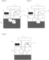
Figure 4 - is the schematic view of the sump, wherein the level of the liquid in the sump is higher than the level of the first suction port, related to another embodiment of the present invention. -
Figure 5 - is the schematic view of the sump, wherein the level of the liquid in the sump is lower than the level of the first suction port and higher than the level of the second suction port, related to another embodiment of the present invention. -
Figure 6 - is the view of the sump, wherein the level of the liquid in the sump drops to the level of the second suction port, related to another embodiment of the present invention. - The elements illustrated in the figures are numbered as follows:
- 1- Laundry dryer
- 2- Body
- 3- Drum
- 4- Condenser
- 5- Sump
- 6- Discharge line
- 7- Tank
- 8- Discharge pump
- 9- Fluid inlet
- 10- Supply pump
- 11- Delivery line
- 12- First suction port
- 13- Second suction port
- 14- Spraying member
- h: Height difference between the first suction port and the second suction port relative to the base of the sump
- The laundry dryer (1) comprises a body (2); a drum (3) which is disposed in the body (2) and wherein the laundry to be dried is loaded; a condenser (4) which is disposed in the body (2) and which dehumidifies the drying air; at least one sump (5) wherein the liquid formed in the condenser (4) is collected; a tank (7) which is connected to the sump (5) by means of a discharge line (6) and which receives the liquid in the sump (5); a discharge pump (8) which is disposed on the discharge line (6) and which is positioned in the sump (5); and at least one fluid inlet (9) which opens into the drum so as to enable the fluid to be supplied into the drum (3). The water formed in the condenser (4) is first collected in the sump (5). In the laundry dryers (1), there is generally a casing in the body (2) and at the bottom of the body (2), whereon components such as heat exchanger are placed. The sump (5) is preferred to be positioned on the casing. The condensate collected in the sump (5) is delivered to the tank (7) through the discharge line (6) by the discharge pump (8). The tank (7) can be preferably attached and detached by the user. The condensate directed to the tank (7) is discharged by the user. There is a fluid inlet (9) which opens into the drum (3) to deliver fluids such as steam or water droplets etc. into the drum (3).
- The laundry dryer (1) of the present invention comprises at least one supply pump (10) which is disposed in the sump (5) and at least one delivery line (11) one end of which is connected to the fluid inlet (9) and the other end to the supply pump (10) and which enables the liquid to be taken from the sump (5) to be delivered to the fluid inlet (9) by means of the supply pump (10). While the condensate in the sump (5) is being delivered to the tank (7) through the discharge line (6), the condensate in the sump (5) is delivered to the fluid inlet (9) through the delivery line (11). Thus, the need for using any valve to direct the water in the sump (5) to the tank (7) or the fluid inlet (9) is eliminated. In addition, since devices such as valves are not used, the strain on the control unit resulting from complex algorithms and therefore the occurrence of various technical problems are prevented.
- In an embodiment of the invention, on the discharge pump (8), there is at least one first suction port (12) which enables the liquid in the sump (5) to be taken into the discharge pump (8), and on the supply pump (10), there is at least one second suction port (13) which enables the liquid in the sump (5) to be supplied into the supply pump (10), and the discharge pump (8) is positioned in the sump (5) such that the second suction port (13) is lower than the first suction port (12). The discharge pump (8) delivers the liquid collected above the level of the first suction port (12) to the tank (7). When there is no liquid left at the first suction port (12) to be sucked into the discharge pump (8), in other words, when the liquid level in the sump (5) drops below the level of the first suction port (12), the discharge pump (8) cannot deliver liquid to the tank (7). The liquid as much as the height difference (h) between the first suction port (12) and the second suction port (13) relative to the base of the sump (5) is kept ready in the sump (5) to be supplied to the fluid inlet (9). The supply pump (10) is operated at the time interval predetermined by the manufacturer or when a wrinkle removal program wherein the wrinkles in the laundry are reduced is activated. Since there is always liquid in the second suction port (13), the technical problem of the lack of liquid in the sump (5) when the supply pump (10) is operated, and therefore of the failure to supply liquid to the fluid inlet (9) is prevented.
- In another embodiment of the present invention, the first suction port (12) and/or the second suction port (13) faces the base of the sump (5). The first suction port (12) is positioned at the base of the discharge pump (9) and the second suction port (13) is positioned at the base of the supply pump (10). Thus, by increasing the hydrostatic pressure of the liquid collected in the sump (5) on the first suction port (12) and/or the second suction port (13), supplying liquid into the discharge pump (8) and/or the supply pump (10) is facilitated.
- In another embodiment of the present invention, the supply pump (10) is disposed on the base of the sump (5). Thus, the liquid is prevented from always being present in the sump (5) and the liquid collected in the sump (5) is prevented from causing bad odor over time.
- In another embodiment of the present invention, on the fluid inlet (9), there is at least one spraying member (14) which enables the water carried by the delivery line (11) to be sprayed into the drum (3) in the form of droplets. Thus, during the drying cycle, the water droplets sprayed from the spraying member (14) into the drum (3) evaporate due to the internal temperature of the drum (3), increasing the wrinkle removal performance. In a preferred version of this embodiment, the spraying member (14) sprays extremely small amounts of water droplets and thus the water droplets sprayed from the spraying member (14) evaporate instantly. Therefore, the spraying member (14) is also used as a steam provider. Thus, the wrinkle performance is increased at an optimum level.
- In another embodiment of the present invention, the supply pump (10) is a centrifugal pump or a diaphragm pump. By using a centrifugal pump, the flow rate of the liquid supplied to the fluid inlet (9) is increased. The diaphragm pump is preferred because of its relatively smaller size and its ability to enable the second suction port (13) to be easily positioned in the region preferred by the manufacturer in the sump (5).
- In another embodiment of the present invention, the delivery line (11) is manufactured from a flexible material. Thus, the placement of the delivery line (11) between the supply pump (10) and the fluid inlet (9) is facilitated.
- By means of the present invention, a laundry dryer (1) is realized, wherein the wrinkles in the laundry are removed with a simple and cost-efficient embodiment by placing a supply pump (10) in the sump (5) where the condensate formed in the condenser (4) is collected in addition to the discharge pump (8). Moreover, by means of the present invention, by ensuring that the first suction port (12) and the second suction port (13) are positioned in the sump (5) at different heights relative to the base of the sump (5), the water to be supplied to the fluid inlet (9) is enabled to be always kept ready in the sump (5).
Claims (7)
- A laundry dryer (1) comprising a body (2); a drum (3) which is disposed in the body (2) and wherein the laundry to be dried is loaded; a condenser (4) which is disposed in the body (2) and which dehumidifies the drying air; at least one sump (5) wherein the liquid formed in the condenser (4) is collected; a tank (7) which is connected to the sump (5) by means of a discharge line (6) and which receives the liquid in the sump (5); a discharge pump (8) which is disposed on the discharge line (6) and which is positioned in the sump (5); and at least one fluid inlet (9) which opens into the drum so as to enable the fluid to be supplied into the drum (3), characterized by at least one supply pump (10) which is disposed in the sump (5) and at least one delivery line (11) one end of which is connected to the fluid inlet (9) and the other end to the supply pump (10) and which enables the liquid to be taken from the sump (5) to be delivered to the fluid inlet (9) by means of the supply pump (10).
- A laundry dryer (1) as in Claim 1, characterized by at least one first suction port (12) which is provided on the discharge pump (8) and which enables the liquid in the sump (5) to be taken into the discharge pump (8), at least one second suction port (13) which is provided on the supply pump (10) and which enables the liquid in the sump (5) to be supplied into the supply pump (10), and the discharge pump (8) which is positioned in the sump (5) such that the second suction port (13) is lower than the first suction port (12).
- A laundry dryer (1) as in Claim 2, characterized by the first suction port (12) and/or the second suction port (13) which faces the base of the sump (5).
- A laundry dryer (1) as in any one of the above claims, characterized by the supply pump (10) which is disposed on the base of the sump (5).
- A laundry dryer (1) as in any one of the above claims, characterized by at least one spraying member (14) which is provided on the fluid inlet (9) and which enables the water carried by the delivery line (11) to be sprayed into the drum (3) in the form of droplets.
- A laundry dryer (1) as in any one of the above claims, characterized by the supply pump (10) which is a centrifugal pump or a diaphragm pump.
- A laundry dryer (1) as in any one of the above claims, characterized by the delivery line (11) which is manufactured from a flexible material.
Applications Claiming Priority (1)
| Application Number | Priority Date | Filing Date | Title |
|---|---|---|---|
| TR202220285 | 2022-12-23 |
Publications (2)
| Publication Number | Publication Date |
|---|---|
| EP4389958A1 true EP4389958A1 (en) | 2024-06-26 |
| EP4389958B1 EP4389958B1 (en) | 2025-08-06 |
Family
ID=88647398
Family Applications (1)
| Application Number | Title | Priority Date | Filing Date |
|---|---|---|---|
| EP23207218.1A Active EP4389958B1 (en) | 2022-12-23 | 2023-10-31 | A laundry dryer |
Country Status (1)
| Country | Link |
|---|---|
| EP (1) | EP4389958B1 (en) |
Citations (5)
| Publication number | Priority date | Publication date | Assignee | Title |
|---|---|---|---|---|
| EP2520706A2 (en) * | 2011-05-03 | 2012-11-07 | Miele & Cie. KG | Laundry dryer |
| FR3006336A1 (en) * | 2013-06-03 | 2014-12-05 | Fagorbrandt Sas | METHOD FOR CONTROLLING THE OPERATION OF A LAUNDRY DRYING APPARATUS AND APPARATUS FOR DRYING THE LAUNDRY THEREFOR |
| US20160115643A1 (en) * | 2013-05-24 | 2016-04-28 | Electrolux Appliances Aktiebolag | Laundry Dryer and Method of Operating a Laundry Dryer |
| WO2020015914A1 (en) | 2018-07-19 | 2020-01-23 | Arcelik Anonim Sirketi | Steam sprayer |
| EP3933097A1 (en) * | 2020-06-29 | 2022-01-05 | Arçelik Anonim Sirketi | A laundry dryer |
-
2023
- 2023-10-31 EP EP23207218.1A patent/EP4389958B1/en active Active
Patent Citations (5)
| Publication number | Priority date | Publication date | Assignee | Title |
|---|---|---|---|---|
| EP2520706A2 (en) * | 2011-05-03 | 2012-11-07 | Miele & Cie. KG | Laundry dryer |
| US20160115643A1 (en) * | 2013-05-24 | 2016-04-28 | Electrolux Appliances Aktiebolag | Laundry Dryer and Method of Operating a Laundry Dryer |
| FR3006336A1 (en) * | 2013-06-03 | 2014-12-05 | Fagorbrandt Sas | METHOD FOR CONTROLLING THE OPERATION OF A LAUNDRY DRYING APPARATUS AND APPARATUS FOR DRYING THE LAUNDRY THEREFOR |
| WO2020015914A1 (en) | 2018-07-19 | 2020-01-23 | Arcelik Anonim Sirketi | Steam sprayer |
| EP3933097A1 (en) * | 2020-06-29 | 2022-01-05 | Arçelik Anonim Sirketi | A laundry dryer |
Also Published As
| Publication number | Publication date |
|---|---|
| EP4389958B1 (en) | 2025-08-06 |
Similar Documents
| Publication | Publication Date | Title |
|---|---|---|
| US11585032B2 (en) | Laundry treating appliance and method of operation | |
| CN103547728B (en) | There is the device for clothing processing of heat exchanger cleaning device | |
| KR101199396B1 (en) | drying device | |
| EP2826909B1 (en) | Method for operating a steam generation unit in a laundry dryer and method of operating a laundry dryer | |
| CN114127359A (en) | Clothes treating apparatus | |
| KR102527575B1 (en) | Dish Washer | |
| KR20120110497A (en) | Cleaning nozzle for a heat exchanger and heat exchanger cleaning apparatus using the same | |
| EP1887127B1 (en) | Laundry treating machine | |
| KR102595023B1 (en) | Dish washer | |
| EP3224402A1 (en) | A laundry dryer | |
| EP2019160B1 (en) | Washer-drier machine | |
| EP4389958B1 (en) | A laundry dryer | |
| EP3874085B1 (en) | A hybrid laundry dryer | |
| EP2821540B1 (en) | Laundry drying domestic appliance having a steam nozzle unit | |
| KR102493164B1 (en) | Dish Washer | |
| EP3933097B1 (en) | A laundry dryer | |
| EP3335613A1 (en) | Device for the condensation of steam in an air recirculation circuit of an industrial dishwasher or the like | |
| EP2610394B1 (en) | Laundry drying domestic appliance having a steam nozzle unit | |
| EP3855996B1 (en) | A heat pump dishwasher comprising an evaporator tray | |
| TR2022020285A2 (en) | A DRYER | |
| WO2020015914A1 (en) | Steam sprayer | |
| KR20120110499A (en) | Cleaning nozzle for a heat exchanger and heat exchanger cleaning apparatus using the same | |
| CN110081672B (en) | Dried tofu drying and cooling equipment | |
| JP5274900B2 (en) | Steam waste heat recovery system | |
| US20210307586A1 (en) | Dishwasher |
Legal Events
| Date | Code | Title | Description |
|---|---|---|---|
| PUAI | Public reference made under article 153(3) epc to a published international application that has entered the european phase |
Free format text: ORIGINAL CODE: 0009012 |
|
| STAA | Information on the status of an ep patent application or granted ep patent |
Free format text: STATUS: REQUEST FOR EXAMINATION WAS MADE |
|
| 17P | Request for examination filed |
Effective date: 20231101 |
|
| AK | Designated contracting states |
Kind code of ref document: A1 Designated state(s): AL AT BE BG CH CY CZ DE DK EE ES FI FR GB GR HR HU IE IS IT LI LT LU LV MC ME MK MT NL NO PL PT RO RS SE SI SK SM TR |
|
| GRAP | Despatch of communication of intention to grant a patent |
Free format text: ORIGINAL CODE: EPIDOSNIGR1 |
|
| STAA | Information on the status of an ep patent application or granted ep patent |
Free format text: STATUS: GRANT OF PATENT IS INTENDED |
|
| RIC1 | Information provided on ipc code assigned before grant |
Ipc: D06F 58/24 20060101ALN20250313BHEP Ipc: D06F 58/20 20060101AFI20250313BHEP |
|
| INTG | Intention to grant announced |
Effective date: 20250328 |
|
| GRAS | Grant fee paid |
Free format text: ORIGINAL CODE: EPIDOSNIGR3 |
|
| GRAA | (expected) grant |
Free format text: ORIGINAL CODE: 0009210 |
|
| STAA | Information on the status of an ep patent application or granted ep patent |
Free format text: STATUS: THE PATENT HAS BEEN GRANTED |
|
| AK | Designated contracting states |
Kind code of ref document: B1 Designated state(s): AL AT BE BG CH CY CZ DE DK EE ES FI FR GB GR HR HU IE IS IT LI LT LU LV MC ME MK MT NL NO PL PT RO RS SE SI SK SM TR |
|
| REG | Reference to a national code |
Ref country code: GB Ref legal event code: FG4D |
|
| REG | Reference to a national code |
Ref country code: CH Ref legal event code: EP |
|
| REG | Reference to a national code |
Ref country code: IE Ref legal event code: FG4D |
|
| REG | Reference to a national code |
Ref country code: DE Ref legal event code: R096 Ref document number: 602023005450 Country of ref document: DE |
|
| REG | Reference to a national code |
Ref country code: NL Ref legal event code: MP Effective date: 20250806 |
|
| PG25 | Lapsed in a contracting state [announced via postgrant information from national office to epo] |
Ref country code: IS Free format text: LAPSE BECAUSE OF FAILURE TO SUBMIT A TRANSLATION OF THE DESCRIPTION OR TO PAY THE FEE WITHIN THE PRESCRIBED TIME-LIMIT Effective date: 20251206 |
|
| PGFP | Annual fee paid to national office [announced via postgrant information from national office to epo] |
Ref country code: DE Payment date: 20251128 Year of fee payment: 3 |
|
| PG25 | Lapsed in a contracting state [announced via postgrant information from national office to epo] |
Ref country code: NO Free format text: LAPSE BECAUSE OF FAILURE TO SUBMIT A TRANSLATION OF THE DESCRIPTION OR TO PAY THE FEE WITHIN THE PRESCRIBED TIME-LIMIT Effective date: 20251106 |
|
| REG | Reference to a national code |
Ref country code: LT Ref legal event code: MG9D |
|
| PG25 | Lapsed in a contracting state [announced via postgrant information from national office to epo] |
Ref country code: PT Free format text: LAPSE BECAUSE OF FAILURE TO SUBMIT A TRANSLATION OF THE DESCRIPTION OR TO PAY THE FEE WITHIN THE PRESCRIBED TIME-LIMIT Effective date: 20251209 |
|
| PG25 | Lapsed in a contracting state [announced via postgrant information from national office to epo] |
Ref country code: FI Free format text: LAPSE BECAUSE OF FAILURE TO SUBMIT A TRANSLATION OF THE DESCRIPTION OR TO PAY THE FEE WITHIN THE PRESCRIBED TIME-LIMIT Effective date: 20250806 |
|
| PGFP | Annual fee paid to national office [announced via postgrant information from national office to epo] |
Ref country code: IT Payment date: 20251031 Year of fee payment: 3 |
|
| PG25 | Lapsed in a contracting state [announced via postgrant information from national office to epo] |
Ref country code: HR Free format text: LAPSE BECAUSE OF FAILURE TO SUBMIT A TRANSLATION OF THE DESCRIPTION OR TO PAY THE FEE WITHIN THE PRESCRIBED TIME-LIMIT Effective date: 20250806 Ref country code: NL Free format text: LAPSE BECAUSE OF FAILURE TO SUBMIT A TRANSLATION OF THE DESCRIPTION OR TO PAY THE FEE WITHIN THE PRESCRIBED TIME-LIMIT Effective date: 20250806 |
|
| PGFP | Annual fee paid to national office [announced via postgrant information from national office to epo] |
Ref country code: FR Payment date: 20251128 Year of fee payment: 3 |
|
| PG25 | Lapsed in a contracting state [announced via postgrant information from national office to epo] |
Ref country code: GR Free format text: LAPSE BECAUSE OF FAILURE TO SUBMIT A TRANSLATION OF THE DESCRIPTION OR TO PAY THE FEE WITHIN THE PRESCRIBED TIME-LIMIT Effective date: 20251107 |
|
| PGFP | Annual fee paid to national office [announced via postgrant information from national office to epo] |
Ref country code: TR Payment date: 20251104 Year of fee payment: 3 |
|
| PG25 | Lapsed in a contracting state [announced via postgrant information from national office to epo] |
Ref country code: SE Free format text: LAPSE BECAUSE OF FAILURE TO SUBMIT A TRANSLATION OF THE DESCRIPTION OR TO PAY THE FEE WITHIN THE PRESCRIBED TIME-LIMIT Effective date: 20250806 |
|
| PG25 | Lapsed in a contracting state [announced via postgrant information from national office to epo] |
Ref country code: LV Free format text: LAPSE BECAUSE OF FAILURE TO SUBMIT A TRANSLATION OF THE DESCRIPTION OR TO PAY THE FEE WITHIN THE PRESCRIBED TIME-LIMIT Effective date: 20250806 |
|
| PG25 | Lapsed in a contracting state [announced via postgrant information from national office to epo] |
Ref country code: BG Free format text: LAPSE BECAUSE OF FAILURE TO SUBMIT A TRANSLATION OF THE DESCRIPTION OR TO PAY THE FEE WITHIN THE PRESCRIBED TIME-LIMIT Effective date: 20250806 Ref country code: PL Free format text: LAPSE BECAUSE OF FAILURE TO SUBMIT A TRANSLATION OF THE DESCRIPTION OR TO PAY THE FEE WITHIN THE PRESCRIBED TIME-LIMIT Effective date: 20250806 |
|
| PG25 | Lapsed in a contracting state [announced via postgrant information from national office to epo] |
Ref country code: RS Free format text: LAPSE BECAUSE OF FAILURE TO SUBMIT A TRANSLATION OF THE DESCRIPTION OR TO PAY THE FEE WITHIN THE PRESCRIBED TIME-LIMIT Effective date: 20251106 |
|
| PG25 | Lapsed in a contracting state [announced via postgrant information from national office to epo] |
Ref country code: ES Free format text: LAPSE BECAUSE OF FAILURE TO SUBMIT A TRANSLATION OF THE DESCRIPTION OR TO PAY THE FEE WITHIN THE PRESCRIBED TIME-LIMIT Effective date: 20250806 |
|
| REG | Reference to a national code |
Ref country code: AT Ref legal event code: MK05 Ref document number: 1821940 Country of ref document: AT Kind code of ref document: T Effective date: 20250806 |
|
| PG25 | Lapsed in a contracting state [announced via postgrant information from national office to epo] |
Ref country code: RO Free format text: LAPSE BECAUSE OF FAILURE TO SUBMIT A TRANSLATION OF THE DESCRIPTION OR TO PAY THE FEE WITHIN THE PRESCRIBED TIME-LIMIT Effective date: 20250806 |
|
| PG25 | Lapsed in a contracting state [announced via postgrant information from national office to epo] |
Ref country code: SM Free format text: LAPSE BECAUSE OF FAILURE TO SUBMIT A TRANSLATION OF THE DESCRIPTION OR TO PAY THE FEE WITHIN THE PRESCRIBED TIME-LIMIT Effective date: 20250806 |
|
| PG25 | Lapsed in a contracting state [announced via postgrant information from national office to epo] |
Ref country code: DK Free format text: LAPSE BECAUSE OF FAILURE TO SUBMIT A TRANSLATION OF THE DESCRIPTION OR TO PAY THE FEE WITHIN THE PRESCRIBED TIME-LIMIT Effective date: 20250806 |
|
| PG25 | Lapsed in a contracting state [announced via postgrant information from national office to epo] |
Ref country code: AT Free format text: LAPSE BECAUSE OF FAILURE TO SUBMIT A TRANSLATION OF THE DESCRIPTION OR TO PAY THE FEE WITHIN THE PRESCRIBED TIME-LIMIT Effective date: 20250806 |
|
| PG25 | Lapsed in a contracting state [announced via postgrant information from national office to epo] |
Ref country code: CZ Free format text: LAPSE BECAUSE OF FAILURE TO SUBMIT A TRANSLATION OF THE DESCRIPTION OR TO PAY THE FEE WITHIN THE PRESCRIBED TIME-LIMIT Effective date: 20250806 |
|
| PG25 | Lapsed in a contracting state [announced via postgrant information from national office to epo] |
Ref country code: SK Free format text: LAPSE BECAUSE OF FAILURE TO SUBMIT A TRANSLATION OF THE DESCRIPTION OR TO PAY THE FEE WITHIN THE PRESCRIBED TIME-LIMIT Effective date: 20250806 Ref country code: EE Free format text: LAPSE BECAUSE OF FAILURE TO SUBMIT A TRANSLATION OF THE DESCRIPTION OR TO PAY THE FEE WITHIN THE PRESCRIBED TIME-LIMIT Effective date: 20250806 |
|
| REG | Reference to a national code |
Ref country code: DE Ref legal event code: R097 Ref document number: 602023005450 Country of ref document: DE |
|
| PLBE | No opposition filed within time limit |
Free format text: ORIGINAL CODE: 0009261 |
|
| STAA | Information on the status of an ep patent application or granted ep patent |
Free format text: STATUS: NO OPPOSITION FILED WITHIN TIME LIMIT |
|
| PG25 | Lapsed in a contracting state [announced via postgrant information from national office to epo] |
Ref country code: LU Free format text: LAPSE BECAUSE OF NON-PAYMENT OF DUE FEES Effective date: 20251031 |
|
| REG | Reference to a national code |
Ref country code: CH Ref legal event code: L10 Free format text: ST27 STATUS EVENT CODE: U-0-0-L10-L00 (AS PROVIDED BY THE NATIONAL OFFICE) Effective date: 20260617 |
|
| REG | Reference to a national code |
Ref country code: BE Ref legal event code: MM Effective date: 20251031 |
|
| PG25 | Lapsed in a contracting state [announced via postgrant information from national office to epo] |
Ref country code: MC Free format text: LAPSE BECAUSE OF FAILURE TO SUBMIT A TRANSLATION OF THE DESCRIPTION OR TO PAY THE FEE WITHIN THE PRESCRIBED TIME-LIMIT Effective date: 20250806 Ref country code: LT Free format text: LAPSE BECAUSE OF FAILURE TO SUBMIT A TRANSLATION OF THE DESCRIPTION OR TO PAY THE FEE WITHIN THE PRESCRIBED TIME-LIMIT Effective date: 20250806 |
|
| 26N | No opposition filed |
Effective date: 20260507 |
|
| PG25 | Lapsed in a contracting state [announced via postgrant information from national office to epo] |
Ref country code: BE Free format text: LAPSE BECAUSE OF NON-PAYMENT OF DUE FEES Effective date: 20251031 |