EP4389933A1 - Distribution arrangement - Google Patents
Distribution arrangement Download PDFInfo
- Publication number
- EP4389933A1 EP4389933A1 EP22215789.3A EP22215789A EP4389933A1 EP 4389933 A1 EP4389933 A1 EP 4389933A1 EP 22215789 A EP22215789 A EP 22215789A EP 4389933 A1 EP4389933 A1 EP 4389933A1
- Authority
- EP
- European Patent Office
- Prior art keywords
- primary
- base portion
- slab
- distribution arrangement
- cavity
- Prior art date
- Legal status (The legal status is an assumption and is not a legal conclusion. Google has not performed a legal analysis and makes no representation as to the accuracy of the status listed.)
- Granted
Links
Images







Classifications
-
- F—MECHANICAL ENGINEERING; LIGHTING; HEATING; WEAPONS; BLASTING
- F28—HEAT EXCHANGE IN GENERAL
- F28D—HEAT-EXCHANGE APPARATUS, NOT PROVIDED FOR IN ANOTHER SUBCLASS, IN WHICH THE HEAT-EXCHANGE MEDIA DO NOT COME INTO DIRECT CONTACT
- F28D9/00—Heat-exchange apparatus having stationary plate-like or laminated conduit assemblies for both heat-exchange media, the media being in contact with different sides of a conduit wall
- F28D9/0031—Heat-exchange apparatus having stationary plate-like or laminated conduit assemblies for both heat-exchange media, the media being in contact with different sides of a conduit wall the conduits for one heat-exchange medium being formed by paired plates touching each other
- F28D9/0043—Heat-exchange apparatus having stationary plate-like or laminated conduit assemblies for both heat-exchange media, the media being in contact with different sides of a conduit wall the conduits for one heat-exchange medium being formed by paired plates touching each other the plates having openings therein for circulation of at least one heat-exchange medium from one conduit to another
- F28D9/005—Heat-exchange apparatus having stationary plate-like or laminated conduit assemblies for both heat-exchange media, the media being in contact with different sides of a conduit wall the conduits for one heat-exchange medium being formed by paired plates touching each other the plates having openings therein for circulation of at least one heat-exchange medium from one conduit to another the plates having openings therein for both heat-exchange media
-
- C—CHEMISTRY; METALLURGY
- C25—ELECTROLYTIC OR ELECTROPHORETIC PROCESSES; APPARATUS THEREFOR
- C25B—ELECTROLYTIC OR ELECTROPHORETIC PROCESSES FOR THE PRODUCTION OF COMPOUNDS OR NON-METALS; APPARATUS THEREFOR
- C25B1/00—Electrolytic production of inorganic compounds or non-metals
- C25B1/01—Products
- C25B1/02—Hydrogen or oxygen
- C25B1/04—Hydrogen or oxygen by electrolysis of water
-
- C—CHEMISTRY; METALLURGY
- C25—ELECTROLYTIC OR ELECTROPHORETIC PROCESSES; APPARATUS THEREFOR
- C25B—ELECTROLYTIC OR ELECTROPHORETIC PROCESSES FOR THE PRODUCTION OF COMPOUNDS OR NON-METALS; APPARATUS THEREFOR
- C25B11/00—Electrodes; Manufacture thereof not otherwise provided for
- C25B11/02—Electrodes; Manufacture thereof not otherwise provided for characterised by shape or form
-
- C—CHEMISTRY; METALLURGY
- C25—ELECTROLYTIC OR ELECTROPHORETIC PROCESSES; APPARATUS THEREFOR
- C25B—ELECTROLYTIC OR ELECTROPHORETIC PROCESSES FOR THE PRODUCTION OF COMPOUNDS OR NON-METALS; APPARATUS THEREFOR
- C25B15/00—Operating or servicing cells
- C25B15/08—Supplying or removing reactants or electrolytes; Regeneration of electrolytes
-
- C—CHEMISTRY; METALLURGY
- C25—ELECTROLYTIC OR ELECTROPHORETIC PROCESSES; APPARATUS THEREFOR
- C25B—ELECTROLYTIC OR ELECTROPHORETIC PROCESSES FOR THE PRODUCTION OF COMPOUNDS OR NON-METALS; APPARATUS THEREFOR
- C25B9/00—Cells or assemblies of cells; Constructional parts of cells; Assemblies of constructional parts, e.g. electrode-diaphragm assemblies; Process-related cell features
- C25B9/60—Constructional parts of cells
- C25B9/67—Heating or cooling means
-
- C—CHEMISTRY; METALLURGY
- C25—ELECTROLYTIC OR ELECTROPHORETIC PROCESSES; APPARATUS THEREFOR
- C25B—ELECTROLYTIC OR ELECTROPHORETIC PROCESSES FOR THE PRODUCTION OF COMPOUNDS OR NON-METALS; APPARATUS THEREFOR
- C25B9/00—Cells or assemblies of cells; Constructional parts of cells; Assemblies of constructional parts, e.g. electrode-diaphragm assemblies; Process-related cell features
- C25B9/70—Assemblies comprising two or more cells
-
- C—CHEMISTRY; METALLURGY
- C25—ELECTROLYTIC OR ELECTROPHORETIC PROCESSES; APPARATUS THEREFOR
- C25B—ELECTROLYTIC OR ELECTROPHORETIC PROCESSES FOR THE PRODUCTION OF COMPOUNDS OR NON-METALS; APPARATUS THEREFOR
- C25B9/00—Cells or assemblies of cells; Constructional parts of cells; Assemblies of constructional parts, e.g. electrode-diaphragm assemblies; Process-related cell features
- C25B9/70—Assemblies comprising two or more cells
- C25B9/73—Assemblies comprising two or more cells of the filter-press type
-
- F—MECHANICAL ENGINEERING; LIGHTING; HEATING; WEAPONS; BLASTING
- F28—HEAT EXCHANGE IN GENERAL
- F28F—DETAILS OF HEAT-EXCHANGE AND HEAT-TRANSFER APPARATUS, OF GENERAL APPLICATION
- F28F3/00—Plate-like or laminated elements; Assemblies of plate-like or laminated elements
- F28F3/02—Elements or assemblies thereof with means for increasing heat-transfer area, e.g. with fins, with recesses, with corrugations
- F28F3/04—Elements or assemblies thereof with means for increasing heat-transfer area, e.g. with fins, with recesses, with corrugations the means being integral with the element
- F28F3/042—Elements or assemblies thereof with means for increasing heat-transfer area, e.g. with fins, with recesses, with corrugations the means being integral with the element in the form of local deformations of the element
- F28F3/046—Elements or assemblies thereof with means for increasing heat-transfer area, e.g. with fins, with recesses, with corrugations the means being integral with the element in the form of local deformations of the element the deformations being linear, e.g. corrugations
-
- F—MECHANICAL ENGINEERING; LIGHTING; HEATING; WEAPONS; BLASTING
- F28—HEAT EXCHANGE IN GENERAL
- F28F—DETAILS OF HEAT-EXCHANGE AND HEAT-TRANSFER APPARATUS, OF GENERAL APPLICATION
- F28F3/00—Plate-like or laminated elements; Assemblies of plate-like or laminated elements
- F28F3/08—Elements constructed for building-up into stacks, e.g. capable of being taken apart for cleaning
- F28F3/083—Elements constructed for building-up into stacks, e.g. capable of being taken apart for cleaning capable of being taken apart
-
- F—MECHANICAL ENGINEERING; LIGHTING; HEATING; WEAPONS; BLASTING
- F28—HEAT EXCHANGE IN GENERAL
- F28F—DETAILS OF HEAT-EXCHANGE AND HEAT-TRANSFER APPARATUS, OF GENERAL APPLICATION
- F28F3/00—Plate-like or laminated elements; Assemblies of plate-like or laminated elements
- F28F3/08—Elements constructed for building-up into stacks, e.g. capable of being taken apart for cleaning
- F28F3/10—Arrangements for sealing the margins
-
- F—MECHANICAL ENGINEERING; LIGHTING; HEATING; WEAPONS; BLASTING
- F28—HEAT EXCHANGE IN GENERAL
- F28F—DETAILS OF HEAT-EXCHANGE AND HEAT-TRANSFER APPARATUS, OF GENERAL APPLICATION
- F28F9/00—Casings; Header boxes; Auxiliary supports for elements; Auxiliary members within casings
- F28F9/02—Header boxes; End plates
- F28F9/026—Header boxes; End plates with static flow control means, e.g. with means for uniformly distributing heat exchange media into conduits
-
- C—CHEMISTRY; METALLURGY
- C25—ELECTROLYTIC OR ELECTROPHORETIC PROCESSES; APPARATUS THEREFOR
- C25B—ELECTROLYTIC OR ELECTROPHORETIC PROCESSES FOR THE PRODUCTION OF COMPOUNDS OR NON-METALS; APPARATUS THEREFOR
- C25B1/00—Electrolytic production of inorganic compounds or non-metals
- C25B1/01—Products
- C25B1/34—Simultaneous production of alkali metal hydroxides and chlorine, oxyacids or salts of chlorine, e.g. by chlor-alkali electrolysis
-
- F—MECHANICAL ENGINEERING; LIGHTING; HEATING; WEAPONS; BLASTING
- F28—HEAT EXCHANGE IN GENERAL
- F28D—HEAT-EXCHANGE APPARATUS, NOT PROVIDED FOR IN ANOTHER SUBCLASS, IN WHICH THE HEAT-EXCHANGE MEDIA DO NOT COME INTO DIRECT CONTACT
- F28D21/00—Heat-exchange apparatus not covered by any of the groups F28D1/00 - F28D20/00
- F28D2021/0019—Other heat exchangers for particular applications; Heat exchange systems not otherwise provided for
- F28D2021/0022—Other heat exchangers for particular applications; Heat exchange systems not otherwise provided for for chemical reactors
-
- F—MECHANICAL ENGINEERING; LIGHTING; HEATING; WEAPONS; BLASTING
- F28—HEAT EXCHANGE IN GENERAL
- F28D—HEAT-EXCHANGE APPARATUS, NOT PROVIDED FOR IN ANOTHER SUBCLASS, IN WHICH THE HEAT-EXCHANGE MEDIA DO NOT COME INTO DIRECT CONTACT
- F28D21/00—Heat-exchange apparatus not covered by any of the groups F28D1/00 - F28D20/00
- F28D2021/0019—Other heat exchangers for particular applications; Heat exchange systems not otherwise provided for
- F28D2021/0043—Other heat exchangers for particular applications; Heat exchange systems not otherwise provided for for fuel cells
-
- F—MECHANICAL ENGINEERING; LIGHTING; HEATING; WEAPONS; BLASTING
- F28—HEAT EXCHANGE IN GENERAL
- F28F—DETAILS OF HEAT-EXCHANGE AND HEAT-TRANSFER APPARATUS, OF GENERAL APPLICATION
- F28F2275/00—Fastening; Joining
- F28F2275/08—Fastening; Joining by clamping or clipping
- F28F2275/085—Fastening; Joining by clamping or clipping with snap connection
Definitions
- the invention relates to a distribution arrangement configured to be positioned between two corrugated heat transfer plates.
- the heat transfer plates and the distribution arrangement may be comprised in a device used for a heat generating process, such as electrolysis.
- Electrolysis is a well known process of using electricity to chemically decompose an electrolyte.
- electrolysis can be used to split water confined in an electrolyte into hydrogen and oxygen.
- heat may be generated, which heat may have to be diverted for maintained electrolysis efficiency.
- EP 4012070 discloses a heat exchanger comprising a stack of heat transfer plates.
- the heat exchanger is adapted for connection to an electrolyzing device such that fluids circulating in the electrolyzing device are made to pass the heat exchanger for regulation of their temperatures.
- the temperature of the fluids gradually increases inside the electrolyzing device.
- the heat exchanger receives fluids of relatively high temperature from the electrolyzing device and delivers fluids of relatively low temperature to the electrolyzing device, which means that there will be a temperature difference across the electrolyzing device. This may result in an uneven and non-optimal electrolysis process inside the electrolyzing device.
- the heat exchanger in EP 4012070 is a so called plate-and-shell heat exchanger.
- a plate heat exchanger typically comprises a number of corrugated heat transfer plates arranged aligned in a stack or pack. Sealings between the heat transfer plates define parallel flow channels between the heat transfer plates, one flow channel between each pair of adjacent heat transfer plates. Two fluids of initially different temperatures can be fed alternately through every second flow channel for transferring heat from one fluid to the other.
- An object of the present invention is to provide a distribution arrangement for positioning between two corrugated heat transfer plates so as to enable realization of a reliable and mechanically uncomplicated device comprising said heat transfer plates as part of a stack of corrugated heat transfer plates forming alternately arranged first and second plate interspaces, which device may be used for a heat generating process, such as electrolysis, and which device may allow a more uniform and effective cooling of a fluid, such as an electrolyte, and the products formed therefrom, so as to enable a maintained high process efficiency.
- the basic concept of the invention is to offer a distribution arrangement that may be arranged in the first interspaces dedicated for cooling, such that a heat generating process can be effectively maintained in the second interspaces, which distribution arrangement allows use of the first interspaces to feed fluid into, and out of, the second interspaces.
- the basic concept of the invention is to offer a distribution arrangement that enables a device for performing a heat generating process, such as electrolysis, which device, at the same time, may function as a traditional heat exchanger so as to provide cooling "integrated" in the heat generating process.
- the distribution arrangement may be used in a device for production of hydrogen.
- the distribution arrangement according to the invention is not arranged for use on its own, but as a component of a device as described above, the advantages of different features and embodiments of the distribution arrangement appears first when the distribution arrangement is installed in the device.
- the distribution arrangement may be used in a device of the above described type to feed fluid, here a second fluid, into and out of a second interspace via a first interspace.
- the distribution arrangement as used for feeding the second fluid into the second interspace is described in the rest of this "Summary”.
- the distribution arrangement is arranged for flow diversion in an advantageous way, as will be further describe below.
- the distribution arrangement as used for feeding the second fluid out of the second interspace is instead arranged for flow collection in a corresponding advantageous way, which will be further discussed in the "Detailed Description".
- a distribution arrangement is for positioning between two corrugated heat transfer plates which may be of the same or different types. It comprises a base portion which includes a slab having opposing front and back surfaces arranged to face a respective one of the heat transfer plates. An intermediate extension plane of the slab extends between the front and back surfaces of the slab. A front surface and a back surface of the base portion comprises at least a part of the front surface and the back surface, respectively, of the slab.
- the base portion comprises a through secondary hole which extends through the front and back surfaces of the base portion so as to form a direct secondary flow path through the base portion.
- the base portion also comprises a non-through first secondary cavity which extends through the front surface of the base portion.
- the base portion comprises at least one first secondary channel which extends inside the slab. Said at least one first secondary channel connects the secondary hole and the first secondary cavity to form a first transferred secondary flow path through the base portion.
- An annular secondary sub-surface of the front surface of the base portion encloses the secondary hole.
- annular and ring is not necessarily circular but may be any “closed” shape, such as oval, polygonal or any combination thereof.
- the intermediate extension plane of the slab may extend essentially parallel to the heat transfer plates.
- the intermediate extension plane of the slab may extend essentially parallel to the front and back surfaces of the slab.
- the intermediate extension plane may, or may not, extend halfway between the front and back surfaces of the slab.
- Said at least one first secondary channel which extends inside the slab may, or may not, extend essentially parallel to the intermediate extension plane of the slab.
- the first secondary cavity is non-through, it will extend only partly through the base portion, i.e. not through the back surface of the base portion.
- the distribution arrangement can be made of one ore more materials.
- the base portion of the distribution arrangement, and particularly the front and back surfaces of the base portion may be made of one or more insulating materials.
- the base portion may prevent short circuiting within a device for performing a heat generating process, such as electrolysis, which short circuiting could cause malfunctioning of the device.
- the distribution arrangement may further comprise a secondary hole gasket.
- the secondary hole gasket may enclose the secondary hole and seal against the secondary sub-surface of the front surface of the base portion.
- the secondary hole gasket may enable a tight seal between the secondary sub-surface and another surface, which surface may be comprised in another distribution arrangement according to the invention.
- the distribution arrangement may comprise a first secondary cavity gasket.
- the first secondary cavity gasket may enclose the first secondary cavity and seal against the front surface of the base portion.
- the first secondary cavity gasket may enable a tight seal between the front surface of the base portion and another surface, which surface may be comprised in a heat transfer plate.
- the distribution arrangement may be so designed that the secondary sub-surface is elevated in relation to the rest of the front surface of the base portion. Thereby, the base portion will have an increased thickness around the secondary hole.
- Such a design may enable for the distribution arrangement to project through a heat transfer plate to prevent short circuiting within a device for performing a heat generating process, such as electrolysis.
- the base portion may further comprise a through primary hole.
- the primary hole may extend through the front and back surfaces of the base portion so as to form a direct primary flow path through the base portion.
- the base portion may further comprise a non-through first primary cavity which extends through the back surface of the base portion, and at least one first primary channel extending inside the slab. Said at least one first primary channel may connect the primary hole and the first primary cavity to form a first transferred primary flow path through the base portion.
- An annular primary sub-surface of the front surface of the base portion may enclose the primary hole.
- Said at least one first primary channel which extends inside the slab may, or may not, extend essentially parallel to the intermediate extension plane of the slab.
- the first primary cavity is non-through, it will extend only partly through the base portion, i.e. not through the front surface of the base portion.
- the distribution arrangement may divide a first primary sub flow from a second primary fluid flow.
- the distribution arrangement may it may convey the first primary sub flow of the second fluid into an adjacent second interspace via the first interspace, as will be further described below.
- the distribution arrangement may further comprise a primary hole gasket.
- the primary hole gasket may enclose the primary hole and seal against the primary sub-surface of the front surface of the base portion.
- the primary hole gasket may enable a tight seal between the primary sub-surface and another surface, which surface may be comprised in another distribution arrangement according to the invention.
- the distribution arrangement may comprise a first primary cavity gasket.
- the first primary cavity gasket may enclose the first primary cavity and seal against the back surface of the base portion.
- the first primary cavity gasket may enable a tight seal between the back surface of the base portion and another surface, which surface may be comprised in a heat transfer plate.
- the distribution arrangement may be so designed that the primary sub-surface is elevated in relation to the rest of the front surface of the base portion. Thereby, the base portion will have an increased thickness around the primary hole.
- the distribution arrangement may be such that the first secondary cavity is aligned with the first primary cavity. Then, a normal axis extending perpendicular to the intermediate extension plane of the slab may extend through both the first secondary cavity and the first primary cavity. Such a configuration may be advantageous in that it enables for said at least one first secondary channel and said at least one first primary channel to cross each other.
- the distribution arrangement may be such that the first secondary cavity is displaced from the first primary cavity. Then, a normal axis extending perpendicular to the intermediate extension plane of the slab may not extend through both the first secondary cavity and the first primary cavity.
- Such a configuration may be advantageous in that it enables for said at least one first secondary channel, as well as for said at least one first primary channel, to extend at any level between the front and back surfaces of the slab.
- the distribution arrangement may be so designed that said at least one first secondary channel extends between the front surface of the slab and the intermediate extension plane of the slab. Further, said at least one first primary channel may extend between the back surface of the slab and the intermediate extension plane of the slab. Such a configuration may be advantageous in that it enables for said at least one first secondary channel and said at least one first primary channel to cross each other.
- the base portion of the distribution arrangement may comprise a non-through second secondary cavity which extends through the front surface of the base portion, and at least one second secondary channel extending inside the slab. Said at least one second secondary channel may connect the secondary hole and the second secondary cavity to form a second transferred secondary flow path through the base portion. Additionally/alternatively, the base portion may comprise a non-through second primary cavity which extends through the back surface of the base portion, and at least one second primary channel extending inside the slab. Said at least one second primary channel may connect the primary hole and the second primary cavity to form a second transferred primary flow path through the base portion.
- Said at least one second secondary channel and/or said at least one second primary channel which extend inside the slab may, or may not, extend essentially parallel to the intermediate extension plane of the slab.
- the second secondary cavity is non-through, it will extend only partly through the base portion, i.e. not through the back surface of the base portion.
- the second primary cavity is non-through, it will extend only partly through the base portion, i.e. not through the front surface of the base portion.
- the distribution arrangement may divide a second secondary sub flow from the second secondary fluid flow.
- the distribution arrangement may be arranged in a first interspace of a device as described above, it may it may convey the second secondary sub flow of the second fluid into an adjacent second interspace via the first interspace.
- the first and second secondary sub flows may be conveyed into the second interspace at different positions which may improve the distribution of the second fluid in the second interspace.
- the distribution arrangement may divide a second primary sub flow from the second primary fluid flow.
- the distribution arrangement may be arranged in a first interspace of a device as described above, it may it may convey the second primary sub flow of the second fluid into an adjacent second interspace via the first interspace.
- the first and second primary sub flows may be conveyed into the second interspace at different positions which may improve the distribution of the second fluid in the second interspace.
- the distribution arrangement may be so designed that the first secondary cavity and the second secondary cavity are aligned with the second primary cavity and the first primary cavity, respectively.
- Such a configuration may be advantageous in that it enables for said at least one first secondary channel and said at least one second primary channel to cross each other, and for said at least one second secondary channel and said at least one first primary channel to cross each other.
- distribution arrangement may be so designed that the first secondary cavity and the second secondary cavity are displaced from the second primary cavity and the first primary cavity.
- Such a configuration may be advantageous in that it enables for said at least one first secondary channel, said at least one second secondary channel, said at least one first primary channel and said at least one second primary channel to extend at any level between the front and back surfaces of the slab.
- the distribution arrangement may be such that said at least one first secondary channel and said at least one second secondary channel extend between the front surface of the slab and the intermediate extension plane of the slab. Further, said at least one first primary channel and said at least one second primary channel may extend between the back surface of the slab and the intermediate extension plane of the slab. Such a configuration may be advantageous in that it enables for said at least one first secondary channel and said at least one second primary channel to cross each other, and for said at least one second secondary channel and said at least one first primary channel to cross each other.
- the distribution arrangement may be so designed that the slab comprises an inner wall enclosing, i.e. defining, the secondary hole.
- the inner wall may comprise first and second halves which extend on opposite sides of a hole center plane dividing the secondary hole in half, which hole center plane extends perpendicular to the intermediate extension plane of the slab.
- the first half of the inner wall of the slab may be arranged further away from the first secondary cavity than the second half of the inner wall of the slab.
- Said at least one first secondary channel may extend from an opening in the first half of the inner wall of the slab.
- Such a design may be advantageous when the distribution arrangement is arranged to be used with such an orientation that the first half of the inner wall is arranged above the second halv of the inner wall. Then, such a design may facilitate separation of a gas phase and a liquid phase of the second fluid in the secondary hole, as will be further described below.
- the primary hole of the distribution arrangement may have a similar construction.
- the slab of the distribution arrangement may be provided with a bar engagement recess.
- the bar engagement recess may be arranged for engagement with a bar of a device as described above, which bar is arranged to support the heat transfer plates of the device.
- the bar engagement recess may be used to secure the distribution arrangement, and any heat transfer plate engaging therewith, in the device.
- the bar engagement recess may be formed as a hole, cavity or hollow through the slab, defined by an annular inner wall of the slab.
- the bar engagement recess may extend from an outer edge of the slab, for example from a center portion of the outer edge.
- the bar engagement recess, which may be insulating, and the first secondary cavity may be arranged on opposite sides of the secondary hole.
- the recess may have any suitable shape.
- the distribution arrangement may further comprise snap fitting means projecting from the front surface of the slab around said annular secondary sub-surface, and possibly also around said annular primary sub-surface, of the front surface of the base portion.
- Said snap fitting means may be arranged to engage with locking means of one of said heat transfer plates to attach the distribution arrangement to said one of the heat transfer plates.
- Such snap fitting means may enable a simple and stable assembly of a device comprising the distribution arrangement and said heat transfer plates.
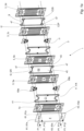
- Fig. 1a illustrates a part of a device 1 used for producing hydrogen through electrolysis, here alkaline water electrolysis.
- the device 1 comprises a stack 3 (only partly illustrated) of similar heat transfer plates 5 which each has a front side 7 and an opposing back side 9.
- the heat transfer plates 5 are flipped in relation to each other, i.e. arranged front side 7 to front side 7 and back side 9 to back side 9 with every second one of the heat transfer plates 5 turned upside down with respect to the rest of the heat transfer plates 5.
- every second one of the heat transfer plates 5 is rotated 180 degrees around a respective heat transfer plate longitudinal center axis L, and then rotated 180 degrees around a respective heat transfer plate normal axis N ( Fig. 2 ), with respect to the rest of the heat transfer plates 5.
- One of the heat transfer plates 5 is separately illustrated in Fig. 2 and described in further detail below. It has a first end portion 11, a center portion 13 and a second end portion 15 arranged in succession along the longitudinal center axis L of the heat transfer plate 5, which longitudinal center axis L extends perpendicular to a transverse center axis T of the heat transfer plate 5.
- the first end portion 11 comprises a first porthole 17, a third porthole 19, a fifth porthole 21, a seventh porthole 23 and a first transfer hole 25, while the second end portion 15 comprises a second porthole 27, a fourth porthole 29, a sixth porthole 31, an eighth porthole 33 and a second transfer hole 35.
- the heat transfer plate 5 is pressed with corrugation patterns of ridges and valleys in relation to a respective central extension plane of the heat transfer plate 5, which central extension plane is parallel to the figure plane of Fig. 2 .
- the corrugation patterns within different areas of the heat transfer plate 5 are different.
- the center portion 13 is pressed with a corrugation pattern of so-called herringbone type.
- an edge portion 37 of the heat transfer plate 5 is pressed with alternately arranged ridges and valleys extending from an outer edge 39 of the heat transfer plate 5.
- the stack 3 of heat transfer plates 5 is arranged between two frame plates F, of which only one is illustrated.
- the heat transfer plates 5 within the stack 3 are arranged in pairs, wherein heat transfer plates 5b and 5c form one of these pairs, while heat transfer plate 5d forms one of the heat transfer plates of another adjacent one of these pairs.
- the heat transfer plates of each pair form between them a first interspace 11.
- a second interspace I2 is formed between each two adjacent pairs of heat transfer plates 5.
- An outer heat transfer plate 5x which is similar to the heat transfer plates 5 except for that it lacks the first and second transfer holes 25 and 35, is arranged between the stack 3 and the frame plate F visible in Fig.
- An annular field gasket part 41 of rubber is arranged within each of the first interspaces I1 to define a first flow channel C1 therein.
- An annular field sealing part 43 is arranged within each of the second interspaces I2 to define a second flow channel C2 therein.
- a separation means, which closes a field sealing area enclosed by the field sealing part 43, comprises a hydroxide ion permeable membrane 45.
- the membrane 45 extends within the field sealing part 43 and essentially parallel to the heat transfer plates 5 to split the corresponding second flow channel C2 in a second primary sub channel C2P and a second secondary sub channel C2S, which sub channels are parallel and extend on opposite sides of the membrane 45.
- the field sealing part 43 and the separation means comprising the membrane 45 are parts of a sealing arrangement S of rubber (except for the membrane) which also comprises four annular ring sealing parts 47 formed integrally with the field sealing part 43 and an insulating rubber sheet (not illustrated herein).
- the rubber sheet extends on an outside of the field sealing part 43 and the ring sealing parts 47 and is arranged to prevent contact between the heat transfer plates arranged on the opposite sides of the rubber sheet.
- the field gasket part 41 encloses a field gasket area A1 having a transverse center axis T1 and a longitudinal center axis L1.
- the field gasket part 41 comprises first and second long side portions Is1 and Is2, which extend essentially parallel to the longitudinal center axis L1 of the field gasket area A1, and first and second short side portions ss1 and ss2.
- the first short side portion ss1 connects the long side portions Is1 and Is2 at a first end E1 of the field gasket part 41
- the second short side portion ss2 connects the long side portions Is1 and Is2 at a second end E2 of the field gasket part 41.
- the first and second short side portions ss1 and ss2 are bulging towards each other so as to form a first recess R1 on an outside of the first short side portion ss1 and a second recess R2 on an outside of the second short side portion ss2.
- the upper distribution arrangement 69a is partly arranged within the recess R1 of the field gasket part 41 while the lower distribution arrangement 69b is partly arranged within the recess R2 of the field gasket part 41.
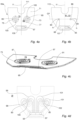
- the upper distribution arrangement 69a is separately illustrated in Figs. 4a-4d . It comprises a base portion 71 which is made of an insulating material such as a polymer.
- the base portion 71 consists of a slab, plate or disc 73 and two similar projections in the shape of thick-walled cylinders 75 and 77.
- the slab 73 has opposing front and back surfaces 79 and 81 of which the front surface 79 is visible in Figs. 4a and 4c and the back surface 81 is visible in Fig. 4b .
- Two holes h extend through the slab 73 on opposite sides of a longitudinal center axis I1 of the upper distribution arrangement 69a.
- the cylinders 75 and 77 project from the front surface 79 of the slab 73 and enclose a respective one of the holes h through the slab 73 to define a primary hole 83 and a secondary hole 85, respectively, through the base portion 71.
- the slab 73 comprises two inner walls 84 enclosing a respective one of the primary and secondary holes 83 and 85.
- Each of these inner walls 84 comprises a first half 86 and a second half 88 which extend on opposite sides of a hole center plane CP dividing the primary and secondary holes 83 and 85 in half.
- a free end surface of the cylinder 75 forms an elevated annular primary sub-surface 87 of a front surface 89 of the base portion 71.
- a free end surface of the cylinder 77 forms an elevated annular secondary sub-surface 91 of the front surface 89 of the base portion 71.
- the front surface 89 of the base portion 71 comprises this primary sub-surface 87 and this secondary sub-surface 91 and the portion of the front surface 79 of the slab 73 extending outside the cylinders 75 and 77.
- a back surface 93 of the base portion 71 comprises the back surface 81 of the slab 73.
- the base portion 71 comprises a non-through first primary cavity 95 extending through the back surface 93, and a non-through first secondary cavity 97 extending through the front surface 89, of the base portion 71.
- the first primary cavity 95 and the first secondary cavity 97 are displaced from each other, i.e. they are arranged on opposite sides of the longitudinal center axis I1 of the upper distribution arrangement 69a.
- Fig. 4d illustrates a cross section through the upper distribution arrangement 69a at an intermediate extension plane IP of the slab 73, which plane coincides with the figure plane of Fig. 4d and extends halfway between the front and back surfaces 79 and 81 of the slab 73.
- the intermediate extension plane IP extends perpendicular to the hole center plane CP ( Fig. 4b ) of the slab 73.
- the base portion 71 further comprises a plurality of first primary channels 99 and a plurality of first secondary channels 101.
- the first primary channels 99 and the first secondary channels 101 all extend in the intermediate extension plane IP.
- Each of the first primary channels 99 connects the primary hole 83 and the first primary cavity 95.
- Each of the first secondary channels 101 connects the secondary hole 85 and the first secondary cavity 97.
- each of the first primary channels 99 extend from a respective opening 100 in the first half 86 of the inner wall 84 enclosing the primary hole 83.
- each of the first secondary channels 101 extend from a respective opening 102 in the first half 86 of the inner wall 84 enclosing the secondary hole 85.
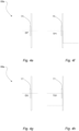
- the primary hole 83 defines a direct primary flow path DP, while each of the first primary channels 99 together with the primary hole 83 and the first primary cavity 95 defines a respective first transferred primary flow path TP1.
- the secondary hole 85 defines a direct secondary flow path DS, while each of the first secondary channels 101 together with the secondary hole 85 and the first secondary cavity 97 defines a respective first transferred secondary flow path TS1.
- the distribution arrangement 69a further comprises an annular primary hole gasket 103, which extends around the primary hole 83 and seals against the primay sub-surface 87, and an annular secondary hole gasket 105, which extends around the secondary hole 85 and seals against the secondary sub-surface 91, of the front surface 89 of the base portion 71.
- the distribution arrangement 69a comprises an annular first primary cavity gasket 107, which extends around the first primary cavity 95 and seals against the back surface 93 of the base portion 71, and an annular first secondary cavity gasket 109, which extends around the first secondary cavity 97 and seals against the front surface 89 of the base portion 71.
- a bar engagement recess 111 is provided in the slab 73 of the distribution arrangement 69a.
- the bar engagement recess 111 extends from an outer edge 113 of the slab 73 and it is arranged to receive a bar for supporting the heat transfer plates 5x, 5 of the device 1, which bar is not illustrated herein.
- the upper distribution arrangement 69a is further provided with snap fitting means 115 in the form of essentially L-shaped projections projecting from the front surface 79 of the slab 73.
- snap fitting means 115 are equidistantly positioned around each of the primary and secondar holes 83 and 85 within corresponding recesses 117 formed in the cylinders 75 and 77.
- the snap fitting means 115 and the cylinders 75 and 77 are arranged to project through two of the third, fifth, fourth and sixth portholes 19, 21, 29 and 31 of two adjacent ones of the heat transfer plates 5 of the device 1 forming between them one of the second interspaces I2.
- the front surface 79 of the slab 73 of the upper distribution arrangement 69a is arranged to face an inner heat transfer plate 5' of the two adjacent heat transfer plates 5 and the first secondary cavity gasket 109 is arranged to abut the inner heat transfer plate 5' around one of the first and second transfer holes 25 and 35 thereof.
- the heat transfer plates 5 are provided with locking means 119 which are equidistantly positioned around the third, fifth, fourth and sixth portholes 19, 21, 29 and 31.
- the snap fitting means 115 of the upper distribution arrangement 69a are arranged to interlock with a respective one of the locking means 119 of an outer heat transfer plate 5" of the two adjacent heat transfer plates 5 so as to connect with the two adjacent heat transfer plates 5', 5" and the sealing arrangement S arranged between them and form an electrolyzer cell EC.
- the lower distribution arrangement 69b is similar to the upper distribution arrangement 69b except for as regards the extension of the first primary channels 99 and the first secondary channels 101.
- each of the first primary channels 99 extend from a respective opening (not illustrated) in the second half 88 of the inner wall 84 enclosing the primary hole 83.
- each of the first secondary channels 101 extend from a respective opening (not illustrated) in the second half 88 of the inner wall 84 enclosing the secondary hole 85.
- the upper and lower distribution arrangements could instead be identical resulting in a device containing one type of distribution arrangements only.
- each of the heat transfer plates 5 engages with a field gasket part 41, an upper distribution arrangement 69a and a lower distribution arrangement 69b on the back side 9, and with a sealing arrangement S on the front side 7.
- the field gasket parts 41 and the sealing arrangements S are, at least partly, arranged in grooves of the heat transfer plates 5, which are not illustrated or further described herein.
- the four annular ring sealing parts 47 of the sealing arrangement S enclose a respective one of the first, second, seventh and eight portholes 17, 27, 23 and 33 of the heat transfer plate 5.
- the field gasket part 41 encloses the first, second, seventh and eight portholes 17, 27, 23 and 33 of the heat transfer plate 5.
- the back surface 81 of the slab 73 of each of the upper and lower distribution arrangements 69a and 69b faces the heat transfer plate 5 with the primary holes 83 and the secondary holes 85 of the upper and lower distribution arrangements 69a and 69b aligned with a respective one of the third, fourth, fifth and sixth portholes 19, 29, 21 and 31 of the heat transfer plate 5 and the first primary cavity gaskets 107 abutting the heat transfer plate 5 around a respective one of the first and second transfer holes 25 and 35 thereof.
- the cylinders 75 and 77 of the upper and lower distribution arrangements 69a and 69b project through the two adjacent heat transfer plates 5 arranged on the front surface 79 of the slab 73 so as to abut the back surface 93 of the base portion 71 of the adjacent upper and lower distribution arrangements 69a and 69b.
- Fig. 6 illustrates, in a highly simplified way, what it looks like when several (here four) electrolyzer cells EC engage properly with each other in the device 1.
- the primary hole gasket 103 and the secondary hole gasket 105 of an upper distribution arrangement 69a' seal against the back surface 93 of the base portion 71, around the holes h, of another upper distribution arrangement 69a
- the primary hole gasket 103 and the secondary hole gasket 105 of the upper distribution arrangement 69a” seal against the back surface 93 of the base portion 71, around the holes h, of yet another upper distribution arrangement 69a′′′, etc.
- the upper distribution arrangements 69a just like the lower distribution arrangements 69b, and more particularly the cylinders 75 and 77 thereof, form two insulated tunnels or ports p (only one of them illustrated in Fig. 6 ) through the device 1, more particularly a second primary inlet port 57p, a second secondary inlet port 57s, a second primary outlet port 59p and a second secondary outlet port 59s, which will be further discussed below.
- the heat transfer plates 5 and 5x and the interposed field gasket parts 41 and sealing arrangements S are compressed between the frame plates F so as to form the first and second flow channels C1 and C2 and also port means for conveying first and second fluids through the device 1.
- the heat transfer plates 5 of each of the pairs such as the heat transfer plates 5b and 5c
- abut each other in contact areas while contact between adjacent pairs of heat transfer plates 5, such as the heat transfer plates 5c and 5d, is prevented by the presence of the sealing arrangements S between the plate pairs. This separation or insulation between the plate pairs is necessary for the device 1 to work properly for electrolysis, which will be further discussed below.
- the port means comprise first inlet port means 53 and first outlet port means 55 for the first fluid and second inlet port means 57 and second outlet port means 59 for the second fluid.
- the first inlet port means 53 comprises a first primary inlet port 53p and a first secondary inlet port 53s
- the first outlet port means 55 comprises a first primary outlet port 55p and a first secondary outlet port 55s
- the second inlet port means 57 comprises the second primary inlet port 57p and the second secondary inlet port 57s
- the second outlet port means 59 comprises the second primary outlet port 59p and the second secondary outlet port 59s.
- the first fluid which is a cooling fluid, for example deionized water
- the first inlet means 61 comprises a first primary inlet 61p and a first secondary inlet 61s
- the first outlet means 63 comprises a first primary outlet 63p and a first secondary outlet 63s.
- the second fluid which is an electrolyte, for example a mixture of water and an alkaline agent, such as potassium hydroxide
- the second inlet means 65 comprises a second primary inlet 65p and a second secondary inlet 65s
- the second outlet means 67 comprises a second primary outlet 67p and a second secondary outlet 67s.
- a first fluid path P1 for conveying the first fluid through the device 1 comprises a first primary fluid path P1p and a first secondary fluid path P1s.
- the first primary fluid path P1p extends from the first primary inlet 61p, into the first primary inlet port 53p, through the first flow channels C1, into the first primary outlet port 55p and to the first primary outlet 63p.
- the first secondary fluid path P1s extends from the first secondary inlet 61s, into the first secondary inlet port 53s, through the first flow channels C1, into the first secondary outlet port 55s and to the first secondary outlet 63s.
- a second fluid path P2 for conveying the second fluid through the device 1 comprises a second primary fluid path P2p, which comprises the direct primary flow path DP and the first transferred primary flow paths TP1 ( Figs. 4e and 4f ) through each of the upper and lower distribution arrangements 69a and 69b, and a second secondary fluid path P2s, which comprises the direct secondary flow path DS and the first transferred secondary flow paths TS1 ( Figs. 4g and 4h ) through each of the upper and lower distribution arrangements 69a and 69b.
- the second primary fluid path P2p extends from the second primary inlet 65p, through the second primary inlet port 57p, i.e.
- the second secondary fluid path P2s extends from the second secondary inlet 65s, through the second secondary inlet port 57s, i.e. through the lower distribution arrangements 69b along the direct secondary flow path DS, through the lower distribution arrangements 69b and into the first interspaces I1 outside the first flow channels C1 along the first transferred secondary flow paths TS1, through the respective second transfer hole 35 of every second one of the heat transfer plates, i.e. plates 5b, 5d,..., into the second secondary sub channels C2S, through the second secondary sub channels C2S, through the respective first transfer hole 25 of every second one of the heat transfer plates, i.e.
- the first fluid i.e. the cooling fluid
- the second fluid i.e. the electrolyte
- the ports 53s, 53p, 55s and 55p are arranged on a larger distance from a longitudinal center plane P of the device 1 than the ports 57p, 57s, 59p and 59s. This means that the cooling fluid is conveyed on the outside of the electrolyte.
- a method for electrolysis is performed by means of the device 1.
- the method comprises the step of applying a current to the device 1 to turn every second one of the heat transfer plate of the device 1, including the heat transfer plates 5a and 5c, into anodes and the rest of the heat transfer plates of the device 1, including the heat transfer plates 5b and 5d, into cathodes.
- sealing arrangements S insulating between the heat transfer plates 5 are arranged in the second interspaces I2 of the device 1, i.e. between the heat transfer plates 5a and 5b, and between the heat transfer plates 5c and 5d, etc., and split the second flow channels C2 into second primary sub channels C2P and second secondary sub channels C2S.
- the ports 57p, 57s, 59p and 59s for the second fluid i.e. the electrolyte, are "lined" with plastic which minimizes the risk of short circuits between the heat transfer plates 5, which short circuits could cause malfunctioning of the device 1.
- the method comprises the step of feeding a first part of the second fluid into the the first interspaces I1 outside the first flow channels C1 and through the first transfer holes 25 of the heat transfer plates 5a, 5c, etc., into the second primary sub channels C2P, and feeding a second part of the second fluid into the the first interspaces I1 outside the first flow channels C1 and through the second transfer holes 35 of the heat transfer plates 5b, 5d, etc., into the second secondary sub channels C2S.
- the method comprises the step of feeding the first and second parts of the second fluid through the second flow channels C2, whereby water in the electrolyte is split into hydrogen and oxygen and a primary fraction is formed in the second primary sub channels C2P and a secondary fraction is formed in the second secondary sub channels C2S, the primary fraction containing more oxygen and less hydrogen than the second fraction.
- the primary fraction of the second fluid is fed through the second transfer holes 35 of the heat transfer plates 5a, 5c, etc. into the first interspaces I1 outside the first flow channels C1, while the secondary fraction of the second fluid is fed through the first transfer holes 25 of the heat transfer plates 5b, 5d, etc. into the first interspaces I1 outside the first flow channels C1.
- the primary and secondary fractions are separately discharged from the device 1 via the second primary outlet 67p and the second secondary outlet 67s, respectively.
- heat is generated.
- the method comprises the step of feeding the first fluid, i.e. the deionized water, through the first flow channels C1, i.e. on both sides of the electrolysis channels C2, to effectively and uniformly divert the heat generated through the electrolysis from the device 1.
- the primary and secondary fractions will typically contain a mixture of liquid and gas.
- the gas may be separated from the liquid already inside the second primary outlet port 59p and the second secondary outlet port 59s, which may improve the final gas-liquid separation of the primary and secondary fractions.
- second fluid is referred to as second fluid even if its characteristics changes when it is fed through the device, and that both the primary fraction and the secondary fraction of the second fluid are referred to as second fluid even if their separate compositions vary and differ from each other and from the original second fluid.
- Figs. 7a-7d illustrate an upper distribution arrangement 121a according to an alternative embodiment of the invention.
- the upper distribution arrangements 69a and 121a are quite similar. The main difference between them is as follows.
- the first primary cavity 95 and the first secondary cavity 97 of the upper distribution arrangement 121a are aligned with each other, i.e. arranged directly opposite one another in the back surface 93 and the front surface 89 of the base portion 71.
- the first primary channels 99 extend between the back surface 81 of the slab 73 and the intermediate extension plane IP while the first secondary channels 101 extend between the front surface 79 of the slab 73 and the intermediate extension plane IP, which allows them to cross each other, as is illustrated in Fig. 7d .
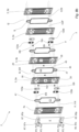
- Fig. 8a illustrates a part of another device 2 used for producing hydrogen through electrolysis.
- the device 2 comprises a stack 3 (only partly illustrated) of heat transfer plates 5 of first and second types of which one is separately illustrated in Fig. 9 .
- a first end portion 11 of the heat transfer plate 5 comprises a first porthole 17, a third porthole 19 a fifth porthole 21 and a first transfer hole 25, while a second end portion 15 of the heat transfer plate 5 comprises a second porthole 27, a fourth porthole 29, a sixth porthole 31 and a second transfer hole 35.
- Every second one of the heat transfer plates 5 in the stack 3 is of the first type illustrated in figure 9 , while the rest of the heat transfer plates 5 in the stack 3 are of the second type which is similar to the first type except for that it has the first and second transfer holes 25 and 35 arranged on the opposite side of the longitudinal center axis L.
- the heat transfer plates 5 of the device 2 define first interspaces I1 and second interspaces I2.
- An annular field gasket part 41 is arranged within each of the first interspaces I1 to define a first flow channel C1 therein.
- Arranged within each of the first interspaces I1 are also two upper distribution arrangements 123a and two lower distribution arrangement 123b which are all similar.
- An annular field sealing part 43 is arranged within each of the second interspaces I2 to define a second flow channel C2 therein.
- a membrane 45 within each of the second interspaces I2 splits the second flow channel C2 in a second primary sub channel C2P and a second secondary sub channel C2S.
- the field sealing part 43 and the separation means comprising the membrane 45 are parts of a sealing arrangement S which also comprises two annular ring sealing parts 47 formed integrally with the field sealing part 43 and an insulating rubber sheet (not illustrated herein).
- the rubber sheet extends on an outside of the field sealing part 43 and the ring sealing parts 47 and is arranged to prevent contact between the heat transfer plates arranged on the opposite sides of the rubber sheet.
- the field gasket part 41 comprises first and second long side portions Is1 and Is2, and first and second short side portions ss1 and ss2 connecting the first and second long side portions Is1 and Is2 at a first end E1 and a second end E2, respectively, of the field gasket part 41.
- the field gasket part 41 or more particularly the first short side portion ss1 thereof, is bent so as to extend between the two upper distribution arrangements 123a.
- the field gasket part 41, or more particularly the second short side portion ss2 thereof is bent so as to extend between the lower distribution arrangements 123b.
- One of the upper distribution arrangement 123a is separately illustrated in Figs. 11a and 11b . It comprises a base portion 71 consisting of a slab 73 and a cylinder 77. A hole h extends through the slab 73 and the cylinder 77 project from a front surface 79 of the slab 73 and enclose the hole h to define a secondary hole 85 through the base portion 71. A free end surface of the cylinder 77 forms an elevated annular secondary sub-surface 91 of a front surface 89 of the base portion 71.
- the base portion 71 comprises a non-through first secondary cavity 97 extending through the front surface 89, of the base portion 71.
- the base portion 71 further comprises a plurality of first secondary channels 101 (one of which is schematically illustrated with a dashed line) extending in an intermediate extension plane located halfway between the front surface 79 and a back surface 81 of the slab 73.
- Each of the first secondary channels 101 connects the secondary hole 85 and the first secondary cavity 97.
- the distribution arrangement 123a further comprises an annular secondary hole gasket 105, which extends around the secondary hole 85 and seals against the secondary sub-surface 91, and an annular first secondary cavity gasket 109, which extends around the first secondary cavity 97 and seals against the front surface 89 of the base portion 71.
- the two annular ring sealing parts 47 of the sealing arrangement S, and the field gasket part 41 enclose the first and second portholes 17 and 27 of each of the heat transfer plates 5 on opposite sides thereof.
- the upper distribution arrangements 123a just like the lower distribution arrangements, are so arranged that one of them faces the heat transfer plates 5a, 5c, etc. with the back surface 81 of the slab 73, and the other one with the front surface 79 of the slab 73.
- the secondary holes 85 of the upper and lower distribution arrangements 123a and 123b are aligned with a respective one of the third, fourth, fifth and sixth portholes 19, 21, 29 and 31. Further, the first secondary cavities 97 of one of the upper and one of the lower distribution arrangements 123a and 123b are aligned with, with the corresponding first secondary cavity gasket 109 surrounding, a respective one of the first and second transfer holes 25 and 35.
- each of the upper and lower distribution arrangements 123a and 123b projects, with the cylinder 77 and the gasket 105, through the heat transfer plate 5 facing the front surface 79 of the slab 73 and the next heat transfer plate 5 so as to abut the next upper and lower distribution arrangements 123a and 123b and form a total of four insulated ports through the device 2, more particularly a second primary inlet port 57p, a second secondary inlet port 57s, a second primary outlet port 59p and a second secondary outlet port 59s.
- the device 2 comprises port means for conveying first and second fluids through the device 2.
- the port means comprise first inlet port means 53 and first outlet port means 55 for the first fluid and second inlet port means 57 and second outlet port means 59 for the second fluid.
- the first inlet port means 53 do not comprise first primary and secondary inlet ports, but only one single inlet port.
- the first outlet port means 55 do not comprise first primary and secondary outlet ports, but only one single outlet port.
- the second inlet port means 57 comprises the second primary inlet port 57p and the second secondary inlet port 57s
- the second outlet port means 59 comprises the second primary outlet port 59p and the second secondary outlet port 59s.
- the first fluid is fed into the device 2 via first inlet means 61 and out of the device 2 via first outlet means 63.
- the first inlet means 61 do not comprise first primary and secondary inlets, but only one single inlet.
- the first outlet means 63 do not comprise first primary and secondary outlets, but only one single outlet.
- the second fluid is fed into the device 2 via second inlet means 65 and out of the device 1 via second outlet means 67.
- the second inlet means 65 comprises a second primary inlet 65p and a second secondary inlet 65s
- the second outlet means 67 comprises a second primary outlet 67p and a second secondary outlet 67s.
- first fluid path P1 for conveying the first fluid through the device 2.
- first fluid path P1 extends from the first inlet 61, into the first inlet port 53, through the first flow channels C1, into the first outlet port 55 and to the first outlet 63.
- a second fluid path P2 for conveying the second fluid through the device 1 comprises a second primary fluid path P2p and a second secondary fluid path P2s.
- a second fluid path P2 for conveying the second fluid through the device 2 comprises a second primary fluid path P2p, which comprises the direct secondary flow path DS and the first transferred secondary flow paths TS1 through, as seen from the frame plate F, each of the right upper and right lower distribution arrangements 123a and 123b, and a second secondary fluid path P2s, which comprises the direct secondary flow path DS and the first transferred secondary flow paths TS1 through, as seen from the frame plate F, each of the left upper and lower distribution arrangements 123a and 123b.
- the second primary fluid path P2p extends from the second primary inlet 65p, through the second primary inlet port 57p, i.e.
- the second secondary fluid path P2s extends from the second secondary inlet 65s, through the second secondary inlet port 57s, i.e. through the left lower distribution arrangements 123b along the direct secondary flow path DS, through the left lower distribution arrangements 123b and into the first interspaces I1 outside the first flow channels C1 along the first transferred secondary flow paths TS1, through the respective second transfer hole 35 of every second one of the heat transfer plates, i.e. plates 5b, 5d,..., into the second secondary sub channels C2S, through the second secondary sub channels C2S, through the respective first transfer hole 25 of every second one of the heat transfer plates, i.e.
- the first fluid is conveyed through the device 2 in the ports 53 and 55, while the second fluid is conveyed through the device 2 in the ports 57p, 57s, 59p and 59s.
- the ports 57p, 57s, 59p and 59s are arranged on a larger distance from a longitudinal center plane P of the device 2 than the ports 53 and 55. This means that the second fluid is conveyed on the outside of the first fluid.
- Figs. 12a and 12b schematically illustrates an upper distribution arrangement 125a, from a front and a back, respectively, according to an alternative embodiment of the invention, which may be used in connection with a heat transfer plate 5 according to Fig. 9 .
- the upper distribution arrangement 125a comprises a plastic base portion 71 provided with a primary hole 83, a secondary hole 85, a first primary cavity 95, a first secondary cavity 97, first primary channels 99 (one of them schematically illustrated with dashed line) and first secondary channels 101 (one of them schematically illustrated with dashed line).
- the upper distribution arrangement 125a comprises a non-through second primary cavity 96 which extends through the back surface 93 of the base portion 71, and a non-through second secondary cavity 98 which extends through a front surface 89 of the base portion 71.
- a plurality of second primary channels 104 (one of them schematically illustrated with dashed line) connect the primary hole 83 and the second primary cavity 96 so as to form a respective second transferred primary flow path TP2 through the upper distribution arrangement 125a.
- a plurality of second secondary channels 106 (one of them schematically illustrated with dashed line) connect the secondary hole 85 and the second secondary cavity 98 so as to form a respective second transferred secondary flow path TS2 through the upper distribution arrangement 125a.
- All the first primary channels 99, the second primary channels 104, the first secondary channels 101 and the second secondary channels 106 extend in an intermediate plane extending halfway between the front and back surfaces 79 and 81 of a slab 73 of the base portion 71.
- the first primary channels 99 and the second primary channels 104 extend on one side of a partition wall W while the first secondary channels 101 and the second secondary channels 106 extend on another side of the partition wall W.
- the first and second primary cavities 95 and 96 are arranged on opposite sides of a longitudinal center axis I1 of the upper distribution arrangement 125a so as to enable a uniform distribution of the second fluid in the second primary sub channels C2P of a device similar to the device 2.
- the first and second secondary cavities 97 and 98 are arranged on opposite sides of the longitudinal center axis I1 of the upper distribution arrangement 125a so as to enable a uniform distribution of the second fluid in the second secondary sub channels C2S of a device similar to the device 2.
- Figs. 13a and 13b schematically illustrates an upper distribution arrangement 127a, from a front and a back, respectively, according to an alternative embodiment of the invention.
- the upper distribution arrangements 125a and 127a are quite similar. The main difference between them is as follows.
- the first primary cavity 95 and second secondary cavity 98 of the upper distribution arrangement 127a are aligned with each other, i.e. arranged directly opposite one another in the back surface 93 and the front surface 89 of the base portion 71.
- the second primary cavity 96 and first secondary cavity 97 of the upper distribution arrangement 127a are aligned with each other.
- the first primary channels 99 and the second primary channels 104 extend between the back surface 81 of the slab 73 and the intermediate extension plane while the first secondary channels 101 and the second secondary channels 106 extend between the front surface 79 of the slab 73 and the intermediate extension plane.
- the upper distribution arrangements 125a and 127a comprises gaskets, etc., necessary for their proper functioning, even if not illustrated or further discussed herein.
- the cylinders 75 and 77 of the upper distribution arrangement 69a have a height enough for the the cylinders 75 and 77 to be able to project through two heat transfer plates 5.
- the upper distribution arrangement 69a could instead be so configured that the two cylinders 75 and 77 are half as high, and that two additional equally high cylinders, arranged aligned with a respective one of the cylinders 75 and 77, project from the the back surface 81 of the slab 73.
- These four cylinders could be arranged to pairwise project through the heat transfer plates 5 arranged on the opposite sides of the upper distribution arrangement 69a.
- the secondary and/or primary holes of the distribution arrangements need not be circular but may have any suitable form, such as oval or polygonal.
- the cavity or cavities of the distribution arrangement need not be elongate but may have any suitable form, such as circular.
- the distribution arrangement may be comprised in a device used for another type of electrolysis than alkaline water electrolysis, for example chlor-alkali electrolysis. Further, the distribution arrangement may be comprised in a device for other applications than electrolysis, for example a device in the form of a fuel cell. It should be stressed that the attributes first, second, third, ... , primary, secondary, upper, lower, and A, B, C, ... , etc. are used herein just to distinguish between species and not to express any kind of mutual order between, or attribute any special characteristics to, the species. Thus, as is clear from the above, a distribution arrangement according to the invention may comprise a secondary hole and a first secondary cavity but no primary hole and no first primary cavity, etc.
Landscapes
- Engineering & Computer Science (AREA)
- Chemical & Material Sciences (AREA)
- Organic Chemistry (AREA)
- Electrochemistry (AREA)
- Materials Engineering (AREA)
- Metallurgy (AREA)
- Chemical Kinetics & Catalysis (AREA)
- Physics & Mathematics (AREA)
- Thermal Sciences (AREA)
- Mechanical Engineering (AREA)
- General Engineering & Computer Science (AREA)
- Inorganic Chemistry (AREA)
- Heat-Exchange Devices With Radiators And Conduit Assemblies (AREA)
Abstract
Description
- The invention relates to a distribution arrangement configured to be positioned between two corrugated heat transfer plates. The heat transfer plates and the distribution arrangement may be comprised in a device used for a heat generating process, such as electrolysis.
- Electrolysis is a well known process of using electricity to chemically decompose an electrolyte. For example, electrolysis can be used to split water confined in an electrolyte into hydrogen and oxygen. During electrolysis, heat may be generated, which heat may have to be diverted for maintained electrolysis efficiency.
-
EP 4012070 discloses a heat exchanger comprising a stack of heat transfer plates. The heat exchanger is adapted for connection to an electrolyzing device such that fluids circulating in the electrolyzing device are made to pass the heat exchanger for regulation of their temperatures. Typically, the temperature of the fluids gradually increases inside the electrolyzing device. Thus, the heat exchanger receives fluids of relatively high temperature from the electrolyzing device and delivers fluids of relatively low temperature to the electrolyzing device, which means that there will be a temperature difference across the electrolyzing device. This may result in an uneven and non-optimal electrolysis process inside the electrolyzing device. The heat exchanger inEP 4012070 is a so called plate-and-shell heat exchanger. Several other types of heat exchangers exist, for example so-called plate heat exchangers. A plate heat exchanger typically comprises a number of corrugated heat transfer plates arranged aligned in a stack or pack. Sealings between the heat transfer plates define parallel flow channels between the heat transfer plates, one flow channel between each pair of adjacent heat transfer plates. Two fluids of initially different temperatures can be fed alternately through every second flow channel for transferring heat from one fluid to the other. - An object of the present invention is to provide a distribution arrangement for positioning between two corrugated heat transfer plates so as to enable realization of a reliable and mechanically uncomplicated device comprising said heat transfer plates as part of a stack of corrugated heat transfer plates forming alternately arranged first and second plate interspaces, which device may be used for a heat generating process, such as electrolysis, and which device may allow a more uniform and effective cooling of a fluid, such as an electrolyte, and the products formed therefrom, so as to enable a maintained high process efficiency. The basic concept of the invention is to offer a distribution arrangement that may be arranged in the first interspaces dedicated for cooling, such that a heat generating process can be effectively maintained in the second interspaces, which distribution arrangement allows use of the first interspaces to feed fluid into, and out of, the second interspaces. Thus, the basic concept of the invention is to offer a distribution arrangement that enables a device for performing a heat generating process, such as electrolysis, which device, at the same time, may function as a traditional heat exchanger so as to provide cooling "integrated" in the heat generating process.
- The distribution arrangement may be used in a device for production of hydrogen.
- Since the distribution arrangement according to the invention is not arranged for use on its own, but as a component of a device as described above, the advantages of different features and embodiments of the distribution arrangement appears first when the distribution arrangement is installed in the device.
- As said above, the distribution arrangement may be used in a device of the above described type to feed fluid, here a second fluid, into and out of a second interspace via a first interspace. Unless stated otherwise, the distribution arrangement as used for feeding the second fluid into the second interspace is described in the rest of this "Summary". Then, the distribution arrangement is arranged for flow diversion in an advantageous way, as will be further describe below. The distribution arrangement as used for feeding the second fluid out of the second interspace is instead arranged for flow collection in a corresponding advantageous way, which will be further discussed in the "Detailed Description".
- A distribution arrangement according to the invention is for positioning between two corrugated heat transfer plates which may be of the same or different types. It comprises a base portion which includes a slab having opposing front and back surfaces arranged to face a respective one of the heat transfer plates. An intermediate extension plane of the slab extends between the front and back surfaces of the slab. A front surface and a back surface of the base portion comprises at least a part of the front surface and the back surface, respectively, of the slab. The base portion comprises a through secondary hole which extends through the front and back surfaces of the base portion so as to form a direct secondary flow path through the base portion. The base portion also comprises a non-through first secondary cavity which extends through the front surface of the base portion. Further, the base portion comprises at least one first secondary channel which extends inside the slab. Said at least one first secondary channel connects the secondary hole and the first secondary cavity to form a first transferred secondary flow path through the base portion. An annular secondary sub-surface of the front surface of the base portion encloses the secondary hole.
- It should be stressed that, herein, "annular" and "ring" is not necessarily circular but may be any "closed" shape, such as oval, polygonal or any combination thereof.
- When the distribution arrangement is properly arranged between the heat transfer plates, the intermediate extension plane of the slab may extend essentially parallel to the heat transfer plates.
- The intermediate extension plane of the slab may extend essentially parallel to the front and back surfaces of the slab. The intermediate extension plane may, or may not, extend halfway between the front and back surfaces of the slab.
- Said at least one first secondary channel which extends inside the slab may, or may not, extend essentially parallel to the intermediate extension plane of the slab.
- In that the first secondary cavity is non-through, it will extend only partly through the base portion, i.e. not through the back surface of the base portion.
- Thus, there is a direct secondary flow path, defined by the secondary hole, and a first transferred secondary flow path, defined by the secondary hole, the first secondary channel and the first secondary cavity, for a second fluid through the base portion. This makes it possible for the distribution arrangement to divide a first secondary sub flow from a second secondary fluid flow. Thereby, if the distribution arrangement is arranged in a first interspace of a device as described above, it may convey the first secondary sub flow of the second fluid into an adjacent second interspace via the first interspace, as will be further described below.
- The distribution arrangement can be made of one ore more materials. For example, the base portion of the distribution arrangement, and particularly the front and back surfaces of the base portion, may be made of one or more insulating materials. Thereby, the base portion may prevent short circuiting within a device for performing a heat generating process, such as electrolysis, which short circuiting could cause malfunctioning of the device.
- The distribution arrangement may further comprise a secondary hole gasket. The secondary hole gasket may enclose the secondary hole and seal against the secondary sub-surface of the front surface of the base portion. The secondary hole gasket may enable a tight seal between the secondary sub-surface and another surface, which surface may be comprised in another distribution arrangement according to the invention. Additionally/alternatively, the distribution arrangement may comprise a first secondary cavity gasket. The first secondary cavity gasket may enclose the first secondary cavity and seal against the front surface of the base portion. The first secondary cavity gasket may enable a tight seal between the front surface of the base portion and another surface, which surface may be comprised in a heat transfer plate.
- The distribution arrangement may be so designed that the secondary sub-surface is elevated in relation to the rest of the front surface of the base portion. Thereby, the base portion will have an increased thickness around the secondary hole. Such a design may enable for the distribution arrangement to project through a heat transfer plate to prevent short circuiting within a device for performing a heat generating process, such as electrolysis.
- The base portion may further comprise a through primary hole. The primary hole may extend through the front and back surfaces of the base portion so as to form a direct primary flow path through the base portion. The base portion may further comprise a non-through first primary cavity which extends through the back surface of the base portion, and at least one first primary channel extending inside the slab. Said at least one first primary channel may connect the primary hole and the first primary cavity to form a first transferred primary flow path through the base portion. An annular primary sub-surface of the front surface of the base portion may enclose the primary hole.
- Said at least one first primary channel which extends inside the slab may, or may not, extend essentially parallel to the intermediate extension plane of the slab.
- In that the first primary cavity is non-through, it will extend only partly through the base portion, i.e. not through the front surface of the base portion.
- Thus, there is a direct primary flow path, defined by the primary hole, and a first transferred primary flow path, defined by the primary hole, the first primary channel and the first primary cavity, for the second fluid through the base portion. This makes it possible for the distribution arrangement to divide a first primary sub flow from a second primary fluid flow. Thereby, if the distribution arrangement is arranged in a first interspace of a device as described above, it may it may convey the first primary sub flow of the second fluid into an adjacent second interspace via the first interspace, as will be further described below.
- The distribution arrangement may further comprise a primary hole gasket. The primary hole gasket may enclose the primary hole and seal against the primary sub-surface of the front surface of the base portion. The primary hole gasket may enable a tight seal between the primary sub-surface and another surface, which surface may be comprised in another distribution arrangement according to the invention. Additionally/alternatively, the distribution arrangement may comprise a first primary cavity gasket. The first primary cavity gasket may enclose the first primary cavity and seal against the back surface of the base portion. The first primary cavity gasket may enable a tight seal between the back surface of the base portion and another surface, which surface may be comprised in a heat transfer plate.
- The distribution arrangement may be so designed that the primary sub-surface is elevated in relation to the rest of the front surface of the base portion. Thereby, the base portion will have an increased thickness around the primary hole.
- The distribution arrangement may be such that the first secondary cavity is aligned with the first primary cavity. Then, a normal axis extending perpendicular to the intermediate extension plane of the slab may extend through both the first secondary cavity and the first primary cavity. Such a configuration may be advantageous in that it enables for said at least one first secondary channel and said at least one first primary channel to cross each other.
- Alternatively, the distribution arrangement may be such that the first secondary cavity is displaced from the first primary cavity. Then, a normal axis extending perpendicular to the intermediate extension plane of the slab may not extend through both the first secondary cavity and the first primary cavity. Such a configuration may be advantageous in that it enables for said at least one first secondary channel, as well as for said at least one first primary channel, to extend at any level between the front and back surfaces of the slab.
- The distribution arrangement may be so designed that said at least one first secondary channel extends between the front surface of the slab and the intermediate extension plane of the slab. Further, said at least one first primary channel may extend between the back surface of the slab and the intermediate extension plane of the slab. Such a configuration may be advantageous in that it enables for said at least one first secondary channel and said at least one first primary channel to cross each other.
- The base portion of the distribution arrangement may comprise a non-through second secondary cavity which extends through the front surface of the base portion, and at least one second secondary channel extending inside the slab. Said at least one second secondary channel may connect the secondary hole and the second secondary cavity to form a second transferred secondary flow path through the base portion. Additionally/alternatively, the base portion may comprise a non-through second primary cavity which extends through the back surface of the base portion, and at least one second primary channel extending inside the slab. Said at least one second primary channel may connect the primary hole and the second primary cavity to form a second transferred primary flow path through the base portion.
- Said at least one second secondary channel and/or said at least one second primary channel which extend inside the slab may, or may not, extend essentially parallel to the intermediate extension plane of the slab.
- In that the second secondary cavity is non-through, it will extend only partly through the base portion, i.e. not through the back surface of the base portion.
- In that the second primary cavity is non-through, it will extend only partly through the base portion, i.e. not through the front surface of the base portion.
- Thus, besides for the direct secondary flow path and the first transferred secondary flow path, there may be a second transferred secondary flow path, defined by the secondary hole, the second secondary channel and the second secondary cavity, for the second fluid through the base portion. This makes it possible for the distribution arrangement to divide a second secondary sub flow from the second secondary fluid flow. Thereby, if the distribution arrangement is arranged in a first interspace of a device as described above, it may it may convey the second secondary sub flow of the second fluid into an adjacent second interspace via the first interspace. The first and second secondary sub flows may be conveyed into the second interspace at different positions which may improve the distribution of the second fluid in the second interspace.
- Further, besides for the direct primary flow path and the first transferred primary flow path, there may be a second transferred primary flow path, defined by the primary hole, the second primary channel and the second primary cavity, for the second fluid through the base portion. This makes it possible for the distribution arrangement to divide a second primary sub flow from the second primary fluid flow. Thereby, if the distribution arrangement is arranged in a first interspace of a device as described above, it may it may convey the second primary sub flow of the second fluid into an adjacent second interspace via the first interspace. The first and second primary sub flows may be conveyed into the second interspace at different positions which may improve the distribution of the second fluid in the second interspace.
- The distribution arrangement may be so designed that the first secondary cavity and the second secondary cavity are aligned with the second primary cavity and the first primary cavity, respectively. Such a configuration may be advantageous in that it enables for said at least one first secondary channel and said at least one second primary channel to cross each other, and for said at least one second secondary channel and said at least one first primary channel to cross each other.
- Alternatively, distribution arrangement may be so designed that the first secondary cavity and the second secondary cavity are displaced from the second primary cavity and the first primary cavity. Such a configuration may be advantageous in that it enables for said at least one first secondary channel, said at least one second secondary channel, said at least one first primary channel and said at least one second primary channel to extend at any level between the front and back surfaces of the slab.
- The distribution arrangement may be such that said at least one first secondary channel and said at least one second secondary channel extend between the front surface of the slab and the intermediate extension plane of the slab. Further, said at least one first primary channel and said at least one second primary channel may extend between the back surface of the slab and the intermediate extension plane of the slab. Such a configuration may be advantageous in that it enables for said at least one first secondary channel and said at least one second primary channel to cross each other, and for said at least one second secondary channel and said at least one first primary channel to cross each other.
- The distribution arrangement may be so designed that the slab comprises an inner wall enclosing, i.e. defining, the secondary hole. The inner wall may comprise first and second halves which extend on opposite sides of a hole center plane dividing the secondary hole in half, which hole center plane extends perpendicular to the intermediate extension plane of the slab. The first half of the inner wall of the slab may be arranged further away from the first secondary cavity than the second half of the inner wall of the slab. Said at least one first secondary channel may extend from an opening in the first half of the inner wall of the slab. Such a design may be advantageous when the distribution arrangement is arranged to be used with such an orientation that the first half of the inner wall is arranged above the second halv of the inner wall. Then, such a design may facilitate separation of a gas phase and a liquid phase of the second fluid in the secondary hole, as will be further described below. The primary hole of the distribution arrangement may have a similar construction.
- The slab of the distribution arrangement may be provided with a bar engagement recess. As indicated by the name, the bar engagement recess may be arranged for engagement with a bar of a device as described above, which bar is arranged to support the heat transfer plates of the device. Thus, the bar engagement recess may be used to secure the distribution arrangement, and any heat transfer plate engaging therewith, in the device. The bar engagement recess may be formed as a hole, cavity or hollow through the slab, defined by an annular inner wall of the slab. As another example, the bar engagement recess may extend from an outer edge of the slab, for example from a center portion of the outer edge. The bar engagement recess, which may be insulating, and the first secondary cavity may be arranged on opposite sides of the secondary hole. The recess may have any suitable shape.
- The distribution arrangement may further comprise snap fitting means projecting from the front surface of the slab around said annular secondary sub-surface, and possibly also around said annular primary sub-surface, of the front surface of the base portion. Said snap fitting means may be arranged to engage with locking means of one of said heat transfer plates to attach the distribution arrangement to said one of the heat transfer plates. Such snap fitting means may enable a simple and stable assembly of a device comprising the distribution arrangement and said heat transfer plates.
- Still other objectives, features, aspects and advantages of the invention will appear from the following detailed description as well as from the drawings.
- The invention will now be described in more detail with reference to the appended schematic drawings, in which
-
Figs. 1a and1b are essentially similar perspective views schematically illustrating a part of a device, which comprises a plurality of distribution arrangements according to the invention, in a disassembled state, and different fluid paths through the device, -
Fig. 2 is a schematic plan view of a heat transfer plate of the device inFig. 1a , -
Fig. 3 is a schematic plan view of a part of the device inFig. 1a , -
Fig. 4a is a schematic front plan view of an upper distribution arrangement of the device inFig. 1a , -
Fig. 4b is a schematic back plan view of the upper distribution arrangement inFig. 4a , -
Fig. 4c is a schematic partial perspective view of the upper distribution arrangement inFig. 4a , -
Fig. 4d is a schematic cross sectional view of the upper distribution arrangement inFig. 4a , -
Fig. 4e-4h schematically illustrates different flow paths through the upper distribution arrangement inFig. 4a , -
Fig. 5a is a schematic perspective view of the upper distribution arrangement inFig. 4a , -
Fig. 5b schematically partly illustrates an electrolyzer cell comprising the upper distribution arrangement illustrated inFig. 5a , -
Fig. 6 schematically illustrates engagement between a plurality of electrolyzer cells according toFig. 5b , -
Fig. 7a is a schematic front plan view of an upper distribution arrangement according to an alternative embodiment, -
Fig. 7b is a schematic back plan view of the upper distribution arrangement inFig. 7a , -
Fig. 7c is a schematic cross sectional view of the upper distribution arrangement inFig. 7a , -
Fig. 7d is another schematic cross sectional view of the upper distribution arrangement inFig. 7a , -
Figs. 8a and8b are essentially similar perspective views schematically illustrating a part of a device, which comprises a plurality of distribution arrangements according to another embodiment of the invention, in a disassembled state, and different fluid paths through the device, -
Fig. 9 is a schematic plan view of a heat transfer plate of the device inFig. 8a , -
Fig. 10 is a schematic plan view of a part of the device inFig. 8a , -
Fig. 11a is a schematic front plan view of an upper distribution arrangement of the device inFig. 8a , -
Fig. 11b is a schematic back plan view of the upper distribution arrangement inFig. 11a , -
Fig. 12a is a schematic front plan view of an upper distribution arrangement according to an alternative embodiment, -
Fig. 12b is a schematic back plan view of the upper distribution arrangement inFig. 12a , -
Fig. 12c is a schematic cross sectional view of the upper distribution arrangement inFig. 12a , -
Fig. 13a is a schematic front plan view of an upper distribution arrangement according to another alternative embodiment, and -
Fig. 13b is a schematic back plan view of the upper distribution arrangement inFig. 13a . -
Fig. 1a illustrates a part of adevice 1 used for producing hydrogen through electrolysis, here alkaline water electrolysis. Thedevice 1 comprises a stack 3 (only partly illustrated) of similarheat transfer plates 5 which each has afront side 7 and an opposing backside 9. In thestack 3, theheat transfer plates 5 are flipped in relation to each other, i.e. arrangedfront side 7 tofront side 7 and backside 9 to backside 9 with every second one of theheat transfer plates 5 turned upside down with respect to the rest of theheat transfer plates 5. This means that every second one of theheat transfer plates 5 is rotated 180 degrees around a respective heat transfer plate longitudinal center axis L, and then rotated 180 degrees around a respective heat transfer plate normal axis N (Fig. 2 ), with respect to the rest of theheat transfer plates 5. - One of the
heat transfer plates 5 is separately illustrated inFig. 2 and described in further detail below. It has afirst end portion 11, acenter portion 13 and asecond end portion 15 arranged in succession along the longitudinal center axis L of theheat transfer plate 5, which longitudinal center axis L extends perpendicular to a transverse center axis T of theheat transfer plate 5. Thefirst end portion 11 comprises afirst porthole 17, athird porthole 19, afifth porthole 21, aseventh porthole 23 and afirst transfer hole 25, while thesecond end portion 15 comprises asecond porthole 27, afourth porthole 29, asixth porthole 31, aneighth porthole 33 and asecond transfer hole 35. - As heat transfer plates normally are, the
heat transfer plate 5 is pressed with corrugation patterns of ridges and valleys in relation to a respective central extension plane of theheat transfer plate 5, which central extension plane is parallel to the figure plane ofFig. 2 . The corrugation patterns within different areas of theheat transfer plate 5 are different. For example, thecenter portion 13 is pressed with a corrugation pattern of so-called herringbone type. As another example, anedge portion 37 of theheat transfer plate 5 is pressed with alternately arranged ridges and valleys extending from anouter edge 39 of theheat transfer plate 5. - With reference again to
Fig. 1a , thestack 3 ofheat transfer plates 5 is arranged between two frame plates F, of which only one is illustrated. Theheat transfer plates 5 within thestack 3 are arranged in pairs, wherein heat transfer plates 5b and 5c form one of these pairs, while heat transfer plate 5d forms one of the heat transfer plates of another adjacent one of these pairs. The heat transfer plates of each pair form between them afirst interspace 11. Further, a second interspace I2 is formed between each two adjacent pairs ofheat transfer plates 5. An outerheat transfer plate 5x, which is similar to theheat transfer plates 5 except for that it lacks the first and second transfer holes 25 and 35, is arranged between thestack 3 and the frame plate F visible inFig. 1a to form an additionalfirst interspace 11, denoted I1X, as well as a plate pair, with the heat transfer plate 5a. An additional second interspace I2, denoted I2X, is thus formed between the heat transfer plate 5a and the heat transfer plate 5b. An outer heat transfer plate completely lacking holes may be arranged between thestack 3 and the other frame plate which is not visible inFig. 1a . Further, gaskets, which are not illustrated, may be arranged on the inside of the frame plates F. - An annular
field gasket part 41 of rubber is arranged within each of the first interspaces I1 to define a first flow channel C1 therein. Arranged within each of the first interspaces I1 are also anupper distribution arrangement 69a and alower distribution arrangement 69b. An annularfield sealing part 43 is arranged within each of the second interspaces I2 to define a second flow channel C2 therein. A separation means, which closes a field sealing area enclosed by thefield sealing part 43, comprises a hydroxide ionpermeable membrane 45. Themembrane 45 extends within thefield sealing part 43 and essentially parallel to theheat transfer plates 5 to split the corresponding second flow channel C2 in a second primary sub channel C2P and a second secondary sub channel C2S, which sub channels are parallel and extend on opposite sides of themembrane 45. Thefield sealing part 43 and the separation means comprising themembrane 45 are parts of a sealing arrangement S of rubber (except for the membrane) which also comprises four annularring sealing parts 47 formed integrally with thefield sealing part 43 and an insulating rubber sheet (not illustrated herein). The rubber sheet extends on an outside of thefield sealing part 43 and thering sealing parts 47 and is arranged to prevent contact between the heat transfer plates arranged on the opposite sides of the rubber sheet. - With reference to
Fig. 3 , thefield gasket part 41 encloses a field gasket area A1 having a transverse center axis T1 and a longitudinal center axis L1. The field gasketpart 41 comprises first and second long side portions Is1 and Is2, which extend essentially parallel to the longitudinal center axis L1 of the field gasket area A1, and first and second short side portions ss1 and ss2. The first short side portion ss1 connects the long side portions Is1 and Is2 at a first end E1 of thefield gasket part 41, while the second short side portion ss2 connects the long side portions Is1 and Is2 at a second end E2 of thefield gasket part 41. The first and second short side portions ss1 and ss2 are bulging towards each other so as to form a first recess R1 on an outside of the first short side portion ss1 and a second recess R2 on an outside of the second short side portion ss2. Theupper distribution arrangement 69a is partly arranged within the recess R1 of thefield gasket part 41 while thelower distribution arrangement 69b is partly arranged within the recess R2 of thefield gasket part 41. - The
upper distribution arrangement 69a is separately illustrated inFigs. 4a-4d . It comprises abase portion 71 which is made of an insulating material such as a polymer. Thebase portion 71 consists of a slab, plate ordisc 73 and two similar projections in the shape of thick-walled cylinders slab 73 has opposing front and back surfaces 79 and 81 of which thefront surface 79 is visible inFigs. 4a and 4c and theback surface 81 is visible inFig. 4b . Two holes h extend through theslab 73 on opposite sides of a longitudinal center axis I1 of theupper distribution arrangement 69a. Thecylinders front surface 79 of theslab 73 and enclose a respective one of the holes h through theslab 73 to define aprimary hole 83 and asecondary hole 85, respectively, through thebase portion 71. As illustrated inFig. 4b , theslab 73 comprises twoinner walls 84 enclosing a respective one of the primary andsecondary holes inner walls 84 comprises afirst half 86 and asecond half 88 which extend on opposite sides of a hole center plane CP dividing the primary andsecondary holes Figs. 4a and 4c , a free end surface of thecylinder 75 forms an elevated annularprimary sub-surface 87 of afront surface 89 of thebase portion 71. A free end surface of thecylinder 77 forms an elevated annularsecondary sub-surface 91 of thefront surface 89 of thebase portion 71. Thus, thefront surface 89 of thebase portion 71 comprises thisprimary sub-surface 87 and thissecondary sub-surface 91 and the portion of thefront surface 79 of theslab 73 extending outside thecylinders back surface 93 of thebase portion 71 comprises theback surface 81 of theslab 73. - Further, the
base portion 71 comprises a non-through firstprimary cavity 95 extending through theback surface 93, and a non-through firstsecondary cavity 97 extending through thefront surface 89, of thebase portion 71. As is clear fromFigs. 4a-4d , the firstprimary cavity 95 and the firstsecondary cavity 97 are displaced from each other, i.e. they are arranged on opposite sides of the longitudinal center axis I1 of theupper distribution arrangement 69a.Fig. 4d illustrates a cross section through theupper distribution arrangement 69a at an intermediate extension plane IP of theslab 73, which plane coincides with the figure plane ofFig. 4d and extends halfway between the front and back surfaces 79 and 81 of theslab 73. Further, the intermediate extension plane IP extends perpendicular to the hole center plane CP (Fig. 4b ) of theslab 73. With reference toFig. 4d , thebase portion 71 further comprises a plurality of firstprimary channels 99 and a plurality of firstsecondary channels 101. The firstprimary channels 99 and the firstsecondary channels 101 all extend in the intermediate extension plane IP. Each of the firstprimary channels 99 connects theprimary hole 83 and the firstprimary cavity 95. Each of the firstsecondary channels 101 connects thesecondary hole 85 and the firstsecondary cavity 97. With reference also toFig. 4b , each of the firstprimary channels 99 extend from arespective opening 100 in thefirst half 86 of theinner wall 84 enclosing theprimary hole 83. Similarly, each of the firstsecondary channels 101 extend from arespective opening 102 in thefirst half 86 of theinner wall 84 enclosing thesecondary hole 85. - With reference now also to
Figs. 4e-4h , there are a plurality of different flow paths through thebase portion 71 and theupper distribution arrangement 69a. More particularly, theprimary hole 83 defines a direct primary flow path DP, while each of the firstprimary channels 99 together with theprimary hole 83 and the firstprimary cavity 95 defines a respective first transferred primary flow path TP1. Further, thesecondary hole 85 defines a direct secondary flow path DS, while each of the firstsecondary channels 101 together with thesecondary hole 85 and the firstsecondary cavity 97 defines a respective first transferred secondary flow path TS1. - With reference again to
Figs. 4a-4c , thedistribution arrangement 69a further comprises an annularprimary hole gasket 103, which extends around theprimary hole 83 and seals against theprimay sub-surface 87, and an annularsecondary hole gasket 105, which extends around thesecondary hole 85 and seals against thesecondary sub-surface 91, of thefront surface 89 of thebase portion 71. Further, thedistribution arrangement 69a comprises an annular firstprimary cavity gasket 107, which extends around the firstprimary cavity 95 and seals against theback surface 93 of thebase portion 71, and an annular firstsecondary cavity gasket 109, which extends around the firstsecondary cavity 97 and seals against thefront surface 89 of thebase portion 71. - With reference to
Figs. 4a and 4b , abar engagement recess 111 is provided in theslab 73 of thedistribution arrangement 69a. Thebar engagement recess 111 extends from anouter edge 113 of theslab 73 and it is arranged to receive a bar for supporting theheat transfer plates device 1, which bar is not illustrated herein. - As illustrated in
Figs. 5a and 5b , theupper distribution arrangement 69a is further provided with snap fitting means 115 in the form of essentially L-shaped projections projecting from thefront surface 79 of theslab 73. Four snap fitting means 115 are equidistantly positioned around each of the primary andsecondar holes recesses 117 formed in thecylinders Figs. 1a ,2 and5b , the snap fitting means 115 and thecylinders sixth portholes heat transfer plates 5 of thedevice 1 forming between them one of the second interspaces I2. Further, thefront surface 79 of theslab 73 of theupper distribution arrangement 69a is arranged to face an inner heat transfer plate 5' of the two adjacentheat transfer plates 5 and the firstsecondary cavity gasket 109 is arranged to abut the inner heat transfer plate 5' around one of the first and second transfer holes 25 and 35 thereof. Theheat transfer plates 5 are provided with locking means 119 which are equidistantly positioned around the third, fifth, fourth andsixth portholes upper distribution arrangement 69a are arranged to interlock with a respective one of the locking means 119 of an outerheat transfer plate 5" of the two adjacentheat transfer plates 5 so as to connect with the two adjacentheat transfer plates 5', 5" and the sealing arrangement S arranged between them and form an electrolyzer cell EC. - The
lower distribution arrangement 69b is similar to theupper distribution arrangement 69b except for as regards the extension of the firstprimary channels 99 and the firstsecondary channels 101. With reference toFigs. 4b and 4d , for thelower distribution arrangement 69b, each of the firstprimary channels 99 extend from a respective opening (not illustrated) in thesecond half 88 of theinner wall 84 enclosing theprimary hole 83. Similarly, each of the firstsecondary channels 101 extend from a respective opening (not illustrated) in thesecond half 88 of theinner wall 84 enclosing thesecondary hole 85. In an alternative embodiment, the upper and lower distribution arrangements could instead be identical resulting in a device containing one type of distribution arrangements only. - With reference to
Fig. 1a , in thedevice 1, each of theheat transfer plates 5 engages with afield gasket part 41, anupper distribution arrangement 69a and alower distribution arrangement 69b on theback side 9, and with a sealing arrangement S on thefront side 7. Thefield gasket parts 41 and the sealing arrangements S are, at least partly, arranged in grooves of theheat transfer plates 5, which are not illustrated or further described herein. With reference also toFig. 2 , the four annularring sealing parts 47 of the sealing arrangement S enclose a respective one of the first, second, seventh and eightportholes heat transfer plate 5. Further, with reference also toFig. 3 , thefield gasket part 41 encloses the first, second, seventh and eightportholes heat transfer plate 5. Further, with reference also toFigs. 4a and 4b , theback surface 81 of theslab 73 of each of the upper andlower distribution arrangements heat transfer plate 5 with theprimary holes 83 and thesecondary holes 85 of the upper andlower distribution arrangements sixth portholes heat transfer plate 5 and the firstprimary cavity gaskets 107 abutting theheat transfer plate 5 around a respective one of the first and second transfer holes 25 and 35 thereof. Further, in line with the above described, thecylinders lower distribution arrangements heat transfer plates 5 arranged on thefront surface 79 of theslab 73 so as to abut theback surface 93 of thebase portion 71 of the adjacent upper andlower distribution arrangements -
Fig. 6 illustrates, in a highly simplified way, what it looks like when several (here four) electrolyzer cells EC engage properly with each other in thedevice 1. With reference also toFigs. 4a and 4b , theprimary hole gasket 103 and thesecondary hole gasket 105 of anupper distribution arrangement 69a' seal against theback surface 93 of thebase portion 71, around the holes h, of anotherupper distribution arrangement 69a", while theprimary hole gasket 103 and thesecondary hole gasket 105 of theupper distribution arrangement 69a" seal against theback surface 93 of thebase portion 71, around the holes h, of yet anotherupper distribution arrangement 69a‴, etc. Thereby, theupper distribution arrangements 69a, just like thelower distribution arrangements 69b, and more particularly thecylinders Fig. 6 ) through thedevice 1, more particularly a second primary inlet port 57p, a second secondary inlet port 57s, a second primary outlet port 59p and a second secondary outlet port 59s, which will be further discussed below. - When the
device 1 is ready for use, theheat transfer plates field gasket parts 41 and sealing arrangements S are compressed between the frame plates F so as to form the first and second flow channels C1 and C2 and also port means for conveying first and second fluids through thedevice 1. Compressed like that, theheat transfer plates 5 of each of the pairs, such as the heat transfer plates 5b and 5c, abut each other in contact areas, while contact between adjacent pairs ofheat transfer plates 5, such as the heat transfer plates 5c and 5d, is prevented by the presence of the sealing arrangements S between the plate pairs. This separation or insulation between the plate pairs is necessary for thedevice 1 to work properly for electrolysis, which will be further discussed below. The compression is achieved by some kind of tightening means, such as bolts and nuts, which are not illustrated or further described herein. With reference toFig. 3 which illustrates theheat transfer plates 5 of thedevice 1 of which only one is visible, the port means comprise first inlet port means 53 and first outlet port means 55 for the first fluid and second inlet port means 57 and second outlet port means 59 for the second fluid. In turn, the first inlet port means 53 comprises a first primary inlet port 53p and a first secondary inlet port 53s, the first outlet port means 55 comprises a first primary outlet port 55p and a first secondary outlet port 55s, the second inlet port means 57 comprises the second primary inlet port 57p and the second secondary inlet port 57s, and the second outlet port means 59 comprises the second primary outlet port 59p and the second secondary outlet port 59s. - With reference to
Fig. 1a , the first fluid, which is a cooling fluid, for example deionized water, is fed into thedevice 1 via first inlet means 61 and out of thedevice 1 via first outlet means 63. The first inlet means 61 comprises a first primary inlet 61p and a first secondary inlet 61s, while the first outlet means 63 comprises a first primary outlet 63p and a first secondary outlet 63s. With reference toFig. 1b , the second fluid, which is an electrolyte, for example a mixture of water and an alkaline agent, such as potassium hydroxide, is fed into thedevice 1 via second inlet means 65 and out of thedevice 1 via second outlet means 67. The second inlet means 65 comprises a second primary inlet 65p and a second secondary inlet 65s, while the second outlet means 67 comprises a second primary outlet 67p and a second secondary outlet 67s. - A first fluid path P1 for conveying the first fluid through the
device 1 comprises a first primary fluid path P1p and a first secondary fluid path P1s. With reference toFigs. 1a and3 , and the dashed lines, the first primary fluid path P1p extends from the first primary inlet 61p, into the first primary inlet port 53p, through the first flow channels C1, into the first primary outlet port 55p and to the first primary outlet 63p. The first secondary fluid path P1s extends from the first secondary inlet 61s, into the first secondary inlet port 53s, through the first flow channels C1, into the first secondary outlet port 55s and to the first secondary outlet 63s. A second fluid path P2 for conveying the second fluid through thedevice 1 comprises a second primary fluid path P2p, which comprises the direct primary flow path DP and the first transferred primary flow paths TP1 (Figs. 4e and 4f ) through each of the upper andlower distribution arrangements Figs. 4g and 4h ) through each of the upper andlower distribution arrangements Figs.1b and3 , and the dashed lines, the second primary fluid path P2p extends from the second primary inlet 65p, through the second primary inlet port 57p, i.e. through thelower distribution arrangements 69b along the direct primary flow path DP, through thelower distribution arrangements 69b and into the first interspaces I1 outside the first flow channels C1 along the first transferred primary flow paths TP1, through the respectivefirst transfer hole 25 of every second one of the heat transfer plates, i.e. plates 5a, 5c,..., into the second primary sub channels C2P, through the second primary sub channels C2P, through the respectivesecond transfer hole 35 of every second one of the heat transfer plates, i.e. plates 5a, 5c..., into the first interspaces I1 outside the first flow channels C1, through theupper distribution arrangements 69a along the first transferred primary flow paths TP1, through theupper distribution arrangements 69a along the direct primary flow path DP, i.e. through the second primary outlet port 59p, and to the second primary outlet 67p. The second secondary fluid path P2s extends from the second secondary inlet 65s, through the second secondary inlet port 57s, i.e. through thelower distribution arrangements 69b along the direct secondary flow path DS, through thelower distribution arrangements 69b and into the first interspaces I1 outside the first flow channels C1 along the first transferred secondary flow paths TS1, through the respectivesecond transfer hole 35 of every second one of the heat transfer plates, i.e. plates 5b, 5d,..., into the second secondary sub channels C2S, through the second secondary sub channels C2S, through the respectivefirst transfer hole 25 of every second one of the heat transfer plates, i.e. plates 5b, 5d,..., into the first interspaces I1 outside the first flow channels C1, through theupper distribution arrangements 69a along the first transferred secondary flow paths TS1, through theupper distribution arrangements 69a along the direct secondary flow path DS, i.e. through the second secondary outlet port 59s, and to the second secondary outlet 67s. - With reference again to
Fig. 3 , the first fluid, i.e. the cooling fluid, is conveyed through thedevice 1 in the ports 53s, 53p, 55s and 55p, while the second fluid, i.e. the electrolyte, is conveyed through thedevice 1 in the ports 57p, 57s, 59p and 59s. The ports 53s, 53p, 55s and 55p are arranged on a larger distance from a longitudinal center plane P of thedevice 1 than the ports 57p, 57s, 59p and 59s. This means that the cooling fluid is conveyed on the outside of the electrolyte. - Thus, a method for electrolysis is performed by means of the
device 1. The method comprises the step of applying a current to thedevice 1 to turn every second one of the heat transfer plate of thedevice 1, including the heat transfer plates 5a and 5c, into anodes and the rest of the heat transfer plates of thedevice 1, including the heat transfer plates 5b and 5d, into cathodes. As mentioned above, sealing arrangements S insulating between theheat transfer plates 5 are arranged in the second interspaces I2 of thedevice 1, i.e. between the heat transfer plates 5a and 5b, and between the heat transfer plates 5c and 5d, etc., and split the second flow channels C2 into second primary sub channels C2P and second secondary sub channels C2S. Thereby, electrolysis may be performed within the second flow channels C2 of thedevice 1. As also explained above, the ports 57p, 57s, 59p and 59s for the second fluid, i.e. the electrolyte, are "lined" with plastic which minimizes the risk of short circuits between theheat transfer plates 5, which short circuits could cause malfunctioning of thedevice 1. - As described above, there are two fluid paths for the second fluid, i.e. the electrolyte, through the
device 1. Accordingly, the method comprises the step of feeding a first part of the second fluid into the the first interspaces I1 outside the first flow channels C1 and through the first transfer holes 25 of the heat transfer plates 5a, 5c, etc., into the second primary sub channels C2P, and feeding a second part of the second fluid into the the first interspaces I1 outside the first flow channels C1 and through the second transfer holes 35 of the heat transfer plates 5b, 5d, etc., into the second secondary sub channels C2S. Further, the method comprises the step of feeding the first and second parts of the second fluid through the second flow channels C2, whereby water in the electrolyte is split into hydrogen and oxygen and a primary fraction is formed in the second primary sub channels C2P and a secondary fraction is formed in the second secondary sub channels C2S, the primary fraction containing more oxygen and less hydrogen than the second fraction. The primary fraction of the second fluid is fed through the second transfer holes 35 of the heat transfer plates 5a, 5c, etc. into the first interspaces I1 outside the first flow channels C1, while the secondary fraction of the second fluid is fed through the first transfer holes 25 of the heat transfer plates 5b, 5d, etc. into the first interspaces I1 outside the first flow channels C1. The primary and secondary fractions are separately discharged from thedevice 1 via the second primary outlet 67p and the second secondary outlet 67s, respectively. When electrolysis is performed in the second flow channels C2, heat is generated. The method comprises the step of feeding the first fluid, i.e. the deionized water, through the first flow channels C1, i.e. on both sides of the electrolysis channels C2, to effectively and uniformly divert the heat generated through the electrolysis from thedevice 1. - The primary and secondary fractions will typically contain a mixture of liquid and gas. By letting the first primary and
secondary channels secondary holes upper distributions arrangement 69a from above, the gas may be separated from the liquid already inside the second primary outlet port 59p and the second secondary outlet port 59s, which may improve the final gas-liquid separation of the primary and secondary fractions. - It should be stressed that the second fluid is referred to as second fluid even if its characteristics changes when it is fed through the device, and that both the primary fraction and the secondary fraction of the second fluid are referred to as second fluid even if their separate compositions vary and differ from each other and from the original second fluid.
- It should be stressed that all components necessary to make the device work properly, such as power sources, connections, wiring, control units, valves, pumps, gaskets, sensors, pipes, dosing equipment, etc., are not described herein or illustrated in the figures. Further, characteristics of the different components of the device which are not relevant to the present invention are not described or illustrated herein.
-
Figs. 7a-7d illustrate anupper distribution arrangement 121a according to an alternative embodiment of the invention. Theupper distribution arrangements primary cavity 95 and the firstsecondary cavity 97 of theupper distribution arrangement 121a are aligned with each other, i.e. arranged directly opposite one another in theback surface 93 and thefront surface 89 of thebase portion 71. The firstprimary channels 99 extend between theback surface 81 of theslab 73 and the intermediate extension plane IP while the firstsecondary channels 101 extend between thefront surface 79 of theslab 73 and the intermediate extension plane IP, which allows them to cross each other, as is illustrated inFig. 7d . -
Fig. 8a illustrates a part of anotherdevice 2 used for producing hydrogen through electrolysis. There are a lot of similarities between thedevices device 2. Therefore, hereinafter, the differences of thedevice 2 as compared to thedevice 1 will be focused on. Thedevice 2 comprises a stack 3 (only partly illustrated) ofheat transfer plates 5 of first and second types of which one is separately illustrated inFig. 9 . Afirst end portion 11 of theheat transfer plate 5 comprises afirst porthole 17, a third porthole 19 afifth porthole 21 and afirst transfer hole 25, while asecond end portion 15 of theheat transfer plate 5 comprises asecond porthole 27, afourth porthole 29, asixth porthole 31 and asecond transfer hole 35. Every second one of theheat transfer plates 5 in thestack 3 is of the first type illustrated infigure 9 , while the rest of theheat transfer plates 5 in thestack 3 are of the second type which is similar to the first type except for that it has the first and second transfer holes 25 and 35 arranged on the opposite side of the longitudinal center axis L. - With reference again to
Fig. 8a , just like in thedevice 1, theheat transfer plates 5 of thedevice 2 define first interspaces I1 and second interspaces I2. An annularfield gasket part 41 is arranged within each of the first interspaces I1 to define a first flow channel C1 therein. Arranged within each of the first interspaces I1 are also twoupper distribution arrangements 123a and twolower distribution arrangement 123b which are all similar. An annularfield sealing part 43 is arranged within each of the second interspaces I2 to define a second flow channel C2 therein. Amembrane 45 within each of the second interspaces I2 splits the second flow channel C2 in a second primary sub channel C2P and a second secondary sub channel C2S. Thefield sealing part 43 and the separation means comprising themembrane 45 are parts of a sealing arrangement S which also comprises two annularring sealing parts 47 formed integrally with thefield sealing part 43 and an insulating rubber sheet (not illustrated herein). The rubber sheet extends on an outside of thefield sealing part 43 and thering sealing parts 47 and is arranged to prevent contact between the heat transfer plates arranged on the opposite sides of the rubber sheet. - With reference to
Fig. 10 , thefield gasket part 41 comprises first and second long side portions Is1 and Is2, and first and second short side portions ss1 and ss2 connecting the first and second long side portions Is1 and Is2 at a first end E1 and a second end E2, respectively, of thefield gasket part 41. At the first end E1, thefield gasket part 41, or more particularly the first short side portion ss1 thereof, is bent so as to extend between the twoupper distribution arrangements 123a. At the second end E2 , thefield gasket part 41, or more particularly the second short side portion ss2 thereof, is bent so as to extend between thelower distribution arrangements 123b. - One of the
upper distribution arrangement 123a is separately illustrated inFigs. 11a and 11b . It comprises abase portion 71 consisting of aslab 73 and acylinder 77. A hole h extends through theslab 73 and thecylinder 77 project from afront surface 79 of theslab 73 and enclose the hole h to define asecondary hole 85 through thebase portion 71. A free end surface of thecylinder 77 forms an elevated annularsecondary sub-surface 91 of afront surface 89 of thebase portion 71. - Further, the
base portion 71 comprises a non-through firstsecondary cavity 97 extending through thefront surface 89, of thebase portion 71. Thebase portion 71 further comprises a plurality of first secondary channels 101 (one of which is schematically illustrated with a dashed line) extending in an intermediate extension plane located halfway between thefront surface 79 and aback surface 81 of theslab 73. Each of the firstsecondary channels 101 connects thesecondary hole 85 and the firstsecondary cavity 97. There are a plurality of different flow paths through theupper distribution arrangement 123a; a direct secondary flow path DS defined by thesecondary hole 85, and first transferred secondary flow paths TS1 defined by each of the first secondary channels together with thesecondary hole 85 and the firstsecondary cavity 97. - The
distribution arrangement 123a further comprises an annularsecondary hole gasket 105, which extends around thesecondary hole 85 and seals against thesecondary sub-surface 91, and an annular firstsecondary cavity gasket 109, which extends around the firstsecondary cavity 97 and seals against thefront surface 89 of thebase portion 71. - With reference to
Figs. 8a ,9 and10 , in thedevice 2, the two annularring sealing parts 47 of the sealing arrangement S, and thefield gasket part 41 enclose the first andsecond portholes heat transfer plates 5 on opposite sides thereof. Further, with reference also toFigs. 11a and 11b , theupper distribution arrangements 123a, just like the lower distribution arrangements, are so arranged that one of them faces the heat transfer plates 5a, 5c, etc. with theback surface 81 of theslab 73, and the other one with thefront surface 79 of theslab 73. Thesecondary holes 85 of the upper andlower distribution arrangements sixth portholes secondary cavities 97 of one of the upper and one of thelower distribution arrangements secondary cavity gasket 109 surrounding, a respective one of the first and second transfer holes 25 and 35. Further, each of the upper andlower distribution arrangements cylinder 77 and thegasket 105, through theheat transfer plate 5 facing thefront surface 79 of theslab 73 and the nextheat transfer plate 5 so as to abut the next upper andlower distribution arrangements device 2, more particularly a second primary inlet port 57p, a second secondary inlet port 57s, a second primary outlet port 59p and a second secondary outlet port 59s. - The
device 2 comprises port means for conveying first and second fluids through thedevice 2. With reference toFig. 10 , the port means comprise first inlet port means 53 and first outlet port means 55 for the first fluid and second inlet port means 57 and second outlet port means 59 for the second fluid. Here, the first inlet port means 53 do not comprise first primary and secondary inlet ports, but only one single inlet port. Similarly, here, the first outlet port means 55 do not comprise first primary and secondary outlet ports, but only one single outlet port. However, the second inlet port means 57 comprises the second primary inlet port 57p and the second secondary inlet port 57s, and the second outlet port means 59 comprises the second primary outlet port 59p and the second secondary outlet port 59s. - With reference to
Fig. 8a , the first fluid is fed into thedevice 2 via first inlet means 61 and out of thedevice 2 via first outlet means 63. Here, the first inlet means 61 do not comprise first primary and secondary inlets, but only one single inlet. Similarly, here, the first outlet means 63 do not comprise first primary and secondary outlets, but only one single outlet. With reference toFig. 8b , the second fluid is fed into thedevice 2 via second inlet means 65 and out of thedevice 1 via second outlet means 67. The second inlet means 65 comprises a second primary inlet 65p and a second secondary inlet 65s, while the second outlet means 67 comprises a second primary outlet 67p and a second secondary outlet 67s. - There is one single first fluid path P1 for conveying the first fluid through the
device 2. With reference toFigs. 8a and10 , and the dashed lines, the first fluid path P1 extends from the first inlet 61, into thefirst inlet port 53, through the first flow channels C1, into thefirst outlet port 55 and to thefirst outlet 63. A second fluid path P2 for conveying the second fluid through thedevice 1 comprises a second primary fluid path P2p and a second secondary fluid path P2s. A second fluid path P2 for conveying the second fluid through thedevice 2 comprises a second primary fluid path P2p, which comprises the direct secondary flow path DS and the first transferred secondary flow paths TS1 through, as seen from the frame plate F, each of the right upper and rightlower distribution arrangements lower distribution arrangements Figs.8b and10 , and the dashed lines, the second primary fluid path P2p extends from the second primary inlet 65p, through the second primary inlet port 57p, i.e. through the rightlower distribution arrangements 123b along the direct secondary flow path DS, through the rightlower distribution arrangements 123b and into the first interspaces I1 outside the first flow channels C1 along the first transferred secondary flow paths TS1, through the respectivefirst transfer hole 25 of every second one of the heat transfer plates, i.e. plates 5a, 5c,..., into the second primary sub channels C2P, through the second primary sub channels C2P, through the respectivesecond transfer hole 35 of every second one of the heat transfer plates, i.e. plates 5a, 5c..., into the first interspaces I1 outside the first flow channels C1, through the rightupper distribution arrangements 123a along the first transferred secondary flow paths TS1, through the rightupper distribution arrangements 123a along the direct primary flow path DS, i.e. through the second primary outlet port 59p, and to the second primary outlet 67p. The second secondary fluid path P2s extends from the second secondary inlet 65s, through the second secondary inlet port 57s, i.e. through the leftlower distribution arrangements 123b along the direct secondary flow path DS, through the leftlower distribution arrangements 123b and into the first interspaces I1 outside the first flow channels C1 along the first transferred secondary flow paths TS1, through the respectivesecond transfer hole 35 of every second one of the heat transfer plates, i.e. plates 5b, 5d,..., into the second secondary sub channels C2S, through the second secondary sub channels C2S, through the respectivefirst transfer hole 25 of every second one of the heat transfer plates, i.e. plates 5b, 5d,..., into the first interspaces I1 outside the first flow channels C1, through the leftupper distribution arrangements 123a along the first transferred secondary flow paths TS1, through the leftupper distribution arrangements 123a along the direct secondary flow path DS, i.e. through the second secondary outlet port 59s, and to the second secondary outlet 67s. - With reference again to
Fig. 10 , the first fluid is conveyed through thedevice 2 in theports device 2 in the ports 57p, 57s, 59p and 59s. The ports 57p, 57s, 59p and 59s are arranged on a larger distance from a longitudinal center plane P of thedevice 2 than theports -
Figs. 12a and 12b schematically illustrates anupper distribution arrangement 125a, from a front and a back, respectively, according to an alternative embodiment of the invention, which may be used in connection with aheat transfer plate 5 according toFig. 9 . Just like theupper distribution arrangement 69a, theupper distribution arrangement 125a comprises aplastic base portion 71 provided with aprimary hole 83, asecondary hole 85, a firstprimary cavity 95, a firstsecondary cavity 97, first primary channels 99 (one of them schematically illustrated with dashed line) and first secondary channels 101 (one of them schematically illustrated with dashed line). Additionally, theupper distribution arrangement 125a comprises a non-through secondprimary cavity 96 which extends through theback surface 93 of thebase portion 71, and a non-through secondsecondary cavity 98 which extends through afront surface 89 of thebase portion 71. A plurality of second primary channels 104 (one of them schematically illustrated with dashed line) connect theprimary hole 83 and the secondprimary cavity 96 so as to form a respective second transferred primary flow path TP2 through theupper distribution arrangement 125a. A plurality of second secondary channels 106 (one of them schematically illustrated with dashed line) connect thesecondary hole 85 and the secondsecondary cavity 98 so as to form a respective second transferred secondary flow path TS2 through theupper distribution arrangement 125a. All the firstprimary channels 99, the secondprimary channels 104, the firstsecondary channels 101 and the secondsecondary channels 106 extend in an intermediate plane extending halfway between the front and back surfaces 79 and 81 of aslab 73 of thebase portion 71. With reference also toFig. 12c , the firstprimary channels 99 and the secondprimary channels 104 extend on one side of a partition wall W while the firstsecondary channels 101 and the secondsecondary channels 106 extend on another side of the partition wall W. As is clear formFig. 12b , the first and secondprimary cavities upper distribution arrangement 125a so as to enable a uniform distribution of the second fluid in the second primary sub channels C2P of a device similar to thedevice 2. Similarly, as is clear fromFig. 12a , the first and secondsecondary cavities upper distribution arrangement 125a so as to enable a uniform distribution of the second fluid in the second secondary sub channels C2S of a device similar to thedevice 2. -
Figs. 13a and 13b schematically illustrates anupper distribution arrangement 127a, from a front and a back, respectively, according to an alternative embodiment of the invention. Theupper distribution arrangements primary cavity 95 and secondsecondary cavity 98 of theupper distribution arrangement 127a are aligned with each other, i.e. arranged directly opposite one another in theback surface 93 and thefront surface 89 of thebase portion 71. Further, the secondprimary cavity 96 and firstsecondary cavity 97 of theupper distribution arrangement 127a are aligned with each other. The firstprimary channels 99 and the secondprimary channels 104 extend between theback surface 81 of theslab 73 and the intermediate extension plane while the firstsecondary channels 101 and the secondsecondary channels 106 extend between thefront surface 79 of theslab 73 and the intermediate extension plane. - Naturally, also the
upper distribution arrangements - The above described embodiments of the present invention should only be seen as examples. A person skilled in the art realizes that the embodiments discussed can be varied in a number of ways without deviating from the inventive conception.
- As an example, the
cylinders upper distribution arrangement 69a have a height enough for the thecylinders heat transfer plates 5. Theupper distribution arrangement 69a could instead be so configured that the twocylinders cylinders back surface 81 of theslab 73. These four cylinders could be arranged to pairwise project through theheat transfer plates 5 arranged on the opposite sides of theupper distribution arrangement 69a. - The secondary and/or primary holes of the distribution arrangements need not be circular but may have any suitable form, such as oval or polygonal. The cavity or cavities of the distribution arrangement need not be elongate but may have any suitable form, such as circular.
- The distribution arrangement may be comprised in a device used for another type of electrolysis than alkaline water electrolysis, for example chlor-alkali electrolysis. Further, the distribution arrangement may be comprised in a device for other applications than electrolysis, for example a device in the form of a fuel cell. It should be stressed that the attributes first, second, third, ... , primary, secondary, upper, lower, and A, B, C, ... , etc. are used herein just to distinguish between species and not to express any kind of mutual order between, or attribute any special characteristics to, the species. Thus, as is clear from the above, a distribution arrangement according to the invention may comprise a secondary hole and a first secondary cavity but no primary hole and no first primary cavity, etc.
- It should be stressed that "receiving", "feeding", "communicating" etc., throughout the text, means "receiving directly or indirectly" and "feeding directly or indirectly" and "communicating directly or indirectly", respectively.
- It should be stressed that all axes and planes referred to herein are imaginary.
- It should be stressed that a description of details not directly relevant to the present invention has been omitted and that the figures are just schematic and not drawn according to scale. It should also be said that some of the figures have been more simplified than others. Therefore, some components may be illustrated in one figure but left out on another figure.
Claims (15)
- A distribution arrangement (69a, 69b, 121a, 123a, 125a, 127a) configured to be positioned between two corrugated heat transfer plates (5), the distribution arrangement (69a, 69b) comprising a base portion (71) including a slab (73) with opposing front and back surfaces (79, 81) arranged to face a respective one of the heat transfer plates (5), an intermediate extension plane (IP) of the slab (73) extending between the front and back surfaces (79, 81) of the slab (73), a front surface (89) and a back surface (93) of the base portion (71) comprising at least a part of the front surface (79) and the back surface (81), respectively, of the slab (73), the base portion (71) being provided with a through secondary hole (85) which extends through the front and back surfaces (89, 93) of the base portion (71) so as to form a direct secondary flow path (DS) through the base portion (71), a non-through first secondary cavity (97) which extends through the front surface (89) of the base portion (71), and at least one first secondary channel (101) extending inside the slab (73), said at least one first secondary channel (101) connecting the secondary hole (85) and the first secondary cavity (97) to form a first transferred secondary flow path (TS1) through the base portion (71), an annular secondary sub-surface (91) of the front surface (89) of the base portion (71) enclosing the secondary hole (85).
- A distribution arrangement (69a, 69b, 121a, 123a, 125a, 127a) according to claim 1, wherein the base portion (71) at least partly is made of at least one insulating material.
- A distribution arrangement (69a, 69b, 121a, 123a) according to any of the preceding claims, further comprising a secondary hole gasket (105) enclosing said secondary hole (85) and sealing against the secondary sub-surface (91) of the front surface (89) of the base portion (71), and a first secondary cavity gasket (109) enclosing said first secondary cavity (97) and sealing against the front surface (89) of the base portion (71).
- A distribution arrangement (69a, 69b, 121a, 123a) according to any of the preceding claims, wherein said secondary sub-surface (91) is elevated in relation to the rest of the front surface (89) of the base portion (71).
- A distribution arrangement (69a, 69b, 121a, 125a, 127a) according to any of the preceding claims, wherein the base portion (71) is provided with a through primary hole (83) which extends through the front and back surfaces (89, 93) of the base portion (71) so as to form a direct primary flow path (DP) through the base portion (71), a non-through first primary cavity (95) which extends through the back surface (93) of the base portion (71), and at least one first primary channel (99) extending inside the slab (73), said at least one first primary channel (99) connecting the primary hole (83) and the first primary cavity (95) to form a first transferred primary flow path (TP1) through the base portion (71), an annular primary sub-surface (87) of the front surface (89) of the base portion (71) enclosing the primary hole (83).
- A distribution arrangement (69a, 69b, 121a) according to claim 5, further comprising a primary hole gasket (103) enclosing said primary hole (83) and sealing against the primary sub-surface (87) of the front surface (89) of the base portion (71), and a first primary cavity gasket (107) enclosing said first primary cavity (95) and sealing against the back surface (93) of the base portion (71).
- A distribution arrangement (121a) according to any of claims 5-6, wherein the first secondary cavity (97) is aligned with the first primary cavity (95).
- A distribution arrangement (69a, 69b, 125a, 127a) according to any of claims 5-6, wherein the first secondary cavity (97) is displaced from the first primary cavity (95).
- A distribution arrangement (121a, 127a) according to any of claims 5-8, wherein said at least one first secondary channel (101) extends between the front surface (79) of the slab (73) and the intermediate extension plane (IP) of the slab (73), and said at least one first primary channel (99) extends between the back surface (81) of the slab (73) and the intermediate extension plane (IP) of the slab (73).
- A distribution arrangement (125a, 127a) according to any of claims 5-9, wherein the base portion (71) is provided with a non-through second secondary cavity (98) which extends through the front surface (89) of the base portion (71), and at least one second secondary channel (106) extending inside the slab (73), said at least one second secondary channel (106) connecting the secondary hole (85) and the second secondary cavity (98) to form a second transferred secondary flow path (TS2) through the base portion (71), and wherein the base portion (71) is provided with a non-through second primary cavity (96) which extends through the back surface (93) of the base portion (71), and at least one second primary channel (104) extending inside the slab (73), said at least one second primary channel (104) connecting the primary hole (83) and the second primary cavity (96) to form a second transferred primary flow path (TP2) through the base portion (71).
- A distribution arrangement (127a) according to claim 10, wherein the first secondary cavity (97) and the second secondary cavity (98) are aligned with the second primary cavity (96) and the first primary cavity (95), respectively.
- A distribution arrangement (127a) according to any of claims 10-11, wherein said at least one first secondary channel (101) and said at least one second secondary channel (106) extend between the front surface (79) of the slab (73) and the intermediate extension plane (IP) of the slab (73), and said at least one first primary channel (99) and said at least one second primary channel (104) extend between the back surface (81) of the slab (73) and the intermediate extension plane (IP) of the slab (73).
- A distribution arrangement (69a) according to any of the preceding claims, wherein the slab (73) comprises an inner wall (84) enclosing the secondary hole (85), which inner wall (84) comprises first and second halves (86, 88) which extend on opposite sides of a hole center plane (CP) dividing the secondary hole (85) in half, which hole center plane (CP) extends perpendicular to the intermediate extension plane (IP) of the slab (73), the first half (86) of the inner wall (84) of the slab (73) being arranged further away from the first secondary cavity (97) than the second half (88) of the inner wall (84) of the slab (73), and wherein said at least one first secondary channel (101) extends from an opening (100) in the first half (86) of the inner wall (84) of the slab (73).
- A distribution arrangement (69a, 69b, 121a) according to any of the preceding claims, wherein the slab (73) comprises a bar engagement recess (111).
- A distribution arrangement (69a, 69b) according to any of the preceding claims, further comprising snap fitting means (115) projecting from the front surface (79) of the slab (73) around said annular secondary sub-surface (91) of the front surface (89) of the base portion (71), said snap fitting means (115) being arranged to engage with locking means (119) of one of said heat transfer plates (5) to connect the distribution arrangement (69a, 69b) to said one of the heat transfer plates (5).
Priority Applications (5)
| Application Number | Priority Date | Filing Date | Title |
|---|---|---|---|
| DK22215789.3T DK4389933T3 (en) | 2022-12-22 | 2022-12-22 | DISTRIBUTION ARRANGEMENT |
| EP22215789.3A EP4389933B1 (en) | 2022-12-22 | 2022-12-22 | Distribution arrangement |
| AU2023413828A AU2023413828B2 (en) | 2022-12-22 | 2023-12-21 | Distribution arrangement |
| CN202380088004.7A CN120418476B (en) | 2022-12-22 | 2023-12-21 | Allocation and Layout |
| PCT/EP2023/087228 WO2024133653A1 (en) | 2022-12-22 | 2023-12-21 | Distribution arrangement |
Applications Claiming Priority (1)
| Application Number | Priority Date | Filing Date | Title |
|---|---|---|---|
| EP22215789.3A EP4389933B1 (en) | 2022-12-22 | 2022-12-22 | Distribution arrangement |
Publications (2)
| Publication Number | Publication Date |
|---|---|
| EP4389933A1 true EP4389933A1 (en) | 2024-06-26 |
| EP4389933B1 EP4389933B1 (en) | 2026-03-04 |
Family
ID=84569065
Family Applications (1)
| Application Number | Title | Priority Date | Filing Date |
|---|---|---|---|
| EP22215789.3A Active EP4389933B1 (en) | 2022-12-22 | 2022-12-22 | Distribution arrangement |
Country Status (5)
| Country | Link |
|---|---|
| EP (1) | EP4389933B1 (en) |
| CN (1) | CN120418476B (en) |
| AU (1) | AU2023413828B2 (en) |
| DK (1) | DK4389933T3 (en) |
| WO (1) | WO2024133653A1 (en) |
Citations (2)
| Publication number | Priority date | Publication date | Assignee | Title |
|---|---|---|---|---|
| US20170279134A1 (en) * | 2014-08-22 | 2017-09-28 | Commissariat A L'energie Atomique Et Aux Energies Alternatives | Method for high-temperature electrolysis or co-electrolysis, method for producing electricity by means of an sofc fuel cell, and associated interconnectors, reactors and operating methods |
| EP4012070A1 (en) | 2020-11-30 | 2022-06-15 | Danfoss A/S | Heat exchanger |
Family Cites Families (2)
| Publication number | Priority date | Publication date | Assignee | Title |
|---|---|---|---|---|
| GB8910241D0 (en) * | 1989-05-04 | 1989-06-21 | Secretary Trade Ind Brit | Heat exchangers |
| CN113924454B (en) * | 2019-06-05 | 2023-11-07 | 株式会社日阪制作所 | Plate heat exchanger and distributor for plate heat exchanger |
-
2022
- 2022-12-22 DK DK22215789.3T patent/DK4389933T3/en active
- 2022-12-22 EP EP22215789.3A patent/EP4389933B1/en active Active
-
2023
- 2023-12-21 AU AU2023413828A patent/AU2023413828B2/en active Active
- 2023-12-21 CN CN202380088004.7A patent/CN120418476B/en active Active
- 2023-12-21 WO PCT/EP2023/087228 patent/WO2024133653A1/en not_active Ceased
Patent Citations (2)
| Publication number | Priority date | Publication date | Assignee | Title |
|---|---|---|---|---|
| US20170279134A1 (en) * | 2014-08-22 | 2017-09-28 | Commissariat A L'energie Atomique Et Aux Energies Alternatives | Method for high-temperature electrolysis or co-electrolysis, method for producing electricity by means of an sofc fuel cell, and associated interconnectors, reactors and operating methods |
| EP4012070A1 (en) | 2020-11-30 | 2022-06-15 | Danfoss A/S | Heat exchanger |
Also Published As
| Publication number | Publication date |
|---|---|
| CN120418476A (en) | 2025-08-01 |
| WO2024133653A1 (en) | 2024-06-27 |
| EP4389933B1 (en) | 2026-03-04 |
| DK4389933T3 (en) | 2026-04-13 |
| AU2023413828B2 (en) | 2025-08-21 |
| CN120418476B (en) | 2026-02-06 |
| AU2023413828A1 (en) | 2025-07-03 |
Similar Documents
| Publication | Publication Date | Title |
|---|---|---|
| CN102479966B (en) | Fuel cell separator plate | |
| US6117287A (en) | Electrochemical cell frame | |
| US10062912B2 (en) | Bipolar plate of an electrochemical cell with low thickness | |
| KR102179738B1 (en) | Fluid flow plate for a fuel cell | |
| JP2024536518A (en) | PEM electrolysis cell for producing high pressure hydrogen by differential pressure electrolysis and frame for PEM electrolysis cell stack | |
| KR102179910B1 (en) | Fluid flow plate for a fuel cell | |
| CA2896398A1 (en) | Fluid flow plate for a fuel cell | |
| KR102179739B1 (en) | Fluid flow plate for a fuel cell | |
| EP4389933B1 (en) | Distribution arrangement | |
| EP4389932A1 (en) | Heat transfer plate | |
| AU2023413826C1 (en) | Device, method and use | |
| EP4389935A1 (en) | Sealing arrangement | |
| EP4389934A1 (en) | Gasket arrangement | |
| KR20120032634A (en) | A separating plate of solid oxide fuel cell stack using joint process | |
| KR20110031566A (en) | Separator in Solid Oxide Fuel Cell Stack | |
| CN121195089A (en) | Electrolyzer | |
| AU2002244590A1 (en) | Flow field plate for a fuel cell and fuel cell assembly incorporating the flow field plate |
Legal Events
| Date | Code | Title | Description |
|---|---|---|---|
| PUAI | Public reference made under article 153(3) epc to a published international application that has entered the european phase |
Free format text: ORIGINAL CODE: 0009012 |
|
| STAA | Information on the status of an ep patent application or granted ep patent |
Free format text: STATUS: THE APPLICATION HAS BEEN PUBLISHED |
|
| AK | Designated contracting states |
Kind code of ref document: A1 Designated state(s): AL AT BE BG CH CY CZ DE DK EE ES FI FR GB GR HR HU IE IS IT LI LT LU LV MC ME MK MT NL NO PL PT RO RS SE SI SK SM TR |
|
| STAA | Information on the status of an ep patent application or granted ep patent |
Free format text: STATUS: REQUEST FOR EXAMINATION WAS MADE |
|
| 17P | Request for examination filed |
Effective date: 20241126 |
|
| RBV | Designated contracting states (corrected) |
Designated state(s): AL AT BE BG CH CY CZ DE DK EE ES FI FR GB GR HR HU IE IS IT LI LT LU LV MC ME MK MT NL NO PL PT RO RS SE SI SK SM TR |
|
| GRAP | Despatch of communication of intention to grant a patent |
Free format text: ORIGINAL CODE: EPIDOSNIGR1 |
|
| STAA | Information on the status of an ep patent application or granted ep patent |
Free format text: STATUS: GRANT OF PATENT IS INTENDED |
|
| INTG | Intention to grant announced |
Effective date: 20250930 |
|
| GRAS | Grant fee paid |
Free format text: ORIGINAL CODE: EPIDOSNIGR3 |
|
| GRAA | (expected) grant |
Free format text: ORIGINAL CODE: 0009210 |
|
| STAA | Information on the status of an ep patent application or granted ep patent |
Free format text: STATUS: THE PATENT HAS BEEN GRANTED |
|
| AK | Designated contracting states |
Kind code of ref document: B1 Designated state(s): AL AT BE BG CH CY CZ DE DK EE ES FI FR GB GR HR HU IE IS IT LI LT LU LV MC ME MK MT NL NO PL PT RO RS SE SI SK SM TR |
|
| REG | Reference to a national code |
Ref country code: CH Ref legal event code: F10 Free format text: ST27 STATUS EVENT CODE: U-0-0-F10-F00 (AS PROVIDED BY THE NATIONAL OFFICE) Effective date: 20260304 Ref country code: GB Ref legal event code: FG4D |
|
| REG | Reference to a national code |
Ref country code: IE Ref legal event code: FG4D |
|
| REG | Reference to a national code |
Ref country code: DE Ref legal event code: R096 Ref document number: 602022031552 Country of ref document: DE |
|
| REG | Reference to a national code |
Ref country code: DK Ref legal event code: T3 Effective date: 20260410 |
|
| REG | Reference to a national code |
Ref country code: NL Ref legal event code: FP |
|
| REG | Reference to a national code |
Ref country code: EE Ref legal event code: FG4A Ref document number: E025719 Country of ref document: EE Effective date: 20260324 |
|
| PG25 | Lapsed in a contracting state [announced via postgrant information from national office to epo] |
Ref country code: RS Free format text: LAPSE BECAUSE OF FAILURE TO SUBMIT A TRANSLATION OF THE DESCRIPTION OR TO PAY THE FEE WITHIN THE PRESCRIBED TIME-LIMIT Effective date: 20260604 |
|
| PG25 | Lapsed in a contracting state [announced via postgrant information from national office to epo] |
Ref country code: ES Free format text: LAPSE BECAUSE OF FAILURE TO SUBMIT A TRANSLATION OF THE DESCRIPTION OR TO PAY THE FEE WITHIN THE PRESCRIBED TIME-LIMIT Effective date: 20260304 |
|
| PG25 | Lapsed in a contracting state [announced via postgrant information from national office to epo] |
Ref country code: PL Free format text: LAPSE BECAUSE OF FAILURE TO SUBMIT A TRANSLATION OF THE DESCRIPTION OR TO PAY THE FEE WITHIN THE PRESCRIBED TIME-LIMIT Effective date: 20260304 |
|
| PG25 | Lapsed in a contracting state [announced via postgrant information from national office to epo] |
Ref country code: GR Free format text: LAPSE BECAUSE OF FAILURE TO SUBMIT A TRANSLATION OF THE DESCRIPTION OR TO PAY THE FEE WITHIN THE PRESCRIBED TIME-LIMIT Effective date: 20260605 |
|
| REG | Reference to a national code |
Ref country code: LT Ref legal event code: MG9D |
|
| PG25 | Lapsed in a contracting state [announced via postgrant information from national office to epo] |
Ref country code: LT Free format text: LAPSE BECAUSE OF FAILURE TO SUBMIT A TRANSLATION OF THE DESCRIPTION OR TO PAY THE FEE WITHIN THE PRESCRIBED TIME-LIMIT Effective date: 20260304 |
|
| PG25 | Lapsed in a contracting state [announced via postgrant information from national office to epo] |
Ref country code: SE Free format text: LAPSE BECAUSE OF FAILURE TO SUBMIT A TRANSLATION OF THE DESCRIPTION OR TO PAY THE FEE WITHIN THE PRESCRIBED TIME-LIMIT Effective date: 20260304 Ref country code: FI Free format text: LAPSE BECAUSE OF FAILURE TO SUBMIT A TRANSLATION OF THE DESCRIPTION OR TO PAY THE FEE WITHIN THE PRESCRIBED TIME-LIMIT Effective date: 20260304 |
|
| PG25 | Lapsed in a contracting state [announced via postgrant information from national office to epo] |
Ref country code: HR Free format text: LAPSE BECAUSE OF FAILURE TO SUBMIT A TRANSLATION OF THE DESCRIPTION OR TO PAY THE FEE WITHIN THE PRESCRIBED TIME-LIMIT Effective date: 20260304 |
|
| PG25 | Lapsed in a contracting state [announced via postgrant information from national office to epo] |
Ref country code: LV Free format text: LAPSE BECAUSE OF FAILURE TO SUBMIT A TRANSLATION OF THE DESCRIPTION OR TO PAY THE FEE WITHIN THE PRESCRIBED TIME-LIMIT Effective date: 20260304 |
|
| PG25 | Lapsed in a contracting state [announced via postgrant information from national office to epo] |
Ref country code: BG Free format text: LAPSE BECAUSE OF FAILURE TO SUBMIT A TRANSLATION OF THE DESCRIPTION OR TO PAY THE FEE WITHIN THE PRESCRIBED TIME-LIMIT Effective date: 20260304 |