EP4389665A1 - Verifying configuration parameter changes in an elevator safety system - Google Patents
Verifying configuration parameter changes in an elevator safety system Download PDFInfo
- Publication number
- EP4389665A1 EP4389665A1 EP22216187.9A EP22216187A EP4389665A1 EP 4389665 A1 EP4389665 A1 EP 4389665A1 EP 22216187 A EP22216187 A EP 22216187A EP 4389665 A1 EP4389665 A1 EP 4389665A1
- Authority
- EP
- European Patent Office
- Prior art keywords
- elevator
- safety
- processor
- actuation signal
- elevator car
- Prior art date
- Legal status (The legal status is an assumption and is not a legal conclusion. Google has not performed a legal analysis and makes no representation as to the accuracy of the status listed.)
- Granted
Links
Images
Classifications
-
- B—PERFORMING OPERATIONS; TRANSPORTING
- B66—HOISTING; LIFTING; HAULING
- B66B—ELEVATORS; ESCALATORS OR MOVING WALKWAYS
- B66B5/00—Applications of checking, fault-correcting, or safety devices in elevators
- B66B5/0087—Devices facilitating maintenance, repair or inspection tasks
-
- B—PERFORMING OPERATIONS; TRANSPORTING
- B66—HOISTING; LIFTING; HAULING
- B66B—ELEVATORS; ESCALATORS OR MOVING WALKWAYS
- B66B5/00—Applications of checking, fault-correcting, or safety devices in elevators
- B66B5/0006—Monitoring devices or performance analysers
- B66B5/0018—Devices monitoring the operating condition of the elevator system
- B66B5/0031—Devices monitoring the operating condition of the elevator system for safety reasons
-
- B—PERFORMING OPERATIONS; TRANSPORTING
- B66—HOISTING; LIFTING; HAULING
- B66B—ELEVATORS; ESCALATORS OR MOVING WALKWAYS
- B66B1/00—Control systems of elevators in general
- B66B1/24—Control systems with regulation, i.e. with retroactive action, for influencing travelling speed, acceleration, or deceleration
- B66B1/28—Control systems with regulation, i.e. with retroactive action, for influencing travelling speed, acceleration, or deceleration electrical
- B66B1/32—Control systems with regulation, i.e. with retroactive action, for influencing travelling speed, acceleration, or deceleration electrical effective on braking devices, e.g. acting on electrically controlled brakes
-
- B—PERFORMING OPERATIONS; TRANSPORTING
- B66—HOISTING; LIFTING; HAULING
- B66B—ELEVATORS; ESCALATORS OR MOVING WALKWAYS
- B66B1/00—Control systems of elevators in general
- B66B1/34—Details, e.g. call counting devices, data transmission from car to control system, devices giving information to the control system
- B66B1/3407—Setting or modification of parameters of the control system
-
- B—PERFORMING OPERATIONS; TRANSPORTING
- B66—HOISTING; LIFTING; HAULING
- B66B—ELEVATORS; ESCALATORS OR MOVING WALKWAYS
- B66B1/00—Control systems of elevators in general
- B66B1/34—Details, e.g. call counting devices, data transmission from car to control system, devices giving information to the control system
- B66B1/3415—Control system configuration and the data transmission or communication within the control system
- B66B1/3446—Data transmission or communication within the control system
- B66B1/3461—Data transmission or communication within the control system between the elevator control system and remote or mobile stations
-
- B—PERFORMING OPERATIONS; TRANSPORTING
- B66—HOISTING; LIFTING; HAULING
- B66B—ELEVATORS; ESCALATORS OR MOVING WALKWAYS
- B66B1/00—Control systems of elevators in general
- B66B1/34—Details, e.g. call counting devices, data transmission from car to control system, devices giving information to the control system
- B66B1/36—Means for stopping the cars, cages, or skips at predetermined levels
- B66B1/44—Means for stopping the cars, cages, or skips at predetermined levels and for taking account of disturbance factors, e.g. variation of load weight
-
- B—PERFORMING OPERATIONS; TRANSPORTING
- B66—HOISTING; LIFTING; HAULING
- B66B—ELEVATORS; ESCALATORS OR MOVING WALKWAYS
- B66B13/00—Doors, gates, or other apparatus controlling access to, or exit from, cages or lift well landings
- B66B13/22—Operation of door or gate contacts
-
- B—PERFORMING OPERATIONS; TRANSPORTING
- B66—HOISTING; LIFTING; HAULING
- B66B—ELEVATORS; ESCALATORS OR MOVING WALKWAYS
- B66B5/00—Applications of checking, fault-correcting, or safety devices in elevators
- B66B5/0006—Monitoring devices or performance analysers
- B66B5/0018—Devices monitoring the operating condition of the elevator system
-
- B—PERFORMING OPERATIONS; TRANSPORTING
- B66—HOISTING; LIFTING; HAULING
- B66B—ELEVATORS; ESCALATORS OR MOVING WALKWAYS
- B66B5/00—Applications of checking, fault-correcting, or safety devices in elevators
- B66B5/02—Applications of checking, fault-correcting, or safety devices in elevators responsive to abnormal operating conditions
-
- B—PERFORMING OPERATIONS; TRANSPORTING
- B66—HOISTING; LIFTING; HAULING
- B66B—ELEVATORS; ESCALATORS OR MOVING WALKWAYS
- B66B5/00—Applications of checking, fault-correcting, or safety devices in elevators
- B66B5/02—Applications of checking, fault-correcting, or safety devices in elevators responsive to abnormal operating conditions
- B66B5/021—Applications of checking, fault-correcting, or safety devices in elevators responsive to abnormal operating conditions the abnormal operating conditions being independent of the system
- B66B5/024—Applications of checking, fault-correcting, or safety devices in elevators responsive to abnormal operating conditions the abnormal operating conditions being independent of the system where the abnormal operating condition is caused by an accident, e.g. fire
-
- B—PERFORMING OPERATIONS; TRANSPORTING
- B66—HOISTING; LIFTING; HAULING
- B66B—ELEVATORS; ESCALATORS OR MOVING WALKWAYS
- B66B5/00—Applications of checking, fault-correcting, or safety devices in elevators
- B66B5/02—Applications of checking, fault-correcting, or safety devices in elevators responsive to abnormal operating conditions
- B66B5/04—Applications of checking, fault-correcting, or safety devices in elevators responsive to abnormal operating conditions for detecting excessive speed
- B66B5/048—Testing of overspeed governor
Definitions
- Such a method therefore puts the elevator system into an out-of-service mode upon detecting a change in configuration parameters and carries out one or more functional tests of the elevator safety system before putting the elevator system back into an in-service mode. This means that correct operation of the elevator safety system is verified after any change in configuration parameters. Normal in-service operation of the elevator system is suspended until the functional test(s) have been executed and the safety actions have been checked.
- the method comprises carrying out a functional test of the elevator safety system by moving an empty elevator car downwards and checking that the processor outputs an actuation signal for an appropriate safety action of a rope brake or a safety gear e.g. for an elevator car.
- This functional test may be carried out when there has been a change in the configuration parameter of rated speed of an elevator car.
- the appropriate safety action may be to trigger a safety gear of the elevator car when the elevator car speed is input to a safety node and evaluated with reference to the rated speed.
- the method comprises carrying out a functional test of the elevator safety system by moving an empty elevator car upwards and checking that the processor outputs an actuation signal for an appropriate safety action of a rope brake or a safety gear, e.g. for a counterweight.
- This functional test may be carried out when there has been a change in the configuration parameter of rated speed of an elevator car, which is equivalent to rated speed of a counterweight coupled to the elevator car.
- the appropriate safety action may be to trigger a safety gear of the counterweight when the counterweight speed is input to a safety node and evaluated with reference to the rated speed.
- the method comprises carrying out a functional test of the elevator safety system by moving an empty elevator car upwards/downwards from a landing and checking that the processor outputs an actuation signal for an appropriate safety action of preventing unintended car movement at a landing.
- This functional test may be carried out when there has been a change in the configuration parameter of the size of an elevator car door unlocking zone.
- the appropriate safety action of preventing unintended car movement at a landing may be triggered when the elevator car position is input to a safety node and evaluated with reference to the size of an elevator car door unlocking zone.
- the appropriate safety action may be to apply the motor brake or to trigger a safety gear or rope brake.
- the method comprises carrying out a functional test of the elevator safety system by moving an empty elevator car upwards/downwards and checking that the processor outputs an actuation signal for an appropriate safety action of locking or unlocking elevator car rear doors.
- Such an actuation signal may be output to a door controller of the elevator car.
- This functional test may be carried out when there has been a change in the configuration parameter relating to availability of elevator car rear doors.
Landscapes
- Engineering & Computer Science (AREA)
- Automation & Control Theory (AREA)
- Computer Networks & Wireless Communication (AREA)
- Indicating And Signalling Devices For Elevators (AREA)
- Maintenance And Inspection Apparatuses For Elevators (AREA)
Abstract
Description
- This disclosure relates to a method of verifying configuration parameter changes in an elevator safety system and an elevator system implementing such a method.
- It is known to provide an elevator safety system comprising safety nodes that monitor separate components of the elevator system, e.g. door sensors detecting whether a door lock has engaged.
- If electronic changes are made to the elevator safety system, e.g. by downloading a new software or exchanging some of the stored configuration parameters, it is possible that proper functioning of the safety system may be affected.
- According to a first aspect of this disclosure there is provided a method of verifying configuration parameter changes in an elevator safety system, the elevator safety system comprising:
one or more safety nodes, each arranged to monitor an input received from an associated safety sensor in an elevator system; a memory storing configuration parameters and a processor with access to the memory; the processor being arranged to access a stored configuration parameter of relevance to an input received at a safety node and to evaluate the input with reference to the configuration parameter; and the processor being arranged to output an actuation signal for one or more safety actions based on the evaluation of the input;
the method comprising: - putting the elevator system into an out-of-service mode in response to detecting a change in one or more of the configuration parameters stored in the memory;
- in the out-of-service mode, carrying out a functional test of the elevator safety system by moving an empty elevator car under predetermined conditions and verifying that the processor outputs an actuation signal for an appropriate safety action under these predetermined conditions; and
- then putting the elevator system back into an in-service mode.
- Such a method therefore puts the elevator system into an out-of-service mode upon detecting a change in configuration parameters and carries out one or more functional tests of the elevator safety system before putting the elevator system back into an in-service mode. This means that correct operation of the elevator safety system is verified after any change in configuration parameters. Normal in-service operation of the elevator system is suspended until the functional test(s) have been executed and the safety actions have been checked.
- As is described further below, the configuration parameters stored in the memory may be actively changed, e.g. manually, or may become changed as a result of a change in software. The processor may be configured to detect a change in one or more of the configuration parameters stored in the memory by periodically checking the values of the stored configuration parameters. In some examples, the processor is configured to detect a change in one or more of the configuration parameters stored in the memory by receiving a prompt associated with a software change. For example, the processor may receive a prompt such as a checksum, cyclic redundancy check (CRC), hash or cryptographic signature.
- Before putting the elevator system back into an in-service mode, the method may further comprise allowing one or more manual operations, such as a manual inspection or manual test. Any manual operation that does not require a load in the elevator car(s) of the elevator system may be carried out while the elevator system is in the out-of-service mode.
- In some examples, the method comprises manually carrying out the one or more functional tests of the elevator safety system. The one or more functional tests may be carried out by a maintenance person, for example a maintenance person at the site of the elevator system.
- In some examples, the method comprises automatically carrying out the one or more functional tests of the elevator safety system, e.g. by the elevator safety system acting autonomously. For example, the elevator safety system may comprise a safety controller that is configured to automatically initiate the one or more functional tests following a change to one or more of the configuration parameters stored in the memory. The safety controller may be involved in causing the change to configuration parameters or the safety controller may detect the change to configuration parameters. Without such automatic testing and verification, the method would rely on a maintenance person being present to ensure relevant functional tests are complete after any changes to configuration parameters. Given that the configuration parameters may be changed under a remote instruction, for example due to a software update received from the cloud, it can be more efficient for the method to proceed automatically without requiring any manual intervention before the elevator system is put back in-service.
- In various examples, the step of verifying that the processor outputs an actuation signal for an appropriate safety action can be carried out automatically by the elevator safety system, for example by the safety controller. This means that the method does not have to rely on a maintenance person being present locally or available via a connection to a remote device.
- It may be verified locally that the processor outputs an actuation signal for an appropriate safety action under these predetermined conditions, for example by manual inspection. However, in some examples, the method comprises remotely verifying that the processor outputs an actuation signal for an appropriate safety action under these predetermined conditions. For example, the elevator system may be monitored by a remote computing device (such as a building management server) having a communications link with the elevator system. In some examples, the elevator safety system comprises a communicative connection with a remote computing device. What is meant by a remote computing device is one outside the elevator system, and typically outside the building where the elevator system is located. For example, the remote computing device may be a cloud-based server (such as a building management server).
- In various examples the method may involve a remote computing device, as mentioned above. A human operator may have control of the remote computing device. In at least some examples, the method comprises sending an instruction from a remote computing device to the elevator safety system to put the elevator system back into an in-service mode. In such examples it may be remotely verified that all necessary functional tests have been passed before the elevator system is put back into an in-service mode.
- In various examples, the step of verifying that the processor outputs an actuation signal for an appropriate safety action comprises human verification. For example, the method may comprise a human verification of test results following a given functional test (e.g. checking the emergency terminal slowdown criteria when the functional test relates to emergency terminal slowdown). This human verification may occur locally (e.g. by a maintenance person at the site of the elevator system) or remotely (e.g. by an authorised person in communication with the elevator system). As mentioned above, the elevator safety system may comprise a communicative connection with a remote computing device where an operator carries out the human verification.
- It will be understood that an out-of-service mode is one in which no passengers are being serviced, for example due to maintenance or update requirements. In the out-of-service mode, the elevator system can still be operated but without any passengers being serviced by the elevator car(s) in the elevator system.
- It will be understood that an in-service mode is one in which passengers are being serviced, for example a normal operation mode. In the in-service mode, the elevator system is operated with passengers being serviced by the elevator car(s) in the elevator system.
- The step of carrying out a functional test of the elevator safety system can be repeated several times before putting the elevator system back into the in-service mode. For example, only upon verifying that the processor outputs an actuation signal for an appropriate safety action in each functional test does the method proceed with putting the elevator system back into an in-service mode. In some examples, the method comprises automatically putting the elevator system back into an in-service mode, upon completion of the functional test(s) of the elevator safety system and upon verifying that the processor outputs an actuation signal for an appropriate safety action for each functional test.
- In some examples, the method comprises carrying out a plurality of functional tests of the elevator safety system, by moving an empty elevator car in each functional test under predetermined conditions that are particular to each functional test. Some examples of the predetermined conditions for a functional test will be further understood from the following examples.
- In various examples, the configuration parameters stored in the memory may include one or more of: rated speed of an elevator car; overspeed threshold of an elevator car; size of elevator car door unlocking zone; availability of elevator car rear doors; rated buffer speed for a hoistway of the elevator system; position of limit switches in a hoistway of the elevator system; availability of a buffer switch for a hoistway of the elevator system; availability of a firefighter elevator car.
- In some examples, the method comprises carrying out a functional test of the elevator safety system by moving an empty elevator car downwards and checking that the processor outputs an actuation signal for an appropriate safety action of a rope brake or a safety gear e.g. for an elevator car. This functional test may be carried out when there has been a change in the configuration parameter of rated speed of an elevator car. The appropriate safety action may be to trigger a safety gear of the elevator car when the elevator car speed is input to a safety node and evaluated with reference to the rated speed.
- In some examples, the method comprises carrying out a functional test of the elevator safety system by moving an empty elevator car upwards and checking that the processor outputs an actuation signal for an appropriate safety action of a rope brake or a safety gear, e.g. for a counterweight. This functional test may be carried out when there has been a change in the configuration parameter of rated speed of an elevator car, which is equivalent to rated speed of a counterweight coupled to the elevator car. The appropriate safety action may be to trigger a safety gear of the counterweight when the counterweight speed is input to a safety node and evaluated with reference to the rated speed.
- In some examples, the method comprises carrying out a functional test of the elevator safety system by moving an empty elevator car upwards and checking that the processor outputs an actuation signal for an appropriate safety action of slowing down the elevator car when it approaches an upper terminal in a hoistway of the elevator system. Such an actuation signal may be output to an elevator controller and/or motor brake for the elevator car. This functional test may be carried out when there has been a change in the configuration parameter of rated buffer speed for a hoistway of the elevator system. The appropriate safety action of slowing down the elevator car may be triggered when the elevator car speed and/or position in a hoistway of the elevator system is input to a safety node and evaluated with reference to the rated buffer speed. This functional test may be carried out to verify the detection criteria for emergency terminal slowdown.
- In some examples, the method comprises carrying out a functional test of the elevator safety system by moving an empty elevator car upwards/downwards and checking that the processor outputs an actuation signal for an appropriate safety action of stopping the elevator car when it passes a final limit in a hoistway of the elevator system. Such an actuation signal may be output to an elevator controller and/or to a motor brake and/or to a safety gear for the elevator car or counterweight and/or to a rope brake. This functional test may be carried out when there has been a change in the configuration parameter relating to the position of limit switches in the hoistway.
- In some examples, the method comprises carrying out a functional test of the elevator safety system by moving an empty elevator car upwards and checking that the processor outputs an actuation signal for an appropriate safety action relating to overspeed detection for an elevator car. This functional test may be carried out when there has been a change in the configuration parameter of rated speed of an elevator car. The appropriate safety action may be triggered when the elevator car speed is input to a safety node and evaluated with reference to an overspeed threshold determined by the rated speed. For example, the appropriate safety action may be to apply the motor brake and/or slow down the drive motor. In some examples, the overspeed threshold of an elevator car may be stored as a standalone configuration parameter.
- In some examples, the method comprises carrying out a functional test of the elevator safety system by moving an empty elevator car upwards/downwards from a landing and checking that the processor outputs an actuation signal for an appropriate safety action of preventing unintended car movement at a landing. This functional test may be carried out when there has been a change in the configuration parameter of the size of an elevator car door unlocking zone. The appropriate safety action of preventing unintended car movement at a landing may be triggered when the elevator car position is input to a safety node and evaluated with reference to the size of an elevator car door unlocking zone. For example, the appropriate safety action may be to apply the motor brake or to trigger a safety gear or rope brake.
- In some examples, the method comprises carrying out a functional test of the elevator safety system by moving an empty elevator car upwards/downwards and checking that the processor outputs an actuation signal for an appropriate safety action of designating an elevator car as a firefighter elevator car. Such an actuation signal may be output to an elevator controller. This functional test may be carried out when there has been a change in the configuration parameter relating to availability of a firefighter elevator car.
- In some examples, the method comprises carrying out a functional test of the elevator safety system by moving an empty elevator car upwards/downwards and checking that the processor outputs an actuation signal for an appropriate safety action of locking or unlocking elevator car rear doors. Such an actuation signal may be output to a door controller of the elevator car. This functional test may be carried out when there has been a change in the configuration parameter relating to availability of elevator car rear doors.
- In some examples, the method comprises carrying out a functional test of the elevator safety system by moving an empty elevator car upwards/downwards and checking that the processor outputs an actuation signal for an appropriate safety action of connecting to a buffer switch for a hoistway of the elevator system. Such an actuation signal may be output to an elevator controller. This functional test may be carried out when there has been a change in the configuration parameter relating to availability of a buffer switch for a hoistway of the elevator system.
- It will be appreciated that the functional tests disclosed herein are not as extensive as the so-called "handover" tests that are routinely performed when an elevator system is just installed and before it is first handed over to a customer. The purpose of the disclosed functional tests is to check those safety actions which may be affected by the change of configuration parameters. However, there may be many other safety actions which will continue to be actuated reliably despite any change of configuration parameters, for example because they rely on mechanical or eletromechanical actuation. For instance, the operation of a mechanical overspeed governor in the elevator system will not be affected as its mechanical response is not affected by configuration changes. The method may therefore comprise selecting a sub-set of functional tests of relevance to the configuration parameters that are changed.
- The methods disclosed herein relate to an elevator safety system comprising at least one processor arranged to access a stored configuration parameter from at least one memory. In some examples, the elevator safety system may comprise a processor receiving inputs from a single safety node or more than one safety node. In various examples, the elevator safety system comprises a plurality of safety nodes. In some examples, the plurality of safety nodes is connected to a safety controller (e.g. by a data bus) and the safety controller comprises a processor and a memory storing multiple configuration parameters of relevance to the multiple inputs received at the multiple safety nodes. The configuration parameters may be changed by updating or replacing the software running on the processor and/or by replacing the stored configuration parameters in the memory by any other means.
- In such examples, the processor may be configured to detect a change in one or more of the multiple configuration parameters by performing a self-check. As mentioned above, this may be programmed as a periodic self-check or performing the self-check may be prompted e.g. upon receiving a prompt associated with a software change.
- As mentioned above, the elevator safety system typically comprises a plurality of safety nodes. In some examples, each of the plurality of safety nodes comprises a processor and a memory storing at least one configuration parameter (e.g. a particular configuration parameter) of relevance to an input received at the safety node. In such examples, each safety node may comprise its own local processor that is arranged to output an actuation signal for one or more safety actions based on the evaluation of
- the input at the safety node. The configuration parameter(s) of relevance to the input received at the safety node may be changed by updating or replacing the software running on the local processor and/or by replacing the stored configuration parameter(s) in the memory by any other means.
- In such examples, each local processor at each safety node may be configured to detect a change in its configuration parameters by performing a self-check. As mentioned above, this may be programmed as a periodic self-check or performing the self-check may be prompted e.g. upon the local processor receiving a prompt associated with a software change. In some examples, at least some of the local processors may perform a mutual check between safety nodes in order to detect a change in one or more configuration parameters. For instance, a software update at one of the safety nodes may prompt other (or even all) safety nodes in the elevator safety system to detect a change and put the elevator system into the out-of-service mode.
- The detected change in one or more of the configuration parameters stored in the memory may result from a change carried out in any suitable way. In some examples, the method comprises detecting a manual change in one or more of the configuration parameters stored in the memory, for example a change made under the instruction of an on-site maintenance person. In some examples, the method comprises detecting an automatic change in one or more of the configuration parameters stored in the memory, e.g. a change made under an instruction received from a remote computing device (such as a building management server). In some examples, the method comprises detecting a change in one or more of the configuration parameters stored in the memory as a result of software running at the processor having been updated or replaced. The software update may have been initiated manually or downloaded automatically from a remote server. As mentioned above, the processor can be configured to detect a change in one or more of the configuration parameters stored in the memory by receiving a prompt associated with a software change or update. For example, the processor may receive a prompt such as a checksum, cyclic redundancy check (CRC), hash or cryptographic signature.
- In various examples, each of the one or more safety nodes is arranged to monitor an input received from an associated safety sensor which may relate to an operational parameter of the elevator system. The input may relate to an operational parameter such as the speed of the elevator car, position of the elevator car, status of a limit switch in the hoistway, status of a buffer switch, status of an emergency stop switch, status of a door sensor, etc. The safety sensors may therefore include, for example, an absolute position determination system, a limit switch arranged in the hoistway (e.g. in the pit), a door sensor (for the landing doors and/or elevator car doors), a buffer switch, or a stop switch (e.g. emergency stop switch).
- Upon evaluating the input received at a safety node with reference to the configuration parameter, the processor is arranged to output an actuation signal for one or more safety actions. The actuation signal may be output to an elevator controller or directly to a component in the elevator system, such as a safety gear mounted to the elevator car or to an associated counterweight. In some examples, the method comprises outputting an actuation signal to a drive system (e.g. drive motor and/or motor brake) when the safety action is slowing movement of the elevator car. In some examples, the method comprises outputting an actuation signal to a safety gear or rope brake when the safety action is an emergency stop of the elevator car.
- The steps of putting the elevator system into an out-of-service mode and/or putting the elevator system back into an in-service mode may be carried out locally (e.g. by a maintenance person at the site of the elevator system) or remotely (e.g. by an off-site person in communication with the elevator system). The elevator safety system may be connected to an elevator controller which is configured to control the mode of operation of the elevator system.
- According to a second aspect of this disclosure there is provided an elevator system comprising:
- an elevator car moving along a hoisfiniay;
- an elevator controller, configured to control operation of the elevator car; and
- an elevator safety system comprising:
- one or more safety nodes, each arranged to monitor an input received from an associated safety sensor in the elevator system; a memory storing configuration parameters and a processor with access to the memory; the processor being arranged to access a stored configuration parameter of relevance to an input received at a safety node and to evaluate the input with reference to the configuration parameter;
and the processor being arranged to output an actuation signal for one or more safety actions based on the evaluation of the input; - wherein, during a process of verifying configuration parameter changes in the elevator safety system:
- one or more safety nodes, each arranged to monitor an input received from an associated safety sensor in the elevator system; a memory storing configuration parameters and a processor with access to the memory; the processor being arranged to access a stored configuration parameter of relevance to an input received at a safety node and to evaluate the input with reference to the configuration parameter;
- the elevator controller is configured to put the elevator system into an out-of-service mode in response to detecting a change in one or more of the configuration parameters stored in the memory;
- in the out-of-service mode, the elevator controller is configured to carry out a functional test of the elevator safety system by moving an empty elevator car under predetermined conditions and verifying that the processor outputs an actuation signal for an appropriate safety action under these predetermined conditions; and
- the elevator controller or the elevator safety system is then configured to put the elevator system back into an in-service mode.
- As will be understood from the discussion above, the processor may be configured to detect changes in one or more of the configuration parameters stored in the memory resulting from a manual instruction, for example an instruction received from an on-site maintenance person. In some examples, the processor may be configured to detect a change in one or more of the configuration parameters stored in the memory resulting from an automatic instruction, e.g. an instruction received from a remote computing device (such as a building management server). In some examples, the processor may be configured to detect a change in one or more of the configuration parameters stored in the memory resulting from a software update or replacement, which may be initiated manually or downloaded automatically from a remote server.
- In at least some examples, the elevator safety system is arranged to verify that the processor outputs an actuation signal for an appropriate safety action. This means that verification can take place automatically.
- In at least some examples, the elevator safety system comprises a communicative connection with a remote computing device and the remote computing device is arranged to verify that the processor outputs an actuation signal for an appropriate safety action. In at least some examples, the remote computing device is arranged to send an instruction to the elevator safety system to put the elevator system back into an in-service mode.
- In at least some examples, the elevator controller is connected to a drive system in order to control operation of the elevator car. The drive system may include a drive motor and a motor brake. The elevator controller may be configured to control operation of the drive motor (to move the car) and of the motor brake (to stop the car), e.g. during the in-service mode of the elevator system. In some examples, the processor is configured to output an actuation signal to the drive system to effect one or more safety actions, e.g. to interrupt a power supply to the drive system so that the drive motor is prevented from operating and the motor brake is automatically applied.
- In some examples, the processor is configured to output an actuation signal to a safety gear of the elevator car (or of an associated counterweight) to effect one or more safety actions, e.g. to stop the elevator car from moving.
- In at least some examples, the elevator safety system comprises a plurality of safety nodes which are connected to one another, for example by a data bus e.g. a Controller Area Network (CAN) bus. In some examples, the plurality of safety nodes is connected to a safety controller (e.g. by a data bus) and the safety controller comprises a processor and a memory storing multiple configuration parameters of relevance to the multiple inputs received at the multiple safety nodes. In some examples, at least one of the safety nodes (e.g. a 'master') may include the processor, which may run software for evaluating the inputs with reference to the configuration parameters. The processor may poll the other safety nodes, e.g. at regular intervals, to obtain their inputs. In some examples, each safety node may comprise its own local processor that is arranged to output an actuation signal for one or more safety actions based on the evaluation of the input at its safety node. The configuration parameter(s) of relevance to the input received at the safety node(s) may be changed by updating the software running on the processor and/or by replacing the stored configuration parameter(s) in the memory.
- In any of the examples described herein, the safety sensor associated with a safety node may comprise a sensor (such as a door sensor for the landing doors and/or elevator car doors), a physical set of contacts or a switch, for example a limit switch arranged in the hoistway (e.g. a pit limit switch), or a stop switch. In some examples the safety sensor is a speed sensor for the elevator car. In some examples the safety sensor is a drive motor current sensor. For example, the safety node may comprise a processor which monitors, as an input, the speed of the elevator car or the current draw of a drive motor which operates to drive the elevator car. The processor is arranged to output an actuation signal for a safety action (such as slowing the drive motor) upon detecting that the elevator car is moving too fast, or when the drive motor is drawing too much current.
- In some examples, additionally or alternatively, the elevator system further comprises a position determination system connected to the elevator controller and/or to at least one safety node. The position determination system may be any position reference system that is capable of outputting a position of the elevator car within the hoistway. For example, the position determination system may comprise an encoder associated with the drive system, which is capable of outputting a position of the elevator car within the hoistway based on measurements related to the movement of the drive motor. In a set of examples, the position determination system is an absolute position determination system, i.e. which accurately determines the absolute position of the elevator car relative to a hoistway in which the elevator car travels. The position determination system advantageously collects (e.g. absolute) position information about the elevator car which is then input to the safety node. In some examples, the position determination system collects (e.g. absolute) position information about the elevator car and calculates the speed of the elevator car, which is then input to the safety node.
- An illustrative example of this disclosure will now be described with reference to the accompanying drawings, in which:
-
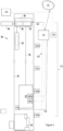
Figure 1 is a schematic view of an elevator system according to an example of the present disclosure; and -
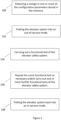
Figure 2 is a flow diagram for an exemplary method of verifying configuration parameter changes in an elevator safety system. - As shown in
Figure 1 , anelevator system 20 comprises anelevator car 22 that moves in ahoistway 34 between various floors of a building. Theelevator car 22 is suspended in thehoistway 34 by a tension member 26 (e.g. one or more ropes or belts). The other end of thetension member 26 is connected to acounterweight 24. However, it will be appreciated that in other examples the elevator system may be ropeless. - During an in-service mode, the
elevator car 22 travels up and down in thehoistway 34 to transport passengers and/or cargo between floors of the building. Theelevator car 22 is driven by adrive system 30 comprising adrive motor 32 and amotor brake 36. Thetension member 26 passes over a drive sheave (not shown) that is driven to rotate by thedrive motor 32 and slowed by themotor brake 36. Normal operation of thedrive system 30 is controlled by anelevator controller 40. Theelevator car 22 has asafety gear 28 that can be triggered to bring theelevator car 22 to an immediate standstill. Although not shown, thecounterweight 24 may also include such a safety gear. - The
elevator system 20 also comprises an absoluteposition determination system 50 configured to determine the absolute position and velocity of theelevator car 22 in thehoistway 34. In this example, the absoluteposition determination system 50 is configured to output a measurement of the absolute position and velocity of theelevator car 22 to theelevator controller 40. The absoluteposition determination system 50 can include a coded tape (not shown) extending at least part of the way along thehoistway 34 and at least one sensor (not shown) mounted on theelevator car 22 and arranged to read the coded tape to determine the absolute position and velocity of theelevator car 22 as it moves along thehoistway 34. - The
elevator system 20 also comprises anelevator safety system 53, including asafety controller 52 connected to adata bus 54. Thesafety controller 52 may be a node as defined in the relevant Programmable Electronic System in Safety Related Applications for Lifts (PESSRAL) standard(s). Thesafety controller 52 communicates over thedata bus 54 with a plurality ofsafety nodes 42a-d, 44, 46, 48a-b. Thedata bus 54 may be a CAN bus, and is represented inFigure 1 with a dashed line. - The
safety controller 52 of theelevator safety system 53 has a communicative connection with aremote computing device 70. It can be seen that theremote computing device 70 is outside theelevator system 20, and typically outside the building where theelevator system 20 is located. For example, theremote computing device 70 may be a cloud-based server (such as a building management server). Theremote computing device 70 can be used to remotely verify functional tests that are carried out during an out-of-service mode. Theremote computing device 70 can also send an instruction to theelevator safety system 53 when it is deemed appropriate to put theelevator system 20 back into an in-service mode. - The
safety nodes 42a-d, 44, 46, 48a-b are each associated with a safety sensor located in theelevator system 20. In the particular example as shown, there are foursafety nodes 42a-d for the landing doors, each corresponding to a safety sensor for the respective set of landing doors of theelevator system 20. There is asafety node 44 for the pit limit switch. There is asafety node 46 associated with a safety sensor for overspeed detection. The overspeeddetection safety node 46 is connected to the absoluteposition determination system 50. There are also shown two safety nodes, 48a, 48b, associated with safety sensors of theelevator car 22. For example, there is an elevator cardoor safety node 48a and asafety node 48b for an emergency stop switch in theelevator car 22. - In this illustrated example, the
safety controller 52 includes a memory storing configuration parameters and a processor with access to the memory. The processor is arranged to access a stored configuration parameter of relevance to an input received at aparticular safety node 42a-d, 44, 46, 48a-b and to evaluate the input with reference to the configuration parameter. Thesafety controller 52 can then output anactuation signal - The
safety controller 52 can output anactuation signal 60 to interrupt the supply of power to thedrive system 30 to execute the safety action of an emergency stop. Thisactuation signal 60 can act independently of theelevator controller 40 being configured to control thedrive system 30. Thesafety controller 52 simply allows or prevents movement of theelevator car 22, but cannot be used to move theelevator car 22 to a floor. It is theelevator controller 40 which issues a run command to thedrive system 30, whether during normal operation in the in-service mode or when carrying out a functional test during the out-of-service mode. - In another example of a safety action, the safety controller 52 (e.g. acting as an electronic speed governor) can output an
actuation signal 62 to trigger thesafety gear 28 of theelevator car 22 when the elevator car speed is input to the overspeeddetection safety node 46 and evaluated with reference to the rated speed. - In the in-service mode, an emergency stop of the
elevator car 22 may be triggered based on an input received at any of the various safety nodes connected to thesafety bus 54. For instance, if a landing door is opened (as detected by one of thesafety nodes 42a-d), if a maintenance worker operates an emergency stop switch (as detected bysafety node 48b), or theelevator car 22 travels too quickly (as detected by overspeed detection node 46), the safety action of an emergency stop may be actuated by thesafety controller 52, for example by theactuation signal 60 interrupting the supply of power to thedrive system 30. The loss of power triggers themotor brake 36 to engage and stops the motor 32 (i.e. removes any drive torque applied to the drive sheave). This brings the elevator car 22 (and the counterweight 24) quickly to a halt. However, this relies on thesafety controller 52 correctly evaluating the input with reference to the stored configuration parameters, which may change during a software update or other configuration change. - During a process of verifying configuration parameter changes in the
elevator safety system 53, theelevator controller 40 is configured to put theelevator system 20 into an out-of-service mode upon detecting any changes to the configuration parameters stored in the memory of thesafety controller 52. Then theelevator controller 40 is configured to carry out a functional test of theelevator safety system 53 by moving theempty elevator car 22 under predetermined conditions and verifying that thesafety controller 52 outputs anactuation signal elevator controller 40 or theelevator safety system 53 is then configured to put theelevator system 20 back into an in-service mode. This may be initiated automatically or upon receiving an instruction from theremote computing device 70. - There is illustrated in
Figure 2 an exemplary method of verifying configuration parameter changes in an elevator safety system, which may have the architecture seen inFigure 1 or any other suitable architecture. The steps 100-108 take place sequentially in the following temporal order. Afirst step 100 comprises detecting a change in one or more of the configuration parameters stored in the memory. Asecond step 102 comprises putting the elevator system into an out-of-service mode. Athird step 104 comprises carrying out a functional test of the elevator safety system to verify an appropriate safety action. Verification may take place automatically (e.g. by theelevator safety system 53 itself) or remotely (e.g. by the remote computing device 70). The functional test may involve moving an empty elevator car under predetermined conditions and verifying that the processor outputs an actuation signal for an appropriate safety action under these predetermined conditions. An optionalfourth step 106 is to repeat the same functional test as necessary and/or carry out one or more further functional tests of the elevator safety system. Only once there is a positive verification outcome from step 104 (and step 106 where this applies) does the process continue to thefinal step 108 which comprises putting the elevator system back into an in-service mode. - It will be appreciated by those skilled in the art that the disclosure has been illustrated by describing one or more specific examples thereof, but is not limited to these examples; many variations and modifications are possible, within the scope of the accompanying claims.
Claims (14)
- A method of verifying configuration parameter changes in an elevator safety system (53), the elevator safety system (53) comprising:
one or more safety nodes (42a-d, 44, 46, 48a-b), each arranged to monitor an input received from an associated safety sensor in an elevator system (20); a memory storing configuration parameters and a processor (52) with access to the memory; the processor (52) being arranged to access a stored configuration parameter of relevance to an input received at a safety node (42a-d, 44, 46, 48a-b) and to evaluate the input with reference to the configuration parameter; and the processor (52) being arranged to output an actuation signal (60,62) for one or more safety actions based on the evaluation of the input;
the method comprising:putting the elevator system (20) into an out-of-service mode in response to detecting a change in one or more of the configuration parameters stored in the memory;in the out-of-service mode, carrying out a functional test of the elevator safety system (53) by moving an empty elevator car (22) under predetermined conditions and verifying that the processor (52) outputs an actuation signal (60,62) for an appropriate safety action under these predetermined conditions; andthen putting the elevator system (20) back into an in-service mode. - The method of claim 1, comprising:
automatically carrying out the one or more functional tests of the elevator safety system (53) and/or automatically verifying that the processor (52) outputs an actuation signal (60,62) for an appropriate safety action. - The method of claim 1 or 2, comprising:
remotely verifying that the processor outputs an actuation signal for an appropriate safety action under these predetermined conditions. - The method of any preceding claim, comprising:
sending an instruction from a remote computing device (70) to the elevator safety system (53) to put the elevator system (20) back into an in-service mode. - The method of any preceding claim, comprising:
carrying out a plurality of functional tests of the elevator safety system (53), by moving an empty elevator car (22) in each functional test under predetermined conditions that are particular to each functional test. - The method of any preceding claim, comprising:
upon completion of the functional test(s) of the elevator safety system (53) and upon verifying that the processor (52) outputs an actuation signal (60,62) for an appropriate safety action for each functional test, automatically putting the elevator system (20) back into an in-service mode. - The method of any preceding claim, comprising:
carrying out a functional test of the elevator safety system (53) by moving an empty elevator car (22) downwards and checking that the processor (52) outputs an actuation signal for an appropriate safety action of a safety gear (28) or rope brake. - The method of any preceding claim, comprising one or more of:carrying out a functional test of the elevator safety system (53) by moving an empty elevator car (22) upwards and checking that the processor (52) outputs an actuation signal for an appropriate safety action of slowing down the elevator car when it approaches an upper terminal in a hoistway of the elevator system;carrying out a functional test of the elevator safety system (53) by moving an empty elevator car (22) upwards/downwards and checking that the processor (52) outputs an actuation signal for an appropriate safety action of stopping the elevator car when it passes a final limit in a hoistway of the elevator system;carrying out a functional test of the elevator safety system (53) by moving an empty elevator car (22) upwards and checking that the processor (52) outputs an actuation signal for an appropriate safety action relating to overspeed detection for an elevator car;carrying out a functional test of the elevator safety system (53) by moving an empty elevator car (22) upwards/downwards from a landing and checking that the processor (52) outputs an actuation signal for an appropriate safety action of preventing unintended car movement at a landing;carrying out a functional test of the elevator safety system (53) by moving an empty elevator car (22) upwards/downwards and checking that the processor (52) outputs an actuation signal for an appropriate safety action of designating an elevator car as a firefighter elevator car;carrying out a functional test of the elevator safety system (53) by moving an empty elevator car (22) upwards/downwards and checking that the processor (52) outputs an actuation signal for an appropriate safety action of locking or unlocking elevator car rear doors.
- The method of any preceding claim, comprising:
detecting a manual change in one or more of the configuration parameters stored in the memory. - The method of any preceding claim, comprising:
detecting an automatic change in one or more of the configuration parameters stored in the memory. - The method of any preceding claim, comprising:
detecting a change in one or more of the configuration parameters stored in the memory as a result of software running at the processor having been updated or replaced. - An elevator system (20) comprising:an elevator car (22) moving along a hoistway (34);an elevator controller (40), configured to control operation of the elevator car (22); andan elevator safety system (53) comprising:one or more safety nodes (42a-d, 44, 46, 48a-b), each arranged to monitor an input received from an associated safety sensor in the elevator system (20); a memory storing configuration parameters and a processor (52) with access to the memory; the processor (52) being arranged to access a stored configuration parameter of relevance to an input received at a safety node (42a-d, 44, 46, 48a-b) and to evaluate the input with reference to the configuration parameter; and the processor (52) being arranged to output an actuation signal (60,62) for one or more safety actions based on the evaluation of the input;wherein, during a process of verifying configuration parameter changes in the elevator safety system (53):the elevator controller (40) is configured to put the elevator system (20) into an out-of-service mode in response to detecting a change in one or more of the configuration parameters stored in the memory;in the out-of-service mode, the elevator controller (40) is configured to carry out a functional test of the elevator safety system (53) by moving an empty elevator car (22) under predetermined conditions and verifying that the processor (52) outputs an actuation signal (60,62) for an appropriate safety action under these predetermined conditions; andthe elevator controller (40) or the elevator safety system (53) is then configured to put the elevator system back into an in-service mode.
- The elevator system (20) of claim 12, wherein the elevator safety system (53) is arranged to verify that the processor (52) outputs an actuation signal (60,62) for an appropriate safety action.
- The elevator system (20) of claim 12 or 13, wherein the elevator safety system (53) comprises a communicative connection with a remote computing device (70) and the remote computing device (70) is arranged to:verify that the processor (52) outputs an actuation signal (60,62) for an appropriate safety action; and/orsend an instruction to the elevator safety system (53) to put the elevator system back into an in-service mode.
Priority Applications (3)
| Application Number | Priority Date | Filing Date | Title |
|---|---|---|---|
| EP22216187.9A EP4389665B1 (en) | 2022-12-22 | 2022-12-22 | Verifying configuration parameter changes in an elevator safety system |
| US18/448,251 US20240208775A1 (en) | 2022-12-22 | 2023-08-11 | Verifying configuration parameter changes in an elevator safety system |
| CN202311600176.6A CN118239348A (en) | 2022-12-22 | 2023-11-28 | Validating configuration parameter changes in elevator safety systems |
Applications Claiming Priority (1)
| Application Number | Priority Date | Filing Date | Title |
|---|---|---|---|
| EP22216187.9A EP4389665B1 (en) | 2022-12-22 | 2022-12-22 | Verifying configuration parameter changes in an elevator safety system |
Publications (2)
| Publication Number | Publication Date |
|---|---|
| EP4389665A1 true EP4389665A1 (en) | 2024-06-26 |
| EP4389665B1 EP4389665B1 (en) | 2025-07-02 |
Family
ID=84569285
Family Applications (1)
| Application Number | Title | Priority Date | Filing Date |
|---|---|---|---|
| EP22216187.9A Active EP4389665B1 (en) | 2022-12-22 | 2022-12-22 | Verifying configuration parameter changes in an elevator safety system |
Country Status (3)
| Country | Link |
|---|---|
| US (1) | US20240208775A1 (en) |
| EP (1) | EP4389665B1 (en) |
| CN (1) | CN118239348A (en) |
Citations (3)
| Publication number | Priority date | Publication date | Assignee | Title |
|---|---|---|---|---|
| US20210155455A1 (en) * | 2019-11-25 | 2021-05-27 | Otis Elevator Company | Electronic test nodes for automatic check of a safety chain |
| WO2021105192A1 (en) * | 2019-11-26 | 2021-06-03 | Alimak Group Management Ab | Brake release |
| US20220380173A1 (en) * | 2021-05-28 | 2022-12-01 | Otis Elevator Company | Elevator system and method for restoring operation of an elevator car |
-
2022
- 2022-12-22 EP EP22216187.9A patent/EP4389665B1/en active Active
-
2023
- 2023-08-11 US US18/448,251 patent/US20240208775A1/en active Pending
- 2023-11-28 CN CN202311600176.6A patent/CN118239348A/en active Pending
Patent Citations (3)
| Publication number | Priority date | Publication date | Assignee | Title |
|---|---|---|---|---|
| US20210155455A1 (en) * | 2019-11-25 | 2021-05-27 | Otis Elevator Company | Electronic test nodes for automatic check of a safety chain |
| WO2021105192A1 (en) * | 2019-11-26 | 2021-06-03 | Alimak Group Management Ab | Brake release |
| US20220380173A1 (en) * | 2021-05-28 | 2022-12-01 | Otis Elevator Company | Elevator system and method for restoring operation of an elevator car |
Also Published As
| Publication number | Publication date |
|---|---|
| US20240208775A1 (en) | 2024-06-27 |
| EP4389665B1 (en) | 2025-07-02 |
| CN118239348A (en) | 2024-06-25 |
Similar Documents
| Publication | Publication Date | Title |
|---|---|---|
| US9108823B2 (en) | Elevator safety control device | |
| US11305965B2 (en) | Elevator with safety chain overlay control unit with a safety PLC separately monitoring various safety switches for increasing a safety integrity level | |
| CN1953926B (en) | Elevator device | |
| CN103204419B (en) | Electronic safe elevator | |
| JPWO2011148411A1 (en) | Electronic safety elevator | |
| KR20110107862A (en) | Elevator device and its inspection method | |
| KR101189952B1 (en) | Elevator system | |
| CN104030102B (en) | Elevator system | |
| US20230146745A1 (en) | Avoiding entrapment in an elevator | |
| EP3533748A2 (en) | Resetting governor sub-systems | |
| US20220063955A1 (en) | Elevator systems | |
| US9580273B2 (en) | Testing apparatus and safety arrangement | |
| CN113993805B (en) | Method for testing open-door travel protection device for elevator, and open-door travel protection device for elevator | |
| EP4389665B1 (en) | Verifying configuration parameter changes in an elevator safety system | |
| EP3617116A1 (en) | Elevator door sensor fusion, fault detection, and service notification | |
| CN109689558B (en) | Car safety supervision unit and physical safety supervision unit for elevator | |
| KR102236152B1 (en) | Elevator remote monitoring system | |
| EP3878790A1 (en) | Devices, methods and computer programs for monitoring, processing and adjusting an elevator emergency stopping event | |
| JP2020079126A (en) | Elevator door control device and door control method | |
| JP7823779B1 (en) | Elevator control device and elevator control method | |
| JP7452729B1 (en) | elevator | |
| JPH08231152A (en) | Elevator control equipment | |
| KR20200113739A (en) | Remote monitoring system for elevator | |
| EP4474330A1 (en) | Elevator and method for demonstrating operation of elevator safety system | |
| KR100891234B1 (en) | Elevator device |
Legal Events
| Date | Code | Title | Description |
|---|---|---|---|
| PUAI | Public reference made under article 153(3) epc to a published international application that has entered the european phase |
Free format text: ORIGINAL CODE: 0009012 |
|
| STAA | Information on the status of an ep patent application or granted ep patent |
Free format text: STATUS: REQUEST FOR EXAMINATION WAS MADE |
|
| 17P | Request for examination filed |
Effective date: 20231003 |
|
| AK | Designated contracting states |
Kind code of ref document: A1 Designated state(s): AL AT BE BG CH CY CZ DE DK EE ES FI FR GB GR HR HU IE IS IT LI LT LU LV MC ME MK MT NL NO PL PT RO RS SE SI SK SM TR |
|
| GRAP | Despatch of communication of intention to grant a patent |
Free format text: ORIGINAL CODE: EPIDOSNIGR1 |
|
| STAA | Information on the status of an ep patent application or granted ep patent |
Free format text: STATUS: GRANT OF PATENT IS INTENDED |
|
| INTG | Intention to grant announced |
Effective date: 20250108 |
|
| GRAS | Grant fee paid |
Free format text: ORIGINAL CODE: EPIDOSNIGR3 |
|
| GRAA | (expected) grant |
Free format text: ORIGINAL CODE: 0009210 |
|
| STAA | Information on the status of an ep patent application or granted ep patent |
Free format text: STATUS: THE PATENT HAS BEEN GRANTED |
|
| AK | Designated contracting states |
Kind code of ref document: B1 Designated state(s): AL AT BE BG CH CY CZ DE DK EE ES FI FR GB GR HR HU IE IS IT LI LT LU LV MC ME MK MT NL NO PL PT RO RS SE SI SK SM TR |
|
| REG | Reference to a national code |
Ref country code: GB Ref legal event code: FG4D |
|
| REG | Reference to a national code |
Ref country code: CH Ref legal event code: EP |
|
| REG | Reference to a national code |
Ref country code: DE Ref legal event code: R096 Ref document number: 602022016833 Country of ref document: DE |
|
| REG | Reference to a national code |
Ref country code: IE Ref legal event code: FG4D |
|
| REG | Reference to a national code |
Ref country code: NL Ref legal event code: MP Effective date: 20250702 |
|
| PG25 | Lapsed in a contracting state [announced via postgrant information from national office to epo] |
Ref country code: PT Free format text: LAPSE BECAUSE OF FAILURE TO SUBMIT A TRANSLATION OF THE DESCRIPTION OR TO PAY THE FEE WITHIN THE PRESCRIBED TIME-LIMIT Effective date: 20251103 |
|
| PG25 | Lapsed in a contracting state [announced via postgrant information from national office to epo] |
Ref country code: NL Free format text: LAPSE BECAUSE OF FAILURE TO SUBMIT A TRANSLATION OF THE DESCRIPTION OR TO PAY THE FEE WITHIN THE PRESCRIBED TIME-LIMIT Effective date: 20250702 |
|
| REG | Reference to a national code |
Ref country code: AT Ref legal event code: MK05 Ref document number: 1809077 Country of ref document: AT Kind code of ref document: T Effective date: 20250702 |
|
| PG25 | Lapsed in a contracting state [announced via postgrant information from national office to epo] |
Ref country code: IS Free format text: LAPSE BECAUSE OF FAILURE TO SUBMIT A TRANSLATION OF THE DESCRIPTION OR TO PAY THE FEE WITHIN THE PRESCRIBED TIME-LIMIT Effective date: 20251102 |
|
| PG25 | Lapsed in a contracting state [announced via postgrant information from national office to epo] |
Ref country code: NO Free format text: LAPSE BECAUSE OF FAILURE TO SUBMIT A TRANSLATION OF THE DESCRIPTION OR TO PAY THE FEE WITHIN THE PRESCRIBED TIME-LIMIT Effective date: 20251002 |
|
| REG | Reference to a national code |
Ref country code: LT Ref legal event code: MG9D |
|
| PG25 | Lapsed in a contracting state [announced via postgrant information from national office to epo] |
Ref country code: AT Free format text: LAPSE BECAUSE OF FAILURE TO SUBMIT A TRANSLATION OF THE DESCRIPTION OR TO PAY THE FEE WITHIN THE PRESCRIBED TIME-LIMIT Effective date: 20250702 |
|
| PG25 | Lapsed in a contracting state [announced via postgrant information from national office to epo] |
Ref country code: FI Free format text: LAPSE BECAUSE OF FAILURE TO SUBMIT A TRANSLATION OF THE DESCRIPTION OR TO PAY THE FEE WITHIN THE PRESCRIBED TIME-LIMIT Effective date: 20250702 |
|
| PG25 | Lapsed in a contracting state [announced via postgrant information from national office to epo] |
Ref country code: HR Free format text: LAPSE BECAUSE OF FAILURE TO SUBMIT A TRANSLATION OF THE DESCRIPTION OR TO PAY THE FEE WITHIN THE PRESCRIBED TIME-LIMIT Effective date: 20250702 |
|
| PG25 | Lapsed in a contracting state [announced via postgrant information from national office to epo] |
Ref country code: GR Free format text: LAPSE BECAUSE OF FAILURE TO SUBMIT A TRANSLATION OF THE DESCRIPTION OR TO PAY THE FEE WITHIN THE PRESCRIBED TIME-LIMIT Effective date: 20251003 |
|
| PG25 | Lapsed in a contracting state [announced via postgrant information from national office to epo] |
Ref country code: CZ Free format text: LAPSE BECAUSE OF FAILURE TO SUBMIT A TRANSLATION OF THE DESCRIPTION OR TO PAY THE FEE WITHIN THE PRESCRIBED TIME-LIMIT Effective date: 20250702 Ref country code: SE Free format text: LAPSE BECAUSE OF FAILURE TO SUBMIT A TRANSLATION OF THE DESCRIPTION OR TO PAY THE FEE WITHIN THE PRESCRIBED TIME-LIMIT Effective date: 20250702 |
|
| PG25 | Lapsed in a contracting state [announced via postgrant information from national office to epo] |
Ref country code: LV Free format text: LAPSE BECAUSE OF FAILURE TO SUBMIT A TRANSLATION OF THE DESCRIPTION OR TO PAY THE FEE WITHIN THE PRESCRIBED TIME-LIMIT Effective date: 20250702 |
|
| PG25 | Lapsed in a contracting state [announced via postgrant information from national office to epo] |
Ref country code: BG Free format text: LAPSE BECAUSE OF FAILURE TO SUBMIT A TRANSLATION OF THE DESCRIPTION OR TO PAY THE FEE WITHIN THE PRESCRIBED TIME-LIMIT Effective date: 20250702 Ref country code: PL Free format text: LAPSE BECAUSE OF FAILURE TO SUBMIT A TRANSLATION OF THE DESCRIPTION OR TO PAY THE FEE WITHIN THE PRESCRIBED TIME-LIMIT Effective date: 20250702 |
|
| PG25 | Lapsed in a contracting state [announced via postgrant information from national office to epo] |
Ref country code: RS Free format text: LAPSE BECAUSE OF FAILURE TO SUBMIT A TRANSLATION OF THE DESCRIPTION OR TO PAY THE FEE WITHIN THE PRESCRIBED TIME-LIMIT Effective date: 20251002 |
|
| PG25 | Lapsed in a contracting state [announced via postgrant information from national office to epo] |
Ref country code: ES Free format text: LAPSE BECAUSE OF FAILURE TO SUBMIT A TRANSLATION OF THE DESCRIPTION OR TO PAY THE FEE WITHIN THE PRESCRIBED TIME-LIMIT Effective date: 20250702 |
|
| PG25 | Lapsed in a contracting state [announced via postgrant information from national office to epo] |
Ref country code: RO Free format text: LAPSE BECAUSE OF FAILURE TO SUBMIT A TRANSLATION OF THE DESCRIPTION OR TO PAY THE FEE WITHIN THE PRESCRIBED TIME-LIMIT Effective date: 20250702 |
|
| PG25 | Lapsed in a contracting state [announced via postgrant information from national office to epo] |
Ref country code: SM Free format text: LAPSE BECAUSE OF FAILURE TO SUBMIT A TRANSLATION OF THE DESCRIPTION OR TO PAY THE FEE WITHIN THE PRESCRIBED TIME-LIMIT Effective date: 20250702 |
|
| PG25 | Lapsed in a contracting state [announced via postgrant information from national office to epo] |
Ref country code: DK Free format text: LAPSE BECAUSE OF FAILURE TO SUBMIT A TRANSLATION OF THE DESCRIPTION OR TO PAY THE FEE WITHIN THE PRESCRIBED TIME-LIMIT Effective date: 20250702 |
|
| PGFP | Annual fee paid to national office [announced via postgrant information from national office to epo] |
Ref country code: DE Payment date: 20260319 Year of fee payment: 4 |
|
| PG25 | Lapsed in a contracting state [announced via postgrant information from national office to epo] |
Ref country code: IT Free format text: LAPSE BECAUSE OF FAILURE TO SUBMIT A TRANSLATION OF THE DESCRIPTION OR TO PAY THE FEE WITHIN THE PRESCRIBED TIME-LIMIT Effective date: 20250702 |
|
| PGFP | Annual fee paid to national office [announced via postgrant information from national office to epo] |
Ref country code: FR Payment date: 20260319 Year of fee payment: 4 |
|
| PG25 | Lapsed in a contracting state [announced via postgrant information from national office to epo] |
Ref country code: SK Free format text: LAPSE BECAUSE OF FAILURE TO SUBMIT A TRANSLATION OF THE DESCRIPTION OR TO PAY THE FEE WITHIN THE PRESCRIBED TIME-LIMIT Effective date: 20250702 Ref country code: EE Free format text: LAPSE BECAUSE OF FAILURE TO SUBMIT A TRANSLATION OF THE DESCRIPTION OR TO PAY THE FEE WITHIN THE PRESCRIBED TIME-LIMIT Effective date: 20250702 |
|
| PLBE | No opposition filed within time limit |
Free format text: ORIGINAL CODE: 0009261 |
|
| STAA | Information on the status of an ep patent application or granted ep patent |
Free format text: STATUS: NO OPPOSITION FILED WITHIN TIME LIMIT |