EP4389609A1 - Mobile object and battery unit - Google Patents
Mobile object and battery unit Download PDFInfo
- Publication number
- EP4389609A1 EP4389609A1 EP23215723.0A EP23215723A EP4389609A1 EP 4389609 A1 EP4389609 A1 EP 4389609A1 EP 23215723 A EP23215723 A EP 23215723A EP 4389609 A1 EP4389609 A1 EP 4389609A1
- Authority
- EP
- European Patent Office
- Prior art keywords
- coolant
- battery
- liquefied
- mobile object
- uav
- Prior art date
- Legal status (The legal status is an assumption and is not a legal conclusion. Google has not performed a legal analysis and makes no representation as to the accuracy of the status listed.)
- Pending
Links
Images


Classifications
-
- B—PERFORMING OPERATIONS; TRANSPORTING
- B64—AIRCRAFT; AVIATION; COSMONAUTICS
- B64U—UNMANNED AERIAL VEHICLES [UAV]; EQUIPMENT THEREFOR
- B64U20/00—Constructional aspects of UAVs
- B64U20/90—Cooling
- B64U20/98—Cooling using liquid, e.g. using lubrication oil
-
- B—PERFORMING OPERATIONS; TRANSPORTING
- B64—AIRCRAFT; AVIATION; COSMONAUTICS
- B64D—EQUIPMENT FOR FITTING IN OR TO AIRCRAFT; FLIGHT SUITS; PARACHUTES; ARRANGEMENT OR MOUNTING OF POWER PLANTS OR PROPULSION TRANSMISSIONS IN AIRCRAFT
- B64D27/00—Arrangement or mounting of power plants in aircraft; Aircraft characterised by the type or position of power plants
- B64D27/02—Aircraft characterised by the type or position of power plants
- B64D27/30—Aircraft characterised by electric power plants
- B64D27/35—Arrangements for on-board electric energy production, distribution, recovery or storage
- B64D27/357—Arrangements for on-board electric energy production, distribution, recovery or storage using batteries
-
- H—ELECTRICITY
- H01—ELECTRIC ELEMENTS
- H01M—PROCESSES OR MEANS, e.g. BATTERIES, FOR THE DIRECT CONVERSION OF CHEMICAL ENERGY INTO ELECTRICAL ENERGY
- H01M10/00—Secondary cells; Manufacture thereof
- H01M10/60—Heating or cooling; Temperature control
- H01M10/61—Types of temperature control
- H01M10/613—Cooling or keeping cold
-
- B—PERFORMING OPERATIONS; TRANSPORTING
- B60—VEHICLES IN GENERAL
- B60L—PROPULSION OF ELECTRICALLY-PROPELLED VEHICLES; SUPPLYING ELECTRIC POWER FOR AUXILIARY EQUIPMENT OF ELECTRICALLY-PROPELLED VEHICLES; ELECTRODYNAMIC BRAKE SYSTEMS FOR VEHICLES IN GENERAL; MAGNETIC SUSPENSION OR LEVITATION FOR VEHICLES; MONITORING OPERATING VARIABLES OF ELECTRICALLY-PROPELLED VEHICLES; ELECTRIC SAFETY DEVICES FOR ELECTRICALLY-PROPELLED VEHICLES
- B60L50/00—Electric propulsion with power supplied within the vehicle
- B60L50/50—Electric propulsion with power supplied within the vehicle using propulsion power supplied by batteries or fuel cells
- B60L50/60—Electric propulsion with power supplied within the vehicle using propulsion power supplied by batteries or fuel cells using power supplied by batteries
- B60L50/64—Constructional details of batteries specially adapted for electric vehicles
-
- B—PERFORMING OPERATIONS; TRANSPORTING
- B60—VEHICLES IN GENERAL
- B60L—PROPULSION OF ELECTRICALLY-PROPELLED VEHICLES; SUPPLYING ELECTRIC POWER FOR AUXILIARY EQUIPMENT OF ELECTRICALLY-PROPELLED VEHICLES; ELECTRODYNAMIC BRAKE SYSTEMS FOR VEHICLES IN GENERAL; MAGNETIC SUSPENSION OR LEVITATION FOR VEHICLES; MONITORING OPERATING VARIABLES OF ELECTRICALLY-PROPELLED VEHICLES; ELECTRIC SAFETY DEVICES FOR ELECTRICALLY-PROPELLED VEHICLES
- B60L58/00—Methods or circuit arrangements for monitoring or controlling batteries or fuel cells, specially adapted for electric vehicles
- B60L58/10—Methods or circuit arrangements for monitoring or controlling batteries or fuel cells, specially adapted for electric vehicles for monitoring or controlling batteries
- B60L58/24—Methods or circuit arrangements for monitoring or controlling batteries or fuel cells, specially adapted for electric vehicles for monitoring or controlling batteries for controlling the temperature of batteries
- B60L58/26—Methods or circuit arrangements for monitoring or controlling batteries or fuel cells, specially adapted for electric vehicles for monitoring or controlling batteries for controlling the temperature of batteries by cooling
-
- B—PERFORMING OPERATIONS; TRANSPORTING
- B64—AIRCRAFT; AVIATION; COSMONAUTICS
- B64D—EQUIPMENT FOR FITTING IN OR TO AIRCRAFT; FLIGHT SUITS; PARACHUTES; ARRANGEMENT OR MOUNTING OF POWER PLANTS OR PROPULSION TRANSMISSIONS IN AIRCRAFT
- B64D33/00—Arrangement in aircraft of power plant parts or auxiliaries not otherwise provided for
- B64D33/08—Arrangement in aircraft of power plant parts or auxiliaries not otherwise provided for of power plant cooling systems
-
- B—PERFORMING OPERATIONS; TRANSPORTING
- B64—AIRCRAFT; AVIATION; COSMONAUTICS
- B64U—UNMANNED AERIAL VEHICLES [UAV]; EQUIPMENT THEREFOR
- B64U10/00—Type of UAV
- B64U10/10—Rotorcrafts
- B64U10/13—Flying platforms
- B64U10/14—Flying platforms with four distinct rotor axes, e.g. quadcopters
-
- B—PERFORMING OPERATIONS; TRANSPORTING
- B64—AIRCRAFT; AVIATION; COSMONAUTICS
- B64U—UNMANNED AERIAL VEHICLES [UAV]; EQUIPMENT THEREFOR
- B64U20/00—Constructional aspects of UAVs
- B64U20/90—Cooling
-
- B—PERFORMING OPERATIONS; TRANSPORTING
- B64—AIRCRAFT; AVIATION; COSMONAUTICS
- B64U—UNMANNED AERIAL VEHICLES [UAV]; EQUIPMENT THEREFOR
- B64U50/00—Propulsion; Power supply
- B64U50/30—Supply or distribution of electrical power
-
- H—ELECTRICITY
- H01—ELECTRIC ELEMENTS
- H01M—PROCESSES OR MEANS, e.g. BATTERIES, FOR THE DIRECT CONVERSION OF CHEMICAL ENERGY INTO ELECTRICAL ENERGY
- H01M10/00—Secondary cells; Manufacture thereof
- H01M10/60—Heating or cooling; Temperature control
- H01M10/62—Heating or cooling; Temperature control specially adapted for specific applications
- H01M10/625—Vehicles
-
- H—ELECTRICITY
- H01—ELECTRIC ELEMENTS
- H01M—PROCESSES OR MEANS, e.g. BATTERIES, FOR THE DIRECT CONVERSION OF CHEMICAL ENERGY INTO ELECTRICAL ENERGY
- H01M10/00—Secondary cells; Manufacture thereof
- H01M10/60—Heating or cooling; Temperature control
- H01M10/65—Means for temperature control structurally associated with the cells
- H01M10/655—Solid structures for heat exchange or heat conduction
- H01M10/6556—Solid parts with flow channel passages or pipes for heat exchange
-
- H—ELECTRICITY
- H01—ELECTRIC ELEMENTS
- H01M—PROCESSES OR MEANS, e.g. BATTERIES, FOR THE DIRECT CONVERSION OF CHEMICAL ENERGY INTO ELECTRICAL ENERGY
- H01M10/00—Secondary cells; Manufacture thereof
- H01M10/60—Heating or cooling; Temperature control
- H01M10/65—Means for temperature control structurally associated with the cells
- H01M10/656—Means for temperature control structurally associated with the cells characterised by the type of heat-exchange fluid
- H01M10/6567—Liquids
- H01M10/6568—Liquids characterised by flow circuits, e.g. loops, located externally to the cells or cell casings
-
- H—ELECTRICITY
- H01—ELECTRIC ELEMENTS
- H01M—PROCESSES OR MEANS, e.g. BATTERIES, FOR THE DIRECT CONVERSION OF CHEMICAL ENERGY INTO ELECTRICAL ENERGY
- H01M10/00—Secondary cells; Manufacture thereof
- H01M10/60—Heating or cooling; Temperature control
- H01M10/65—Means for temperature control structurally associated with the cells
- H01M10/656—Means for temperature control structurally associated with the cells characterised by the type of heat-exchange fluid
- H01M10/6569—Fluids undergoing a liquid-gas phase change or transition, e.g. evaporation or condensation
-
- H—ELECTRICITY
- H01—ELECTRIC ELEMENTS
- H01M—PROCESSES OR MEANS, e.g. BATTERIES, FOR THE DIRECT CONVERSION OF CHEMICAL ENERGY INTO ELECTRICAL ENERGY
- H01M10/00—Secondary cells; Manufacture thereof
- H01M10/60—Heating or cooling; Temperature control
- H01M10/65—Means for temperature control structurally associated with the cells
- H01M10/659—Means for temperature control structurally associated with the cells by heat storage or buffering, e.g. heat capacity or liquid-solid phase changes or transition
-
- H—ELECTRICITY
- H01—ELECTRIC ELEMENTS
- H01M—PROCESSES OR MEANS, e.g. BATTERIES, FOR THE DIRECT CONVERSION OF CHEMICAL ENERGY INTO ELECTRICAL ENERGY
- H01M50/00—Constructional details or processes of manufacture of the non-active parts of electrochemical cells other than fuel cells, e.g. hybrid cells
- H01M50/20—Mountings; Secondary casings or frames; Racks, modules or packs; Suspension devices; Shock absorbers; Transport or carrying devices; Holders
- H01M50/249—Mountings; Secondary casings or frames; Racks, modules or packs; Suspension devices; Shock absorbers; Transport or carrying devices; Holders specially adapted for aircraft or vehicles, e.g. cars or trains
-
- H—ELECTRICITY
- H01—ELECTRIC ELEMENTS
- H01M—PROCESSES OR MEANS, e.g. BATTERIES, FOR THE DIRECT CONVERSION OF CHEMICAL ENERGY INTO ELECTRICAL ENERGY
- H01M50/00—Constructional details or processes of manufacture of the non-active parts of electrochemical cells other than fuel cells, e.g. hybrid cells
- H01M50/60—Arrangements or processes for filling or topping-up with liquids; Arrangements or processes for draining liquids from casings
- H01M50/691—Arrangements or processes for draining liquids from casings; Cleaning battery or cell casings
-
- B—PERFORMING OPERATIONS; TRANSPORTING
- B60—VEHICLES IN GENERAL
- B60L—PROPULSION OF ELECTRICALLY-PROPELLED VEHICLES; SUPPLYING ELECTRIC POWER FOR AUXILIARY EQUIPMENT OF ELECTRICALLY-PROPELLED VEHICLES; ELECTRODYNAMIC BRAKE SYSTEMS FOR VEHICLES IN GENERAL; MAGNETIC SUSPENSION OR LEVITATION FOR VEHICLES; MONITORING OPERATING VARIABLES OF ELECTRICALLY-PROPELLED VEHICLES; ELECTRIC SAFETY DEVICES FOR ELECTRICALLY-PROPELLED VEHICLES
- B60L2200/00—Type of vehicles
- B60L2200/10—Air crafts
-
- B—PERFORMING OPERATIONS; TRANSPORTING
- B60—VEHICLES IN GENERAL
- B60L—PROPULSION OF ELECTRICALLY-PROPELLED VEHICLES; SUPPLYING ELECTRIC POWER FOR AUXILIARY EQUIPMENT OF ELECTRICALLY-PROPELLED VEHICLES; ELECTRODYNAMIC BRAKE SYSTEMS FOR VEHICLES IN GENERAL; MAGNETIC SUSPENSION OR LEVITATION FOR VEHICLES; MONITORING OPERATING VARIABLES OF ELECTRICALLY-PROPELLED VEHICLES; ELECTRIC SAFETY DEVICES FOR ELECTRICALLY-PROPELLED VEHICLES
- B60L2240/00—Control parameters of input or output; Target parameters
- B60L2240/60—Navigation input
- B60L2240/62—Vehicle position
- B60L2240/622—Vehicle position by satellite navigation
-
- B—PERFORMING OPERATIONS; TRANSPORTING
- B64—AIRCRAFT; AVIATION; COSMONAUTICS
- B64U—UNMANNED AERIAL VEHICLES [UAV]; EQUIPMENT THEREFOR
- B64U2101/00—UAVs specially adapted for particular uses or applications
- B64U2101/45—UAVs specially adapted for particular uses or applications for releasing liquids or powders in-flight, e.g. crop-dusting
-
- H—ELECTRICITY
- H01—ELECTRIC ELEMENTS
- H01M—PROCESSES OR MEANS, e.g. BATTERIES, FOR THE DIRECT CONVERSION OF CHEMICAL ENERGY INTO ELECTRICAL ENERGY
- H01M2220/00—Batteries for particular applications
- H01M2220/20—Batteries in motive systems, e.g. vehicle, ship, plane
-
- Y—GENERAL TAGGING OF NEW TECHNOLOGICAL DEVELOPMENTS; GENERAL TAGGING OF CROSS-SECTIONAL TECHNOLOGIES SPANNING OVER SEVERAL SECTIONS OF THE IPC; TECHNICAL SUBJECTS COVERED BY FORMER USPC CROSS-REFERENCE ART COLLECTIONS [XRACs] AND DIGESTS
- Y02—TECHNOLOGIES OR APPLICATIONS FOR MITIGATION OR ADAPTATION AGAINST CLIMATE CHANGE
- Y02E—REDUCTION OF GREENHOUSE GAS [GHG] EMISSIONS, RELATED TO ENERGY GENERATION, TRANSMISSION OR DISTRIBUTION
- Y02E60/00—Enabling technologies; Technologies with a potential or indirect contribution to GHG emissions mitigation
- Y02E60/10—Energy storage using batteries
Definitions
- the invention relates to a mobile object and a battery unit.
- Batteries are typically used as a source of energy for driving mobile objects, such as multicopters. Such a battery becomes hot due to heat generated in the process of releasing energy. With this in view, the battery is equipped with a cooling system.
- the cooling system include an air cooling system configured to cool a battery by using a cooling fan and a refrigerant cooling system configured to cool a battery by using a pump to circulate refrigerant cooled by a cooling device such as a radiator.
- Such a cooling system consumes energy to operate a cooling device, such as a cooling fan or a pump. Installation of the cooling device leads to an increase in the weight of the body of the mobile object such that the mobile object consumes more energy in flight.
- Japanese Unexamined Patent Application Publication JP 2012- 248 363 A describes a technique for cooling battery cells in an apparatus without the use of a cooling device.
- the technique involves the use of a cool storage medium (refrigerant pack) that is placed in close proximity to the battery cells.
- the cool storage medium is able to be in close contact with battery cells to cool the battery cells.
- An aspect of the invention provides a mobile object including a battery, a coolant, and a discharger.
- the coolant in a solid state is disposed around the battery and is configured to be liquefied by heat transferred from the battery.
- the discharger is configured to discharge the coolant liquefied out of the mobile object.
- An aspect of the invention provides a battery unit including a battery, a coolant in a solid state, and an accommodation member.
- the coolant in a solid state is disposed around the battery.
- the battery and the coolant are accommodated in the accommodation member.
- the battery, the coolant, and the accommodation member are combined in one module.
- the cool storage medium is left unremoved in the apparatus after running out of cooling capacity. Discharging the coolant that has run out of cooling capacity realizes further weight reduction of the apparatus.
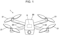
- FIG. 1 is a perspective view of an unmanned aerial vehicle 1 according to the embodiment
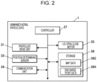
- FIG. 2 is a block diagram schematically illustrating the control configuration of the unmanned aerial vehicle 1 according to the embodiment.
- the unmanned aerial vehicle (UAV) 1 is an example of a mobile object according to an embodiment of the invention.
- the UAV 1 is a multicopter with rotor blades (propeller) 21 that provide thrust to obtain lift.
- the UAV 1 is designed to perform autonomous flight in accordance with a flight program written in advance. In some embodiments, however, the UAV 1 is controlled in accordance with a flight control signal transmitted from a remote location.
- the UAV 1 includes a main body 20 and the rotor blades 21.
- the main body 20 is box-shaped (a rectangular parallelepiped) and houses a battery unit 5, which provides power to modules constituting the UAV 1.
- the rotor blades 21 are provided to tips of four arms 22, which extend from the main body 20 in respective directions.
- the UAV 1 includes a propeller drive unit 31, a position-determining sensor 33, a communication unit 34, a lid open-close motor 35, a storage 36, and a controller 37.
- the propeller drive unit 31 includes motors and electromagnetic brakes (not illustrated) that are provided for the respective rotor blades 21. In accordance with a control signal from the controller 37, the propeller drive unit 31 drives (rotates) the rotor blades 21 and applies brakes to the rotor blades 21.
- the position-determining sensor 33 is, for example, a Global Navigation Satellite System (GNSS) receiver.
- GNSS Global Navigation Satellite System
- the position-determining sensor 33 determines the present position (including altitude) of the UAV 1 and outputs the result to the controller 37.
- GNSS Global Navigation Satellite System
- the communication unit 34 is a communication device capable of transmitting and receiving various kinds of information through a communication network.
- the communication unit 34 and a flight control device in a remote location exchange various kinds of information with each other.
- the lid open-close motor 35 enables a discharge lid 523 of the battery unit 5, which will be described later, to be opened and closed.
- the lid open-close motor 35 opens and closes the discharge lid 523 in accordance with a control signal from the controller 37.
- the storage 36 is memory, such as random-access memory (RAM) or read-only memory (ROM). Various kinds of programs and data are stored in the storage 36, which also serves as a work area for the controller 37. In the embodiment, map data 362 and discharge point data 364 are stored in the storage 36.
- RAM random-access memory
- ROM read-only memory
- the map data 362 is map information at least including the information about the (planned) flight area of the UAV 1.
- the map data 362 may include topographic information (e.g., information concerning mountains and rivers) and geographic information concerning land use (e.g., roads, railroads, architectural structures, and cultivated fields).
- the discharge point data 364 is data (positional information) about potential discharge areas where a coolant 54 can be discharged.
- the coolant 54 in the embodiment is water and will be described later.
- the potential discharge areas in the embodiment refer to regions where the coolant 54 can be discharged midair with a negligible adverse effect on the environment. Examples of the potential discharge areas include lakes, marshes, and the sea.
- the discharge point data 364 may be any kind of information that can be used to locate the potential discharge areas.
- the discharge point data 364 may be stored in association with the map data 362 or may be stored as part of the map data 362.
- Programs for carrying out a drainage procedure are stored in advance in the storage 36 in the embodiment.
- the drainage procedure will be described later.
- the controller 37 in one example is a central processing unit (CPU) and is configured to control the operation of the modules constituting the UAV 1. For example, the controller 37 retrieves a program stored in advance in the storage 36 and runs the program to execute various kinds of processing.
- CPU central processing unit
- FIG. 3A is a perspective view of the battery unit 5, and FIG. 3B is a sectional view of the battery unit 5 taken along line IIIB-IIIB in FIG. 3A .
- the coolant 54 which will be described later, is not illustrated in FIG. 3A .
- a battery main body is not illustrated in FIG. 3B .
- the battery unit 5 includes a battery (battery main body) 51 and a case 52.
- the battery 51 supplies power to the modules (e.g., the propeller drive unit 31 and the controller 37) and is accommodated in the case 52.
- the battery 51 includes a battery housing 510 and a front panel 512.
- the battery housing 510 is substantially a rectangular parallelepiped elongated in the front-and-rear direction than in the other directions.
- the front surface of the battery housing 510 is covered with the front panel 512.
- Feeder cables 513 are coupled to the front panel 512.
- the battery housing 510 and the front panel 512 are members having high thermal conductivity and are made of, for example, metal.
- the inner part of the battery 51 is hermetically sealed by the battery housing 510 and the front panel 512.
- the coolant 54 which will be described later, is a material that does not cause current leakage from the battery 51, when liquefied.
- the inner part of the battery 51 is not necessarily hermetically sealed by the battery housing 510 and the front panel 512.
- the case 52 is, for example, box-shaped (a rectangular parallelepiped) and has an opening in its front.
- the opening in the front of the case 52 can be sealed liquid-tight with a lid member 53 so that at least liquid leakage can be prevented.
- the lid member 53 is detachable or rotatable.
- the case 52 includes a heat insulating material to stop heat from going into or out of the case 52.
- an insulating material is not integrated into the case 2 as long as the case 52 and an insulating material are capable of suitably suppressing heat transfer into or out of the case 52.
- the insulating material may be disposed separately on an inner surface or an outer surface of the case 52.
- the battery 51 is supported by legs 521, which are disposed to stand on a lower surface inside the case 52.
- the legs 521 are aligned in two rows to support the right end and the left end of the battery 51, with a predetermined amount of space between the two rows on the right and left sides.
- the legs 521 in each of the right and left rows are aligned with a space therebetween in the front-and-rear direction.
- the lower surface inside the case 52 has a cavity 522, which is funnel-shaped.
- the cavity 522 is composed of a conical cavity 522a and a cylindrical cavity 522b.
- the conical cavity 522a is located on the upper side and tapers downward.
- the cylindrical cavity 522b extends downward from a lower end of the conical cavity 522a.
- the conical cavity 522a is located substantially in the middle of the lower surface of the case 52 and between the row of the legs 521 on the right and the row of the legs 521 on the left such that an opening is defined below the battery 51 disposed on the legs 521.
- the opening at the lower end of the cylindrical cavity 522b leads to the outside (underside) of the UAV 1 and can be closed with the discharge lid 523.
- the cylindrical cavity 522b is by default closed with the discharge lid 523.
- the lid open-close motor 35 (see FIG. 2 ) can expose the cylindrical cavity 522b by opening the discharge lid 523.
- the battery 51 is disposed on and fastened to the legs 521 within the case 52. Accordingly, the battery 51 is placed in the case 52 at the center between the right side and the left side of the case 52. That is, the case 52 defines a space S around the battery 51, and the battery 51 is accommodated in the case 52.
- the coolant 54 is disposed in the space S defined around the battery 51 within the case 52.
- the space S in the case 52 is filled with the coolant 54 such that the right side, the left side, and the upper side of the battery 51 are covered with the coolant 54.
- the coolant 54 is inverted U-shaped when viewed from the front.
- the coolant 54 in the embodiment is ice (solid) that becomes water (liquid) by absorbing heat from the battery 51 during operation.
- the coolant 54 has a notably high latent heat capacity with respect to the battery 51 and therefore enables a change of state to occur.
- the coolant 54 may be any material (substance) that can facilitate heat removal from the battery 51 through a change of state (solid to liquid).
- the coolant 54 may be a liquid containing an additive that improves, for example, cooling efficiency.
- the liquid may be passed through a filter to recover the additive when being discharged.
- the coolant 54 is a substance that places a negligible load on the environment.
- the coolant 54 in the space S is not limited to a solid of a particular shape, and the number of coolants used as the coolant 54 in the space S is not limited. For example, a large number of coolants 54 may be packed into the space S.
- the coolant 54 in a solid state be close to the battery 51 so that heat of the battery 51 can be transferred to the coolant 54.
- the coolant 54 in a solid state is disposed at least on the upper side of the battery 51.
- the battery unit 5 is in the form of a cassette (cartridge) and can be removed from the main body of the UAV 1. That is, the battery 51, the case 52, and the coolant 54 in a solid state (or further the lid member 53) are combined in one module (unit), which is herein referred to as the battery unit 5.
- the battery 51, the case 52, and the coolant 54 in a solid state, as a single entity, can be attached to and detached from the main body of the UAV 1. As will be described later, all or part of the coolant 54 is liquefied and discharged by the time the battery unit 5 including the battery 51 after use is removed from the main body.
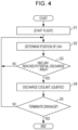
- FIG. 4 is a flowchart of a drainage procedure.
- Drainage is the process by which the coolant 54 liquefied is discharged out of the UAV 1 in flight.
- the controller 37 starts the drainage procedure by retrieving a relevant program from the storage 36 and running the program.
- the coolant 54 in a solid state and the coolant 54 liquefied may be hereinafter denoted by 54S and 54L respectively, to be distinguished from each other.
- the UAV 1 under the control of the controller 37 begins flying autonomously in accordance with a predetermined flight program (Step S1).
- the UAV 1 begins flying autonomously along a predetermined route to reach its destination.
- the drainage procedure may be incorporated into the flight program.
- the controller 37 acquires information about the present position of the UAV 1 (Step S2).
- the controller 37 causes the position-determining sensor 33 to determine the position of the UAV 1.
- the controller 37 determines whether the UAV 1 has reached a potential discharge area where the coolant 54 liquefied can be discharged (Step S3).
- the controller 37 determines that the UAV 1 has reached a potential discharge area.
- Step S3 When the controller 37 determines that the UAV 1 has yet to reach any potential discharge area (NO in Step S3), a return to Step S2 is made.
- Steps S2 and S3 may be performed without the use of the positional information obtained by the position-determining sensor 33. That is, any other methods may be adopted as long as whether the UAV 1 has reached a potential discharge area is determined. For example, such steps may involve the use of image information obtained by an imaging apparatus or may involve the use of azimuth information obtained by an azimuth sensor and/or distance information obtained by a distance sensor.
- Step S3 When determining in Step S3 that the UAV 1 has reached a potential discharge area (YES in Step S3), the controller 37 causes the drainage to occur such that the coolant 54L liquefied is discharged from the battery unit 5 (Step S4).
- the lid open-close motor 35 is driven by the controller 37 and opens the discharge lid 523 to enable the drainage to occur.
- the lower end of the cylindrical cavity 522b which is part of the cavity 522 and has been closed with the discharge lid 523, is opened to enable the coolant 54L retained in the case 52 to be discharged out of the UAV 1 through the cavity 522. After being discharged, the coolant 54L falls to the ground in the potential discharge area.
- the controller 37 determines whether it is time to terminate the drainage procedure (Step S5). When it is not time to terminate the drainage procedure (NO in Step S5), a return to Step S2 is made.
- Step S5 When it is time to terminate the drainage procedure (e.g., when the UAV 1 arrives at the destination) (YES in Step S5), the controller 37 terminates the drainage procedure.
- a cooling apparatus e.g., a cooling fan or a radiator
- energy electric power
- the coolant 54 When running out of cooling capacity, the coolant 54 liquefies. The coolant 54 liquefied is then discharged. As a result, the weight of the body (the battery unit 5) is reduced while the UAV 1 is flying.
- the weight reduction and the suitable cooling of the battery 51 can be achieved at the same time.
- the coolant 54L liquefied is discharged.
- the coolant 54 can be discharged safely and without any significant environmental impact caused by discharging the coolant 54L liquefied.
- the case 52 in which the battery 51 and the coolant 54 are accommodated, includes an insulating material disposed around the coolant 54.
- the coolant 54 in turn can provide suitable cooling of the battery 51.
- the battery 51, the coolant 54 in a solid state disposed around the battery 51, and the case 52 in which the battery 51 and the coolant 54 are accommodated are combined in one module.
- the battery 51, the coolant 54, and the case 52 can thus be attached to and detached from the main body of the UAV 1. That is, the battery unit 5 including the battery 51 in a charged state and packed with the coolant 54 can be easily installed in the main body of the UAV 1. This provides ease of replacing or recharging the battery 51 and replenishing the coolant 54.
- the lower end of the cavity 522 of the case 52 is opened to let the coolant 54L fall, thereby discharging the coolant 54L liquefied to the outside.
- Modifications 1 to 3 which will be described below, are adopted so that the coolant 54L will not fall to the ground as it is.
- Modifications 1 to 3 may be adopted when the coolant 54L is to be discharged in large amounts.
- a fibrous member 55 in the form of cloth may be coupled to the lower end of the cavity 522 (the cylindrical cavity 522b).
- the fibrous member 55 on the UAV 1 is exposed to the outside.
- the coolant 54L liquefied flows through the cylindrical cavity 522b and is then absorbed by the fibrous member 55.
- the coolant 54L absorbed by the fibrous member 55 is vaporized upon contact with the airstream around the UAV 1 in flight. This speeds up the process of volatilization of the coolant 54L liquefied and eliminates or reduces the possibility that the coolant 54L will fall to the ground as it is.
- the fibrous member 55 may be made of any material that can absorb the coolant 54L liquefied, and the fibrous member 55 may have any form that helps promote the vaporization of the coolant 54L in contact with the airstream.
- the fibrous member 55 may be extendable and retractable, and when appropriate, the fibrous member 55 extends out from the body of the UAV 1 so that the coolant 54L can be vaporized.
- the discharge lid 523 at the lower end of the cylindrical cavity 522b is optional.
- the coolant 54L liquefied may be discharged toward one of the rotor blades 21 such that the coolant 54L is diffused by the airstream generated by the rotor blade 21.
- the tip of the cylindrical cavity 522b (and a pipe leading thereto) is oriented toward any one of the rotor blades 21, with an opening provided in close proximity to the rotor blade 21. While being diffused by the rotor blade 21, the coolant 54L in a fine spray is emitted into the atmosphere. This eliminates or reduces the possibility that the coolant 54L will fall to the ground as it is.
- the discharge lid 523 at the lower end of the cylindrical cavity 522b is optional.
- the coolant 54L liquefied may be collected in a pan (drip tray) 56 and then vaporized (evaporated) by a heating element 561.
- the pan 56 is disposed at the lower end of the cavity 522 (the cylindrical cavity 522b).
- the heating element 561 is, for example, a heating wire and is disposed in the bottom of the pan 56.
- the heating element 561 disposed as above vaporizes the coolant 54L collected in the pan 56. This eliminates or reduces the possibility that the coolant 54L will fall to the ground as it is.
- the discharge lid 523 at the lower end of the cylindrical cavity 522b is optional.
- the battery unit 5 (the battery 51, the coolant 54, and the case 52) in the embodiment described above are combined in one module, which is herein referred to as the battery unit 5.
- the battery 51, the coolant 54, and the case 52 are not combined in one module (unit).
- the coolant 54 when the coolant 54 is replenished, for example, the coolant 54 alone can be put into the case 52 by opening the lid member 53 in the front of the case 52.
- the coolant 54L liquefied is discharged in the potential discharge area or vaporized.
- the coolant 54 is a substance that places a negligible load on the environment, the coolant 54L liquefied may be discharged at any place as it is irrespective of its state.
- the mobile object may be an aircraft (a manned aircraft) operated by an occupant (pilot).
- the invention is widely applicable, in addition to aircrafts, to other mobile objects equipped with batteries.
- mobile objects include vehicles, watercraft, and toys thereof.
- a coolant used for cooling of a battery and liquefied is then discharged from a discharger to the outside. This provides suitable battery cooling and weight reduction.
Landscapes
- Engineering & Computer Science (AREA)
- Chemical & Material Sciences (AREA)
- Chemical Kinetics & Catalysis (AREA)
- Electrochemistry (AREA)
- General Chemical & Material Sciences (AREA)
- Mechanical Engineering (AREA)
- Manufacturing & Machinery (AREA)
- Aviation & Aerospace Engineering (AREA)
- Remote Sensing (AREA)
- Life Sciences & Earth Sciences (AREA)
- Sustainable Development (AREA)
- Sustainable Energy (AREA)
- Power Engineering (AREA)
- Transportation (AREA)
- Combustion & Propulsion (AREA)
- Oil, Petroleum & Natural Gas (AREA)
- Secondary Cells (AREA)
Abstract
Description
- The invention relates to a mobile object and a battery unit.
- Batteries are typically used as a source of energy for driving mobile objects, such as multicopters. Such a battery becomes hot due to heat generated in the process of releasing energy. With this in view, the battery is equipped with a cooling system. Common examples of the cooling system include an air cooling system configured to cool a battery by using a cooling fan and a refrigerant cooling system configured to cool a battery by using a pump to circulate refrigerant cooled by a cooling device such as a radiator.
- Such a cooling system consumes energy to operate a cooling device, such as a cooling fan or a pump. Installation of the cooling device leads to an increase in the weight of the body of the mobile object such that the mobile object consumes more energy in flight.
- Japanese Unexamined Patent Application Publication
JP 2012- 248 363 A - An aspect of the invention provides a mobile object including a battery, a coolant, and a discharger. The coolant in a solid state is disposed around the battery and is configured to be liquefied by heat transferred from the battery. The discharger is configured to discharge the coolant liquefied out of the mobile object.
- An aspect of the invention provides a battery unit including a battery, a coolant in a solid state, and an accommodation member. The coolant in a solid state is disposed around the battery. The battery and the coolant are accommodated in the accommodation member. The battery, the coolant, and the accommodation member are combined in one module.
- The accompanying drawings are included to provide a further understanding of the invention and are incorporated in and constitute a part of this specification. The drawings illustrate embodiments and, together with the specification, serve to describe the principles of the invention.
-
FIG. 1 is a perspective view of an unmanned aerial vehicle according to an embodiment; -
FIG. 2 is a block diagram schematically illustrating the control configuration of the unmanned aerial vehicle according to the embodiment; -
FIG. 3A is a perspective view of a battery unit according to the embodiment; -
FIG. 3B is a sectional view of the battery unit taken along line IIIB-IIIB inFIG. 3A ; -
FIG. 4 is a flowchart of a drainage procedure according to the embodiment; -
FIG. 5 schematically illustratesModification 1 of the unmanned aerial vehicle according to the embodiment; -
FIG. 6 schematically illustrates Modification 2 of the unmanned aerial vehicle according to the embodiment; and -
FIG. 7 schematically illustrates Modification 3 of the unmanned aerial vehicle according to the embodiment. - According to the technique described in
JP 2012- 248 363 A - It is desirable to provide suitable battery cooling and weight reduction.
- In the following, an embodiment of the invention is described in detail with reference to the accompanying drawings. Note that the following description is directed to an illustrative example of the invention and not to be construed as limiting to the invention. Factors including, without limitation, numerical values, shapes, materials, components, positions of the components, and how the components are coupled to each other are illustrative only and not to be construed as limiting to the invention.
- Further, elements in the following example embodiment which are not recited in a most-generic independent claim of the invention are optional and may be provided on an as-needed basis. The drawings are schematic and are not intended to be drawn to scale. Throughout the present specification and the drawings, elements having substantially the same function and configuration are denoted with the same numerals to avoid any redundant description. Overall Configuration of Unmanned Aerial Vehicle
FIG. 1 is a perspective view of an unmannedaerial vehicle 1 according to the embodiment, andFIG. 2 is a block diagram schematically illustrating the control configuration of the unmannedaerial vehicle 1 according to the embodiment. - As illustrated in
FIG. 1 , the unmanned aerial vehicle (UAV) 1 according to the embodiment is an example of a mobile object according to an embodiment of the invention. Referring toFIG. 1 , theUAV 1 is a multicopter with rotor blades (propeller) 21 that provide thrust to obtain lift. - The UAV 1 according to the embodiment is designed to perform autonomous flight in accordance with a flight program written in advance. In some embodiments, however, the
UAV 1 is controlled in accordance with a flight control signal transmitted from a remote location. - For example, the
UAV 1 includes amain body 20 and therotor blades 21. - The
main body 20 is box-shaped (a rectangular parallelepiped) and houses abattery unit 5, which provides power to modules constituting theUAV 1. - The
rotor blades 21 are provided to tips of fourarms 22, which extend from themain body 20 in respective directions. - Referring to
FIG. 2 , theUAV 1 includes apropeller drive unit 31, a position-determiningsensor 33, acommunication unit 34, a lid open-close motor 35, astorage 36, and acontroller 37. - The
propeller drive unit 31 includes motors and electromagnetic brakes (not illustrated) that are provided for therespective rotor blades 21. In accordance with a control signal from thecontroller 37, thepropeller drive unit 31 drives (rotates) therotor blades 21 and applies brakes to therotor blades 21. - The position-determining
sensor 33 is, for example, a Global Navigation Satellite System (GNSS) receiver. The position-determiningsensor 33 determines the present position (including altitude) of theUAV 1 and outputs the result to thecontroller 37. - The
communication unit 34 is a communication device capable of transmitting and receiving various kinds of information through a communication network. When theUAV 1 is remotely operated, thecommunication unit 34 and a flight control device in a remote location exchange various kinds of information with each other. - The lid open-
close motor 35 enables adischarge lid 523 of thebattery unit 5, which will be described later, to be opened and closed. The lid open-close motor 35 opens and closes thedischarge lid 523 in accordance with a control signal from thecontroller 37. - The
storage 36 is memory, such as random-access memory (RAM) or read-only memory (ROM). Various kinds of programs and data are stored in thestorage 36, which also serves as a work area for thecontroller 37. In the embodiment,map data 362 anddischarge point data 364 are stored in thestorage 36. - The
map data 362 is map information at least including the information about the (planned) flight area of theUAV 1. Themap data 362 may include topographic information (e.g., information concerning mountains and rivers) and geographic information concerning land use (e.g., roads, railroads, architectural structures, and cultivated fields). - The
discharge point data 364 is data (positional information) about potential discharge areas where a coolant 54 can be discharged. The coolant 54 in the embodiment is water and will be described later. The potential discharge areas in the embodiment refer to regions where the coolant 54 can be discharged midair with a negligible adverse effect on the environment. Examples of the potential discharge areas include lakes, marshes, and the sea. Thedischarge point data 364 may be any kind of information that can be used to locate the potential discharge areas. Thedischarge point data 364 may be stored in association with themap data 362 or may be stored as part of themap data 362. - Programs for carrying out a drainage procedure are stored in advance in the
storage 36 in the embodiment. The drainage procedure will be described later. - The
controller 37 in one example is a central processing unit (CPU) and is configured to control the operation of the modules constituting theUAV 1. For example, thecontroller 37 retrieves a program stored in advance in thestorage 36 and runs the program to execute various kinds of processing. -
FIG. 3A is a perspective view of thebattery unit 5, andFIG. 3B is a sectional view of thebattery unit 5 taken along line IIIB-IIIB inFIG. 3A . The coolant 54, which will be described later, is not illustrated inFIG. 3A . A battery main body is not illustrated inFIG. 3B . - Referring to
FIGS. 3A and 3B , thebattery unit 5 includes a battery (battery main body) 51 and acase 52. Thebattery 51 supplies power to the modules (e.g., thepropeller drive unit 31 and the controller 37) and is accommodated in thecase 52. - The
battery 51 includes abattery housing 510 and afront panel 512. Thebattery housing 510 is substantially a rectangular parallelepiped elongated in the front-and-rear direction than in the other directions. The front surface of thebattery housing 510 is covered with thefront panel 512.Feeder cables 513 are coupled to thefront panel 512. Thebattery housing 510 and thefront panel 512 are members having high thermal conductivity and are made of, for example, metal. - The inner part of the
battery 51 is hermetically sealed by thebattery housing 510 and thefront panel 512. In one example, the coolant 54, which will be described later, is a material that does not cause current leakage from thebattery 51, when liquefied. In this instance, the inner part of thebattery 51 is not necessarily hermetically sealed by thebattery housing 510 and thefront panel 512. - The
case 52 is, for example, box-shaped (a rectangular parallelepiped) and has an opening in its front. The opening in the front of thecase 52 can be sealed liquid-tight with alid member 53 so that at least liquid leakage can be prevented. Thelid member 53 is detachable or rotatable. - The
case 52 includes a heat insulating material to stop heat from going into or out of thecase 52. In some embodiments, an insulating material is not integrated into the case 2 as long as thecase 52 and an insulating material are capable of suitably suppressing heat transfer into or out of thecase 52. For example, the insulating material may be disposed separately on an inner surface or an outer surface of thecase 52. - The
battery 51 is supported bylegs 521, which are disposed to stand on a lower surface inside thecase 52. Thelegs 521 are aligned in two rows to support the right end and the left end of thebattery 51, with a predetermined amount of space between the two rows on the right and left sides. Thelegs 521 in each of the right and left rows are aligned with a space therebetween in the front-and-rear direction. - The lower surface inside the
case 52 has acavity 522, which is funnel-shaped. Thecavity 522 is composed of aconical cavity 522a and acylindrical cavity 522b. Theconical cavity 522a is located on the upper side and tapers downward. Thecylindrical cavity 522b extends downward from a lower end of theconical cavity 522a. - The
conical cavity 522a is located substantially in the middle of the lower surface of thecase 52 and between the row of thelegs 521 on the right and the row of thelegs 521 on the left such that an opening is defined below thebattery 51 disposed on thelegs 521. - The opening at the lower end of the
cylindrical cavity 522b leads to the outside (underside) of theUAV 1 and can be closed with thedischarge lid 523. Thecylindrical cavity 522b is by default closed with thedischarge lid 523. The lid open-close motor 35 (seeFIG. 2 ) can expose thecylindrical cavity 522b by opening thedischarge lid 523. - The
battery 51 is disposed on and fastened to thelegs 521 within thecase 52. Accordingly, thebattery 51 is placed in thecase 52 at the center between the right side and the left side of thecase 52. That is, thecase 52 defines a space S around thebattery 51, and thebattery 51 is accommodated in thecase 52. - The coolant 54 is disposed in the space S defined around the
battery 51 within thecase 52. For example, the space S in thecase 52 is filled with the coolant 54 such that the right side, the left side, and the upper side of thebattery 51 are covered with the coolant 54. The coolant 54 is inverted U-shaped when viewed from the front. - The coolant 54 in the embodiment is ice (solid) that becomes water (liquid) by absorbing heat from the
battery 51 during operation. The coolant 54 has a notably high latent heat capacity with respect to thebattery 51 and therefore enables a change of state to occur. - The coolant 54 may be any material (substance) that can facilitate heat removal from the
battery 51 through a change of state (solid to liquid). For example, the coolant 54 may be a liquid containing an additive that improves, for example, cooling efficiency. The liquid may be passed through a filter to recover the additive when being discharged. For example, the coolant 54 is a substance that places a negligible load on the environment. The coolant 54 in the space S is not limited to a solid of a particular shape, and the number of coolants used as the coolant 54 in the space S is not limited. For example, a large number of coolants 54 may be packed into the space S. - It is sufficient that the coolant 54 in a solid state be close to the
battery 51 so that heat of thebattery 51 can be transferred to the coolant 54. For example, the coolant 54 in a solid state is disposed at least on the upper side of thebattery 51. - The
battery unit 5 is in the form of a cassette (cartridge) and can be removed from the main body of theUAV 1. That is, thebattery 51, thecase 52, and the coolant 54 in a solid state (or further the lid member 53) are combined in one module (unit), which is herein referred to as thebattery unit 5. Thebattery 51, thecase 52, and the coolant 54 in a solid state, as a single entity, can be attached to and detached from the main body of theUAV 1. As will be described later, all or part of the coolant 54 is liquefied and discharged by the time thebattery unit 5 including thebattery 51 after use is removed from the main body. - The following describes how the
UAV 1 in flight carries out drainage. -
FIG. 4 is a flowchart of a drainage procedure. - Drainage is the process by which the coolant 54 liquefied is discharged out of the
UAV 1 in flight. Thecontroller 37 starts the drainage procedure by retrieving a relevant program from thestorage 36 and running the program. - The coolant 54 in a solid state and the coolant 54 liquefied may be hereinafter denoted by 54S and 54L respectively, to be distinguished from each other.
- As a first step of the drainage procedure illustrated in
FIG. 4 , theUAV 1 under the control of thecontroller 37 begins flying autonomously in accordance with a predetermined flight program (Step S1). TheUAV 1 begins flying autonomously along a predetermined route to reach its destination. - The drainage procedure may be incorporated into the flight program.
- The
controller 37 acquires information about the present position of the UAV 1 (Step S2). - For example, the
controller 37 causes the position-determiningsensor 33 to determine the position of theUAV 1. - The
controller 37 then determines whether theUAV 1 has reached a potential discharge area where the coolant 54 liquefied can be discharged (Step S3). - For example, when the positional information acquired in Step S2 is included in the
discharge point data 364 stored in thestorage 36, thecontroller 37 determines that theUAV 1 has reached a potential discharge area. - When the
controller 37 determines that theUAV 1 has yet to reach any potential discharge area (NO in Step S3), a return to Step S2 is made. - Steps S2 and S3 may be performed without the use of the positional information obtained by the position-determining
sensor 33. That is, any other methods may be adopted as long as whether theUAV 1 has reached a potential discharge area is determined. For example, such steps may involve the use of image information obtained by an imaging apparatus or may involve the use of azimuth information obtained by an azimuth sensor and/or distance information obtained by a distance sensor. - When determining in Step S3 that the
UAV 1 has reached a potential discharge area (YES in Step S3), thecontroller 37 causes the drainage to occur such that the coolant 54L liquefied is discharged from the battery unit 5 (Step S4). - While the
UAV 1 is flying, heat generated by thebattery 51 of thebattery unit 5 is cooled by the coolant 54S disposed around thebattery 51. The coolant 54 is liquefied by heat transferred from thebattery 51 and melts in thecase 52. The coolant 54 liquefied eventually accumulates in thecavity 522. - In this state, the lid open-
close motor 35 is driven by thecontroller 37 and opens thedischarge lid 523 to enable the drainage to occur. As a result, the lower end of thecylindrical cavity 522b, which is part of thecavity 522 and has been closed with thedischarge lid 523, is opened to enable the coolant 54L retained in thecase 52 to be discharged out of theUAV 1 through thecavity 522. After being discharged, the coolant 54L falls to the ground in the potential discharge area. - The
controller 37 then determines whether it is time to terminate the drainage procedure (Step S5). When it is not time to terminate the drainage procedure (NO in Step S5), a return to Step S2 is made. - When it is time to terminate the drainage procedure (e.g., when the
UAV 1 arrives at the destination) (YES in Step S5), thecontroller 37 terminates the drainage procedure. - An embodiment has been described in which the coolant 54 in a solid state is disposed around the
battery 51 and is liquefied by heat transferred from thebattery 51. The coolant 54L liquefied is then discharged from thecase 52 to the outside. That is, thebattery 51 is cooled by the coolant 54, and the coolant 54 used to cool thebattery 51 liquefies and is then discharged from thecase 52 to the outside. - This eliminates the addition of complex cooling equipment including a cooling apparatus (e.g., a cooling fan or a radiator) and a system of pipes for the cooling apparatus and thus eliminates energy (electric power) for the operation of the cooling equipment. The weight of the body of the
UAV 1 is thus reduced and the energy in thebattery 51 can be efficiently used. - When running out of cooling capacity, the coolant 54 liquefies. The coolant 54 liquefied is then discharged. As a result, the weight of the body (the battery unit 5) is reduced while the
UAV 1 is flying. - That is, the weight reduction and the suitable cooling of the
battery 51 can be achieved at the same time. - According to the embodiment, when the positional information acquired by the position-determining
sensor 33 is included in thedischarge point data 364 stored in thestorage 36; that is, when theUAV 1 has reached a potential discharge area, the coolant 54L liquefied is discharged. - Thus, the coolant 54 can be discharged safely and without any significant environmental impact caused by discharging the coolant 54L liquefied.
- According to the embodiment, the
case 52, in which thebattery 51 and the coolant 54 are accommodated, includes an insulating material disposed around the coolant 54. - This eliminates or reduces the possibility that heat outside the
case 52 is transferred to the coolant 54. The coolant 54 in turn can provide suitable cooling of thebattery 51. - According to the embodiment, the
battery 51, the coolant 54 in a solid state disposed around thebattery 51, and thecase 52 in which thebattery 51 and the coolant 54 are accommodated are combined in one module. - The
battery 51, the coolant 54, and thecase 52, as a single entity, can thus be attached to and detached from the main body of theUAV 1. That is, thebattery unit 5 including thebattery 51 in a charged state and packed with the coolant 54 can be easily installed in the main body of theUAV 1. This provides ease of replacing or recharging thebattery 51 and replenishing the coolant 54. - In the embodiment described above, the lower end of the
cavity 522 of thecase 52 is opened to let the coolant 54L fall, thereby discharging the coolant 54L liquefied to the outside. In some embodiments, however,Modifications 1 to 3, which will be described below, are adopted so that the coolant 54L will not fall to the ground as it is. For example,Modifications 1 to 3 may be adopted when the coolant 54L is to be discharged in large amounts. - Referring to
FIG. 5 , afibrous member 55 in the form of cloth may be coupled to the lower end of the cavity 522 (thecylindrical cavity 522b). Thefibrous member 55 on theUAV 1 is exposed to the outside. - The coolant 54L liquefied flows through the
cylindrical cavity 522b and is then absorbed by thefibrous member 55. The coolant 54L absorbed by thefibrous member 55 is vaporized upon contact with the airstream around theUAV 1 in flight. This speeds up the process of volatilization of the coolant 54L liquefied and eliminates or reduces the possibility that the coolant 54L will fall to the ground as it is. - The
fibrous member 55 may be made of any material that can absorb the coolant 54L liquefied, and thefibrous member 55 may have any form that helps promote the vaporization of the coolant 54L in contact with the airstream. Thefibrous member 55 may be extendable and retractable, and when appropriate, thefibrous member 55 extends out from the body of theUAV 1 so that the coolant 54L can be vaporized. - In this instance, the
discharge lid 523 at the lower end of thecylindrical cavity 522b is optional. - Referring to
FIG. 6 , the coolant 54L liquefied may be discharged toward one of therotor blades 21 such that the coolant 54L is diffused by the airstream generated by therotor blade 21. - The tip of the
cylindrical cavity 522b (and a pipe leading thereto) is oriented toward any one of therotor blades 21, with an opening provided in close proximity to therotor blade 21. While being diffused by therotor blade 21, the coolant 54L in a fine spray is emitted into the atmosphere. This eliminates or reduces the possibility that the coolant 54L will fall to the ground as it is. - In this instance, the
discharge lid 523 at the lower end of thecylindrical cavity 522b is optional. - Referring to
FIG. 7 , the coolant 54L liquefied may be collected in a pan (drip tray) 56 and then vaporized (evaporated) by aheating element 561. - The
pan 56 is disposed at the lower end of the cavity 522 (thecylindrical cavity 522b). Theheating element 561 is, for example, a heating wire and is disposed in the bottom of thepan 56. Theheating element 561 disposed as above vaporizes the coolant 54L collected in thepan 56. This eliminates or reduces the possibility that the coolant 54L will fall to the ground as it is. - In this instance, the
discharge lid 523 at the lower end of thecylindrical cavity 522b is optional. - Although an embodiment of the invention has been described so far, the invention is not limited to the embodiment and the modifications thereof.
- For example, the battery unit 5 (the
battery 51, the coolant 54, and the case 52) in the embodiment described above are combined in one module, which is herein referred to as thebattery unit 5. In some embodiments, however, thebattery 51, the coolant 54, and thecase 52 are not combined in one module (unit). In this instance, when the coolant 54 is replenished, for example, the coolant 54 alone can be put into thecase 52 by opening thelid member 53 in the front of thecase 52. - In the embodiment described above, the coolant 54L liquefied is discharged in the potential discharge area or vaporized. When the coolant 54 is a substance that places a negligible load on the environment, the coolant 54L liquefied may be discharged at any place as it is irrespective of its state.
- Although the unmanned aerial vehicle has been described above as an example of the mobile object according to an embodiment of the invention, the mobile object may be an aircraft (a manned aircraft) operated by an occupant (pilot).
- Moreover, the invention is widely applicable, in addition to aircrafts, to other mobile objects equipped with batteries. Examples of such mobile objects include vehicles, watercraft, and toys thereof.
- The details described above in the embodiment may be changed as appropriate within a range not departing from the spirit of the invention.
- According to the embodiment of the invention, a coolant used for cooling of a battery and liquefied is then discharged from a discharger to the outside. This provides suitable battery cooling and weight reduction.
Claims (5)
- A mobile object (1) comprising:- a battery (51);- a coolant (54) in a solid state disposed around the battery (51), the coolant (54) being configured to be liquefied by heat transferred from the battery (51); and- a discharger (522, 523) configured to discharge the coolant (54) liquefied out of the mobile object (1).
- The mobile object (1) according to claim 1,
wherein the discharger (522, 523) comprises a vaporization member (55, 561) configured to vaporize the coolant (54) liquefied. - The mobile object (1) according to claim 1 or 2,
further comprising:- a storage (36) configured to store information about a potential discharge area for the coolant (54); and- a position determiner (33) configured to acquire positional information of the mobile object (1),- wherein the potential discharge is configured to discharge the coolant (54) liquefied when the positional information acquired by the position determiner (33) is included in the information about area stored in the storage (36). - The mobile object (1) according to any of claims 1 to 3,further comprising an accommodation member (52) in which the battery (51) and the coolant (54) are accommodated,wherein the accommodation member (52) comprises an insulating material disposed around the coolant (54).
- A battery unit (5) comprising:- a battery (51);- a coolant (54) in a solid state disposed around the battery (51); and- an accommodation member (52) in which the battery (51) and the coolant (54) are accommodated,wherein the battery (51), the coolant (54), and the accommodation member (52) are combined in one module.
Applications Claiming Priority (1)
| Application Number | Priority Date | Filing Date | Title |
|---|---|---|---|
| JP2022201727A JP2024087123A (en) | 2022-12-19 | 2022-12-19 | Mobile body and battery unit |
Publications (1)
| Publication Number | Publication Date |
|---|---|
| EP4389609A1 true EP4389609A1 (en) | 2024-06-26 |
Family
ID=89190683
Family Applications (1)
| Application Number | Title | Priority Date | Filing Date |
|---|---|---|---|
| EP23215723.0A Pending EP4389609A1 (en) | 2022-12-19 | 2023-12-12 | Mobile object and battery unit |
Country Status (4)
| Country | Link |
|---|---|
| US (1) | US12534235B2 (en) |
| EP (1) | EP4389609A1 (en) |
| JP (1) | JP2024087123A (en) |
| CN (1) | CN118231838A (en) |
Families Citing this family (1)
| Publication number | Priority date | Publication date | Assignee | Title |
|---|---|---|---|---|
| WO2023060350A1 (en) * | 2021-10-13 | 2023-04-20 | Precision Ai Inc. | Hybrid aerial vehicle with adjustable vertical lift for field treatment |
Citations (4)
| Publication number | Priority date | Publication date | Assignee | Title |
|---|---|---|---|---|
| JP2010050000A (en) * | 2008-08-22 | 2010-03-04 | Sanyo Electric Co Ltd | Power source device for vehicle |
| JP2012248363A (en) | 2011-05-26 | 2012-12-13 | Jfe Engineering Corp | Battery system and electric vehicle |
| CN113764769A (en) * | 2020-06-01 | 2021-12-07 | 沃尔沃汽车公司 | Battery airbag for vehicle battery and battery explosion-proof method |
| US20220212804A1 (en) * | 2021-01-04 | 2022-07-07 | Aurora Flight Sciences Corporation, a subsidiary of The Boeing Company | Shape memory alloy (sma) passive temperature control systems and methods for aircraft electrical systems |
Family Cites Families (2)
| Publication number | Priority date | Publication date | Assignee | Title |
|---|---|---|---|---|
| US9496588B2 (en) * | 2013-07-30 | 2016-11-15 | Johnson Controls Technology Company | Battery module with cooling features |
| WO2021247778A1 (en) * | 2020-06-03 | 2021-12-09 | Wisk Aero Llc | Battery with selective phase change features |
-
2022
- 2022-12-19 JP JP2022201727A patent/JP2024087123A/en active Pending
-
2023
- 2023-11-28 CN CN202311604359.5A patent/CN118231838A/en active Pending
- 2023-12-12 EP EP23215723.0A patent/EP4389609A1/en active Pending
- 2023-12-13 US US18/538,217 patent/US12534235B2/en active Active
Patent Citations (4)
| Publication number | Priority date | Publication date | Assignee | Title |
|---|---|---|---|---|
| JP2010050000A (en) * | 2008-08-22 | 2010-03-04 | Sanyo Electric Co Ltd | Power source device for vehicle |
| JP2012248363A (en) | 2011-05-26 | 2012-12-13 | Jfe Engineering Corp | Battery system and electric vehicle |
| CN113764769A (en) * | 2020-06-01 | 2021-12-07 | 沃尔沃汽车公司 | Battery airbag for vehicle battery and battery explosion-proof method |
| US20220212804A1 (en) * | 2021-01-04 | 2022-07-07 | Aurora Flight Sciences Corporation, a subsidiary of The Boeing Company | Shape memory alloy (sma) passive temperature control systems and methods for aircraft electrical systems |
Also Published As
| Publication number | Publication date |
|---|---|
| JP2024087123A (en) | 2024-07-01 |
| US12534235B2 (en) | 2026-01-27 |
| US20240199245A1 (en) | 2024-06-20 |
| CN118231838A (en) | 2024-06-21 |
Similar Documents
| Publication | Publication Date | Title |
|---|---|---|
| US20190047699A1 (en) | Unmanned aerial vehicle and method for operating an unmanned aerial vehicle | |
| CN113581444B (en) | Aircraft architecture for improved thrust efficiency and internal cooling | |
| JP6180765B2 (en) | Transportation base station | |
| US20220236730A1 (en) | Operational parameter based flight restriction | |
| KR101236087B1 (en) | Unmanned aircraft as a platform for telecommunication or other scientific purposes | |
| US10040370B2 (en) | Container comprising a battery, transportation system comprising the same and method thereof | |
| CA2929254C (en) | Unmanned aerial vehicle (uav) having vertical takeoff and landing (vtol) capability | |
| JP6640729B2 (en) | System and method for UAV fuel cells | |
| US12119472B2 (en) | Active thermal control of UAV energy storage units | |
| US10843819B2 (en) | Recharging network for drones | |
| US20160254576A1 (en) | Battery arrangement | |
| US12534235B2 (en) | Mobile object and battery unit | |
| JP6016041B2 (en) | Flying object | |
| JP6891102B2 (en) | Agricultural multicopter | |
| Nagatani et al. | Volcanic ash observation in active volcano areas using teleoperated mobile robots-Introduction to our robotic-volcano-observation project and field experiments | |
| WO2018186256A1 (en) | Unmanned aerial vehicle, and method for using same | |
| CN214057916U (en) | Integrated rotary-wing UAV on-board high-power fiber laser system | |
| IL266249A (en) | A system and method for drone release detection | |
| RU168376U1 (en) | SMALL UNMANNED AIRCRAFT | |
| US20220123560A1 (en) | Scalable Power System for Vehicles | |
| US10890758B1 (en) | Moisture deflection apparatus for aerial vehicle cameras | |
| EP4269241B1 (en) | Control device, program, system, and control method | |
| Wright et al. | EDL Concept of Operations for the Dragonfly Rotorcraft Mission to Titan | |
| Cavalaris | Energy efficiency for in-farm unmanned aerial system applications | |
| RU2848858C1 (en) | Agrodrone with recuperative power unit |
Legal Events
| Date | Code | Title | Description |
|---|---|---|---|
| PUAI | Public reference made under article 153(3) epc to a published international application that has entered the european phase |
Free format text: ORIGINAL CODE: 0009012 |
|
| STAA | Information on the status of an ep patent application or granted ep patent |
Free format text: STATUS: THE APPLICATION HAS BEEN PUBLISHED |
|
| AK | Designated contracting states |
Kind code of ref document: A1 Designated state(s): AL AT BE BG CH CY CZ DE DK EE ES FI FR GB GR HR HU IE IS IT LI LT LU LV MC ME MK MT NL NO PL PT RO RS SE SI SK SM TR |
|
| STAA | Information on the status of an ep patent application or granted ep patent |
Free format text: STATUS: REQUEST FOR EXAMINATION WAS MADE |
|
| 17P | Request for examination filed |
Effective date: 20241203 |
|
| RBV | Designated contracting states (corrected) |
Designated state(s): AL AT BE BG CH CY CZ DE DK EE ES FI FR GB GR HR HU IE IS IT LI LT LU LV MC ME MK MT NL NO PL PT RO RS SE SI SK SM TR |
|
| STAA | Information on the status of an ep patent application or granted ep patent |
Free format text: STATUS: EXAMINATION IS IN PROGRESS |
|
| 17Q | First examination report despatched |
Effective date: 20250825 |
|
| GRAP | Despatch of communication of intention to grant a patent |
Free format text: ORIGINAL CODE: EPIDOSNIGR1 |
|
| STAA | Information on the status of an ep patent application or granted ep patent |
Free format text: STATUS: GRANT OF PATENT IS INTENDED |