EP4389594A1 - Fairing arrangement for a high-lift mechanism of an aircraft - Google Patents
Fairing arrangement for a high-lift mechanism of an aircraft Download PDFInfo
- Publication number
- EP4389594A1 EP4389594A1 EP22214915.5A EP22214915A EP4389594A1 EP 4389594 A1 EP4389594 A1 EP 4389594A1 EP 22214915 A EP22214915 A EP 22214915A EP 4389594 A1 EP4389594 A1 EP 4389594A1
- Authority
- EP
- European Patent Office
- Prior art keywords
- fairing
- wing
- flap
- side fairing
- arrangement
- Prior art date
- Legal status (The legal status is an assumption and is not a legal conclusion. Google has not performed a legal analysis and makes no representation as to the accuracy of the status listed.)
- Granted
Links
Images


Classifications
-
- B—PERFORMING OPERATIONS; TRANSPORTING
- B64—AIRCRAFT; AVIATION; COSMONAUTICS
- B64C—AEROPLANES; HELICOPTERS
- B64C9/00—Adjustable control surfaces or members, e.g. rudders
- B64C9/02—Mounting or supporting thereof
-
- B—PERFORMING OPERATIONS; TRANSPORTING
- B64—AIRCRAFT; AVIATION; COSMONAUTICS
- B64D—EQUIPMENT FOR FITTING IN OR TO AIRCRAFT; FLIGHT SUITS; PARACHUTES; ARRANGEMENT OR MOUNTING OF POWER PLANTS OR PROPULSION TRANSMISSIONS IN AIRCRAFT
- B64D29/00—Power-plant nacelles, fairings or cowlings
- B64D29/02—Power-plant nacelles, fairings or cowlings associated with wings
-
- B—PERFORMING OPERATIONS; TRANSPORTING
- B64—AIRCRAFT; AVIATION; COSMONAUTICS
- B64C—AEROPLANES; HELICOPTERS
- B64C3/00—Wings
- B64C3/38—Adjustment of complete wings or parts thereof
- B64C3/44—Varying camber
- B64C3/48—Varying camber by relatively-movable parts of wing structures
-
- B—PERFORMING OPERATIONS; TRANSPORTING
- B64—AIRCRAFT; AVIATION; COSMONAUTICS
- B64C—AEROPLANES; HELICOPTERS
- B64C3/00—Wings
- B64C3/38—Adjustment of complete wings or parts thereof
- B64C3/44—Varying camber
- B64C3/50—Varying camber by leading or trailing edge flaps
-
- B—PERFORMING OPERATIONS; TRANSPORTING
- B64—AIRCRAFT; AVIATION; COSMONAUTICS
- B64C—AEROPLANES; HELICOPTERS
- B64C7/00—Structures or fairings not otherwise provided for
-
- B—PERFORMING OPERATIONS; TRANSPORTING
- B64—AIRCRAFT; AVIATION; COSMONAUTICS
- B64C—AEROPLANES; HELICOPTERS
- B64C7/00—Structures or fairings not otherwise provided for
- B64C7/02—Nacelles
-
- B—PERFORMING OPERATIONS; TRANSPORTING
- B64—AIRCRAFT; AVIATION; COSMONAUTICS
- B64C—AEROPLANES; HELICOPTERS
- B64C9/00—Adjustable control surfaces or members, e.g. rudders
- B64C9/14—Adjustable control surfaces or members, e.g. rudders forming slots
- B64C9/16—Adjustable control surfaces or members, e.g. rudders forming slots at the rear of the wing
-
- B—PERFORMING OPERATIONS; TRANSPORTING
- B64—AIRCRAFT; AVIATION; COSMONAUTICS
- B64C—AEROPLANES; HELICOPTERS
- B64C9/00—Adjustable control surfaces or members, e.g. rudders
- B64C9/14—Adjustable control surfaces or members, e.g. rudders forming slots
- B64C9/16—Adjustable control surfaces or members, e.g. rudders forming slots at the rear of the wing
- B64C9/18—Adjustable control surfaces or members, e.g. rudders forming slots at the rear of the wing by single flaps
-
- B—PERFORMING OPERATIONS; TRANSPORTING
- B64—AIRCRAFT; AVIATION; COSMONAUTICS
- B64D—EQUIPMENT FOR FITTING IN OR TO AIRCRAFT; FLIGHT SUITS; PARACHUTES; ARRANGEMENT OR MOUNTING OF POWER PLANTS OR PROPULSION TRANSMISSIONS IN AIRCRAFT
- B64D29/00—Power-plant nacelles, fairings or cowlings
- B64D29/06—Attaching of nacelles, fairings or cowlings
Definitions
- the invention relates to a fairing arrangement for a high-lift mechanism of an aircraft, wherein the high-lift mechanism includes a flap to be arranged at a trailing edge of an aircraft wing and a mounting and guiding mechanism for the flap. Further the invention relates to a high-lift system, an aircraft wing and an aircraft comprising such fairing arrangement.
- [1] to [4] disclose a fairing arrangement for a high-lift mechanism of an aircraft, wherein the high-lift mechanism includes a flap to be arranged at a trailing edge of an aircraft wing and a mounting and guiding mechanism for the flap, the fairing arrangement comprising a flap side fairing unit and a wing side fairing unit, the flap side fairing unit comprising a flap side fairing for covering an aft part of the mounting and guiding mechanism and a flap side fairing mount for movably mounting the flap side fairing to the flap, the wing side fairing unit comprising a wing side fairing for covering a forward part of the mounting and guiding mechanism and a wing side fairing mount for mounting the wing side fairing in a rigidly fixed manner to the wing.
- An object of the invention is to functionally improve such fairing arrangements.
- the invention provides a fairing arrangement according to claim 1.
- Advantageous uses of the fairing arrangement are given in the further independent claims.
- the invention provides a fairing arrangement for a high-lift mechanism of an aircraft, wherein the high-lift mechanism includes a flap to be arranged at a trailing edge of an aircraft wing and a mounting and guiding mechanism for the flap,
- the wing side fairing unit is configured such that a rear part of the wing side fairing to be engaged with the flap side fairing is movable in a limited predefined manner in a spanwise direction.
- the wing side fairing mount comprises a forward connecting mechanism configured to connect a forward part of the wing side fairing rotatably with at least one or with two degrees of freedom to the mounting and guiding mechanism.
- the forward connecting mechanism includes a spherical bearing.
- the forward connecting mechanism allows movement of a forward part of the wing side fairing in at least two degrees of freedom, especially by a rotation about a first axis that has at least a direction component in the vertical direction (e.g., the vertical direction is the lift direction of the wing) and by a rotation about a second axis extending or essentially extending in the flight direction.
- the wing side fairing mount comprises a rearward connecting mechanism configured to connect a rearward part of the wing side fairing such that it is movable in a spanwise direction.
- the rearward connecting mechanism includes a swing strut.
- the rearward connecting mechanism includes a pair of parallel swing struts.
- the rearward connecting mechanism includes a tensile means, i.e., flexible means such as a cable or a chain.
- the rearward connecting mechanism includes an arrangement of a track and rollers or sliders.
- the rearward connecting mechanism includes an upper track and roller or slider arrangement and/or a lower track and roller or slider arrangement.
- the rearward connecting mechanism includes a track curved around a rotation axis of the forward connecting mechanism in combination with a set of rollers or sliders running on the track.
- the rearward connecting mechanism includes a linear bearing.
- a forward end portion of the flap side fairing engages into a rearward end portion of the wing side fairing in order to allow a telescopic and rotational relative movement of said fairings.
- the fairing arrangement further comprises a fixed front fairing unit configured to be rigidly fixed to the wing, wherein the wing side fairing unit is configured as intermediate movable wing side fairing unit arranged between fixed front fairing unit and the flap side fairing unit.
- the invention provides a high-lift system for an aircraft, comprising
- the invention provides an aircraft wing comprising such a high-lift system and/or a fairing arrangement according to any of the aforementioned embodiments.
- the invention provides an aircraft, comprising a wing arrangement including such a wing and/or such a high-lift system and/or a fairing arrangement according to any of the aforementioned embodiments.
- the invention lies on the technical field of aircraft high-lift systems and especially relates to fairings of such high-lift systems.
- Preferred embodiments of the invention propose improved fairing kinematics for a variable shape trailing edge.
- Preferred embodiments of the invention relate to a type of fairing arrangement that is kinematically configured to translate and rotate.
- a forward part of the fairing is rigidly assembled to the wing and the aft part of the fairing has a hinged connection to a flap support beam.
- Preferred embodiments provide at least one, several or all of the following advantages:
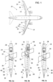
- An aircraft 10 as shown in Fig. 1 has a pair of aircraft wings 12 extending from a fuselage. Each wing 12 has a leading edge 14 and a trailing edge 16. High-lift systems 18 are arranged at the trailing edge 16. Each high-lift system 18 comprises a high-lift mechanism 20 and fairing arrangements 26.
- the high-lift mechanism 20 includes a flap 22 and several mounting and guiding mechanisms 24 for mounting the flap 22 at the trailing edge 16 and guiding a movement of the flap 22.
- the mounting and guiding mechanism 24 serves as flap support.
- the mounting and guiding mechanism 24 includes a flap track for guiding the movement of the flap. Any of the mounting and guiding mechanisms 24 is aerodynamically covered by a fairing arrangement 26.
- the wing 12 has a variable shape trailing edge functionality (VSTE) where the trailing edge 16 has a variable shape and can be deformed for different flight situations.
- VSTE variable shape trailing edge functionality
- Fig. 2a, 2b, 2c , 3a, 3b, and 3c show an embodiment of the fairing arrangement 26 in different flap positions, wherein Figs. 2a and 3a show a clean configuration wherein the flap 22 is retracted, Figs. 2b and 3c show a high-lift configuration where the flap 22 is fully extended, and Figs. 2c and 3c show a negative VSTE configuration.
- the high-lift mechanism 20 includes the flap 22 to be arranged at a trailing edge 16 of the aircraft wing 12 and the mounting and guiding mechanism 24 for the flap 22.
- the fairing arrangement 26 comprises a flap side fairing unit 28 and a wing side fairing unit 30.
- the flap side fairing unit 28 is an aft fairing unit and the wing side fairing unit is a forward fairing unit.
- the flap side fairing unit 28 comprises a flap side fairing 32 for covering an aft part of the mounting and guiding mechanism 24 and a flap side fairing mount 34 for mounting the flap side fairing 32 to the flap 22.
- the flap side fairing mount 34 is configured to mount the flap side fairing 32 rigidly to the flap 22.
- the shell of the flap side fairing 32 may be mounted with usual bolts, rivets or fasteners (not shown) to the flap 22.
- the wing side fairing unit 30 comprises a wing side fairing 36 for covering a forward part of the mounting and guiding mechanism 24 and a wing side fairing mount 38 for mounting the wing side fairing 36 to the wing.
- the wing side fairing mount 38 is configured to connect the wing side fairing 36 to the wing 12 or the front part of the mounting and guiding mechanism 24 which is attached to the wing 12 such that it is rotatable around an essentially vertical axis 39 directed at least with its largest direction component in a vertical direction.
- the vertical direction is the direction essentially perpendicular to the spanwise and chordwise directions of the wing 12 (i.e., the direction of lift).
- a U-channel shaped forward end portion 56 of the flap side fairing 32 engages into a U-channel shaped rearward end portion 58 of the wing side fairing 36 in order to allow a telescopic and rotational relative movement of said fairings.
- the extension and design of the end portions 56, 58 is such that they engage into each other in all flap configurations.
- the Figs. 3a to 3c show the high lift configurations in a side view.
- the flap side fairing 32 is in all configurations in contact with the wing side fairing 36.
- the contact surface is defined in a way that the lateral movement of the flap side fairing 32 guides the rotational position of the wing side fairing 36.
- Figs. 4 to 10 show the fairing arrangement 26 according to a first to fourth embodiment with different designs of the wing side fairing mount 38.
- the wing side fairing mount 38 comprises a forward connecting mechanism 40 and a rearward connecting mechanism 42.
- the forward connecting mechanism 40 is configured to connect a forward part of the wing side fairing 36 rotatably with one degree of freedom or with two degrees of freedom to the mounting and guiding mechanism 24.
- the forward connecting mechanism 40 just has a simple bearing allowing rotation of the wing side fairing around the essentially vertical axis 39.
- the forward connecting mechanism is essentially comprised of a bearing allowing rotation about the essentially vertical axis 39 and further allowing rotation about a second axis 44 perpendicular to this essentially vertical axis 39.
- the bearing is a spherical bearing 46.
- the spherical bearing 46 includes a ball portion 48, a shaft portion and a spherical bearing shell 50.
- a forward part of the fairing shell of the wing side fairing 36 is hold on ends of the shaft portion 48.
- the ball portion 48 is integrally formed with or rigidly connected to a centre of the shaft portion 48 and is hold in the spherical bearing shell 50.
- the spherical bearing shell is fixed to a track member 52 of the mounting and guiding mechanism 24 which itself is, in use, fixed to the structure of the wing 12.
- the rearward connecting mechanism 42 is configured to allow a movement of the rearward part of the wing side fairing 36 in a spanwise direction during the rotational movement about the essentially vertical axis 39.
- Several possible designs of the rearward connecting mechanism 42 are provided in the first to fourth embodiment as shown in Figs. 4 to 10 .
- the rearward connecting mechanism 42 comprises a pair of parallel swing struts 60.1, 60.2.
- the wing side fairing 36 i.e., a forward fairing of the fairing arrangement 26
- the two parallel fairing struts 60.1, 60.2 are located to lock the rotational degree of freedom around an axis in line of flight and around an axis in spanwise direction.
- the resulting movement is not a pure rotation around the vertical axis 39 but more a complex combination of rotations.
- the required rotation of the wing side fairing 36 is limited to just a few degrees and the here described movement is working well as a design solution.
- the swing struts 60.1, 60.2 are equipped with multi-axis bearings such as spherical bearings 61 at their ends in order to connect the strut ends movably to the track member 52 and the wing side fairing 36, respectively.
- the struts 60.1, 60.2 can be replaced by flexible tensile means or flexible elements like steel cables in combination with a roller or linear bearing below the track member 52.
- the rearward connecting mechanism 42 comprises an upper track and roller arrangement 62.1 and a lower track and roller arrangement 62.2.
- the track and roller arrangements 62.1, 62.2 comprise rollers 64.1, 64.2 rotatably mounted on a roller support 66, e.g., a fairing bridge 67, at an inside the wing side fairing 36 and allowing movement of the aft part of the wing side fairing 36 in the spanwise direction.
- a roller support 66 e.g., a fairing bridge 67
- sliders are used instead of some or all of the rollers 64.1, 64.2.
- the wing side fairing 36 is connected to the wing structure 65 with the spherical bearing 46 as explained above and a combination of two rollers 64.1 above the track member 52 and two rollers 64.2 below the track member 52.
- linear bearings 68 can be used instead of rollers 64.1, 64.2.
- the rearward connecting mechanism 42 comprises a curved track 70 and rollers 72 running on that curved track 70.
- the curved track 70 is fixed inside the wing side fairing 36 and the rollers 72 are rotatably mounted on a bottom surface of the mounting and guiding mechanism 24, especially the track member 52.
- the rollers 72 are rotatably mounted in the wing side fairing 30 while the track 70 is mounted on the mounting and guiding mechanism 24.
- the aft guidance of the wing side fairing 36 is realized by a set of rollers 72 running on the curved track 70 with the track center point in line with the vertical rotation axis 39.
- the fairing arrangement 26 comprises a fixed front fairing unit 74 configured to be rigidly fixed to the wing 12, wherein the wing side fairing unit 30 is configured as intermediate movable wing side fairing unit arranged between fixed front fairing unit 74 and the flap side fairing unit 28.
- a forward fairing for covering a front part of the mounting and guiding mechanism 24 is splitted into a fixed fairing 76 and the wing side fairing 36, here configured as an intermediate fairing 78.
- the intermediate fairing 78 is mounted with the forward connecting mechanism 40 and the rearward connecting mechanism 42.
- the rearward connecting mechanism 42 includes the linear bearing 68 allowing movement of the aft part of the intermediate fairing 78 in spanwise direction for rotation of this intermediate bearing 78 about the essentially vertical axis 39, but of course the rearward connecting mechanism 42 could also have the design of any of the other embodiments as explained above.
- the rearward connecting mechanism 42 may comprise any combination of swing struts, tensile means, cables, linear bearings, track and roller or slider arrangements.
- the wing side fairing unit (30) comprises a wing side fairing (36) for covering a forward part of the mounting and guiding mechanism (24) and a wing side fairing mount (38) for mounting the wing side fairing (36) to the wing (12).
- the wing side fairing mount (38) is configured for connecting the wing side fairing (36) movably to the wing (12) such that the wing side fairing (36) is rotatable around an axis (39) directed at least partially in a vertical direction.
Landscapes
- Engineering & Computer Science (AREA)
- Aviation & Aerospace Engineering (AREA)
- Mechanical Engineering (AREA)
- Transmission Devices (AREA)
Abstract
Description
- The invention relates to a fairing arrangement for a high-lift mechanism of an aircraft, wherein the high-lift mechanism includes a flap to be arranged at a trailing edge of an aircraft wing and a mounting and guiding mechanism for the flap. Further the invention relates to a high-lift system, an aircraft wing and an aircraft comprising such fairing arrangement.
- With regard to prior art, reference is made to the following citations:
-
US 2022 306 274 A1 -
US 2021 316 840 A1 -
US 2016 068 255 A1 -
EP 2 516 257 B1 - Airbus press release of September 22, 2021,
https://www.airbus.com/en/newsroom/press-releases/2021-09-airbus-launches-extra-high-performance-wing-demonstrator-to-fortify - Airbus press release of April 12, 2022,
https://www.airbus.com/en/newsroom/press-releases/2022-04-nature-inspired-wing-demonstrator-completes-wind-tunnel-tests - [1] to [4] disclose a fairing arrangement for a high-lift mechanism of an aircraft, wherein the high-lift mechanism includes a flap to be arranged at a trailing edge of an aircraft wing and a mounting and guiding mechanism for the flap, the fairing arrangement comprising a flap side fairing unit and a wing side fairing unit, the flap side fairing unit comprising a flap side fairing for covering an aft part of the mounting and guiding mechanism and a flap side fairing mount for movably mounting the flap side fairing to the flap, the wing side fairing unit comprising a wing side fairing for covering a forward part of the mounting and guiding mechanism and a wing side fairing mount for mounting the wing side fairing in a rigidly fixed manner to the wing.
- An object of the invention is to functionally improve such fairing arrangements.
- For achieving such object, the invention provides a fairing arrangement according to claim 1. Advantageous uses of the fairing arrangement are given in the further independent claims.
- Advantageous embodiments are subject-matters of the dependent claims.
- The invention provides a fairing arrangement for a high-lift mechanism of an aircraft, wherein the high-lift mechanism includes a flap to be arranged at a trailing edge of an aircraft wing and a mounting and guiding mechanism for the flap,
- the fairing arrangement comprising a flap side fairing unit and a wing side fairing unit,
- the flap side fairing unit comprising a flap side fairing for covering an aft part of the mounting and guiding mechanism and a flap side fairing mount for mounting the flap side fairing to the flap,
- the wing side fairing unit comprising a wing side fairing for covering a forward part of the mounting and guiding mechanism and a wing side fairing mount for mounting the wing side fairing to the wing,
- wherein the wing side fairing mount is configured to connect the wing side fairing such that it is rotatable around an axis directed at least partially in a vertical direction.
- Preferably, the wing side fairing unit is configured such that a rear part of the wing side fairing to be engaged with the flap side fairing is movable in a limited predefined manner in a spanwise direction.
- Preferably, the wing side fairing mount comprises a forward connecting mechanism configured to connect a forward part of the wing side fairing rotatably with at least one or with two degrees of freedom to the mounting and guiding mechanism.
- Preferably, the forward connecting mechanism includes a spherical bearing. Preferably, the forward connecting mechanism allows movement of a forward part of the wing side fairing in at least two degrees of freedom, especially by a rotation about a first axis that has at least a direction component in the vertical direction (e.g., the vertical direction is the lift direction of the wing) and by a rotation about a second axis extending or essentially extending in the flight direction.
- Preferably, the wing side fairing mount comprises a rearward connecting mechanism configured to connect a rearward part of the wing side fairing such that it is movable in a spanwise direction.
- Preferably, the rearward connecting mechanism includes a swing strut. Preferably, the rearward connecting mechanism includes a pair of parallel swing struts. Preferably, the rearward connecting mechanism includes a tensile means, i.e., flexible means such as a cable or a chain. Preferably, the rearward connecting mechanism includes an arrangement of a track and rollers or sliders. Preferably, the rearward connecting mechanism includes an upper track and roller or slider arrangement and/or a lower track and roller or slider arrangement. Preferably, the rearward connecting mechanism includes a track curved around a rotation axis of the forward connecting mechanism in combination with a set of rollers or sliders running on the track. Preferably, the rearward connecting mechanism includes a linear bearing.
- Preferably, a forward end portion of the flap side fairing engages into a rearward end portion of the wing side fairing in order to allow a telescopic and rotational relative movement of said fairings.
- Preferably, the fairing arrangement further comprises a fixed front fairing unit configured to be rigidly fixed to the wing, wherein the wing side fairing unit is configured as intermediate movable wing side fairing unit arranged between fixed front fairing unit and the flap side fairing unit.
- According to another aspect, the invention provides a high-lift system for an aircraft, comprising
- a high-lift mechanism including a flap to be arranged at a trailing edge of an aircraft wing and a mounting and guiding mechanism for the flap (also called flap support in the prior art), and
- a fairing arrangement according to any of the aforementioned embodiments.
- According to another aspect, the invention provides an aircraft wing comprising such a high-lift system and/or a fairing arrangement according to any of the aforementioned embodiments.
- According to another aspect, the invention provides an aircraft, comprising a wing arrangement including such a wing and/or such a high-lift system and/or a fairing arrangement according to any of the aforementioned embodiments.
- The invention lies on the technical field of aircraft high-lift systems and especially relates to fairings of such high-lift systems.
- Preferred embodiments of the invention propose improved fairing kinematics for a variable shape trailing edge.
- Preferred embodiments of the invention relate to a type of fairing arrangement that is kinematically configured to translate and rotate.
- In known fairing solutions such as mentioned above, a forward part of the fairing is rigidly assembled to the wing and the aft part of the fairing has a hinged connection to a flap support beam.
- Preferred embodiments provide at least one, several or all of the following advantages:
- an interface of a rear part of the fairing and flap is much simpler
- a lateral movement of the flap system can be compensated
- a solution proposed by preferred embodiments may be a key enabler for a variable shape trailing edge functionality (VSTE) as demonstrated on eXtra performance Wing demonstrator, see [5] and [6]
- ensures a good aerodynamic condition between forward and aft part of the fairing
- The positional determination of the forward fairing is steered by the engagement of the forward fairing into the forward fairing
- Also more or fully sealed conditions in all high lift configurations can be realized
- Embodiments of the invention are explained below referring to the accompanying drawings in which:
- Fig. 1
- is a plan view of an aircraft;
- Fig. 2a
- is a top plan view of a fairing arrangement of the aircraft in a clean configuration (flap retracted);
- Fig. 2b
- is a view as in
Fig. 2a of the fairing arrangement in a high-lift configuration (flap fully extended); - Fig. 2c
- is a view as in
Fig. 2a and 2b of the fairing arrangement in a negative variable shape trailing edge configuration; - Fig. 3a
- is a side view of the fairing arrangement of the aircraft in the clean configuration (flap retracted);
- Fig. 3b
- is a view as in
Fig. 3a of the fairing arrangement in a high-lift configuration (flap fully extended); - Fig. 3c
- is a view as in
Fig. 3a and 3b of the fairing arrangement in a negative variable shape trailing edge configuration; - Fig. 4
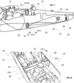
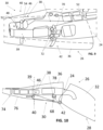
- is a side view of a high-lift system including a first embodiment of a fairing arrangement wherein fairings thereof are shown partly broken away for illustrative purposes;
- Fig. 5
- a first perspective rear and side view of a wing side fairing unit of the fairing arrangement of the first embodiment;
- Fig. 6
- a second perspective rear and side view of the wing side fairing unit of the fairing arrangement of the first embodiment;
- Fig. 7
- a side view of the wing side fairing unit of the fairing arrangement according to a second embodiment, wherein a fairing shell is shown partly broken away for illustrative purposes;
- Fig. 8
- a perspective view seen from above and a side of the wing side fairing unit of the fairing arrangement according to the second embodiment;
- Fig. 9
- a perspective view seen from below and from a side of the wing side fairing unit of the fairing arrangement according to a third embodiment wherein a fairing shell is indicated in broken lines only; and
- Fig. 10
- a side view of the fairing arrangement according to a fourth embodiment.
- An
aircraft 10 as shown inFig. 1 has a pair ofaircraft wings 12 extending from a fuselage. Eachwing 12 has aleading edge 14 and a trailingedge 16. High-lift systems 18 are arranged at the trailingedge 16. Each high-lift system 18 comprises a high-lift mechanism 20 andfairing arrangements 26. The high-lift mechanism 20 includes aflap 22 and several mounting and guidingmechanisms 24 for mounting theflap 22 at the trailingedge 16 and guiding a movement of theflap 22. The mounting and guidingmechanism 24 serves as flap support. In some embodiments, the mounting and guidingmechanism 24 includes a flap track for guiding the movement of the flap. Any of the mounting and guidingmechanisms 24 is aerodynamically covered by afairing arrangement 26. - According to some embodiments, the
wing 12 has a variable shape trailing edge functionality (VSTE) where the trailingedge 16 has a variable shape and can be deformed for different flight situations. -
Fig. 2a, 2b, 2c ,3a, 3b, and 3c show an embodiment of thefairing arrangement 26 in different flap positions, whereinFigs. 2a and3a show a clean configuration wherein theflap 22 is retracted,Figs. 2b and3c show a high-lift configuration where theflap 22 is fully extended, andFigs. 2c and3c show a negative VSTE configuration. - Referring to
Figs. 2a-2c and3a-3c , there is shown thefairing arrangement 26 for the high-lift mechanism 20 of theaircraft 10. The high-lift mechanism 20 includes theflap 22 to be arranged at a trailingedge 16 of theaircraft wing 12 and the mounting and guidingmechanism 24 for theflap 22. - The
fairing arrangement 26 comprises a flapside fairing unit 28 and a wingside fairing unit 30. As seen in flight direction of theaircraft 10, the flapside fairing unit 28 is an aft fairing unit and the wing side fairing unit is a forward fairing unit. - The flap
side fairing unit 28 comprises a flap side fairing 32 for covering an aft part of the mounting and guidingmechanism 24 and a flapside fairing mount 34 for mounting the flap side fairing 32 to theflap 22. In the embodiments shown, the flapside fairing mount 34 is configured to mount the flap side fairing 32 rigidly to theflap 22. For example the shell of the flap side fairing 32 may be mounted with usual bolts, rivets or fasteners (not shown) to theflap 22. - The wing
side fairing unit 30 comprises a wing side fairing 36 for covering a forward part of the mounting and guidingmechanism 24 and a wingside fairing mount 38 for mounting the wing side fairing 36 to the wing. The wingside fairing mount 38 is configured to connect the wing side fairing 36 to thewing 12 or the front part of the mounting and guidingmechanism 24 which is attached to thewing 12 such that it is rotatable around an essentiallyvertical axis 39 directed at least with its largest direction component in a vertical direction. Here, the vertical direction is the direction essentially perpendicular to the spanwise and chordwise directions of the wing 12 (i.e., the direction of lift). - As further shown in
Figs. 2a to 3c , a U-channel shapedforward end portion 56 of the flap side fairing 32 engages into a U-channel shapedrearward end portion 58 of the wing side fairing 36 in order to allow a telescopic and rotational relative movement of said fairings. In some embodiments, the extension and design of theend portions Figs. 3a to 3c show the high lift configurations in a side view. The flap side fairing 32 is in all configurations in contact with thewing side fairing 36. The contact surface is defined in a way that the lateral movement of the flap side fairing 32 guides the rotational position of thewing side fairing 36. -
Figs. 4 to 10 show thefairing arrangement 26 according to a first to fourth embodiment with different designs of the wingside fairing mount 38. Referring toFigs. 4 to 10 , the wingside fairing mount 38 comprises a forward connectingmechanism 40 and a rearward connectingmechanism 42. - The forward connecting
mechanism 40 is configured to connect a forward part of the wing side fairing 36 rotatably with one degree of freedom or with two degrees of freedom to the mounting and guidingmechanism 24. - In an embodiment not shown, the forward connecting
mechanism 40 just has a simple bearing allowing rotation of the wing side fairing around the essentiallyvertical axis 39. - In the embodiments shown in
Figs. 4 to 10 the forward connecting mechanism is essentially comprised of a bearing allowing rotation about the essentiallyvertical axis 39 and further allowing rotation about asecond axis 44 perpendicular to this essentiallyvertical axis 39. For example, the bearing is aspherical bearing 46. In some embodiments, thespherical bearing 46 includes aball portion 48, a shaft portion and aspherical bearing shell 50. A forward part of the fairing shell of the wing side fairing 36 is hold on ends of theshaft portion 48. Theball portion 48 is integrally formed with or rigidly connected to a centre of theshaft portion 48 and is hold in thespherical bearing shell 50. The spherical bearing shell is fixed to atrack member 52 of the mounting and guidingmechanism 24 which itself is, in use, fixed to the structure of thewing 12. - The rearward connecting
mechanism 42 is configured to allow a movement of the rearward part of the wing side fairing 36 in a spanwise direction during the rotational movement about the essentiallyvertical axis 39. Several possible designs of the rearward connectingmechanism 42 are provided in the first to fourth embodiment as shown inFigs. 4 to 10 . - In a first embodiment as shown in
Figs. 4 to 6 , the rearward connectingmechanism 42 comprises a pair of parallel swing struts 60.1, 60.2. Hence, in the first embodiment, the wing side fairing 36 (i.e., a forward fairing of the fairing arrangement 26) is in the rotational axis connected to thewing structure 65 by thespherical bearing 46. In an aft area of the wing side fairing 36 the two parallel fairing struts 60.1, 60.2 are located to lock the rotational degree of freedom around an axis in line of flight and around an axis in spanwise direction. The resulting movement is not a pure rotation around thevertical axis 39 but more a complex combination of rotations. The required rotation of the wing side fairing 36 is limited to just a few degrees and the here described movement is working well as a design solution. - The swing struts 60.1, 60.2 are equipped with multi-axis bearings such as
spherical bearings 61 at their ends in order to connect the strut ends movably to thetrack member 52 and the wing side fairing 36, respectively. - As a variation (not shown) the struts 60.1, 60.2 can be replaced by flexible tensile means or flexible elements like steel cables in combination with a roller or linear bearing below the
track member 52. - In a second embodiment as shown in
Figs. 7 and 8 , the rearward connectingmechanism 42 comprises an upper track and roller arrangement 62.1 and a lower track and roller arrangement 62.2. The track and roller arrangements 62.1, 62.2 comprise rollers 64.1, 64.2 rotatably mounted on aroller support 66, e.g., a fairingbridge 67, at an inside the wing side fairing 36 and allowing movement of the aft part of the wing side fairing 36 in the spanwise direction. In a variant not shown, sliders are used instead of some or all of the rollers 64.1, 64.2. In the second embodiment, the wing side fairing 36 is connected to thewing structure 65 with thespherical bearing 46 as explained above and a combination of two rollers 64.1 above thetrack member 52 and two rollers 64.2 below thetrack member 52. As a variation of this solution which is illustrated schematically inFig. 10 for the fourth embodiment, alsolinear bearings 68 can be used instead of rollers 64.1, 64.2. - In a third embodiment as shown in
Fig. 9 , the rearward connectingmechanism 42 comprises acurved track 70 androllers 72 running on thatcurved track 70. In the embodiment shown, thecurved track 70 is fixed inside the wing side fairing 36 and therollers 72 are rotatably mounted on a bottom surface of the mounting and guidingmechanism 24, especially thetrack member 52. In other embodiments (not shown), therollers 72 are rotatably mounted in the wing side fairing 30 while thetrack 70 is mounted on the mounting and guidingmechanism 24. In the third embodiment, the aft guidance of the wing side fairing 36 is realized by a set ofrollers 72 running on thecurved track 70 with the track center point in line with thevertical rotation axis 39. - In the fourth embodiment as shown in
Fig. 10 , an alternative arrangement of thefairings fairing arrangement 26 comprises a fixedfront fairing unit 74 configured to be rigidly fixed to thewing 12, wherein the wingside fairing unit 30 is configured as intermediate movable wing side fairing unit arranged between fixedfront fairing unit 74 and the flapside fairing unit 28. - In other words, a forward fairing for covering a front part of the mounting and guiding
mechanism 24 is splitted into a fixedfairing 76 and the wing side fairing 36, here configured as anintermediate fairing 78. Theintermediate fairing 78 is mounted with the forward connectingmechanism 40 and the rearward connectingmechanism 42. In the fourth embodiment, the rearward connectingmechanism 42 includes thelinear bearing 68 allowing movement of the aft part of theintermediate fairing 78 in spanwise direction for rotation of thisintermediate bearing 78 about the essentiallyvertical axis 39, but of course the rearward connectingmechanism 42 could also have the design of any of the other embodiments as explained above. - The different features of different embodiments can be combined as needed. For example, the rearward connecting
mechanism 42 may comprise any combination of swing struts, tensile means, cables, linear bearings, track and roller or slider arrangements. - A functionally improved fairing arrangement (26) for a high-lift mechanism (20) of an aircraft (10) has been described. The high-lift mechanism (20) includes a flap (22) to be arranged at a trailing edge (16) of an aircraft wing (12) and a mounting and guiding mechanism (24) for the flap (26). The fairing arrangement (26) comprises a flap side fairing unit (28) and a wing side fairing unit (30). The flap side fairing unit (28) comprises a flap side fairing (32) for covering an aft part of the mounting and guiding mechanism (24) and a flap side fairing mount (34) for mounting the flap side fairing (32) to the flap (22). The wing side fairing unit (30) comprises a wing side fairing (36) for covering a forward part of the mounting and guiding mechanism (24) and a wing side fairing mount (38) for mounting the wing side fairing (36) to the wing (12). The wing side fairing mount (38) is configured for connecting the wing side fairing (36) movably to the wing (12) such that the wing side fairing (36) is rotatable around an axis (39) directed at least partially in a vertical direction.
-
- 10
- aircraft
- 12
- wing
- 14
- leading edge
- 16
- trailing edge
- 18
- high-lift system
- 20
- high-lift mechanism
- 22
- flap
- 24
- mounting and guiding mechanism
- 26
- fairing arrangement
- 28
- flap side fairing unit
- 30
- wing side fairing unit
- 32
- flap side fairing
- 34
- flap side fairing mount
- 36
- wing side fairing
- 38
- wing side fairing mount
- 39
- vertical axis
- 40
- forward connecting mechanism
- 42
- rearward connecting mechanism
- 44
- second axis
- 46
- spherical bearing
- 48
- ball portion
- 50
- bearing shell
- 52
- track member
- 54
- shaft portion
- 56
- forward end portion
- 58
- rearward end portion
- 60.1
- first swing strut
- 60.2
- second swing strut
- 61
- spherical bearing at end of strut
- 62.1
- upper track and roller arrangement
- 62.2
- lower track and roller arrangement
- 64.1
- upper roller
- 64.2
- lower roller
- 65
- wing structure
- 66
- roller support
- 67
- fairing bridge
- 68
- linear bearing
- 70
- curved track
- 72
- roller
- 74
- fixed front fairing unit
- 76
- forward fairing
- 78
- intermediate fairing
Claims (10)
- Fairing arrangement (26) for a high-lift mechanism (20) of an aircraft (10), wherein the high-lift mechanism (20) includes a flap (22) to be arranged at a trailing edge (16) of an aircraft wing (12) and a mounting and guiding mechanism (24) for the flap (26),the fairing arrangement (26) comprising a flap side fairing unit (28) and a wing side fairing unit (30),the flap side fairing unit (28) comprising a flap side fairing (32) for covering an aft part of the mounting and guiding mechanism (24) and a flap side fairing mount (34) for mounting the flap side fairing (32) to the flap (22),the wing side fairing unit (30) comprising a wing side fairing (36) for covering a forward part of the mounting and guiding mechanism (24) and a wing side fairing mount (38) for mounting the wing side fairing (36) to the wing (12),wherein the wing side fairing mount (38) is configured for connecting the wing side fairing (36) movably to the wing (12) such that the wing side fairing (36) is rotatable around an axis (39) directed at least partially in a vertical direction.
- Fairing arrangement (26) according to claim 1, characterized in that the wing side fairing mount (38) comprises a forward connecting mechanism (40) configured to connect a forward part of the wing side fairing (36) rotatably with at least one or with two degrees of freedom to the mounting and guiding mechanism (24).
- Fairing arrangement (26) according to claim 2, characterized in that the forward connecting mechanism (40) includes a multi-axis bearing or a spherical bearing (46).
- Fairing arrangement (26) according to any of the preceding claims, characterized in that the wing side fairing mount (38) comprises a rearward connecting mechanism (42) configured to connect a rearward part of the wing side fairing (32) such that it is movable in a spanwise direction.
- Fairing arrangement (26) according to claim 4, characterized in that the rearward connecting mechanism (42) includes at least one or several of the group consisting of a swing strut (60.1, 60.2), a pair of parallel swing struts (60.1, 60.2), a tensile means, a cable, an arrangement (62.1, 62.2) of a track and rollers (64.1, 64.2) or sliders, an upper track and roller or slider arrangement (62.1), a lower track and roller or slider arrangement (62.2), a track (70) curved around the rotation axis (39) of the forward connecting mechanism (40) in combination with a set of rollers (72) or sliders running on the curved track (70), and a linear bearing (68).
- Fairing arrangement (26) according to any of the preceding claims, characterized in that a forward end portion (56) of the flap side fairing (32) engages into a rearward end portion (58) of the wing side fairing (36) in order to allow a telescopic and rotational relative movement of said fairings (32, 36).
- Fairing arrangement (26) according to any of the preceding claims, characterized by a fixed front fairing unit (74) configured to be rigidly fixed to the wing (12), wherein the wing side fairing unit (30) is configured as intermediate movable wing side fairing unit arranged between fixed front fairing unit (74) and the flap side fairing unit (28).
- High-lift system (18) for an aircraft (10), comprisinga high-lift mechanism (20) including a flap (22) to be arranged at a trailing edge (16) of an aircraft wing (12) and a mounting and guiding mechanism (24) for the flap (22), anda fairing arrangement (26) according to any of the preceding claims.
- Aircraft wing (12) comprising a high-lift system (18) according to claim 8 and/or a fairing arrangement (26) according to any of the claims 1 to 7.
- Aircraft (10), comprising a wing (12) according to claim 9, a high-lift system (18) according to claim 8 and/or a fairing arrangement (26) according to any of the claims 1 to 7.
Priority Applications (3)
| Application Number | Priority Date | Filing Date | Title |
|---|---|---|---|
| EP22214915.5A EP4389594B1 (en) | 2022-12-20 | 2022-12-20 | Fairing arrangement for a high-lift mechanism of an aircraft |
| CN202311710666.1A CN118220494A (en) | 2022-12-20 | 2023-12-13 | Fairing device for high lift mechanism of aircraft |
| US18/543,103 US12319408B2 (en) | 2022-12-20 | 2023-12-18 | Fairing arrangement for a high-lift mechanism of an aircraft |
Applications Claiming Priority (1)
| Application Number | Priority Date | Filing Date | Title |
|---|---|---|---|
| EP22214915.5A EP4389594B1 (en) | 2022-12-20 | 2022-12-20 | Fairing arrangement for a high-lift mechanism of an aircraft |
Publications (2)
| Publication Number | Publication Date |
|---|---|
| EP4389594A1 true EP4389594A1 (en) | 2024-06-26 |
| EP4389594B1 EP4389594B1 (en) | 2025-09-24 |
Family
ID=84541637
Family Applications (1)
| Application Number | Title | Priority Date | Filing Date |
|---|---|---|---|
| EP22214915.5A Active EP4389594B1 (en) | 2022-12-20 | 2022-12-20 | Fairing arrangement for a high-lift mechanism of an aircraft |
Country Status (3)
| Country | Link |
|---|---|
| US (1) | US12319408B2 (en) |
| EP (1) | EP4389594B1 (en) |
| CN (1) | CN118220494A (en) |
Citations (4)
| Publication number | Priority date | Publication date | Assignee | Title |
|---|---|---|---|---|
| US20160068255A1 (en) * | 2011-10-07 | 2016-03-10 | Airbus Operations Limited | Flap support |
| US20170158310A1 (en) * | 2015-12-03 | 2017-06-08 | The Boeing Company | Aircraft wing fairing drive assembly, system, and method |
| EP3434583B1 (en) * | 2017-07-28 | 2020-12-23 | The Boeing Company | Articulation assemblies for retracting aircraft flap support fairings and related methods |
| US20210316840A1 (en) * | 2018-08-20 | 2021-10-14 | Airbus Defence and Space GmbH | Flap support for supporting a flap of a wing for an aircraft |
Family Cites Families (6)
| Publication number | Priority date | Publication date | Assignee | Title |
|---|---|---|---|---|
| DE3641247A1 (en) * | 1986-12-03 | 1988-06-16 | Messerschmitt Boelkow Blohm | LANDING VALVE GUIDE RAIL FAIRING FOR AIRCRAFT |
| DE102009060082A1 (en) | 2009-12-22 | 2011-06-30 | Airbus Operations GmbH, 21129 | A wing assembly with an adjustable flap and trim element for covering a flap adjustment mechanism of a wing |
| US11192628B2 (en) * | 2019-06-30 | 2021-12-07 | The Boeing Company | Articulated flap support forward fairing |
| GB2605197B (en) | 2021-03-26 | 2023-12-13 | Airbus Operations Ltd | Aircraft wing with trailing edge panel |
| EP4410667B1 (en) * | 2023-01-31 | 2025-06-25 | Airbus Operations GmbH | Flap system for an aircraft and method of operating a flap fairing at an aircraft wing |
| EP4446217B1 (en) * | 2023-04-11 | 2026-01-21 | Airbus Operations GmbH | Fairing arrangement for a high-lift mechanism of an aircraft |
-
2022
- 2022-12-20 EP EP22214915.5A patent/EP4389594B1/en active Active
-
2023
- 2023-12-13 CN CN202311710666.1A patent/CN118220494A/en active Pending
- 2023-12-18 US US18/543,103 patent/US12319408B2/en active Active
Patent Citations (4)
| Publication number | Priority date | Publication date | Assignee | Title |
|---|---|---|---|---|
| US20160068255A1 (en) * | 2011-10-07 | 2016-03-10 | Airbus Operations Limited | Flap support |
| US20170158310A1 (en) * | 2015-12-03 | 2017-06-08 | The Boeing Company | Aircraft wing fairing drive assembly, system, and method |
| EP3434583B1 (en) * | 2017-07-28 | 2020-12-23 | The Boeing Company | Articulation assemblies for retracting aircraft flap support fairings and related methods |
| US20210316840A1 (en) * | 2018-08-20 | 2021-10-14 | Airbus Defence and Space GmbH | Flap support for supporting a flap of a wing for an aircraft |
Also Published As
| Publication number | Publication date |
|---|---|
| US12319408B2 (en) | 2025-06-03 |
| CN118220494A (en) | 2024-06-21 |
| EP4389594B1 (en) | 2025-09-24 |
| US20240199196A1 (en) | 2024-06-20 |
Similar Documents
| Publication | Publication Date | Title |
|---|---|---|
| US4995575A (en) | Wing trailing edge flap mechanism | |
| EP3134314B1 (en) | An aircraft with a foldable wing tip device | |
| EP0184230B1 (en) | Aircraft trailing edge flap apparatus | |
| EP2134597B1 (en) | Wing | |
| US5207400A (en) | Flap assembly | |
| EP2104628B1 (en) | A leading edge structure for an aerofoil | |
| EP0154047A1 (en) | Wing flap mechanism | |
| US4854528A (en) | Cover for flap guide rails in aircraft wings | |
| US11591067B2 (en) | Rotating double trapped roller auxiliary track mechanism | |
| EP0781704A1 (en) | Vortex leading edge flap assembly for supersonic airplanes | |
| US11753149B2 (en) | Landing gear door system for a landing gear compartment | |
| EP2886451A1 (en) | Trailing-edge flap system for a wing of an aircraft and aircraft comprising a wing and at least one such trailing-edge flap system | |
| EP4140878B1 (en) | Leading edge high lift assembly and wing for an aircraft | |
| US20240343380A1 (en) | Fairing arrangement for a high-lift mechanism of an aircraft | |
| EP3301017A1 (en) | System for driving and guiding of a trailing edge control surface | |
| EP4389594B1 (en) | Fairing arrangement for a high-lift mechanism of an aircraft | |
| US5110072A (en) | Control surface stabilizer hinge | |
| EP1972547A1 (en) | Wing leading edge device | |
| EP0081610B1 (en) | Flap assembly aircraft wing | |
| EP4303122A1 (en) | Wing for an aircraft | |
| RU2353545C2 (en) | Device and method of bringing rotary elements into operation | |
| EP4269232B1 (en) | Fairing attachment system for a wing of an aircraft, aircraft wing and method for mounting a fairing device | |
| EP3931081B1 (en) | A wing leading-edge device and a wing having such a wing leading-edge device | |
| US12365441B2 (en) | Spoiler | |
| US11878794B2 (en) | Aircraft wing trailing edge section assembly |
Legal Events
| Date | Code | Title | Description |
|---|---|---|---|
| PUAI | Public reference made under article 153(3) epc to a published international application that has entered the european phase |
Free format text: ORIGINAL CODE: 0009012 |
|
| STAA | Information on the status of an ep patent application or granted ep patent |
Free format text: STATUS: THE APPLICATION HAS BEEN PUBLISHED |
|
| AK | Designated contracting states |
Kind code of ref document: A1 Designated state(s): AL AT BE BG CH CY CZ DE DK EE ES FI FR GB GR HR HU IE IS IT LI LT LU LV MC ME MK MT NL NO PL PT RO RS SE SI SK SM TR |
|
| STAA | Information on the status of an ep patent application or granted ep patent |
Free format text: STATUS: REQUEST FOR EXAMINATION WAS MADE |
|
| 17P | Request for examination filed |
Effective date: 20241213 |
|
| GRAP | Despatch of communication of intention to grant a patent |
Free format text: ORIGINAL CODE: EPIDOSNIGR1 |
|
| STAA | Information on the status of an ep patent application or granted ep patent |
Free format text: STATUS: GRANT OF PATENT IS INTENDED |
|
| INTG | Intention to grant announced |
Effective date: 20250422 |
|
| GRAS | Grant fee paid |
Free format text: ORIGINAL CODE: EPIDOSNIGR3 |
|
| GRAA | (expected) grant |
Free format text: ORIGINAL CODE: 0009210 |
|
| STAA | Information on the status of an ep patent application or granted ep patent |
Free format text: STATUS: THE PATENT HAS BEEN GRANTED |
|
| AK | Designated contracting states |
Kind code of ref document: B1 Designated state(s): AL AT BE BG CH CY CZ DE DK EE ES FI FR GB GR HR HU IE IS IT LI LT LU LV MC ME MK MT NL NO PL PT RO RS SE SI SK SM TR |
|
| REG | Reference to a national code |
Ref country code: GB Ref legal event code: FG4D |
|
| REG | Reference to a national code |
Ref country code: CH Ref legal event code: EP |
|
| REG | Reference to a national code |
Ref country code: DE Ref legal event code: R096 Ref document number: 602022021910 Country of ref document: DE |
|
| REG | Reference to a national code |
Ref country code: IE Ref legal event code: FG4D |
|
| PGFP | Annual fee paid to national office [announced via postgrant information from national office to epo] |
Ref country code: DE Payment date: 20251211 Year of fee payment: 4 |
|
| PG25 | Lapsed in a contracting state [announced via postgrant information from national office to epo] |
Ref country code: NO Free format text: LAPSE BECAUSE OF FAILURE TO SUBMIT A TRANSLATION OF THE DESCRIPTION OR TO PAY THE FEE WITHIN THE PRESCRIBED TIME-LIMIT Effective date: 20251224 |
|
| REG | Reference to a national code |
Ref country code: LT Ref legal event code: MG9D |
|
| PGFP | Annual fee paid to national office [announced via postgrant information from national office to epo] |
Ref country code: AT Payment date: 20260113 Year of fee payment: 4 |
|
| PG25 | Lapsed in a contracting state [announced via postgrant information from national office to epo] |
Ref country code: FI Free format text: LAPSE BECAUSE OF FAILURE TO SUBMIT A TRANSLATION OF THE DESCRIPTION OR TO PAY THE FEE WITHIN THE PRESCRIBED TIME-LIMIT Effective date: 20250924 |
|
| PG25 | Lapsed in a contracting state [announced via postgrant information from national office to epo] |
Ref country code: HR Free format text: LAPSE BECAUSE OF FAILURE TO SUBMIT A TRANSLATION OF THE DESCRIPTION OR TO PAY THE FEE WITHIN THE PRESCRIBED TIME-LIMIT Effective date: 20250924 |
|
| PGFP | Annual fee paid to national office [announced via postgrant information from national office to epo] |
Ref country code: FR Payment date: 20251229 Year of fee payment: 4 |
|
| PG25 | Lapsed in a contracting state [announced via postgrant information from national office to epo] |
Ref country code: GR Free format text: LAPSE BECAUSE OF FAILURE TO SUBMIT A TRANSLATION OF THE DESCRIPTION OR TO PAY THE FEE WITHIN THE PRESCRIBED TIME-LIMIT Effective date: 20251225 |
|
| PG25 | Lapsed in a contracting state [announced via postgrant information from national office to epo] |
Ref country code: SE Free format text: LAPSE BECAUSE OF FAILURE TO SUBMIT A TRANSLATION OF THE DESCRIPTION OR TO PAY THE FEE WITHIN THE PRESCRIBED TIME-LIMIT Effective date: 20250924 |
|
| PG25 | Lapsed in a contracting state [announced via postgrant information from national office to epo] |
Ref country code: LV Free format text: LAPSE BECAUSE OF FAILURE TO SUBMIT A TRANSLATION OF THE DESCRIPTION OR TO PAY THE FEE WITHIN THE PRESCRIBED TIME-LIMIT Effective date: 20250924 |
|
| PG25 | Lapsed in a contracting state [announced via postgrant information from national office to epo] |
Ref country code: BG Free format text: LAPSE BECAUSE OF FAILURE TO SUBMIT A TRANSLATION OF THE DESCRIPTION OR TO PAY THE FEE WITHIN THE PRESCRIBED TIME-LIMIT Effective date: 20250924 |
|
| PG25 | Lapsed in a contracting state [announced via postgrant information from national office to epo] |
Ref country code: RS Free format text: LAPSE BECAUSE OF FAILURE TO SUBMIT A TRANSLATION OF THE DESCRIPTION OR TO PAY THE FEE WITHIN THE PRESCRIBED TIME-LIMIT Effective date: 20251224 |
|
| REG | Reference to a national code |
Ref country code: NL Ref legal event code: MP Effective date: 20250924 |
|
| PG25 | Lapsed in a contracting state [announced via postgrant information from national office to epo] |
Ref country code: NL Free format text: LAPSE BECAUSE OF FAILURE TO SUBMIT A TRANSLATION OF THE DESCRIPTION OR TO PAY THE FEE WITHIN THE PRESCRIBED TIME-LIMIT Effective date: 20250924 |
|
| REG | Reference to a national code |
Ref country code: AT Ref legal event code: MK05 Ref document number: 1840192 Country of ref document: AT Kind code of ref document: T Effective date: 20250924 |
|
| PG25 | Lapsed in a contracting state [announced via postgrant information from national office to epo] |
Ref country code: SM Free format text: LAPSE BECAUSE OF FAILURE TO SUBMIT A TRANSLATION OF THE DESCRIPTION OR TO PAY THE FEE WITHIN THE PRESCRIBED TIME-LIMIT Effective date: 20250924 |
|
| PG25 | Lapsed in a contracting state [announced via postgrant information from national office to epo] |
Ref country code: ES Free format text: LAPSE BECAUSE OF FAILURE TO SUBMIT A TRANSLATION OF THE DESCRIPTION OR TO PAY THE FEE WITHIN THE PRESCRIBED TIME-LIMIT Effective date: 20250924 |
|
| PG25 | Lapsed in a contracting state [announced via postgrant information from national office to epo] |
Ref country code: AT Free format text: LAPSE BECAUSE OF FAILURE TO SUBMIT A TRANSLATION OF THE DESCRIPTION OR TO PAY THE FEE WITHIN THE PRESCRIBED TIME-LIMIT Effective date: 20250924 |
|
| PG25 | Lapsed in a contracting state [announced via postgrant information from national office to epo] |
Ref country code: RO Free format text: LAPSE BECAUSE OF FAILURE TO SUBMIT A TRANSLATION OF THE DESCRIPTION OR TO PAY THE FEE WITHIN THE PRESCRIBED TIME-LIMIT Effective date: 20250924 Ref country code: IT Free format text: LAPSE BECAUSE OF FAILURE TO SUBMIT A TRANSLATION OF THE DESCRIPTION OR TO PAY THE FEE WITHIN THE PRESCRIBED TIME-LIMIT Effective date: 20250924 |
|
| PG25 | Lapsed in a contracting state [announced via postgrant information from national office to epo] |
Ref country code: IS Free format text: LAPSE BECAUSE OF FAILURE TO SUBMIT A TRANSLATION OF THE DESCRIPTION OR TO PAY THE FEE WITHIN THE PRESCRIBED TIME-LIMIT Effective date: 20260124 |
|
| PG25 | Lapsed in a contracting state [announced via postgrant information from national office to epo] |
Ref country code: PT Free format text: LAPSE BECAUSE OF FAILURE TO SUBMIT A TRANSLATION OF THE DESCRIPTION OR TO PAY THE FEE WITHIN THE PRESCRIBED TIME-LIMIT Effective date: 20260126 Ref country code: CZ Free format text: LAPSE BECAUSE OF FAILURE TO SUBMIT A TRANSLATION OF THE DESCRIPTION OR TO PAY THE FEE WITHIN THE PRESCRIBED TIME-LIMIT Effective date: 20250924 |
|
| PG25 | Lapsed in a contracting state [announced via postgrant information from national office to epo] |
Ref country code: PL Free format text: LAPSE BECAUSE OF FAILURE TO SUBMIT A TRANSLATION OF THE DESCRIPTION OR TO PAY THE FEE WITHIN THE PRESCRIBED TIME-LIMIT Effective date: 20250924 |
|
| PG25 | Lapsed in a contracting state [announced via postgrant information from national office to epo] |
Ref country code: SK Free format text: LAPSE BECAUSE OF FAILURE TO SUBMIT A TRANSLATION OF THE DESCRIPTION OR TO PAY THE FEE WITHIN THE PRESCRIBED TIME-LIMIT Effective date: 20250924 Ref country code: EE Free format text: LAPSE BECAUSE OF FAILURE TO SUBMIT A TRANSLATION OF THE DESCRIPTION OR TO PAY THE FEE WITHIN THE PRESCRIBED TIME-LIMIT Effective date: 20250924 |