EP4389593A1 - Structure system for installation into a fuselage structure - Google Patents
Structure system for installation into a fuselage structure Download PDFInfo
- Publication number
- EP4389593A1 EP4389593A1 EP22214474.3A EP22214474A EP4389593A1 EP 4389593 A1 EP4389593 A1 EP 4389593A1 EP 22214474 A EP22214474 A EP 22214474A EP 4389593 A1 EP4389593 A1 EP 4389593A1
- Authority
- EP
- European Patent Office
- Prior art keywords
- coupling device
- carrier element
- frame
- coupling
- elongate
- Prior art date
- Legal status (The legal status is an assumption and is not a legal conclusion. Google has not performed a legal analysis and makes no representation as to the accuracy of the status listed.)
- Granted
Links
Images


Classifications
-
- B—PERFORMING OPERATIONS; TRANSPORTING
- B64—AIRCRAFT; AVIATION; COSMONAUTICS
- B64C—AEROPLANES; HELICOPTERS
- B64C1/00—Fuselages; Constructional features common to fuselages, wings, stabilising surfaces or the like
- B64C1/40—Sound or heat insulation, e.g. using insulation blankets
- B64C1/403—Arrangement of fasteners specially adapted therefor, e.g. of clips
- B64C1/406—Arrangement of fasteners specially adapted therefor, e.g. of clips in combination with supports for lines, e.g. for pipes or cables
-
- B—PERFORMING OPERATIONS; TRANSPORTING
- B64—AIRCRAFT; AVIATION; COSMONAUTICS
- B64F—GROUND OR AIRCRAFT-CARRIER-DECK INSTALLATIONS SPECIALLY ADAPTED FOR USE IN CONNECTION WITH AIRCRAFT; DESIGNING, MANUFACTURING, ASSEMBLING, CLEANING, MAINTAINING OR REPAIRING AIRCRAFT, NOT OTHERWISE PROVIDED FOR; HANDLING, TRANSPORTING, TESTING OR INSPECTING AIRCRAFT COMPONENTS, NOT OTHERWISE PROVIDED FOR
- B64F5/00—Designing, manufacturing, assembling, cleaning, maintaining or repairing aircraft, not otherwise provided for; Handling, transporting, testing or inspecting aircraft components, not otherwise provided for
- B64F5/50—Handling or transporting aircraft components
-
- B—PERFORMING OPERATIONS; TRANSPORTING
- B64—AIRCRAFT; AVIATION; COSMONAUTICS
- B64C—AEROPLANES; HELICOPTERS
- B64C1/00—Fuselages; Constructional features common to fuselages, wings, stabilising surfaces or the like
- B64C1/18—Floors
-
- B—PERFORMING OPERATIONS; TRANSPORTING
- B64—AIRCRAFT; AVIATION; COSMONAUTICS
- B64D—EQUIPMENT FOR FITTING IN OR TO AIRCRAFT; FLIGHT SUITS; PARACHUTES; ARRANGEMENT OR MOUNTING OF POWER PLANTS OR PROPULSION TRANSMISSIONS IN AIRCRAFT
- B64D11/00—Passenger or crew accommodation; Flight-deck installations not otherwise provided for
- B64D11/06—Arrangements of seats, or adaptations or details specially adapted for aircraft seats
- B64D11/0624—Arrangements of electrical connectors, e.g. for earphone, internet or electric supply
-
- B—PERFORMING OPERATIONS; TRANSPORTING
- B64—AIRCRAFT; AVIATION; COSMONAUTICS
- B64D—EQUIPMENT FOR FITTING IN OR TO AIRCRAFT; FLIGHT SUITS; PARACHUTES; ARRANGEMENT OR MOUNTING OF POWER PLANTS OR PROPULSION TRANSMISSIONS IN AIRCRAFT
- B64D11/00—Passenger or crew accommodation; Flight-deck installations not otherwise provided for
- B64D11/06—Arrangements of seats, or adaptations or details specially adapted for aircraft seats
- B64D11/0696—Means for fastening seats to floors, e.g. to floor rails
-
- B—PERFORMING OPERATIONS; TRANSPORTING
- B64—AIRCRAFT; AVIATION; COSMONAUTICS
- B64F—GROUND OR AIRCRAFT-CARRIER-DECK INSTALLATIONS SPECIALLY ADAPTED FOR USE IN CONNECTION WITH AIRCRAFT; DESIGNING, MANUFACTURING, ASSEMBLING, CLEANING, MAINTAINING OR REPAIRING AIRCRAFT, NOT OTHERWISE PROVIDED FOR; HANDLING, TRANSPORTING, TESTING OR INSPECTING AIRCRAFT COMPONENTS, NOT OTHERWISE PROVIDED FOR
- B64F5/00—Designing, manufacturing, assembling, cleaning, maintaining or repairing aircraft, not otherwise provided for; Handling, transporting, testing or inspecting aircraft components, not otherwise provided for
- B64F5/10—Manufacturing or assembling aircraft, e.g. jigs therefor
-
- H—ELECTRICITY
- H02—GENERATION; CONVERSION OR DISTRIBUTION OF ELECTRIC POWER
- H02G—INSTALLATION OF ELECTRIC CABLES OR LINES, OR OF COMBINED OPTICAL AND ELECTRIC CABLES OR LINES
- H02G3/00—Installations of electric cables or lines or protective tubing therefor in or on buildings, equivalent structures or vehicles
- H02G3/02—Details
- H02G3/04—Protective tubing or conduits, e.g. cable ladders or cable troughs
- H02G3/0456—Ladders or other supports
-
- H—ELECTRICITY
- H02—GENERATION; CONVERSION OR DISTRIBUTION OF ELECTRIC POWER
- H02G—INSTALLATION OF ELECTRIC CABLES OR LINES, OR OF COMBINED OPTICAL AND ELECTRIC CABLES OR LINES
- H02G3/00—Installations of electric cables or lines or protective tubing therefor in or on buildings, equivalent structures or vehicles
- H02G3/26—Installations of cables, lines, or separate protective tubing therefor directly on or in walls, ceilings, or floors
- H02G3/263—Installation, e.g. suspension, of conduit channels or other supports
-
- H—ELECTRICITY
- H02—GENERATION; CONVERSION OR DISTRIBUTION OF ELECTRIC POWER
- H02G—INSTALLATION OF ELECTRIC CABLES OR LINES, OR OF COMBINED OPTICAL AND ELECTRIC CABLES OR LINES
- H02G3/00—Installations of electric cables or lines or protective tubing therefor in or on buildings, equivalent structures or vehicles
- H02G3/36—Installations of cables or lines in walls, floors or ceilings
Definitions
- the invention relates to a structure system for installation into a fuselage structure in an interior of an aircraft, an installation method as well as an aircraft having at least one such structure system.
- stowage compartments are often attached to a framework structure in an upper region of the respective cabin. Often, they are brought into the cabin part by part and are installed one after another. Manufacturing-induced dimensional deviations are compensated by suitable adjustment means, such that the stowage compartments create a harmonic and straight appearance.
- triangle region is arranged between a cargo compartment and the fuselage structure underneath the cabin floor and may exemplarily comprise a plurality of ducts, pipes, and electrical lines.
- these components are provided one after another into the aircraft and are attached to structural elements in the triangle region, such as the fuselage structure or lateral delimitation of the cargo compartment.
- Dedicated holders need to be provided and attached and the system components are coupled with the holders directly inside the fuselage.
- a structure system for installation into a fuselage structure in an interior of an aircraft comprising at least one first carrier element, at least one second carrier element, at least one elongate frame element having a first end and a second end, at least one first attachment device for attaching the first carrier element to the fuselage structure or to an element coupled with the fuselage structure, at least one first coupling device mounted to the first end for coupling the first carrier element to the at least one frame element, and at least one second coupling device mounted to the second end for coupling the second carrier element to the at least one frame element, wherein the at least one frame element is adapted for holding at least one component to be installed in the interior, wherein the at least one first carrier element is designed for coupling with the at least one first coupling device, wherein the at least one second carrier element is designed for coupling with the at least one second coupling device, and wherein one of the at least one first coupling device and the at least one second coupling device is adapted to snap into the respective carrier element, to be moved relative to the respective end
- a gist of the invention lies in providing a modular structural system that is capable of attaching the respective equipment components to at least one and preferably a plurality of elongate frame elements outside the aircraft to form an assembly, bring the assembly into the aircraft and attach it to the fuselage structure through suitable carrier elements.
- one of the two carrier elements is capable of providing a simple snap connection that allows to even further simplify the installation process.
- the assembly is preferably designed to be load carrying to form an integral part of the structure of the aircraft.
- the first carrier element may exemplarily be a mechanical component, which is attached to the fuselage structure with a first attachment device.
- the elongate frame element is couplable with the first carrier element in the region of the first end.
- the coupling may comprise a direct or indirect mechanical connection and allows a load transfer in at least one direction and preferably in at least two and in particular in three directions.
- the design of the first attachment device, the first carrier element and the first coupling device are preferably adapted to optimize the load transfer in this at least one direction. It is conceivable that the elongate frame element, the first carrier element and the first attachment device provide a rotatable coupling of the frame element to the fuselage structure.
- the second carrier element may have a similar or different design.
- the second carrier element is capable of being coupled with the frame element at the second end.
- the frame element is coupled to the respective structure over at least two positions, which provides a determined spatial support of the frame element.
- the elongate frame element and the second carrier element provide a rotatable coupling of the frame element to the fuselage structure.
- a plurality of elongate frame elements are installed in the fuselage structure by a matching number of first carrier elements and second carrier elements.
- the frame elements may be spaced apart from and aligned parallel to each other.
- they may create a simple and flat framework, which is herein referred to as module frame, and which is defined by a first edge created by the plurality of first ends and a second edge created by the plurality of second ends, wherein the first edge and the second edge are preferably parallel to each other. Between both edges, two opposite lateral faces are provided. One of or both the lateral faces are intended for holding equipment components.
- the module frame may provide two sides acting as an interface for installing equipment components.
- the elongate frame element may comprise a cross-sectional surface that provides a sufficient geometrical moment of inertia to be load-carrying and to hold the equipment components.
- the elongate frame elements may be realized as vertical struts or rods for an inner delimitation of a so-called triangle region of the fuselage structure, which is to be found underneath radial outer regions of a cabin floor between the fuselage skin and a cargo compartment.
- the first end may comprise the first coupling device, while the second end may comprise the second coupling device.
- the elongate frame elements may either be connected through a closing angle to remain in the fuselage structure after installation, or the elongate frame elements may temporarily be held in a jig until they are connected to at least one of the carrier elements.
- the frame elements in a vertical manner inside the interior structure, such that the first edge and the second edge of the module frame created by the frame elements extend parallel to the x-axis, while the lateral faces extend parallel to the x-z-plane.
- the axis definitions refer to an aircraft-fixed coordinate system, wherein the x-axis is the longitudinal axis, the y-axis is the lateral axis and the z-axis is the vertical axis.
- the first ends may be placed above the second ends.
- the frame elements, and thus the module frame may constitute a lateral delimitation of a cargo compartment.
- first carrier element may be placed above the second carrier element and may be designed to receive forces in three directions.
- first carrier elements may temporarily hold frame elements alone. It may be feasible to move the frame elements with installed equipment components into the interior of the fuselage structure through a mounting jig, attach the first coupling devices to the first carrier elements and remove the jig out of the aircraft. Afterwards, the second coupling devices can be coupled to the second carrier elements. Staying with the example mentioned above, i.e. using several vertically arranged frame elements, all frame elements are subsequently attached to respective first carrier elements, while after removing the jig all second coupling devices are coupled with the respective second carrier elements.
- the frame elements may hang from the first carrier elements downwards and the second coupling devices can be coupled to the second carrier elements while at the same time adjusting their positions relative to the second ends and without requiring the jig.
- the module frame may be arranged and oriented differently, such as in a horizontal orientation or inclined to a vertical or horizontal plane. It may also be arranged to extend along the y axis at least in a region of the structure. It may comprise different extensions in length, i.e. along the two edges, and width, i.e. in a direction between the edges.
- the structure system according to the invention provides an excellent way of pre-installing equipment components outside the aircraft and reducing required installation time directly inside the interior structure of the aircraft.
- a load-carrying structure may be pre-assembled outside the aircraft and coupled with the fuselage structure in a simple manner.
- the second coupling device comprises an elongate compensation element having an outer end, which protrudes away from the at least one elongate frame element, and an inner end, wherein the elongate compensation element is slidably supported in the respective frame element to move the outer end into a variable distance from the second end, and wherein a first snap connector is arranged on the outer end that is complementary shaped to a second snap connector arranged in the at least one second carrier element.
- the second coupling device is adapted to snap into the respective carrier element, i.e. the second carrier element.
- the elongate compensation element may exemplarily be realized in the form of a rod or an auxiliary beam, which preferably has a constant cross-sectional surface that at least partially continuously extends along the main extension direction of the elongate compensation element. It is conceivable that the elongate compensation element is hollow to reduce its weight.
- the respective frame element, into which the compensation element is inserted may comprise a complimentary shaped guide, in which the elongate compensation element can slide freely at least during the installation process.
- the guide may comprise a hole or a recess.
- the guide may include means for arresting the elongate compensation element in a desired position.
- the one of the first snap connector and the second snap connector is adapted to receive the other one of the first snap connector and the second snap connector in a first relative rotational position and to hold it in at least one second relative rotational position that is distinct from the first relative rotational position.
- the first snap connector and the second snap connector are rotatable relative to each other.
- the first snap connector and the second snap connector comprise complimentary shaped insertion and receiving surfaces.
- one of the snap connectors comprises an insertion body, which is insertable into a recess of the other snap connector.
- the shapes of both snap connectors are designed in such a way, that an insertion is only possible in one or only a few distinct first relative rotational positions.
- the insert is held inside the recess through an engagement of the insertion body and the recess.
- the recess comprises at least one undercut, into which a lateral protrusion of the insert can be brought.
- both snap connectors are secured to each other in the respective second relative rotational positions.
- first snap connector and the second snap connector can be secured with each other, such that an inadvertent rotation can be prevented. This is advantageous to avoid a loosening due to flight-induced vibrations.
- the second coupling device comprises an arresting element capable of arresting the elongate compensation element relative to the second end.
- an arresting element capable of arresting the elongate compensation element relative to the second end.
- the arresting element is integrated into the elongate compensation element.
- the elongate compensation element may comprise lateral protrusions that engage with lateral recesses in a guide for guiding the elongate compensation element relative to the second end. By rotating the elongate compensation element it may mechanically engage with the guide to maintain its momentary position.
- the elongate compensation element is arrested directly after providing a connection between the first snap connector and the second snap connector.
- one of the first carrier element and the second carrier element comprises at least one rail, wherein the respective coupling device is adapted for being slidably supported by the at least one rail to move the elongate frame element to the respective carrier element.
- the at least one rail allows to insert pre-equipped frame elements into the respective rail and move it to the desired installation location without requiring a mounting jig.
- the respective coupling device and the respective carrier element are connectable independent from the rail, wherein the at least one rail is removable from the respective carrier element after connecting the respective coupling device and the respective carrier element.
- a plurality of consecutive frame elements are connectable through at least one profile component that extends along a plurality of first ends or a plurality of second ends.
- the plurality of frame elements may then be coupled with one or more respective profile component(s) to create a module frame.
- the first attachment device is connectable to or integratable into a cabin seat rail at a bottom side, such that the at least one frame element is placeable underneath and is couplable with the seat rail.
- the seat rail is usually connected to a plurality of crossbeams in the interior structure of the aircraft and creates a sturdy base for the installation of the frame element(s).
- At least one of the first coupling device and the second coupling device comprises a fastening element that is adapted to be sticked through the at least one frame element and the respective coupling device.
- the attachment of the at least one frame element is simple and does not require drilling, screwing and use of tools.
- the fastening element may latch after insertion, such that a simple insertion motion is sufficient.
- a fastening element may be provided in the form of a ball lock pin.
- the invention further relates to a method for mounting structural and equipment components to a fuselage structure in an interior of an aircraft, comprising the steps of providing at least one frame element having a first end, and a second end, attaching at least one component on the at least one frame element, moving the at least one frame element into the fuselage structure, coupling at least one first coupling device mounted to the first end to a first carrier element attached to the fuselage structure through at least one first attachment device, and coupling at least one second coupling device mounted to the second end to a second carrier element attached to the fuselage structure, wherein the coupling of one of the at least one first coupling device and the at least one second coupling device includes a snapping into the respective module carrier, to be moved relative to the respective end of the at least one frame element and to be arrested in a desired relative position thereto.
- the method further comprises sliding an elongate compensation element at the second coupling device, which elongate compensation element having an outer end protruding away from the respective frame element and an inner end, to move an outer end into a distance from the second end, such that a first snap connector arranged on the outer end reaches a complementary shaped second snap connector arranged in the at least one second carrier element, and snapping the first snap connector into the second snap connector.
- the invention further relates to a vehicle, comprising a structure, at least one component and at least one structure system according to the above description for installation into a fuselage structure.
- the at least one component which is held by the at least one frame element of the structure system, comprises a fluid pipe, a duct, or an electric line.
- the vehicle is an aircraft, wherein the structure system is adapted to arrange the at least one component in a triangle region of the aircraft.
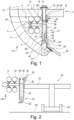
- Fig. 1 shows a structure system 2 for installation to a fuselage structure 6 in an interior of an aircraft.
- the structure system 2 is arranged in a lower deck, which is exemplarily used as a cargo compartment.
- Certain equipment components 4 are provided that are to be installed inside a so-called triangle region 8.
- a crossbeam 10 is provided for supporting a cabin floor of the cabin arranged above the cargo compartment. It is to be understood, that a plurality of crossbeams 10 is arranged along the longitudinal direction, i.e. the x axis, of the fuselage structure 6.
- a seat rail 14 is provided at the top side 12 of the crossbeams 10.
- the seat rail 14 has first attachment devices 16, which carry a first carrier element 18.
- the first carrier element 18 is simply a mechanical interface integrated into or attached to the first attachment device 16. It is to be understood, that a plurality of first attachment devices 16 is arranged and distributed along the longitudinal axis of the fuselage structure 6 as well as a plurality of first carrier elements 18.
- a module frame 21 is arranged, which is realized by an arrangement of elongate frame elements 22 that are distributed parallel and at a distance to each other along the x axis.
- the frame elements 22 each comprise a first end 24 and a second end 26.
- the resulting module frame 21 has a first lateral face 28 and a second lateral face 30, wherein the first ends 24 define a first edge of the module frame 21 and the second ends 26 define a second edge of the module frame 21.
- the first lateral face 28 is dedicated for carrying the equipment components 4.
- component holders 32 are provided. The attachment of the equipment components 4 to the component holders 32 is explained in further detail below.
- the frame elements 22 comprise a first coupling device 34 for coupling the frame elements 22 to the first carrier elements 18.
- a fastening element 36 in combination with a through-hole 38 is provided, wherein the fastening element 36 sticks through the first coupling device 34 and the first attachment device 18 in a horizontal orientation, i.e. parallel to the y axis.
- the fastening element 36 may be a ball lock pin or a bolt.
- an elongate profile component in form of a closing angle 40 is provided for providing a wall termination bar or such, which allows to couple a plurality of elongate frame elements 22 with a predetermined spacing to each other.
- the second lateral face 30 that faces away from the triangle region 8 and into the cargo compartment may function as cargo compartment wall or an attachment base for a cargo compartment wall.
- the lateral faces 28 and 30 extend along the x and z axes and thus, the module frame 21 created through a plurality of elongate frame elements 22 is arranged vertically. While the connection between the first coupling devices 34 and the first carrier elements 18 is provided as a fixed connection, the opposed side at the second ends 26 is designed differently.
- the frame elements 22 comprise a second coupling device 42, which is adapted to snap into a second carrier element 44.
- Each of the second coupling devices 42 furthermore comprises an elongate compensation element 46, which has an inner end 48 and an outer end 50.
- the outer end 50 protrudes out of the respective frame element 22, wherein the inner end 48 remains inside the frame element 22.
- the elongate compensation element 46 can slide in the z-direction, such that the outer end 50 has a variable distance to the second end 26 of the respective frame element 22.
- a first snap connector 52 is provided that is complementary shaped to a second snap connector 54 arranged at the second carrier element 44. After installing the first coupling device 34 at the first carrier element 18, the position of the outer end 50 relative to the second carrier element 44 can be adjusted, such that the first snap connector 52 engages with the second snap connector 54. Then, the respective frame element 22 is fixedly attached to the fuselage structure 6.
- each of the elongate frame elements 22 comprises a first coupling device 34 and a second coupling device 42.
- the distance between the individual frame elements 22 may correspond to the spacing of circumferential frames of the fuselage structure 6.
- fig. 1 shows a cargo compartment floor 56, which is on the right-hand side in the drawing plane.
- a further closing angle 58 is provided that also acts as a wall termination bar for the cargo compartment and for coupling the frame elements 22, respectively.
- the closing angles 40 and 58 may be an integral part of the module frame 21 in the installed state.
- a mounting jig 60 which comprises a carrying frame 62 and several wheels 64 for moving the jig 60 on a floor 66, which may be a temporary floor or a part of the cargo compartment floor 56.
- the module frame 21 in form of several coupled elongate frame elements 22 comprises the holders 32, the first coupling devices 34, the second coupling devices 42 as well as the components 4 attached to the holders 32. Consequently, the module frame 21 is pre-equipped or pre-installed outside the fuselage structure 6 and can be brought into the interior of the fuselage structure 6 for attaching it. This reduces time and effort for the installation directly inside the fuselage structure 6.
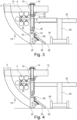
- the module frame 21 After moving the jig 60 together with the pre-equipped module frame 21 into the fuselage structure 6, the module frame 21 is positioned such that the first coupling devices 34 are in a suitable position to be coupled with the first carrier devices 18. This is indicated by an arrow running from the right hand side to the left-hand side in the drawing plane of fig. 3 .
- Fig. 4 shows the connection of the first coupling devices 34 with the first carrier elements 18 by installing the fastening elements 36 in the respective through-holes 38.
- the number of fastening elements 36 depends on the number of first coupling devices 34 and first carrier elements 18. This may of course depend on the extension of the module frame 22 in the x direction.
- first connectors 52 and the second snap connectors 54 are connected to each other. This is done directly after sliding the elongate compensation elements 46 relative to the second ends 26 in a way that both snap connectors 52 and 54 are flush to each other.
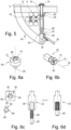
- Figs. 6a and 6b show an exemplary embodiment of the first snap connector 52 and the second snap connector 54.
- the second snap connector 54 comprises an opening 68 for receiving the insert 70 of the first snap connector 52.
- the opening 68 extends in the insertion direction i.e. from top to bottom and in other words from an outer surface 72 into the second snap connector 54.
- the upper part of the opening 68, i.e. at the outer surface 72, may have a cross-sectional shape corresponding to a circumferential outline of the insert 70.
- at least one protrusion 74 may be formed in a direction substantially perpendicular to the inserting direction in the opening 68.
- At least one protrusion 74 of the opening 68 may correspond to a recess 76 formed in the first snap connector 52, as illustrated on the right-hand side in fig. 6a .
- the protrusions 74 are flush with the recesses 76 and when a rotational axis 78 of the first snap connector 52 coincides with a longitudinal axis 80 of the second snap connector 54, the first snap connector 52 can be inserted into the second snap connector 54.
- the first snap connector 52 is rotated about the rotational axis 78, parts of the first snap connector 52 will be held by the protrusions 74.
- three protrusions 74 are symmetrically provided in the second snap connector 54, such that a rotation of about 60° after inserting the first snap connector 52 will clamp the snap connectors 52 and 54 with each other.
- an outer surface 82 of the first snap connector 52 is flushly arranged on the outer surface 72 of the second snap connector 54.
- these surfaces 72 and 82 are spherically curved.
- the elongate compensation element 46 has a cross-sectional surface that is based on a circle and has radial cut-outs 84.
- the number of cut-outs 84 conforms the number of protrusions 74 of the second snap connector 54.
- the cut-outs 84 are evenly distributed in the circumferential direction.
- Sections 86 between the cut-outs 84 comprise first circumferential grooves 88, which corresponded to second circumferential grooves 90 inside the frame element 22.
- the cross-sectional surface has three projections 92, which each comprise the second grooves 90.
- the elongate element 46 can be inserted into an opening 94 of the module frame 22 in a first rotational direction, in which the protrusions 86 are arranged between the projections and 92 of the opening 94.
- the grooves 88 and 90 engage and the longitudinal position of the elongate compensation element 46 is fixed.
- this arrangement constitutes an arresting element 95
- the placement of the projections 92 should be adapted to the placement of the protrusions 74, such that the position of the elongate compensation element 46 can be chosen when inserting the insert 70 into the opening 68.
- a subsequent rotation about 60° leads to locking the two snap connectors 52 and 54 as well as the elongate compensation element 46 in the module frame 22.
- a tolerance compensation is achieved at the same time as a fixation to the second carrier 44 element.
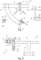
- Fig. 7 shows a further exemplary embodiment of a structure system 96, in which the first carrier element is provided in the form of a rail 98.
- a first coupling device 100a or 100b may be attached to the rail 98.
- the first coupling device 100a is designed as a guide element that comprises two opposed troughs 102, that correspond to guide rollers 104 of the rail 98. Similar to this, the first coupling device 100b is based on cylindrical rollers 106.
- the rail 98 may be attached to the seat rail 14 through the first attachment devices 16 and comprises a suitable interface 108 for this purpose.
- the jig 60 as shown in fig. 8 only needs to provide the pre-installed module frame 21 at a starting point of the rail 98 and the module frame 21 can be moved along the rail 98 into the interior of the fuselage structure 6.
- the module frame 21 is attached to the structure 6 in a similar manner as shown in figs. 3 to 5 .
- the frame elements 22 are temporarily coupled with rails 98, which are used for inserting the frame elements 22 into the structure 6. Afterwards, the rails 98 are removed to provide the fastening steps in analogy to figs. 3 to 5 and 7 to 10 .
- Fig. 15 shows further holders 110 for holding the equipment components 4 in form of lines or ducts.
- individual holders 110 are attached to the frame elements 22.
- Fig. 16 schematically illustrates a flexible bracket 112 to handle variable pipe diameters and to compensate system tolerances.
- Fig. 17a and 17b shows still further holders 114 to provide a snap and click connection for pipes and ducts.
- Fig. 18 shows an aircraft 116 having a fuselage structure 6, into which the above-described installation system is integrated.
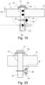
- Fig. 19 shows a modified arrangement of the structure system 2 of fig. 1 .
- the first attachment devices 16 are attached to the crossbeams 10 through a single bolt 118 at the seat rail 14, as well as through fasteners 120, which may be self-piercing rivets.
- the closing angle 40 is attached through the fastening element 36 in the same way as in fig. 1
- the frame element 22 is coupled with the first attachment device 16 through fasteners 120 as well.
- the connection to the first attachment device 16 may be provided in the form of a fork and lug arrangement.
- a removable rail adapter 122 is shown, which is attachable to the closing angle 40 and comprises a rail 98, which extends parallel to the longitudinal axis of the aircraft, into which the frame element 22 is to be installed.
- the removed rail adapter 122 is further shown in Fig. 22 .
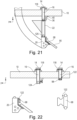
- Fig. 21 shows a connection of the frame element 22 to both the first attachment device 16 and the second carrier element 20 through rotary joints 124, which allow to avoid constraint forces between the structure of the aircraft and the frame element 22.
- fig. 22 shows a further rail adapter 122, which is arrangeable on another first attachment device 16, e.g. at an adjacent seat rail 14, in order to carry a larger rig for moving module frames 21 along the aircraft structure to a desired installation position.
- a rail adapter 122 at another first attachment device 16 also a rail adapter may be placed at the second carrier element 20.
Landscapes
- Engineering & Computer Science (AREA)
- Aviation & Aerospace Engineering (AREA)
- Manufacturing & Machinery (AREA)
- Transportation (AREA)
- Architecture (AREA)
- Civil Engineering (AREA)
- Structural Engineering (AREA)
- Mechanical Engineering (AREA)
- Mutual Connection Of Rods And Tubes (AREA)
Abstract
Description
- The invention relates to a structure system for installation into a fuselage structure in an interior of an aircraft, an installation method as well as an aircraft having at least one such structure system.
- Commercial aircraft with a fuselage structure and a cabin created therein usually comprise a large variety of installation equipment. This may include, besides others, cabin monuments, passenger seats, in-flight entertainment equipment, stowage compartments and so on. Overhead stowage compartments, for example, are often attached to a framework structure in an upper region of the respective cabin. Often, they are brought into the cabin part by part and are installed one after another. Manufacturing-induced dimensional deviations are compensated by suitable adjustment means, such that the stowage compartments create a harmonic and straight appearance.
- However, further types of installation equipment can be found inside the interior of the fuselage that are not visible for a passenger, for example system equipment in an underfloor region, i.e. underneath the cabin, for example in the so-called triangle region. The triangle region is arranged between a cargo compartment and the fuselage structure underneath the cabin floor and may exemplarily comprise a plurality of ducts, pipes, and electrical lines. Often, these components are provided one after another into the aircraft and are attached to structural elements in the triangle region, such as the fuselage structure or lateral delimitation of the cargo compartment. Dedicated holders need to be provided and attached and the system components are coupled with the holders directly inside the fuselage.
- Since the available space is cramped, this part of the installation is cumbersome and time-consuming. Also, providing a plurality of holders for integration into structural elements requires a plurality of different brackets, tools, and other means for an efficient and quick installation.
- It is thus an object of the invention to provide a mounting system or the like for mounting components into an interior structure of an aircraft or an improved method for installing equipment components into the interior structure of the aircraft.
- This object is met by the structure system having the features of independent claim 1. Advantageous embodiments and further improvements may be gathered from the sub claims and the following description.
- A structure system for installation into a fuselage structure in an interior of an aircraft is proposed, the system comprising at least one first carrier element, at least one second carrier element, at least one elongate frame element having a first end and a second end, at least one first attachment device for attaching the first carrier element to the fuselage structure or to an element coupled with the fuselage structure, at least one first coupling device mounted to the first end for coupling the first carrier element to the at least one frame element, and at least one second coupling device mounted to the second end for coupling the second carrier element to the at least one frame element, wherein the at least one frame element is adapted for holding at least one component to be installed in the interior, wherein the at least one first carrier element is designed for coupling with the at least one first coupling device, wherein the at least one second carrier element is designed for coupling with the at least one second coupling device, and wherein one of the at least one first coupling device and the at least one second coupling device is adapted to snap into the respective carrier element, to be moved relative to the respective end of the frame element and to be arrested in a desired relative position thereto.
- A gist of the invention lies in providing a modular structural system that is capable of attaching the respective equipment components to at least one and preferably a plurality of elongate frame elements outside the aircraft to form an assembly, bring the assembly into the aircraft and attach it to the fuselage structure through suitable carrier elements. Here, one of the two carrier elements is capable of providing a simple snap connection that allows to even further simplify the installation process. The assembly is preferably designed to be load carrying to form an integral part of the structure of the aircraft.
- The first carrier element may exemplarily be a mechanical component, which is attached to the fuselage structure with a first attachment device. The elongate frame element is couplable with the first carrier element in the region of the first end. The coupling may comprise a direct or indirect mechanical connection and allows a load transfer in at least one direction and preferably in at least two and in particular in three directions. The design of the first attachment device, the first carrier element and the first coupling device are preferably adapted to optimize the load transfer in this at least one direction. It is conceivable that the elongate frame element, the first carrier element and the first attachment device provide a rotatable coupling of the frame element to the fuselage structure.
- The second carrier element may have a similar or different design. The second carrier element is capable of being coupled with the frame element at the second end. By providing the first carrier element in a distance to the second carrier element, the frame element is coupled to the respective structure over at least two positions, which provides a determined spatial support of the frame element. Again, it is conceivable that the elongate frame element and the second carrier element provide a rotatable coupling of the frame element to the fuselage structure.
- Preferably, a plurality of elongate frame elements are installed in the fuselage structure by a matching number of first carrier elements and second carrier elements. The frame elements may be spaced apart from and aligned parallel to each other. In the installed state, they may create a simple and flat framework, which is herein referred to as module frame, and which is defined by a first edge created by the plurality of first ends and a second edge created by the plurality of second ends, wherein the first edge and the second edge are preferably parallel to each other. Between both edges, two opposite lateral faces are provided. One of or both the lateral faces are intended for holding equipment components. In general, the module frame may provide two sides acting as an interface for installing equipment components.
- The elongate frame element may comprise a cross-sectional surface that provides a sufficient geometrical moment of inertia to be load-carrying and to hold the equipment components. For example, the elongate frame elements may be realized as vertical struts or rods for an inner delimitation of a so-called triangle region of the fuselage structure, which is to be found underneath radial outer regions of a cabin floor between the fuselage skin and a cargo compartment. The first end may comprise the first coupling device, while the second end may comprise the second coupling device. For a pre-installation of the module frame with the equipment components the elongate frame elements may either be connected through a closing angle to remain in the fuselage structure after installation, or the elongate frame elements may temporarily be held in a jig until they are connected to at least one of the carrier elements.
- As indicated above, it is preferred to arrange the frame elements in a vertical manner inside the interior structure, such that the first edge and the second edge of the module frame created by the frame elements extend parallel to the x-axis, while the lateral faces extend parallel to the x-z-plane. The axis definitions refer to an aircraft-fixed coordinate system, wherein the x-axis is the longitudinal axis, the y-axis is the lateral axis and the z-axis is the vertical axis. The first ends may be placed above the second ends. When installed, for example, the frame elements, and thus the module frame, may constitute a lateral delimitation of a cargo compartment. One of the lateral faces then faces into the triangle region and equipment components attached to the respective lateral face are placed inside the triangle region. In this example, the first carrier element may be placed above the second carrier element and may be designed to receive forces in three directions. During installation, first carrier elements may temporarily hold frame elements alone. It may be feasible to move the frame elements with installed equipment components into the interior of the fuselage structure through a mounting jig, attach the first coupling devices to the first carrier elements and remove the jig out of the aircraft. Afterwards, the second coupling devices can be coupled to the second carrier elements. Staying with the example mentioned above, i.e. using several vertically arranged frame elements, all frame elements are subsequently attached to respective first carrier elements, while after removing the jig all second coupling devices are coupled with the respective second carrier elements.
- Due to manufacturing-induced dimensional deviations, it is feasible to let one of the respective coupling devices be variable in length to compensate slight distance deviations between the first and second carrier elements along the extension of the fuselage structure. It is preferred that this length-variable feature is provided in combination with a snap-in connecting element. Thus, after connecting the first coupling devices with the first carrier elements, the frame elements, and thus the module frame, may hang from the first carrier elements downwards and the second coupling devices can be coupled to the second carrier elements while at the same time adjusting their positions relative to the second ends and without requiring the jig.
- Of course, the module frame may be arranged and oriented differently, such as in a horizontal orientation or inclined to a vertical or horizontal plane. It may also be arranged to extend along the y axis at least in a region of the structure. It may comprise different extensions in length, i.e. along the two edges, and width, i.e. in a direction between the edges.
- The structure system according to the invention provides an excellent way of pre-installing equipment components outside the aircraft and reducing required installation time directly inside the interior structure of the aircraft. At the same time, a load-carrying structure may be pre-assembled outside the aircraft and coupled with the fuselage structure in a simple manner.
- In an exemplary embodiment, the second coupling device comprises an elongate compensation element having an outer end, which protrudes away from the at least one elongate frame element, and an inner end, wherein the elongate compensation element is slidably supported in the respective frame element to move the outer end into a variable distance from the second end, and wherein a first snap connector is arranged on the outer end that is complementary shaped to a second snap connector arranged in the at least one second carrier element. Thus, the second coupling device is adapted to snap into the respective carrier element, i.e. the second carrier element. The elongate compensation element may exemplarily be realized in the form of a rod or an auxiliary beam, which preferably has a constant cross-sectional surface that at least partially continuously extends along the main extension direction of the elongate compensation element. It is conceivable that the elongate compensation element is hollow to reduce its weight. For a slidable support, the respective frame element, into which the compensation element is inserted, may comprise a complimentary shaped guide, in which the elongate compensation element can slide freely at least during the installation process. In a simple case, the guide may comprise a hole or a recess. In a modified embodiment explained further below, the guide may include means for arresting the elongate compensation element in a desired position.
- In an advantageous embodiment, the one of the first snap connector and the second snap connector is adapted to receive the other one of the first snap connector and the second snap connector in a first relative rotational position and to hold it in at least one second relative rotational position that is distinct from the first relative rotational position. The first snap connector and the second snap connector are rotatable relative to each other. It is conceivable, that the first snap connector and the second snap connector comprise complimentary shaped insertion and receiving surfaces. For example, one of the snap connectors comprises an insertion body, which is insertable into a recess of the other snap connector. The shapes of both snap connectors are designed in such a way, that an insertion is only possible in one or only a few distinct first relative rotational positions. By rotating the snap connectors relative to each other, second relative rotational positions are reached. In these, the insert is held inside the recess through an engagement of the insertion body and the recess. For example, the recess comprises at least one undercut, into which a lateral protrusion of the insert can be brought. Hence, both snap connectors are secured to each other in the respective second relative rotational positions.
- It is further conceivable that the first snap connector and the second snap connector can be secured with each other, such that an inadvertent rotation can be prevented. This is advantageous to avoid a loosening due to flight-induced vibrations.
- In an advantageous embodiment, the second coupling device comprises an arresting element capable of arresting the elongate compensation element relative to the second end. Thus, a desired position of the elongate compensation element relative to the second edge, i.e. the second ends, can be secured. The tolerance compensation remains adjusted.
- In an advantageous embodiment, the arresting element is integrated into the elongate compensation element. For example, the elongate compensation element may comprise lateral protrusions that engage with lateral recesses in a guide for guiding the elongate compensation element relative to the second end. By rotating the elongate compensation element it may mechanically engage with the guide to maintain its momentary position. Hence, in particular following above example with the first snap connector and the second snap connector, the elongate compensation element is arrested directly after providing a connection between the first snap connector and the second snap connector.
- In an advantageous embodiment one of the first carrier element and the second carrier element comprises at least one rail, wherein the respective coupling device is adapted for being slidably supported by the at least one rail to move the elongate frame element to the respective carrier element. The at least one rail allows to insert pre-equipped frame elements into the respective rail and move it to the desired installation location without requiring a mounting jig.
- In an advantageous embodiment, the respective coupling device and the respective carrier element are connectable independent from the rail, wherein the at least one rail is removable from the respective carrier element after connecting the respective coupling device and the respective carrier element. Thus, the respective rail that further simplifies the installation is no longer required when the frame elements are installed. Removing the respective rail leads to a reduction of weight.
- In an advantageous embodiment a plurality of consecutive frame elements are connectable through at least one profile component that extends along a plurality of first ends or a plurality of second ends. The plurality of frame elements may then be coupled with one or more respective profile component(s) to create a module frame.
- In an advantageous embodiment the first attachment device is connectable to or integratable into a cabin seat rail at a bottom side, such that the at least one frame element is placeable underneath and is couplable with the seat rail. The seat rail is usually connected to a plurality of crossbeams in the interior structure of the aircraft and creates a sturdy base for the installation of the frame element(s). By simply combining the first attachment devices with the seat rail, particularly frame elements dedicated for providing a triangle region structure can be attached.
- In an advantageous embodiment at least one of the first coupling device and the second coupling device comprises a fastening element that is adapted to be sticked through the at least one frame element and the respective coupling device. The attachment of the at least one frame element is simple and does not require drilling, screwing and use of tools. For example, the fastening element may latch after insertion, such that a simple insertion motion is sufficient. For example, a fastening element may be provided in the form of a ball lock pin.
- The invention further relates to a method for mounting structural and equipment components to a fuselage structure in an interior of an aircraft, comprising the steps of providing at least one frame element having a first end, and a second end, attaching at least one component on the at least one frame element, moving the at least one frame element into the fuselage structure, coupling at least one first coupling device mounted to the first end to a first carrier element attached to the fuselage structure through at least one first attachment device, and coupling at least one second coupling device mounted to the second end to a second carrier element attached to the fuselage structure, wherein the coupling of one of the at least one first coupling device and the at least one second coupling device includes a snapping into the respective module carrier, to be moved relative to the respective end of the at least one frame element and to be arrested in a desired relative position thereto.
- In an advantageous embodiment, the method further comprises sliding an elongate compensation element at the second coupling device, which elongate compensation element having an outer end protruding away from the respective frame element and an inner end, to move an outer end into a distance from the second end, such that a first snap connector arranged on the outer end reaches a complementary shaped second snap connector arranged in the at least one second carrier element, and snapping the first snap connector into the second snap connector.
- The invention further relates to a vehicle, comprising a structure, at least one component and at least one structure system according to the above description for installation into a fuselage structure.
- In an advantageous embodiment, the at least one component, which is held by the at least one frame element of the structure system, comprises a fluid pipe, a duct, or an electric line.
- In an advantageous embodiment, the vehicle is an aircraft, wherein the structure system is adapted to arrange the at least one component in a triangle region of the aircraft.
- In the following, the attached drawings are used to illustrate exemplary embodiments in more detail. The illustrations are schematic and not to scale. Identical reference numerals refer to identical or similar elements. They show:
-
Fig. 1 shows a section view of a structure system in an interior structure of an aircraft. -
Fig. 2 shows a jig carrying a pre-equipped module frame. -
Fig. 3 shows the jig ofFig. 2 being placed inside the interior structure. -
Fig. 4 shows first coupling devices being coupled with first module carriers. -
Fig. 5 shows second coupling devices being coupled with second module carriers. -
Fig. 6a and 6b show a first and a second snap connector. -
Fig. 6c and 6d show an elongate element with integrated arresting element in the module frame. -
Fig. 7 shows a structure system using a rail. -
Fig. 8 shows pre-equipment of a module frame with a rail. -
Fig. 9 shows insertion of the pre-equipped module frame into the structure through a jig. -
Fig. 10 shows the coupling of the first coupling devices with the first module carrier. -
Fig. 11 shows insertion of a small jig into the structure with several rails being arranged between consecutive module frame components. -
Fig. 12 shows the fastening of the module frame. -
Fig. 13 shows the rails being removed. -
Fig. 14 shows the second snap connector being moved and connected. -
Fig. 15 shows holders for holding equipment components. -
Fig. 16 shows flexible brackets for holding different equipment components. -
Fig. 17 shows further examples of brackets. -
Fig. 18 shows an aircraft. -
Fig. 19 to 22 show a modified attachment of a module frame. -
Fig. 1 shows astructure system 2 for installation to afuselage structure 6 in an interior of an aircraft. Here, exemplarily thestructure system 2 is arranged in a lower deck, which is exemplarily used as a cargo compartment.Certain equipment components 4 are provided that are to be installed inside a so-calledtriangle region 8. At an upper side in the drawing plane, acrossbeam 10 is provided for supporting a cabin floor of the cabin arranged above the cargo compartment. It is to be understood, that a plurality ofcrossbeams 10 is arranged along the longitudinal direction, i.e. the x axis, of thefuselage structure 6. At thetop side 12 of thecrossbeams 10, aseat rail 14 is provided. - In this exemplary embodiment, the
seat rail 14 hasfirst attachment devices 16, which carry afirst carrier element 18. In this case, thefirst carrier element 18 is simply a mechanical interface integrated into or attached to thefirst attachment device 16. It is to be understood, that a plurality offirst attachment devices 16 is arranged and distributed along the longitudinal axis of thefuselage structure 6 as well as a plurality offirst carrier elements 18. - Opposed to the
first carrier elements 18,second carrier elements 20 are provided attached to thefuselage structure 6. Between thefirst carrier elements 18 and thesecond carrier elements 20, amodule frame 21 is arranged, which is realized by an arrangement ofelongate frame elements 22 that are distributed parallel and at a distance to each other along the x axis. Theframe elements 22 each comprise afirst end 24 and asecond end 26. The resultingmodule frame 21 has a firstlateral face 28 and a secondlateral face 30, wherein the first ends 24 define a first edge of themodule frame 21 and the second ends 26 define a second edge of themodule frame 21. In this exemplary embodiment, the firstlateral face 28 is dedicated for carrying theequipment components 4. For this,component holders 32 are provided. The attachment of theequipment components 4 to thecomponent holders 32 is explained in further detail below. - The
frame elements 22 comprise afirst coupling device 34 for coupling theframe elements 22 to thefirst carrier elements 18. Here, afastening element 36 in combination with a through-hole 38 is provided, wherein thefastening element 36 sticks through thefirst coupling device 34 and thefirst attachment device 18 in a horizontal orientation, i.e. parallel to the y axis. For example, thefastening element 36 may be a ball lock pin or a bolt. In addition, an elongate profile component in form of aclosing angle 40 is provided for providing a wall termination bar or such, which allows to couple a plurality ofelongate frame elements 22 with a predetermined spacing to each other. The secondlateral face 30 that faces away from thetriangle region 8 and into the cargo compartment may function as cargo compartment wall or an attachment base for a cargo compartment wall. As apparent fromfig. 1 , the lateral faces 28 and 30 extend along the x and z axes and thus, themodule frame 21 created through a plurality ofelongate frame elements 22 is arranged vertically. While the connection between thefirst coupling devices 34 and thefirst carrier elements 18 is provided as a fixed connection, the opposed side at the second ends 26 is designed differently. - Here, the
frame elements 22 comprise asecond coupling device 42, which is adapted to snap into asecond carrier element 44. Each of thesecond coupling devices 42 furthermore comprises anelongate compensation element 46, which has aninner end 48 and anouter end 50. Theouter end 50 protrudes out of therespective frame element 22, wherein theinner end 48 remains inside theframe element 22. Theelongate compensation element 46 can slide in the z-direction, such that theouter end 50 has a variable distance to thesecond end 26 of therespective frame element 22. - At the
outer end 50, afirst snap connector 52 is provided that is complementary shaped to asecond snap connector 54 arranged at thesecond carrier element 44. After installing thefirst coupling device 34 at thefirst carrier element 18, the position of theouter end 50 relative to thesecond carrier element 44 can be adjusted, such that thefirst snap connector 52 engages with thesecond snap connector 54. Then, therespective frame element 22 is fixedly attached to thefuselage structure 6. - As stated above, it is conceivable that each of the
elongate frame elements 22 comprises afirst coupling device 34 and asecond coupling device 42. The distance between theindividual frame elements 22 may correspond to the spacing of circumferential frames of thefuselage structure 6. - Furthermore,
fig. 1 shows acargo compartment floor 56, which is on the right-hand side in the drawing plane. Here, afurther closing angle 58 is provided that also acts as a wall termination bar for the cargo compartment and for coupling theframe elements 22, respectively. The closing angles 40 and 58 may be an integral part of themodule frame 21 in the installed state. - In
fig. 2 , a mountingjig 60 is shown, which comprises a carryingframe 62 andseveral wheels 64 for moving thejig 60 on afloor 66, which may be a temporary floor or a part of thecargo compartment floor 56. Here, themodule frame 21 in form of several coupledelongate frame elements 22 comprises theholders 32, thefirst coupling devices 34, thesecond coupling devices 42 as well as thecomponents 4 attached to theholders 32. Consequently, themodule frame 21 is pre-equipped or pre-installed outside thefuselage structure 6 and can be brought into the interior of thefuselage structure 6 for attaching it. This reduces time and effort for the installation directly inside thefuselage structure 6. - After moving the
jig 60 together with thepre-equipped module frame 21 into thefuselage structure 6, themodule frame 21 is positioned such that thefirst coupling devices 34 are in a suitable position to be coupled with thefirst carrier devices 18. This is indicated by an arrow running from the right hand side to the left-hand side in the drawing plane offig. 3 . -
Fig. 4 shows the connection of thefirst coupling devices 34 with thefirst carrier elements 18 by installing thefastening elements 36 in the respective through-holes 38. The number offastening elements 36 depends on the number offirst coupling devices 34 andfirst carrier elements 18. This may of course depend on the extension of themodule frame 22 in the x direction. - Afterwards, as shown in
figure 5 , thefirst connectors 52 and thesecond snap connectors 54 are connected to each other. This is done directly after sliding theelongate compensation elements 46 relative to the second ends 26 in a way that both snapconnectors -
Figs. 6a and 6b show an exemplary embodiment of thefirst snap connector 52 and thesecond snap connector 54. Thesecond snap connector 54 comprises anopening 68 for receiving theinsert 70 of thefirst snap connector 52. Theopening 68 extends in the insertion direction i.e. from top to bottom and in other words from anouter surface 72 into thesecond snap connector 54. The upper part of theopening 68, i.e. at theouter surface 72, may have a cross-sectional shape corresponding to a circumferential outline of theinsert 70. For example, at least oneprotrusion 74 may be formed in a direction substantially perpendicular to the inserting direction in theopening 68. At least oneprotrusion 74 of theopening 68 may correspond to arecess 76 formed in thefirst snap connector 52, as illustrated on the right-hand side infig. 6a . When theprotrusions 74 are flush with therecesses 76 and when arotational axis 78 of thefirst snap connector 52 coincides with alongitudinal axis 80 of thesecond snap connector 54, thefirst snap connector 52 can be inserted into thesecond snap connector 54. When thefirst snap connector 52 is rotated about therotational axis 78, parts of thefirst snap connector 52 will be held by theprotrusions 74. In this example, threeprotrusions 74 are symmetrically provided in thesecond snap connector 54, such that a rotation of about 60° after inserting thefirst snap connector 52 will clamp thesnap connectors outer surface 82 of thefirst snap connector 52 is flushly arranged on theouter surface 72 of thesecond snap connector 54. Exemplarily, thesesurfaces - In
figs. 6c and 6d , an exemplary embodiment of theelongate compensation element 46 and its connection to theframe elements 22 is shown. Here, theelongate compensation element 46 has a cross-sectional surface that is based on a circle and has radial cut-outs 84. Here, the number of cut-outs 84 conforms the number ofprotrusions 74 of thesecond snap connector 54. The cut-outs 84 are evenly distributed in the circumferential direction.Sections 86 between the cut-outs 84 comprise firstcircumferential grooves 88, which corresponded to secondcircumferential grooves 90 inside theframe element 22. Here, the cross-sectional surface has threeprojections 92, which each comprise thesecond grooves 90. Thus, theelongate element 46 can be inserted into anopening 94 of themodule frame 22 in a first rotational direction, in which theprotrusions 86 are arranged between the projections and 92 of theopening 94. By rotating theelongate compensation element 46, thegrooves elongate compensation element 46 is fixed. Thus, this arrangement constitutes an arrestingelement 95 The placement of theprojections 92 should be adapted to the placement of theprotrusions 74, such that the position of theelongate compensation element 46 can be chosen when inserting theinsert 70 into theopening 68. A subsequent rotation about 60° leads to locking the twosnap connectors elongate compensation element 46 in themodule frame 22. Thus, a tolerance compensation is achieved at the same time as a fixation to thesecond carrier 44 element. -
Fig. 7 shows a further exemplary embodiment of astructure system 96, in which the first carrier element is provided in the form of arail 98. Afirst coupling device rail 98. Thefirst coupling device 100a is designed as a guide element that comprises twoopposed troughs 102, that correspond to guiderollers 104 of therail 98. Similar to this, thefirst coupling device 100b is based oncylindrical rollers 106. Therail 98 may be attached to theseat rail 14 through thefirst attachment devices 16 and comprises asuitable interface 108 for this purpose. - The
jig 60 as shown infig. 8 only needs to provide thepre-installed module frame 21 at a starting point of therail 98 and themodule frame 21 can be moved along therail 98 into the interior of thefuselage structure 6. - Afterwards, as shown in
figs. 9 and 10 , themodule frame 21 is attached to thestructure 6 in a similar manner as shown infigs. 3 to 5 . - As shown in
figs. 11 to 14 , theframe elements 22 are temporarily coupled withrails 98, which are used for inserting theframe elements 22 into thestructure 6. Afterwards, therails 98 are removed to provide the fastening steps in analogy tofigs. 3 to 5 and7 to 10 . -
Fig. 15 showsfurther holders 110 for holding theequipment components 4 in form of lines or ducts. Here,individual holders 110 are attached to theframe elements 22.Fig. 16 schematically illustrates aflexible bracket 112 to handle variable pipe diameters and to compensate system tolerances.Fig. 17a and 17b shows stillfurther holders 114 to provide a snap and click connection for pipes and ducts. -
Fig. 18 shows anaircraft 116 having afuselage structure 6, into which the above-described installation system is integrated. -
Fig. 19 shows a modified arrangement of thestructure system 2 offig. 1 . Here, thefirst attachment devices 16 are attached to thecrossbeams 10 through asingle bolt 118 at theseat rail 14, as well as throughfasteners 120, which may be self-piercing rivets. While the closingangle 40 is attached through thefastening element 36 in the same way as infig. 1 , theframe element 22 is coupled with thefirst attachment device 16 throughfasteners 120 as well. Here, the connection to thefirst attachment device 16 may be provided in the form of a fork and lug arrangement. - In
fig. 20 , aremovable rail adapter 122 is shown, which is attachable to theclosing angle 40 and comprises arail 98, which extends parallel to the longitudinal axis of the aircraft, into which theframe element 22 is to be installed. The removedrail adapter 122 is further shown inFig. 22 . -
Fig. 21 shows a connection of theframe element 22 to both thefirst attachment device 16 and thesecond carrier element 20 throughrotary joints 124, which allow to avoid constraint forces between the structure of the aircraft and theframe element 22. - Lastly,
fig. 22 shows afurther rail adapter 122, which is arrangeable on anotherfirst attachment device 16, e.g. at anadjacent seat rail 14, in order to carry a larger rig for moving module frames 21 along the aircraft structure to a desired installation position. Instead of arail adapter 122 at anotherfirst attachment device 16, also a rail adapter may be placed at thesecond carrier element 20. -
- 2
- structure system
- 4
- equipment component
- 6
- fuselage structure
- 8
- triangle region
- 10
- crossbeam
- 12
- topside
- 14
- seat rail
- 16
- first attachment device
- 18
- first module carrier
- 20
- second module carrier
- 21
- module frame
- 22
- elongate frame element
- 24
- first end
- 26
- second edge
- 28
- first lateral side
- 30
- second lateral side
- 32
- component holder
- 34
- first coupling device
- 36
- fastening element
- 38
- through-hole
- 40
- closing angle
- 42
- second coupling device
- 44
- second module carrier
- 46
- elongate compensation element
- 48
- inner end
- 50
- outer end
- 52
- first snap connector
- 54
- second snap connector
- 56
- cargo compartment floor
- 58
- closing angle
- 60
- mounting jig
- 62
- carrying frame
- 64
- wheel
- 66
- floor
- 68
- opening
- 70
- insert
- 72
- outer surface
- 74
- protrusion
- 76
- recess
- 78
- rotational axis
- 80
- longitudinal axis
- 82
- outer surface
- 84
- radial cutout
- 86
- section
- 88
- first circumferential groove
- 90
- second circumferential groove
- 92
- projection
- 94
- opening
- 95
- arresting element
- 96
- structure system
- 98
- rail
- 100a, 100b
- first coupling device
- 102
- trough
- 104
- guide roller
- 106
- cylindrical roller
- 108
- interface
- 110
- holder
- 112
- flexible bracket
- 114
- holder
- 116
- aircraft
- 118
- bolt
- 120
- fastener
- 122
- rail adapter
- 124
- rotary joint
Claims (15)
- Structure system (2, 96) for installation into a fuselage structure (6) in an interior of an aircraft (116), comprising:at least one first carrier element (18),at least one second carrier element (20, 44),at least one elongate frame element (22) having a first end (24) and a second end (26),at least one first attachment device (16) for attaching the first carrier element (18) to the fuselage structure (6) or to an element coupled with the fuselage structure (6),at least one first coupling device (34, 100) mounted to the first end (24) for coupling the first carrier element (18) to the at least one frame element (22), andat least one second coupling device (42) mounted to the second end (26) for coupling the second carrier element (20, 44) to the at least one frame element (22),wherein the at least one frame element (22) is adapted for holding at least one component (4) to be installed in the interior,wherein the at least one first carrier element (18) is designed for coupling with the at least one first coupling device (34, 100),wherein the at least one second carrier element (20, 44) is designed for coupling with the at least one second coupling device (42), andwherein one of the at least one first coupling device (34, 100) and the at least one second coupling device (42) is adapted to snap into the respective carrier element (18, 20, 44), to be moved relative to the respective end of the frame element (22) and to be arrested in a desired relative position thereto.
- Structure system (2, 96) of claim 1,wherein the second coupling device (42) comprises an elongate compensation element (46) having an outer end (50), which protrudes away from the at least one elongate frame element (22), and an inner end (48),wherein the elongate compensation element (46) is slidably supported in the respective frame element (22) to move the outer end (50) into a variable distance from the second end (26), andwherein a first snap connector (52) is arranged on the outer end (50) that is complementary shaped to a second snap connector (54) arranged in the at least one second carrier element (20, 44).
- Structure system (2, 96) of claim 2,
wherein the one of the first snap connector (52) and the second snap connector (54) is adapted to receive the other one of the first snap connector (52) and the second snap connector (54) in a first relative rotational position and to hold it in at least one second relative rotational position that is distinct from the first relative rotational position. - Structure system (2, 96) of claim 2 or 3,
wherein the second coupling device (42) comprises an arresting element (95) capable of arresting the elongate compensation element (46) relative to the second end (26). - Structure system (2, 96) of claim 4,
wherein the arresting element (95) is integrated into the elongate compensation element (46). - Structure system (2, 96) of any of the preceding claims,Wherein one of the first carrier element (18) and the second carrier element (20, 44) comprises at least one rail (98), andwherein the respective coupling device (34, 42, 100) is adapted for being slidably supported by the at least one rail (98) to move the at least one elongate frame element (22) to the respective carrier element (18, 20, 44).
- Structure system (2, 96) of claim 6,wherein the respective coupling device (34, 42, 100) and the respective carrier element (18, 20, 44) are connectable independent from the rail (98), andwherein the at least one rail (98) is removable from the respective carrier element (18, 20, 44) after connecting the respective coupling device (34, 42, 100) and the respective carrier element (18, 20, 44).
- Structure system (2, 96) of any of the preceding claims,
wherein a plurality of consecutive frame elements (22) are connectable through at least one profile component (40) that extends along a plurality of first ends (24) or a plurality of second ends (26). - Structure system (2, 96) of any of the preceding claims,
wherein the first attachment device (16) is connectable to or integratable into a cabin seat rail (14) at a bottom side, such that the at least one frame element (22) is placeable underneath and is couplable with the seat rail (14). - Structure system (2, 96) of any of the preceding claims,
wherein at least one of the first coupling device (34, 100) and the second coupling device (42) comprises a fastening element (36) that is adapted to be sticked through the at least one frame element (22) and the respective coupling device (34, 42, 100). - Method for mounting structural and equipment components (4) to a fuselage structure in an interior of an aircraft (116), comprising the steps:providing at least one frame element (22) having a first end (24) and a second end (26),attaching at least one component (4) on the at least one frame element (22),moving the at least one frame element (22) into the fuselage structure (6),coupling at least one first coupling device (34, 100) mounted to the first end (24) to a first carrier element (18) attached to the fuselage structure (6) through at least one first attachment device (16), andcoupling at least one second coupling device (42) mounted to the second end (26) to a second carrier element (20, 44) attached to the fuselage structure (6),wherein the coupling of one of the at least one first coupling device (34, 100) and the at least one second coupling device (42) includes a snapping into the respective carrier element (18, 20, 44), to be moved relative to the respective end (24, 26) of the frame element (22) and to be arrested in a desired relative position thereto.
- Method according to claim 11, further comprisingsliding an elongate compensation element (46) at the second coupling device (42), which elongate compensation element (46) having an outer end (50) protruding away from the respective frame element (22) and an inner end (48), to move an outer end (50) into a distance from the second end (26), such that a first snap connector (52) arranged on the outer end (50) reaches a complementary shaped second snap connector (54) arranged in the at least one second carrier element (20, 44), andsnapping the first snap connector (52) into the second snap connector (54).
- Vehicle (116), comprising a fuselage structure (6), at least one component (4) and at least one structure system (2, 96) according to any of the claims 1 to 10 for attaching the at least one component (4) to the fuselage structure (6).
- Vehicle (116) according to claim 13,
wherein the at least one component (4) comprises a fluid pipe, a duct, or an electric line. - Vehicle (!16) according to claim 13 or 14,wherein the vehicle is an aircraft (116), andwherein the structure system (2, 96) is adapted to arrange the at least one component (4) in a triangle region of the aircraft (116).
Priority Applications (3)
| Application Number | Priority Date | Filing Date | Title |
|---|---|---|---|
| EP22214474.3A EP4389593B1 (en) | 2022-12-19 | 2022-12-19 | Structure system for installation into a fuselage structure |
| CN202311718679.3A CN118220464A (en) | 2022-12-19 | 2023-12-14 | Structural system installed into the fuselage structure |
| US18/545,303 US20240199235A1 (en) | 2022-12-19 | 2023-12-19 | Structure system for installation into a fuselage structure |
Applications Claiming Priority (1)
| Application Number | Priority Date | Filing Date | Title |
|---|---|---|---|
| EP22214474.3A EP4389593B1 (en) | 2022-12-19 | 2022-12-19 | Structure system for installation into a fuselage structure |
Publications (2)
| Publication Number | Publication Date |
|---|---|
| EP4389593A1 true EP4389593A1 (en) | 2024-06-26 |
| EP4389593B1 EP4389593B1 (en) | 2026-05-13 |
Family
ID=84538046
Family Applications (1)
| Application Number | Title | Priority Date | Filing Date |
|---|---|---|---|
| EP22214474.3A Active EP4389593B1 (en) | 2022-12-19 | 2022-12-19 | Structure system for installation into a fuselage structure |
Country Status (3)
| Country | Link |
|---|---|
| US (1) | US20240199235A1 (en) |
| EP (1) | EP4389593B1 (en) |
| CN (1) | CN118220464A (en) |
Citations (6)
| Publication number | Priority date | Publication date | Assignee | Title |
|---|---|---|---|---|
| US20050224677A1 (en) * | 2004-03-08 | 2005-10-13 | Airbus Deutschland Gmbh | Holder for holding and guiding bundles of cables in aircraft |
| US8770532B2 (en) * | 2011-05-13 | 2014-07-08 | Commscope, Inc. Of North Carolina | Cable retaining ring having slide closure and cable support tray including the cable retaining ring |
| US9077167B2 (en) * | 2010-02-16 | 2015-07-07 | Airbus Operations Limited | Aircraft raceway mounting and clamping apparatus |
| US20190127038A1 (en) * | 2017-10-27 | 2019-05-02 | Airbus Operations Gmbh | Aircraft framework assembly, aircraft structural framework and aircraft with an aircraft structural framework |
| US20200056726A1 (en) * | 2018-08-20 | 2020-02-20 | Spirit Aerosystems, Inc. | Multi-function system support tray |
| US20210188417A1 (en) * | 2019-12-18 | 2021-06-24 | Airbus Operations Sas | Aircraft fuselage portion comprising movable or detachable under floor struts |
-
2022
- 2022-12-19 EP EP22214474.3A patent/EP4389593B1/en active Active
-
2023
- 2023-12-14 CN CN202311718679.3A patent/CN118220464A/en active Pending
- 2023-12-19 US US18/545,303 patent/US20240199235A1/en active Pending
Patent Citations (6)
| Publication number | Priority date | Publication date | Assignee | Title |
|---|---|---|---|---|
| US20050224677A1 (en) * | 2004-03-08 | 2005-10-13 | Airbus Deutschland Gmbh | Holder for holding and guiding bundles of cables in aircraft |
| US9077167B2 (en) * | 2010-02-16 | 2015-07-07 | Airbus Operations Limited | Aircraft raceway mounting and clamping apparatus |
| US8770532B2 (en) * | 2011-05-13 | 2014-07-08 | Commscope, Inc. Of North Carolina | Cable retaining ring having slide closure and cable support tray including the cable retaining ring |
| US20190127038A1 (en) * | 2017-10-27 | 2019-05-02 | Airbus Operations Gmbh | Aircraft framework assembly, aircraft structural framework and aircraft with an aircraft structural framework |
| US20200056726A1 (en) * | 2018-08-20 | 2020-02-20 | Spirit Aerosystems, Inc. | Multi-function system support tray |
| US20210188417A1 (en) * | 2019-12-18 | 2021-06-24 | Airbus Operations Sas | Aircraft fuselage portion comprising movable or detachable under floor struts |
Also Published As
| Publication number | Publication date |
|---|---|
| US20240199235A1 (en) | 2024-06-20 |
| EP4389593B1 (en) | 2026-05-13 |
| CN118220464A (en) | 2024-06-21 |
Similar Documents
| Publication | Publication Date | Title |
|---|---|---|
| CN110015397B (en) | Fixing system and aircraft | |
| CN101506043B (en) | Frame element, storage bin and method for installing a storage bin in an aircraft | |
| US8474758B2 (en) | Aircraft component assembly system | |
| EP2853495B1 (en) | Method for the assembly of an aircraft fuselage and fuselage manufacturing station | |
| US8534603B2 (en) | System and method for manufacturing a vehicle cabin | |
| CN105579286B (en) | For front-end module and headlight to be mounted on to the holding system of method and headlight on front-end module on coachbuilt body | |
| US11541981B2 (en) | Method for installing system components in a portion of an aircraft fuselage | |
| JP2011502859A (en) | Aircraft fuselage cell structure for simplified installation and attachment of fasteners for securing pipes | |
| EP3153407A1 (en) | Adjustable support structure for aircraft cabin ceiling | |
| EP3266705A1 (en) | Interior component carrier system and method for mounting an aircraft interior component carrier system | |
| CN110626520A (en) | Aircraft module, aircraft section, aircraft and aircraft section assembly method | |
| CA3028049A1 (en) | A quick-fastening support device for supporting elements that are to be routed on an associated structure | |
| EP3135585A1 (en) | Crown raceway support (crs) for crown integration panel (cip) | |
| US20190193872A1 (en) | Modular System For Installing Modules On A Fuselage Structure Of A Vehicle | |
| US20210300560A1 (en) | Fastening apparatus and fastening arrangement for fastening a cabin interior component, aircraft cabin and aircraft | |
| EP4389593B1 (en) | Structure system for installation into a fuselage structure | |
| CN111252231A (en) | Connecting part, aircraft mechanical assembly and module with connecting part and aircraft | |
| US20230249830A1 (en) | Carrier device, seating area divider and vehicle cabin | |
| US8070097B2 (en) | Mobile divider for an aircraft | |
| EP4316984A1 (en) | Fastening structure for a monument and an overhead storage bin and vehicle | |
| US20240190586A1 (en) | Assembly system and method for assembling aircraft system components in the triangle region | |
| EP4201813B1 (en) | Method for installing a fastening structure for at least one component on an attachment structure of a vehicle interior and jig for positioning a fastening structure | |
| EP4647615A1 (en) | Tolerance compensator and installation system | |
| EP4692581A1 (en) | Coupling system, fastening structure and vehicle | |
| EP4112443B1 (en) | Structural system for an aircraft for installation of equipment |
Legal Events
| Date | Code | Title | Description |
|---|---|---|---|
| PUAI | Public reference made under article 153(3) epc to a published international application that has entered the european phase |
Free format text: ORIGINAL CODE: 0009012 |
|
| STAA | Information on the status of an ep patent application or granted ep patent |
Free format text: STATUS: THE APPLICATION HAS BEEN PUBLISHED |
|
| AK | Designated contracting states |
Kind code of ref document: A1 Designated state(s): AL AT BE BG CH CY CZ DE DK EE ES FI FR GB GR HR HU IE IS IT LI LT LU LV MC ME MK MT NL NO PL PT RO RS SE SI SK SM TR |
|
| STAA | Information on the status of an ep patent application or granted ep patent |
Free format text: STATUS: REQUEST FOR EXAMINATION WAS MADE |
|
| 17P | Request for examination filed |
Effective date: 20241223 |
|
| GRAP | Despatch of communication of intention to grant a patent |
Free format text: ORIGINAL CODE: EPIDOSNIGR1 |
|
| STAA | Information on the status of an ep patent application or granted ep patent |
Free format text: STATUS: GRANT OF PATENT IS INTENDED |
|
| INTG | Intention to grant announced |
Effective date: 20251117 |
|
| GRAJ | Information related to disapproval of communication of intention to grant by the applicant or resumption of examination proceedings by the epo deleted |
Free format text: ORIGINAL CODE: EPIDOSDIGR1 |
|
| STAA | Information on the status of an ep patent application or granted ep patent |
Free format text: STATUS: REQUEST FOR EXAMINATION WAS MADE |
|
| GRAP | Despatch of communication of intention to grant a patent |
Free format text: ORIGINAL CODE: EPIDOSNIGR1 |
|
| STAA | Information on the status of an ep patent application or granted ep patent |
Free format text: STATUS: GRANT OF PATENT IS INTENDED |
|
| INTC | Intention to grant announced (deleted) | ||
| GRAS | Grant fee paid |
Free format text: ORIGINAL CODE: EPIDOSNIGR3 |
|
| INTG | Intention to grant announced |
Effective date: 20260302 |
|
| GRAA | (expected) grant |
Free format text: ORIGINAL CODE: 0009210 |
|
| STAA | Information on the status of an ep patent application or granted ep patent |
Free format text: STATUS: THE PATENT HAS BEEN GRANTED |
|
| AK | Designated contracting states |
Kind code of ref document: B1 Designated state(s): AL AT BE BG CH CY CZ DE DK EE ES FI FR GB GR HR HU IE IS IT LI LT LU LV MC ME MK MT NL NO PL PT RO RS SE SI SK SM TR |
|
| REG | Reference to a national code |
Ref country code: CH Ref legal event code: F10 Free format text: ST27 STATUS EVENT CODE: U-0-0-F10-F00 (AS PROVIDED BY THE NATIONAL OFFICE) Effective date: 20260513 |