EP4389591A1 - Hatch locking device, air- or spacecraft hatch and air- or spacecraft - Google Patents
Hatch locking device, air- or spacecraft hatch and air- or spacecraft Download PDFInfo
- Publication number
- EP4389591A1 EP4389591A1 EP22214514.6A EP22214514A EP4389591A1 EP 4389591 A1 EP4389591 A1 EP 4389591A1 EP 22214514 A EP22214514 A EP 22214514A EP 4389591 A1 EP4389591 A1 EP 4389591A1
- Authority
- EP
- European Patent Office
- Prior art keywords
- hatch
- locking
- spacecraft
- bush
- eccentric bush
- Prior art date
- Legal status (The legal status is an assumption and is not a legal conclusion. Google has not performed a legal analysis and makes no representation as to the accuracy of the status listed.)
- Granted
Links
Images

Classifications
-
- E—FIXED CONSTRUCTIONS
- E05—LOCKS; KEYS; WINDOW OR DOOR FITTINGS; SAFES
- E05C—BOLTS OR FASTENING DEVICES FOR WINGS, SPECIALLY FOR DOORS OR WINDOWS
- E05C9/00—Arrangements of simultaneously actuated bolts or other securing devices at well-separated positions on the same wing
- E05C9/22—Guides for sliding bars, rods or cables
-
- E—FIXED CONSTRUCTIONS
- E05—LOCKS; KEYS; WINDOW OR DOOR FITTINGS; SAFES
- E05B—LOCKS; ACCESSORIES THEREFOR; HANDCUFFS
- E05B65/00—Locks or fastenings for special use
-
- B—PERFORMING OPERATIONS; TRANSPORTING
- B64—AIRCRAFT; AVIATION; COSMONAUTICS
- B64C—AEROPLANES; HELICOPTERS
- B64C1/00—Fuselages; Constructional features common to fuselages, wings, stabilising surfaces or the like
- B64C1/14—Windows; Doors; Hatch covers or access panels; Surrounding frame structures; Canopies; Windscreens accessories therefor, e.g. pressure sensors, water deflectors, hinges, seals, handles, latches, windscreen wipers
-
- E—FIXED CONSTRUCTIONS
- E05—LOCKS; KEYS; WINDOW OR DOOR FITTINGS; SAFES
- E05B—LOCKS; ACCESSORIES THEREFOR; HANDCUFFS
- E05B15/00—Other details of locks; Parts for engagement by bolts of fastening devices
-
- E—FIXED CONSTRUCTIONS
- E05—LOCKS; KEYS; WINDOW OR DOOR FITTINGS; SAFES
- E05B—LOCKS; ACCESSORIES THEREFOR; HANDCUFFS
- E05B17/00—Accessories in connection with locks
-
- E—FIXED CONSTRUCTIONS
- E05—LOCKS; KEYS; WINDOW OR DOOR FITTINGS; SAFES
- E05B—LOCKS; ACCESSORIES THEREFOR; HANDCUFFS
- E05B81/00—Power-actuated vehicle locks
- E05B81/12—Power-actuated vehicle locks characterised by the function or purpose of the powered actuators
- E05B81/18—Power-actuated vehicle locks characterised by the function or purpose of the powered actuators to effect movement of a bolt or bolts
-
- E—FIXED CONSTRUCTIONS
- E05—LOCKS; KEYS; WINDOW OR DOOR FITTINGS; SAFES
- E05B—LOCKS; ACCESSORIES THEREFOR; HANDCUFFS
- E05B81/00—Power-actuated vehicle locks
- E05B81/12—Power-actuated vehicle locks characterised by the function or purpose of the powered actuators
- E05B81/20—Power-actuated vehicle locks characterised by the function or purpose of the powered actuators for assisting final closing or for initiating opening
-
- E—FIXED CONSTRUCTIONS
- E05—LOCKS; KEYS; WINDOW OR DOOR FITTINGS; SAFES
- E05B—LOCKS; ACCESSORIES THEREFOR; HANDCUFFS
- E05B81/00—Power-actuated vehicle locks
- E05B81/24—Power-actuated vehicle locks characterised by constructional features of the actuator or the power transmission
- E05B81/26—Output elements
- E05B81/30—Rotary elements
-
- E—FIXED CONSTRUCTIONS
- E05—LOCKS; KEYS; WINDOW OR DOOR FITTINGS; SAFES
- E05B—LOCKS; ACCESSORIES THEREFOR; HANDCUFFS
- E05B81/00—Power-actuated vehicle locks
- E05B81/24—Power-actuated vehicle locks characterised by constructional features of the actuator or the power transmission
- E05B81/32—Details of the actuator transmission
- E05B81/34—Details of the actuator transmission of geared transmissions
- E05B81/38—Planetary gears
-
- E—FIXED CONSTRUCTIONS
- E05—LOCKS; KEYS; WINDOW OR DOOR FITTINGS; SAFES
- E05C—BOLTS OR FASTENING DEVICES FOR WINGS, SPECIALLY FOR DOORS OR WINDOWS
- E05C9/00—Arrangements of simultaneously actuated bolts or other securing devices at well-separated positions on the same wing
- E05C9/04—Arrangements of simultaneously actuated bolts or other securing devices at well-separated positions on the same wing with two sliding bars moved in opposite directions when fastening or unfastening
-
- E—FIXED CONSTRUCTIONS
- E05—LOCKS; KEYS; WINDOW OR DOOR FITTINGS; SAFES
- E05B—LOCKS; ACCESSORIES THEREFOR; HANDCUFFS
- E05B63/00—Locks or fastenings with special structural characteristics
- E05B63/0056—Locks with adjustable or exchangeable lock parts
-
- E—FIXED CONSTRUCTIONS
- E05—LOCKS; KEYS; WINDOW OR DOOR FITTINGS; SAFES
- E05B—LOCKS; ACCESSORIES THEREFOR; HANDCUFFS
- E05B81/00—Power-actuated vehicle locks
- E05B81/24—Power-actuated vehicle locks characterised by constructional features of the actuator or the power transmission
- E05B81/32—Details of the actuator transmission
- E05B81/34—Details of the actuator transmission of geared transmissions
-
- E—FIXED CONSTRUCTIONS
- E05—LOCKS; KEYS; WINDOW OR DOOR FITTINGS; SAFES
- E05B—LOCKS; ACCESSORIES THEREFOR; HANDCUFFS
- E05B81/00—Power-actuated vehicle locks
- E05B81/24—Power-actuated vehicle locks characterised by constructional features of the actuator or the power transmission
- E05B81/32—Details of the actuator transmission
- E05B81/40—Nuts or nut-like elements moving along a driven threaded axle
-
- E—FIXED CONSTRUCTIONS
- E05—LOCKS; KEYS; WINDOW OR DOOR FITTINGS; SAFES
- E05B—LOCKS; ACCESSORIES THEREFOR; HANDCUFFS
- E05B85/00—Details of vehicle locks not provided for in groups E05B77/00 - E05B83/00
- E05B85/20—Bolts or detents
- E05B85/24—Bolts rotating about an axis
- E05B85/247—Bolts rotating about an axis about a vertical axis
-
- E—FIXED CONSTRUCTIONS
- E05—LOCKS; KEYS; WINDOW OR DOOR FITTINGS; SAFES
- E05C—BOLTS OR FASTENING DEVICES FOR WINGS, SPECIALLY FOR DOORS OR WINDOWS
- E05C9/00—Arrangements of simultaneously actuated bolts or other securing devices at well-separated positions on the same wing
- E05C9/04—Arrangements of simultaneously actuated bolts or other securing devices at well-separated positions on the same wing with two sliding bars moved in opposite directions when fastening or unfastening
- E05C9/045—Arrangements of simultaneously actuated bolts or other securing devices at well-separated positions on the same wing with two sliding bars moved in opposite directions when fastening or unfastening with inclined surfaces, e.g. spiral or helicoidal
Definitions
- the invention relates to a hatch locking device for an aircraft or spacecraft hatch as well as to an aircraft or spacecraft hatch containing such a hatch locking device.
- the invention is furthermore concerned with an aircraft or spacecraft containing such an aircraft or spacecraft hatch.
- Aircraft doors in a fuselage cell of an aircraft must transfer considerable peripheral loads.
- the load transfer between the aircraft door and the fuselage cell structure is commonly provided through a multiple of hooks swivel mounted on a shaft which engage round substantially horizontally fixed shaft sections in the area of the fuselage cell.
- high load differences for example in comparison between an unloaded and loaded cargo hold, can lead on ground to deformations or deflections occurring in the region of the hatch gaps, which deformations or deflections can impair the correct orientation of the hatch locking elements with respect to one another.
- aspects of the invention may provide solutions for improving locking and securing of aircraft or spacecraft doors under different loads.
- a hatch locking device for an aircraft or spacecraft hatch.
- the hatch locking device comprises a drivable spindle drive which extends in a longitudinal axis and is fixed in relation to a hatch frame of the aircraft or spacecraft hatch along the longitudinal axis.
- the hatch locking device comprises at least one locking bolt which is driven by the drivable spindle drive and is guided along the longitudinal axis and at least one adjustment bush assembly being mounted on a fuselage frame.
- the at least one adjustment bush assembly comprises a first eccentric bush having a bolt receptacle which is oriented centrally along the longitudinal axis for receiving the at least one locking bolt such that the hatch locking device is positive-locking connectable in two axles both being perpendicular to the longitudinal axis.
- an aircraft hatch or an spacecraft hatch comprising a hatch frame and a hatch locking device according to the invention.
- the hatch locking device is mounted to the hatch frame, wherein the drivable spindle drive is fixed in relation to the hatch frame along the longitudinal axis.
- the aircraft hatch or the spacecraft hatch comprises a drive unit which is mounted to the hatch frame and drives the drivable spindle drive.
- an aircraft or spacecraft comprising an aircraft hatch or an spacecraft hatch according to the invention is provided.
- a fundamental concept of the invention is to provide a bolt closure for an aircraft hatch, which bolt closure can have a positive-locking connection in at least two directions as well as one-way in a third direction, in particular in Y- and Z-direction as well as in +X-direction. That means in X-direction the positive-locking connection can only be provided in pushing direction of the locking bolt to the adjustment bush assembly.
- the bolt closure can transmit forces in X-, Y- and Z-direction and torques, or also called moments, in Y- and Z-direction in case of movement of the aircraft or spacecraft hatch in relation to the fuselage frame by loads during flight, for example, or in case of self-centering during a locking process in case of misalignment caused by loading differences, for example.
- the spindle drive and the adjustment bush assembly can be mounted reversely.
- a particular advantage in the solution according to an aspect of the invention is that manufacturing tolerances of the hatch panel and/or the hatch frame can be compensated for translationally in all directions by the adjustable bush assembly; the hatch locking device makes self-centering of the hatch during closure and self-centering of the locking bolt during locking possible by the conical bush reception.
- one particular advantage results from the screw drive actuation which has high power and increases the reliability of the locking and unlocking.
- the drivable spindle drive is self-securing.
- the at least one locking bolt comprises two opposing locking bolts which are driven by the drivable spindle drive and are guided along the longitudinal axis, and wherein the at least one adjustment bush assembly comprises two adjustment bush assemblies each being mounted on a fuselage frame. Both locking bolts are driven by the drivable spindle drive simultaneously. Therefore, one of the two locking bolts can comprise a left-hand thread, wherein the other locking bolt can comprise a right-hand thread.
- the two adjustment bush assemblies are configured to receive the two opposing locking bolts such that the hatch locking device is positive-locking connectable in the longitudinal axis.
- the hatch locking device can have a positive-locking connection in all directions, in particular in X-, Y- and Z-direction, wherein the longitudinal axis represents the X-direction.
- the hatch locking device cannot pop out of a locked position.
- an end region of the at least one locking bolt is encased in a bolt bush, wherein the bolt bush slides inside the drivable spindle drive for supporting the at least one locking bolt against a torque perpendicular to the longitudinal axis. Higher torques can be withstood thereby.
- the end region of the at least one locking bolt provides a higher leverage to the hatch frame than the thread of the drivable spindle drive.
- the at least one adjustment bush assembly further comprises a second eccentric bush which partly surrounds the first eccentric bush on its outer surface, wherein the first eccentric bush and the second eccentric bush each basically comprise a same axle offset.
- the axle offset of each eccentric bush can be combined to provide many different positions for the bolt receptacle to receive the locking bolt in case the longitudinal axis of the hatch locking device is offset to the longitudinal axis of the adjustment bush assembly.
- the first eccentric bush and the second eccentric bush both having the same axle offset can be balanced out such that the axle offset provided by the first eccentric bush is compensated by the axle offset of the second eccentric bush.
- the second eccentric bush has a conical shape and comprises teeth on a front side for rotating the second eccentric bush in relation to the first eccentric bush, wherein the at least one adjustment bush assembly further comprises a nut interacting with the first eccentric bush for pressing the second eccentric bush between the first eccentric bush and the fuselage frame.
- the conical shape can increase the axial load capability.
- the radial preload prevents the adjustment bush assembly from rotating as a result of the torque caused by the transverse force and eccentricity or as a result of the friction between the locking bolt and the first eccentric bush.
- a continuous adjustment of the offset of the first eccentric bush and the second eccentric bush can be provided.
- the centric recess of the second eccentric bush assist to rotate the second eccentric bush in relation to the first eccentric bush.
- an axial adjustment of the locking bolt in relation to the first eccentric bush can be provided by a selection of the first eccentric bush with an appropriate inner diameter.
- the at least one adjustment bush assembly further comprises a shim washer for adapting a distance between the at least one locking bolt and the first eccentric bush along the longitudinal axis.
- the first eccentric bush is configured as a serrated, conical eccentric bush and comprises teeth on a front side for avoiding a rotation of the serrated, conical eccentric bush in relation to the fuselage frame. That means the first eccentric bush has an outer conical shape and comprises teeth on a front side for avoiding a rotation in relation to the second conical bush whereby the second conical bush is rotationally fixed in relation to the fuselage frame by serration. Furthermore, an axial adjustment of the locking bolt in relation to the first eccentric bush can be provided by a selection of the first eccentric bush with an appropriate inner diameter.
- the aircraft or spacecraft hatch according to the invention comprises at least two hatch locking devices, wherein at least one hatch locking device comprises two opposing locking bolts and wherein at least one hatch locking device comprises one locking bolt.
- the hatch locking device with one locking bolt can be arranged at a lateral side of the aircraft or spacecraft hatch, wherein the lateral side extends along the orientation of the fuselage frame.
- the hatch locking device with two locking bolts can be arranged at a horizontal side of the aircraft or spacecraft hatch, wherein the horizontal side extends perpendicular to the orientation of the fuselage frame. Therefore, the hatch locking device with two locking bolts can be arranged in relation to the fuselage frame such that both adjustment bush assemblies can be supported by two fuselage frames, one fuselage frame being on each side.
- the aircraft or spacecraft hatch according to the invention further comprises a drive system which mechanically couples the drive unit with the hatch locking device, wherein the drive system comprises at least one of the following: a main drive shaft, a drive belt or a worm drive.
- the drive unit does not need to be arranged next to the hatch locking device.
- the drive system can couple each hatch locking device to the drive unit.
- the aircraft or spacecraft hatch according to the invention further comprises a pull-in device for forcing the aircraft or spacecraft hatch to close, wherein the pull-in device comprises a hollow cam disc which is mechanically coupled to the drive system and configured to interact with a pin being mounted on a fuselage frame. Due to different loading conditions the aircraft or spacecraft hatch might not close completely without assistance. Instead small gaps between the fuselage frame and the aircraft or spacecraft hatch can remain such that the locking bolt can not be received in the first eccentric bush.
- the pull-in device can be used when the small gaps have a distance from the pin to the hollow cam disc of 50 mm or less, preferably of 40 mm or less.
- the pull-in device can be used when the misalignment between the pin and the hollow cam disc is 50 mm or less. Therefore, the pull-in device is configured to interact with the pin to completely close the aircraft or spacecraft hatch and to align the locking bolt to the bolt receptacle of the first eccentric bush.
- the pull-in device further comprises a planetary gear arranged between the hollow cam disc and the drive system for synchronizing the rotation of the hollow cam disc and the rotation of the drivable spindle drive such that the aircraft or spacecraft hatch is at least almost closed before the bolt receptacle receives the locking bolt.
- the planetary gear increases the torque and hence the pull-in force.
- the aircraft or spacecraft hatch is configured as a cargo hold hatch.
- Fig. 1 shows a schematic illustration of a hatch locking device 100 with two opposing locking bolts 102 in a locked condition.
- the hatch locking device 100 is integrated in an aircraft hatch 10 and locked to a fuselage frame 1.
- the hatch locking device 100 comprises a drivable spindle drive 101 which extends in a longitudinal axis X.
- the drivable spindle drive 101 is fixed in relation to a hatch frame 11 of the aircraft hatch 10 along the longitudinal axis X.
- the drivable spindle drive 101 is arranged between two adjacent hatch frames 11.
- the drivable spindle drive 101 is mounted to the two adjacent hatch frames 11 by means of a roller bearing 107, which is supported by the hatch frame 11.
- the roller bearing 107 is tapered.
- the drivable spindle drive 101 comprises a spur gear which is engaged with a drive system 13 of the aircraft hatch 10.
- the drive system 13 comprises a spur gear configured to be engaged with the spur gear of the drivable spindle drive 101, for example.
- the hatch locking device 100 comprises the two opposing locking bolts 102 which are driven by the drivable spindle drive 101.
- a head region of the two locking bolts 102 contains a conical shape.
- the two opposing locking bolts 102 are guided along the longitudinal axis X.
- the drivable spindle drive 101 is rotated about the longitudinal axis X. Therefore, one of the two locking bolts 102 contains a left-hand thread, wherein the other locking bolt 102 contains a right-hand thread.
- the downwards oriented locking bolt 102 contains the left-hand thread and the upwards oriented locking bolt 102 contains the right-hand thread, as it is illustrated in Fig. 1 .
- the drivable spindle drive 101 is self-securing, which means the locking bolts 102 are not able to drive the drivable spindle drive 101.
- the drivable spindle drive 101 comprises a trapezoidal inner thread and the two locking bolts 102 comprise a corresponding trapezoidal outer thread.
- the hatch locking device 100 comprises two adjustment bush assemblies 110 each being mounted on the fuselage frame 1.
- the two adjustment bush assemblies 110 are configured to receive the two opposing locking bolts 102 such that the hatch locking device 100 is positive-locking connectable in the longitudinal axis X and in two axles Y, Z both being perpendicular to the longitudinal axis X.
- Each adjustment bush assembly 110 comprises a first eccentric bush 111.
- the first eccentric bush 111 contains a bolt receptacle 112 which is oriented centrally along the longitudinal axis X for receiving the locking bolt 102 such that the hatch locking device 100 is positive-locking connectable in all directions, i.e. the axles X, Y and Z.
- the bolt receptacle 112 has a conical shape corresponding to the conical shape of the locking bolt 102.
- the first eccentric bush 111 contains a cylindrical shell surface, but is not limited to such a shape.
- each adjustment bush assembly 110 comprises a second eccentric bush 114.
- the second eccentric bush 114 partly surrounds the first eccentric bush 111 on its outer surface.
- the first eccentric bush 111 and the second eccentric bush 114 each basically comprise a same axle offset.
- Each adjustment bush assembly 110 further comprises a shim washer 117 for adapting a distance between the at least one locking bolt 102 and the first eccentric bush 111 along the longitudinal axis X.
- the adjustment bush assembly 110 includes at least one fastening screw for fastening the adjustment bush assembly 110 or the first eccentric bush 111 at the fuselage frame 11.
- the fastening screw is oriented parallel to the longitudinal axis X.
- the thickness of the shim washer can be chosen such that the two opposing locking bolts 102 are received in the first eccentric bushes 111 basically at the same time. That means depending on manufacturing tolerances of the fuselage frame 1 and the hatch frame 11, respectively, the shim washer 117 compensates a distance along the longitudinal axis X.
- axial forces are transferred by the conical shape of the locking bolt 102 via the drivable spindle drive 101 and via the tapered roller bearing 107 to the hatch frame 11.
- the two opposing locking bolts 102 are arranged between two adjacent hatch frames 11.
- an end region of the locking bolt 102 can be encased in a bolt bush 103, as illustrated in Fig. 1 .
- the bolt bush 103 can slide inside the drivable spindle drive 101 for supporting the locking bolt 102 against a torque perpendicular to the longitudinal axis X.
- the hatch frame 11 houses a hatch bush 104 which is penetrated by the slidable locking bolt 102.
- the hatch bush 104 is fixed in relation to the hatch frame 11.
- the locking bolt 102 comprises a groove 105 oriented along the longitudinal axis X for securing the locking bolt 102 against rotation around the longitudinal axis X.
- a bolt or a pin 106 causes a positive-locking connection between the locking bolt 102, the hatch bush 104 and the hatch frame 11 when being inserted into the groove 105 through the hatch bush 104 and the hatch frame 11, as it is illustrated in view A-A in Fig. 1 .
- Fig. 2 shows a schematic illustration of an adjustment bush assembly 110 of a hatch locking device 100.
- the adjustment bush assembly 110 of Fig. 2 differs from the adjustment bush assembly of Fig. 1 in that the first eccentric bush 111 is configured as a serrated, conical eccentric bush.
- the first serrated, conical eccentric bush 111 comprises teeth 118 on a front side of the serrated, conical eccentric bush 111 for avoiding a rotation of the serrated, conical eccentric bush 111 in relation to a fuselage frame 1.
- the second eccentric bush 114 is configured as serrated, conical eccentric bush.
- the second serrated, conical eccentric bush 114 comprises teeth 118 on a front side and on a back side of the serrated, conical eccentric bush 114.
- the first serrated, conical eccentric bush 111 and the second serrated, conical eccentric bush 114 are oriented along the longitudinal axis X.
- the teeth 118 are arranged circumferential around the first serrated, conical eccentric bush 111 and the second serrated, conical eccentric bush 114, respectively.
- the first serrated, conical eccentric bush 111 and the second serrated conical eccentric bush 114 are mounted to the fuselage frame 1 by means of a serrated plate 113.
- the serrated plate 113 contains corresponding teeth 118 for engaging with the teeth 118 of the eccentric bushes 111, 114.
- the teeth 118 preferably are configured to provide a small adjustable rotation step of the first serrated, conical eccentric bush 111 in relation to the serrated plate 113 and of the second serrated, conical eccentric bush 114 in relation to the serrated plate 113.
- the serrated plate 113 can be mounted to the first eccentric bush 111 and axially fixed by a plate mounted to the fuselage frame 1 by means of a fastening screw or the like.
- the serrated plate 113 on the left-hand side can be screwed to the fuselage frame 1.
- the second serrated conical eccentric bush 114 can be mounted to the fuselage frame 1.
- the serrated plate 113 on the right-hand side can be mounted interacting with the second serrated conical eccentric bush 114.
- the first serrated, conical eccentric bush 111 can be mounted interacting with the serrated plate 113 on the right-hand side in Fig. 2 .
- a bore of the fuselage frame 1 in which the adjustment bush assembly 110 is mounted is reference for interlocking of the fuselage frame 1 and the second serrated, conical eccentric bush 114.
- the bore in the second serrated, conical eccentric bush 114 is reference for interlocking of the first and second serrated, conical eccentric bush 111, 114 and the serrated plate 113 on the left-hand and the right-hand side.
- the locking bolt 102 is receivable in the bolt receptacle of the first serrated, conical eccentric bush 111.
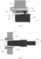
- Fig. 3 shows a schematic illustration of another adjustment bush assembly 110 of a hatch locking device 100.
- the adjustment bush assembly 110 of Fig. 3 differs from the adjustment bush assembly of Fig. 1 in that the second eccentric bush 114 has a conical shape. Furthermore, the second eccentric bush 114 comprises teeth 115 on a front side of the second eccentric bush 114 for rotating the second eccentric bush 114 in relation to the first eccentric bush 111. The teeth 115 are arranged circumferential around the second eccentric bush 114.
- the adjustment bush assembly 110 further comprises a nut 116 interacting with the first eccentric bush 111 for pressing the second eccentric bush 114 between the first eccentric bush and a fuselage frame 1.
- the first eccentric bush 111 contains a polygon socket, in particular a hexagon socket.
- the first eccentric bush 111 and the second eccentric bush 114 are oriented along the longitudinal axis X.
- the locking bolt 102 is receivable in the bolt receptacle of the first eccentric bush 111.
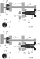
- Fig. 4A and 4B show a schematic illustration of an aircraft hatch 10 with a pull-in device 14, wherein Fig. 4A shows the pull-in device 14 in a starting condition and Fig. 4B shows the pull-in device 14 in a final condition.
- the aircraft hatch 10 comprises a hatch frame 11, a hatch locking device 100, a drive unit 12 and a drive system 13.
- the hatch locking device 100 is mounted to the hatch frame 11.
- a drivable spindle drive 101 of the hatch locking device 100 is fixed in relation to the hatch frame 11 along the longitudinal axis X.
- the drive unit 12 (not shown in Fig. 4A, 4B ) is mounted to the hatch frame 11 and drives the drivable spindle drive 101.
- the drive system 13 mechanically couples the drive unit 12 with the hatch locking device 100. Therefore, the drive system 13 comprises a main drive shaft.
- the pull-in device 14 is configured to force the aircraft hatch 10 to close.
- the pull-in device 14 comprises a hollow cam disc 15.
- the hollow cam disc 15 is mechanically coupled to the drive system 13 and configured to interact with a pin 2 mounted on a fuselage frame 1.
- the pull-in device 14 comprises a planetary gear 16.
- the planetary gear 16 is arranged between the hollow cam disc 15 and the drive system 13 for synchronizing the rotation of the hollow cam disc 15 and the rotation of the drivable spindle drive 101 such that the aircraft hatch 10 is at least almost closed before the bolt receptacle 112 receives the locking bolt 102.
- the longitudinal axis X of the hatch locking device 100 is offset to a longitudinal axis of the first eccentric bush 111, wherein the offset is more than an offset which can be fixed by self-centering of the conical locking bolt 102. Therefore, the locking bolt 102 is not able to be driven into the bolt receptacle of the first eccentric bush 111.
- the drive system 13 is in a reference position having an angle of 0° of a rotational axis, as it is illustrated in Fig. 4A .
- the longitudinal axis X of the locking bolt 102 basically corresponds to the longitudinal axis of the first eccentric bush 111. Thereby, basically includes the offset of both longitudinal axles less than an offset which can be fixed by self-centering of the conical locking bolt 102.
- the locking bolt 102 can be driven into the bolt receptacle 112 in the final condition, as it is indicated in Fig. 4B .
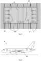
- Fig. 5 shows a schematic illustration of an aircraft hatch 10 with six hatch locking devices 100 each having one locking bolt 102 and with three hatch locking devices 100 each having two opposing locking bolts 102.
- the aircraft hatch 10 is attached by a hinge to a fuselage of an aircraft.
- the aircraft hatch 10 is attached on one side of the aircraft hatch 10 to the fuselage.
- the aircraft hatch 10 is attached by a multi-part hinge, and swivels outwards during the opening movement.
- the six hatch locking devices 100 with one locking bolt 102 are exemplarily arranged at a lateral side of the aircraft hatch, wherein the lateral side extends along the orientation of a fuselage frame 1.
- the three hatch locking devices 10 with two locking bolts 102 are arranged at a horizontal side of the aircraft hatch being not the hinged side, wherein the horizontal side extends perpendicular to the orientation of the fuselage frame 1.
- the aircraft hatch 10 comprises a drive system 13 which mechanically couples the drive unit 12 with the hatch locking devices 100.
- the drive system 13 comprises a main drive shaft configured to mechanically couple the three hatch locking devices 100 with two opposing locking bolts 102.
- the drive system 13 comprises two drive belts 13 configured to mechanically couple the main drive shaft 13 with the hatch locking devices 100 with one locking bolt 102.
- the drive system 13 can comprise a worm drive for mechanically coupling the drive unit 12 to the hatch locking devices 100.
- the aircraft hatch 10 and the hatch locking device 100 can transfer radial forces to align surfaces under cabin pressure. Moreover, they can transfer shear loads to stiffen a door cut-out and can transfer compressive forces along the longitudinal axis X to prevent clash.
- Fig. 6 shows a schematic illustration of an aircraft A with an aircraft hatch 10 comprising a hatch locking device 100.
- the aircraft hatch 10 is configured as a cargo hold hatch.
Landscapes
- Engineering & Computer Science (AREA)
- Mechanical Engineering (AREA)
- Aviation & Aerospace Engineering (AREA)
- Connection Of Plates (AREA)
- Power-Operated Mechanisms For Wings (AREA)
- Transmission Devices (AREA)
Abstract
Description
- The invention relates to a hatch locking device for an aircraft or spacecraft hatch as well as to an aircraft or spacecraft hatch containing such a hatch locking device. The invention is furthermore concerned with an aircraft or spacecraft containing such an aircraft or spacecraft hatch.
- Aircraft doors in a fuselage cell of an aircraft must transfer considerable peripheral loads. The greater the diameter of a fuselage cell the higher are the peripheral loads which arise in the fuselage cell structure. The load transfer between the aircraft door and the fuselage cell structure is commonly provided through a multiple of hooks swivel mounted on a shaft which engage round substantially horizontally fixed shaft sections in the area of the fuselage cell.
- High tensile forces act during the flight, in particular, in the case of relatively large aircraft doors or hatches, such as cargo hold hatches, for example. In addition, high load differences, for example in comparison between an unloaded and loaded cargo hold, can lead on ground to deformations or deflections occurring in the region of the hatch gaps, which deformations or deflections can impair the correct orientation of the hatch locking elements with respect to one another.
- Aspects of the invention may provide solutions for improving locking and securing of aircraft or spacecraft doors under different loads.
- According to the invention, this problem is solved in each case by the subject matters of the independent claims.
- According to a first aspect of the invention, a hatch locking device for an aircraft or spacecraft hatch is provided. The hatch locking device comprises a drivable spindle drive which extends in a longitudinal axis and is fixed in relation to a hatch frame of the aircraft or spacecraft hatch along the longitudinal axis. Furthermore, the hatch locking device comprises at least one locking bolt which is driven by the drivable spindle drive and is guided along the longitudinal axis and at least one adjustment bush assembly being mounted on a fuselage frame. The at least one adjustment bush assembly comprises a first eccentric bush having a bolt receptacle which is oriented centrally along the longitudinal axis for receiving the at least one locking bolt such that the hatch locking device is positive-locking connectable in two axles both being perpendicular to the longitudinal axis.
- According to a second aspect of the invention, an aircraft hatch or an spacecraft hatch comprising a hatch frame and a hatch locking device according to the invention is provided. The hatch locking device is mounted to the hatch frame, wherein the drivable spindle drive is fixed in relation to the hatch frame along the longitudinal axis. Furthermore, the aircraft hatch or the spacecraft hatch comprises a drive unit which is mounted to the hatch frame and drives the drivable spindle drive.
- According to a third aspect of the invention, an aircraft or spacecraft comprising an aircraft hatch or an spacecraft hatch according to the invention is provided.
- A fundamental concept of the invention is to provide a bolt closure for an aircraft hatch, which bolt closure can have a positive-locking connection in at least two directions as well as one-way in a third direction, in particular in Y- and Z-direction as well as in +X-direction. That means in X-direction the positive-locking connection can only be provided in pushing direction of the locking bolt to the adjustment bush assembly. Moreover, the bolt closure can transmit forces in X-, Y- and Z-direction and torques, or also called moments, in Y- and Z-direction in case of movement of the aircraft or spacecraft hatch in relation to the fuselage frame by loads during flight, for example, or in case of self-centering during a locking process in case of misalignment caused by loading differences, for example. Furthermore, the spindle drive and the adjustment bush assembly can be mounted reversely.
- A particular advantage in the solution according to an aspect of the invention is that manufacturing tolerances of the hatch panel and/or the hatch frame can be compensated for translationally in all directions by the adjustable bush assembly; the hatch locking device makes self-centering of the hatch during closure and self-centering of the locking bolt during locking possible by the conical bush reception. In addition, one particular advantage results from the screw drive actuation which has high power and increases the reliability of the locking and unlocking. Moreover, the drivable spindle drive is self-securing.
- Advantageous embodiments and further developments emerge from the description with reference to the figures.
- According to some aspects of the hatch locking device according to the invention, the at least one locking bolt comprises two opposing locking bolts which are driven by the drivable spindle drive and are guided along the longitudinal axis, and wherein the at least one adjustment bush assembly comprises two adjustment bush assemblies each being mounted on a fuselage frame. Both locking bolts are driven by the drivable spindle drive simultaneously. Therefore, one of the two locking bolts can comprise a left-hand thread, wherein the other locking bolt can comprise a right-hand thread.
- According to some further aspects of the hatch locking device according to the invention, the two adjustment bush assemblies are configured to receive the two opposing locking bolts such that the hatch locking device is positive-locking connectable in the longitudinal axis. Thus, the hatch locking device can have a positive-locking connection in all directions, in particular in X-, Y- and Z-direction, wherein the longitudinal axis represents the X-direction. The hatch locking device cannot pop out of a locked position.
- According to some further aspects of the hatch locking device according to the invention, an end region of the at least one locking bolt is encased in a bolt bush, wherein the bolt bush slides inside the drivable spindle drive for supporting the at least one locking bolt against a torque perpendicular to the longitudinal axis. Higher torques can be withstood thereby. The end region of the at least one locking bolt provides a higher leverage to the hatch frame than the thread of the drivable spindle drive.
- According to some further aspects of the hatch locking device according to the invention, the at least one adjustment bush assembly further comprises a second eccentric bush which partly surrounds the first eccentric bush on its outer surface, wherein the first eccentric bush and the second eccentric bush each basically comprise a same axle offset. Thus, the axle offset of each eccentric bush can be combined to provide many different positions for the bolt receptacle to receive the locking bolt in case the longitudinal axis of the hatch locking device is offset to the longitudinal axis of the adjustment bush assembly. Furthermore, in case the longitudinal axis of the hatch locking device corresponds to the longitudinal axis of the adjustment bush assembly, the first eccentric bush and the second eccentric bush both having the same axle offset can be balanced out such that the axle offset provided by the first eccentric bush is compensated by the axle offset of the second eccentric bush.
- According to some further aspects of the hatch locking device according to the invention, the second eccentric bush has a conical shape and comprises teeth on a front side for rotating the second eccentric bush in relation to the first eccentric bush, wherein the at least one adjustment bush assembly further comprises a nut interacting with the first eccentric bush for pressing the second eccentric bush between the first eccentric bush and the fuselage frame. Thus, the conical shape can increase the axial load capability. The radial preload prevents the adjustment bush assembly from rotating as a result of the torque caused by the transverse force and eccentricity or as a result of the friction between the locking bolt and the first eccentric bush. Hence, a continuous adjustment of the offset of the first eccentric bush and the second eccentric bush can be provided. The centric recess of the second eccentric bush assist to rotate the second eccentric bush in relation to the first eccentric bush. Furthermore, an axial adjustment of the locking bolt in relation to the first eccentric bush can be provided by a selection of the first eccentric bush with an appropriate inner diameter.
- According to some further aspects of the hatch locking device according to the invention, wherein the at least one adjustment bush assembly further comprises a shim washer for adapting a distance between the at least one locking bolt and the first eccentric bush along the longitudinal axis.
- According to some further aspects of the hatch locking device according to the invention, the first eccentric bush is configured as a serrated, conical eccentric bush and comprises teeth on a front side for avoiding a rotation of the serrated, conical eccentric bush in relation to the fuselage frame. That means the first eccentric bush has an outer conical shape and comprises teeth on a front side for avoiding a rotation in relation to the second conical bush whereby the second conical bush is rotationally fixed in relation to the fuselage frame by serration. Furthermore, an axial adjustment of the locking bolt in relation to the first eccentric bush can be provided by a selection of the first eccentric bush with an appropriate inner diameter.
- According to some aspects the aircraft or spacecraft hatch according to the invention comprises at least two hatch locking devices, wherein at least one hatch locking device comprises two opposing locking bolts and wherein at least one hatch locking device comprises one locking bolt. The hatch locking device with one locking bolt can be arranged at a lateral side of the aircraft or spacecraft hatch, wherein the lateral side extends along the orientation of the fuselage frame. The hatch locking device with two locking bolts can be arranged at a horizontal side of the aircraft or spacecraft hatch, wherein the horizontal side extends perpendicular to the orientation of the fuselage frame. Therefore, the hatch locking device with two locking bolts can be arranged in relation to the fuselage frame such that both adjustment bush assemblies can be supported by two fuselage frames, one fuselage frame being on each side.
- According to some further aspects the aircraft or spacecraft hatch according to the invention further comprises a drive system which mechanically couples the drive unit with the hatch locking device, wherein the drive system comprises at least one of the following: a main drive shaft, a drive belt or a worm drive. Thus, the drive unit does not need to be arranged next to the hatch locking device. In particular when the aircraft hatch comprises more than one hatch locking device the drive system can couple each hatch locking device to the drive unit.
- According to some further aspects the aircraft or spacecraft hatch according to the invention further comprises a pull-in device for forcing the aircraft or spacecraft hatch to close, wherein the pull-in device comprises a hollow cam disc which is mechanically coupled to the drive system and configured to interact with a pin being mounted on a fuselage frame. Due to different loading conditions the aircraft or spacecraft hatch might not close completely without assistance. Instead small gaps between the fuselage frame and the aircraft or spacecraft hatch can remain such that the locking bolt can not be received in the first eccentric bush. In particular, the pull-in device can be used when the small gaps have a distance from the pin to the hollow cam disc of 50 mm or less, preferably of 40 mm or less. In other words, the pull-in device can be used when the misalignment between the pin and the hollow cam disc is 50 mm or less. Therefore, the pull-in device is configured to interact with the pin to completely close the aircraft or spacecraft hatch and to align the locking bolt to the bolt receptacle of the first eccentric bush.
- According to some further aspects of the aircraft or spacecraft hatch according to the invention, the pull-in device further comprises a planetary gear arranged between the hollow cam disc and the drive system for synchronizing the rotation of the hollow cam disc and the rotation of the drivable spindle drive such that the aircraft or spacecraft hatch is at least almost closed before the bolt receptacle receives the locking bolt. The planetary gear increases the torque and hence the pull-in force.
- According to some aspects of the aircraft or spacecraft according to the invention, the aircraft or spacecraft hatch is configured as a cargo hold hatch.
- The present invention is explained more specifically below on the basis of the exemplary embodiments indicated in the schematic figures, in which:
- Fig. 1
- shows a schematic illustration of a hatch locking device with two opposing locking bolts in a locked condition according to an embodiment of the invention;
- Fig. 2
- shows a schematic illustration of an adjustment bush assembly of a hatch locking device according to a further embodiment of the invention;
- Fig. 3
- shows a schematic illustration of another adjustment bush assembly of a hatch locking device according to a further embodiment of the invention;
- Fig. 4A, 4B
- show a schematic illustration of an aircraft hatch with a pull-in device according to a further embodiment of the invention, wherein
Fig. 4A shows the pull-in device in a starting condition andFig. 4B shows the pull-in device in a final condition; - Fig. 5
- shows a schematic illustration of an aircraft hatch with six hatch locking devices each having one locking bolt and with three hatch locking devices each having two locking bolts according to a further embodiment of the invention; and
- Fig. 6
- shows a schematic illustration of an aircraft with an aircraft hatch comprising a hatch locking device according to a further embodiment of the invention.
- The accompanying figures are intended to convey a further understanding of the embodiments of the invention. They illustrate embodiments and are used in conjunction with the description to explain principles and concepts of the invention. Other embodiments and many of the cited advantages emerge in light of the drawings. The elements of the drawings are not necessarily shown to scale in relation to one another. Direction-indicating terminology such as for example "at the top", "at the bottom", "on the left", "on the right", "above", "below", "horizontally", "vertically", "at the front", "at the rear" and similar statements are merely used for explanatory purposes and do not serve to restrict the generality to specific configurations as shown in the figures.
- In the figures of the drawing, elements, features and components that are the same, have the same function and have the same effect are each provided with the same reference signs - unless explained otherwise.
-
Fig. 1 shows a schematic illustration of ahatch locking device 100 with two opposing lockingbolts 102 in a locked condition. In the illustrated locked condition, thehatch locking device 100 is integrated in anaircraft hatch 10 and locked to afuselage frame 1. - The
hatch locking device 100 comprises a drivable spindle drive 101 which extends in a longitudinal axis X. Thedrivable spindle drive 101 is fixed in relation to ahatch frame 11 of theaircraft hatch 10 along the longitudinal axis X. In particular, thedrivable spindle drive 101 is arranged between two adjacent hatch frames 11. - Thereby, the
drivable spindle drive 101 is mounted to the two adjacent hatch frames 11 by means of aroller bearing 107, which is supported by thehatch frame 11. Preferably, theroller bearing 107 is tapered. Furthermore, thedrivable spindle drive 101 comprises a spur gear which is engaged with adrive system 13 of theaircraft hatch 10. InFig. 1 , thedrive system 13 comprises a spur gear configured to be engaged with the spur gear of thedrivable spindle drive 101, for example. - Further, the
hatch locking device 100 comprises the two opposing lockingbolts 102 which are driven by thedrivable spindle drive 101. A head region of the two lockingbolts 102 contains a conical shape. The two opposing lockingbolts 102 are guided along the longitudinal axis X. For driving the two opposing lockingbolts 102 thedrivable spindle drive 101 is rotated about the longitudinal axis X. Therefore, one of the two lockingbolts 102 contains a left-hand thread, wherein theother locking bolt 102 contains a right-hand thread. For example, the downwards oriented lockingbolt 102 contains the left-hand thread and the upwards oriented lockingbolt 102 contains the right-hand thread, as it is illustrated inFig. 1 . Furthermore, thedrivable spindle drive 101 is self-securing, which means the lockingbolts 102 are not able to drive thedrivable spindle drive 101. Optionally, thedrivable spindle drive 101 comprises a trapezoidal inner thread and the two lockingbolts 102 comprise a corresponding trapezoidal outer thread. - Additionally, the
hatch locking device 100 comprises twoadjustment bush assemblies 110 each being mounted on thefuselage frame 1. The twoadjustment bush assemblies 110 are configured to receive the two opposing lockingbolts 102 such that thehatch locking device 100 is positive-locking connectable in the longitudinal axis X and in two axles Y, Z both being perpendicular to the longitudinal axis X. - Each
adjustment bush assembly 110 comprises a firsteccentric bush 111. The firsteccentric bush 111 contains abolt receptacle 112 which is oriented centrally along the longitudinal axis X for receiving thelocking bolt 102 such that thehatch locking device 100 is positive-locking connectable in all directions, i.e. the axles X, Y and Z. Thebolt receptacle 112 has a conical shape corresponding to the conical shape of thelocking bolt 102. In this embodiment, the firsteccentric bush 111 contains a cylindrical shell surface, but is not limited to such a shape. - Moreover, each
adjustment bush assembly 110 comprises a secondeccentric bush 114. The secondeccentric bush 114 partly surrounds the firsteccentric bush 111 on its outer surface. Preferably, the firsteccentric bush 111 and the secondeccentric bush 114 each basically comprise a same axle offset. - Each
adjustment bush assembly 110 further comprises ashim washer 117 for adapting a distance between the at least onelocking bolt 102 and the firsteccentric bush 111 along the longitudinal axis X. For example, theadjustment bush assembly 110 includes at least one fastening screw for fastening theadjustment bush assembly 110 or the firsteccentric bush 111 at thefuselage frame 11. The fastening screw is oriented parallel to the longitudinal axis X. By varying a thickness of theshim washer 117 the firsteccentric bush 111 can be positioned closer to or further away from the lockingbolt 102. At an installation of thehatch locking device 100 the thickness of the shim washer can be chosen such that the two opposing lockingbolts 102 are received in the firsteccentric bushes 111 basically at the same time. That means depending on manufacturing tolerances of thefuselage frame 1 and thehatch frame 11, respectively, theshim washer 117 compensates a distance along the longitudinal axis X. - Furthermore, axial forces are transferred by the conical shape of the
locking bolt 102 via thedrivable spindle drive 101 and via the taperedroller bearing 107 to thehatch frame 11. Alternatively or additionally, the two opposing lockingbolts 102 are arranged between two adjacent hatch frames 11. - Further, an end region of the
locking bolt 102 can be encased in abolt bush 103, as illustrated inFig. 1 . Thebolt bush 103 can slide inside the drivable spindle drive 101 for supporting thelocking bolt 102 against a torque perpendicular to the longitudinal axis X. - Preferably, the
hatch frame 11 houses ahatch bush 104 which is penetrated by theslidable locking bolt 102. In particular, thehatch bush 104 is fixed in relation to thehatch frame 11. - Optionally, the locking
bolt 102 comprises agroove 105 oriented along the longitudinal axis X for securing thelocking bolt 102 against rotation around the longitudinal axis X. Thereby, a bolt or apin 106 causes a positive-locking connection between the lockingbolt 102, thehatch bush 104 and thehatch frame 11 when being inserted into thegroove 105 through thehatch bush 104 and thehatch frame 11, as it is illustrated in view A-A inFig. 1 . -
Fig. 2 shows a schematic illustration of anadjustment bush assembly 110 of ahatch locking device 100. - The
adjustment bush assembly 110 ofFig. 2 differs from the adjustment bush assembly ofFig. 1 in that the firsteccentric bush 111 is configured as a serrated, conical eccentric bush. The first serrated, conicaleccentric bush 111 comprisesteeth 118 on a front side of the serrated, conicaleccentric bush 111 for avoiding a rotation of the serrated, conicaleccentric bush 111 in relation to afuselage frame 1. - Further, the second
eccentric bush 114 is configured as serrated, conical eccentric bush. The second serrated, conicaleccentric bush 114 comprisesteeth 118 on a front side and on a back side of the serrated, conicaleccentric bush 114. - The first serrated, conical
eccentric bush 111 and the second serrated, conicaleccentric bush 114 are oriented along the longitudinal axis X. - The
teeth 118 are arranged circumferential around the first serrated, conicaleccentric bush 111 and the second serrated, conicaleccentric bush 114, respectively. The first serrated, conicaleccentric bush 111 and the second serrated conicaleccentric bush 114 are mounted to thefuselage frame 1 by means of aserrated plate 113. Theserrated plate 113 contains correspondingteeth 118 for engaging with theteeth 118 of theeccentric bushes teeth 118 preferably are configured to provide a small adjustable rotation step of the first serrated, conicaleccentric bush 111 in relation to theserrated plate 113 and of the second serrated, conicaleccentric bush 114 in relation to theserrated plate 113. Theserrated plate 113 can be mounted to the firsteccentric bush 111 and axially fixed by a plate mounted to thefuselage frame 1 by means of a fastening screw or the like. For example, theserrated plate 113 on the left-hand side can be screwed to thefuselage frame 1. Then the second serrated conicaleccentric bush 114 can be mounted to thefuselage frame 1. After that, theserrated plate 113 on the right-hand side can be mounted interacting with the second serrated conicaleccentric bush 114. Finally, the first serrated, conicaleccentric bush 111 can be mounted interacting with theserrated plate 113 on the right-hand side inFig. 2 . - For example, a bore of the
fuselage frame 1 in which theadjustment bush assembly 110 is mounted is reference for interlocking of thefuselage frame 1 and the second serrated, conicaleccentric bush 114. The bore in the second serrated, conicaleccentric bush 114 is reference for interlocking of the first and second serrated, conicaleccentric bush serrated plate 113 on the left-hand and the right-hand side. - The
locking bolt 102 is receivable in the bolt receptacle of the first serrated, conicaleccentric bush 111. -
Fig. 3 shows a schematic illustration of anotheradjustment bush assembly 110 of ahatch locking device 100. - The
adjustment bush assembly 110 ofFig. 3 differs from the adjustment bush assembly ofFig. 1 in that the secondeccentric bush 114 has a conical shape. Furthermore, the secondeccentric bush 114 comprisesteeth 115 on a front side of the secondeccentric bush 114 for rotating the secondeccentric bush 114 in relation to the firsteccentric bush 111. Theteeth 115 are arranged circumferential around the secondeccentric bush 114. - Optionally, the
adjustment bush assembly 110 further comprises anut 116 interacting with the firsteccentric bush 111 for pressing the secondeccentric bush 114 between the first eccentric bush and afuselage frame 1. - For countering the
nut 116 the firsteccentric bush 111 contains a polygon socket, in particular a hexagon socket. - The first
eccentric bush 111 and the secondeccentric bush 114 are oriented along the longitudinal axis X. - The
locking bolt 102 is receivable in the bolt receptacle of the firsteccentric bush 111. -
Fig. 4A and 4B show a schematic illustration of anaircraft hatch 10 with a pull-indevice 14, whereinFig. 4A shows the pull-indevice 14 in a starting condition andFig. 4B shows the pull-indevice 14 in a final condition. - The
aircraft hatch 10 comprises ahatch frame 11, ahatch locking device 100, adrive unit 12 and adrive system 13. - The
hatch locking device 100 is mounted to thehatch frame 11. A drivable spindle drive 101 of thehatch locking device 100 is fixed in relation to thehatch frame 11 along the longitudinal axis X. - The drive unit 12 (not shown in
Fig. 4A, 4B ) is mounted to thehatch frame 11 and drives thedrivable spindle drive 101. - The
drive system 13 mechanically couples thedrive unit 12 with thehatch locking device 100. Therefore, thedrive system 13 comprises a main drive shaft. - The pull-in
device 14 is configured to force theaircraft hatch 10 to close. Thereby, the pull-indevice 14 comprises ahollow cam disc 15. Thehollow cam disc 15 is mechanically coupled to thedrive system 13 and configured to interact with apin 2 mounted on afuselage frame 1. - Further the pull-in
device 14 comprises aplanetary gear 16. Theplanetary gear 16 is arranged between thehollow cam disc 15 and thedrive system 13 for synchronizing the rotation of thehollow cam disc 15 and the rotation of the drivable spindle drive 101 such that theaircraft hatch 10 is at least almost closed before thebolt receptacle 112 receives thelocking bolt 102. - In the starting condition the
hollow cam disk 15 is configured to come in close vicinity of thepin 2. The longitudinal axis X of thehatch locking device 100 is offset to a longitudinal axis of the firsteccentric bush 111, wherein the offset is more than an offset which can be fixed by self-centering of theconical locking bolt 102. Therefore, the lockingbolt 102 is not able to be driven into the bolt receptacle of the firsteccentric bush 111. Thedrive system 13 is in a reference position having an angle of 0° of a rotational axis, as it is illustrated inFig. 4A . - Between the starting condition and the final condition the
hollow cam disk 15 engages behind thepin 2 and pulls theaircraft hatch 10 towards thefuselage frame 1. - In the final condition of the pull-in
device 14 the longitudinal axis X of thelocking bolt 102 basically corresponds to the longitudinal axis of the firsteccentric bush 111. Thereby, basically includes the offset of both longitudinal axles less than an offset which can be fixed by self-centering of theconical locking bolt 102. Thus, the lockingbolt 102 can be driven into thebolt receptacle 112 in the final condition, as it is indicated inFig. 4B . - In a locked position of the
locking bolt 102 there is a gap between thehollow cam disc 15 and thepin 2. Hence, there is no load on thehollow cam disc 15 in the locked position. -
Fig. 5 shows a schematic illustration of anaircraft hatch 10 with sixhatch locking devices 100 each having onelocking bolt 102 and with threehatch locking devices 100 each having two opposing lockingbolts 102. - The
aircraft hatch 10 is attached by a hinge to a fuselage of an aircraft. Preferably, theaircraft hatch 10 is attached on one side of theaircraft hatch 10 to the fuselage. More particularly, theaircraft hatch 10 is attached by a multi-part hinge, and swivels outwards during the opening movement. - The six
hatch locking devices 100 with onelocking bolt 102 are exemplarily arranged at a lateral side of the aircraft hatch, wherein the lateral side extends along the orientation of afuselage frame 1. The threehatch locking devices 10 with two lockingbolts 102 are arranged at a horizontal side of the aircraft hatch being not the hinged side, wherein the horizontal side extends perpendicular to the orientation of thefuselage frame 1. - Further, the
aircraft hatch 10 comprises adrive system 13 which mechanically couples thedrive unit 12 with thehatch locking devices 100. Thereby, thedrive system 13 comprises a main drive shaft configured to mechanically couple the threehatch locking devices 100 with two opposing lockingbolts 102. Furthermore, thedrive system 13 comprises twodrive belts 13 configured to mechanically couple themain drive shaft 13 with thehatch locking devices 100 with onelocking bolt 102. Alternatively or additionally, thedrive system 13 can comprise a worm drive for mechanically coupling thedrive unit 12 to thehatch locking devices 100. - The
aircraft hatch 10 and thehatch locking device 100, respectively, can transfer radial forces to align surfaces under cabin pressure. Moreover, they can transfer shear loads to stiffen a door cut-out and can transfer compressive forces along the longitudinal axis X to prevent clash. -
Fig. 6 shows a schematic illustration of an aircraft A with anaircraft hatch 10 comprising ahatch locking device 100. Optionally, theaircraft hatch 10 is configured as a cargo hold hatch. - In the detailed description above, various features have been combined in one or more examples in order to improve the rigorousness of the illustration. However, it should be clear in this case that the above description is of merely illustrative but in no way restrictive nature. It serves to cover all alternatives, modifications and equivalents of the various features and exemplary embodiments. Many other examples will be immediately and directly clear to a person skilled in the art on the basis of his knowledge in the art in consideration of the above description.
- The exemplary embodiments have been chosen and described in order to be able to present the principles underlying the invention and their application possibilities in practice in the best possible way. As a result, those skilled in the art can optimally modify and utilize the invention and its various exemplary embodiments with regard to the intended purpose of use. In the claims and the description, the terms "including" and "having" are used as neutral linguistic concepts for the corresponding terms "comprising". Furthermore, use of the terms "a", "an" and "one" shall not in principle exclude the plurality of features and components described in this way.
- While at least one exemplary embodiment of the present invention(s) is disclosed herein, it should be understood that modifications, substitutions and alternatives may be apparent to one of ordinary skill in the art and can be made without departing from the scope of this disclosure. This disclosure is intended to cover any adaptations or variations of the exemplary embodiment(s). In addition, in this disclosure, the terms "comprise" or "comprising" do not exclude other elements or steps, the terms "a" or "one" do not exclude a plural number, and the term "or" means either or both. Furthermore, characteristics or steps which have been described may also be used in combination with other characteristics or steps and in any order unless the disclosure or context suggests otherwise. This disclosure hereby incorporates by reference the complete disclosure of any patent or application from which it claims benefit or priority.
-
- 1
- fuselage frame
- 2
- pin
- 10
- aircraft or spacecraft hatch
- 11
- hatch frame
- 12
- drive unit
- 13
- drive system
- 14
- pull-in device
- 15
- hollow cam disc
- 16
- planetary gear
- 100
- hatch locking device
- 101
- spindle drive
- 102
- locking bolt
- 103
- bolt bush
- 104
- hatch bush
- 105
- groove
- 106
- bolt or pin
- 107
- roller bearing
- 110
- adjustment bush assembly
- 111
- first eccentric bush
- 112
- bolt receptacle
- 113
- serrated plate
- 114
- second eccentric bush
- 115
- teeth
- 116
- nut
- 117
- shim washer
- 118
- teeth
- A
- aircraft or spacecraft
- X
- longitudinal axis
- Y
- axis
- Z
- axis
Claims (15)
- Hatch locking device (100) for an air- or spacecraft hatch (10), comprising:a drivable spindle drive (101) which extends in a longitudinal axis (X) and is fixed in relation to a hatch frame (11) of the air- or spacecraft hatch (10) along the longitudinal axis (X);at least one locking bolt (102) which is driven by the drivable spindle drive (101) and is guided along the longitudinal axis (X); andat least one adjustment bush assembly (110) being mounted on a fuselage frame (1) and comprising a first eccentric bush (111) having a bolt receptacle (112) which is oriented centrally along the longitudinal axis (X) for receiving the at least one locking bolt (102) such that the hatch locking device (100) is positive-locking connectable in two axles (Y, Z) both being perpendicular to the longitudinal axis (X).
- Hatch locking device (100) according to claim 1, wherein the at least one locking bolt (102) comprises two opposing locking bolts which are driven by the drivable spindle drive (101) and are guided along the longitudinal axis (X), and wherein the at least one adjustment bush assembly (110) comprises two adjustment bush assemblies each being mounted on a fuselage frame (1).
- Hatch locking device (100) according to claim 2, wherein the two adjustment bush assemblies (110) are configured to receive the two opposing locking bolts (102) such that the hatch locking device (100) is positive-locking connectable in the longitudinal axis (X).
- Hatch locking device (100) according to one of the preceding claims,
wherein an end region of the at least one locking bolt (102) is encased in a bolt bush (103), wherein the bolt bush (103) slides inside the drivable spindle drive (101) for supporting the at least one locking bolt against a torque perpendicular to the longitudinal axis (X). - Hatch locking device (100) according to one of the preceding claims,
wherein the at least one adjustment bush assembly (110) further comprises a second eccentric bush (114) which partly surrounds the first eccentric bush (111) on its outer surface, wherein the first eccentric bush (111) and the second eccentric bush (114) each basically comprise a same axle offset. - Hatch locking device (100) according to claim 5, wherein the second eccentric bush (114) has a conical shape and comprises teeth (115) on a front side for rotating the second eccentric bush in relation to the first eccentric bush (111), wherein the at least one adjustment bush assembly (110) further comprises a nut (116) interacting with the first eccentric bush (111) for pressing the second eccentric bush (114) between the first eccentric bush and a fuselage frame (1).
- Hatch locking device (100) according to one of claims 1 to 5, wherein the at least one adjustment bush assembly (110) further comprises a shim washer (117) for adapting a distance between the at least one locking bolt (102) and the first eccentric bush (111) along the longitudinal axis (X).
- Hatch locking device (100) according to one of claims 1 to 5, wherein the first eccentric bush (111) is configured as a serrated, conical eccentric bush and comprises teeth (118) on a front side for avoiding a rotation of the serrated, conical eccentric bush in relation to a fuselage frame (1).
- Air- or spacecraft hatch (10), comprising:a hatch frame (11);a hatch locking device (100) according to one of claims 1 to 8 which is mounted to the hatch frame (11), wherein the drivable spindle drive (101) is fixed in relation to the hatch frame (11) along the longitudinal axis (X); and a drive unit (12) which is mounted to the hatch frame (11) and drives the drivable spindle drive (101).
- Air- or spacecraft hatch (10) according to claim 9, comprising at least two hatch locking devices (100), wherein at least one hatch locking device (100) comprises two opposing locking bolts (102) and wherein at least one hatch locking device (100) comprises one locking bolt (102).
- Air- or spacecraft hatch (10) according to claim 9 or 10, further comprising a drive system (13) which mechanically couples the drive unit (12) with the hatch locking device (100), wherein the drive system (13) comprises at least one of the following: a main drive shaft, a drive belt or a worm drive.
- Air- or spacecraft hatch (10) according to one of claims 9 to 11, further comprising a pull-in device (14) for forcing the air- or spacecraft hatch (10) to close, wherein the pull-in device (14) comprises a hollow cam disc (15) which is mechanically coupled to the drive system (13) and configured to interact with a pin (2) being mounted on a fuselage frame.
- Air- or spacecraft hatch (10) according to one of claims 9 to 12, wherein the pull-in device (14) further comprises a planetary gear (16) arranged between the hollow cam disc (15) and the drive system (13) for synchronizing the rotation of the hollow cam disc (15) and the rotation of the drivable spindle drive (101) such that the aircraft or spacecraft hatch (10) is at least almost closed before the bolt receptacle (112) receives the locking bolt (102).
- Air- or spacecraft (A) with an air- or spacecraft hatch (10) according to one of claims 9 to 13.
- Air- or spacecraft (A) according to claim 14, wherein the air- or spacecraft hatch (10) is configured as a cargo hold hatch.
Priority Applications (3)
| Application Number | Priority Date | Filing Date | Title |
|---|---|---|---|
| EP22214514.6A EP4389591B1 (en) | 2022-12-19 | 2022-12-19 | Hatch locking device, air- or spacecraft hatch and air- or spacecraft |
| US18/543,882 US20240200374A1 (en) | 2022-12-19 | 2023-12-18 | Hatch locking device, air- or spacecraft hatch and air- or spacecraft |
| CN202311749954.8A CN118223743A (en) | 2022-12-19 | 2023-12-19 | Door locking device, aircraft or spacecraft door, and aircraft or spacecraft |
Applications Claiming Priority (1)
| Application Number | Priority Date | Filing Date | Title |
|---|---|---|---|
| EP22214514.6A EP4389591B1 (en) | 2022-12-19 | 2022-12-19 | Hatch locking device, air- or spacecraft hatch and air- or spacecraft |
Publications (2)
| Publication Number | Publication Date |
|---|---|
| EP4389591A1 true EP4389591A1 (en) | 2024-06-26 |
| EP4389591B1 EP4389591B1 (en) | 2025-06-18 |
Family
ID=84537972
Family Applications (1)
| Application Number | Title | Priority Date | Filing Date |
|---|---|---|---|
| EP22214514.6A Active EP4389591B1 (en) | 2022-12-19 | 2022-12-19 | Hatch locking device, air- or spacecraft hatch and air- or spacecraft |
Country Status (3)
| Country | Link |
|---|---|
| US (1) | US20240200374A1 (en) |
| EP (1) | EP4389591B1 (en) |
| CN (1) | CN118223743A (en) |
Citations (3)
| Publication number | Priority date | Publication date | Assignee | Title |
|---|---|---|---|---|
| US4042193A (en) * | 1975-07-19 | 1977-08-16 | Vereinigte Flugtechnische Werke-Fokker Gmbh | Safety device for aircraft doors or hatches |
| US20100252679A1 (en) * | 2007-10-30 | 2010-10-07 | Airbus Operations Gmbh | Emergency exit hatch for exiting a cabin module in an emergency and entering the same |
| US20220380016A1 (en) * | 2021-05-31 | 2022-12-01 | Airbus Operations Gmbh | Hatch locking device, and aircraft with hatch locking device |
Family Cites Families (22)
| Publication number | Priority date | Publication date | Assignee | Title |
|---|---|---|---|---|
| US1856091A (en) * | 1932-05-03 | Door lock | ||
| US1382758A (en) * | 1919-10-16 | 1921-06-28 | Martha A Brown | Sash-fastener |
| US2071092A (en) * | 1935-11-05 | 1937-02-16 | Troy Max | Lock |
| US3043410A (en) * | 1959-08-10 | 1962-07-10 | Boeing Co | Locking means for swing-tail airplanes |
| US3158217A (en) * | 1961-06-26 | 1964-11-24 | Dennis T Johnson | Scale load platform lock |
| US3396999A (en) * | 1966-03-15 | 1968-08-13 | William F. Knapp | Safety lock for automotive vehicles |
| FR2011181A1 (en) * | 1968-06-19 | 1970-02-27 | Kiekert Soehne Arn | |
| US3638983A (en) * | 1969-06-02 | 1972-02-01 | Lockheed Aircraft Corp | Locking mechanism and actuating means therefor |
| US4974888A (en) * | 1988-07-25 | 1990-12-04 | The Vendo Company | Fastening apparatus |
| US5280973A (en) * | 1992-09-25 | 1994-01-25 | The United States Of America As Represented By The Secretary Of The Army | Hatch securing mechanism |
| US5597187A (en) * | 1995-03-23 | 1997-01-28 | Hjorth; Terry M. | Floating latching mechanism for a safe door |
| DE29703852U1 (en) * | 1997-03-03 | 1997-04-17 | Eff-Eff Fritz Fuss Gmbh & Co. Kgaa, 72458 Albstadt | Device for adjusting a locking pin |
| AU2002227200A1 (en) * | 2000-11-02 | 2002-05-15 | Best Access Systems | Vending machine lock |
| DE20112738U1 (en) * | 2001-08-08 | 2001-11-22 | Bks Gmbh | Locking trough |
| US7014227B2 (en) * | 2003-05-09 | 2006-03-21 | The Langenau Manufacturing Company | Wedge bar locking mechanism |
| EP1696093A1 (en) * | 2005-01-28 | 2006-08-30 | Michel Flon | Door shutter mechanism |
| DE202005007578U1 (en) * | 2005-05-13 | 2006-09-21 | Niemann, Hans Dieter | Lock for the external door of a building comprises a latch having an actuating device which releases a sliding element from a transition unit in an emergency |
| US7181814B1 (en) * | 2005-11-14 | 2007-02-27 | Matthews Resources, Inc. | Burial casket with wedge bar lock |
| KR200426484Y1 (en) * | 2006-06-07 | 2006-09-19 | 김용범 | Window lock |
| DE102010013715B4 (en) * | 2010-04-02 | 2015-01-15 | Airbus Operations Gmbh | An aircraft door latch mechanism, method of locking an aircraft door and aircraft door |
| KR102297451B1 (en) * | 2021-01-07 | 2021-09-02 | 주식회사 대흥이티에스 | Blast proof door and blast proof chamber facility including the blast proof door |
| TWI800000B (en) * | 2021-09-22 | 2023-04-21 | 王建和 | Building formwork device with locking device |
-
2022
- 2022-12-19 EP EP22214514.6A patent/EP4389591B1/en active Active
-
2023
- 2023-12-18 US US18/543,882 patent/US20240200374A1/en active Pending
- 2023-12-19 CN CN202311749954.8A patent/CN118223743A/en active Pending
Patent Citations (3)
| Publication number | Priority date | Publication date | Assignee | Title |
|---|---|---|---|---|
| US4042193A (en) * | 1975-07-19 | 1977-08-16 | Vereinigte Flugtechnische Werke-Fokker Gmbh | Safety device for aircraft doors or hatches |
| US20100252679A1 (en) * | 2007-10-30 | 2010-10-07 | Airbus Operations Gmbh | Emergency exit hatch for exiting a cabin module in an emergency and entering the same |
| US20220380016A1 (en) * | 2021-05-31 | 2022-12-01 | Airbus Operations Gmbh | Hatch locking device, and aircraft with hatch locking device |
Also Published As
| Publication number | Publication date |
|---|---|
| CN118223743A (en) | 2024-06-21 |
| US20240200374A1 (en) | 2024-06-20 |
| EP4389591B1 (en) | 2025-06-18 |
Similar Documents
| Publication | Publication Date | Title |
|---|---|---|
| US6457674B2 (en) | Method and device for closing a door of an aircraft | |
| EP2554471B1 (en) | Loads interface, particularly a loads interface of an aircraft structure | |
| US8915017B2 (en) | Drive device for entrance and exit devices comprising a safety coupling | |
| EP3168138A1 (en) | Aircraft door assembly | |
| US8783616B2 (en) | Loads interface, particularly a loads interface for a plug type aircraft door | |
| CN115384755B (en) | Cabin door of pressurized cabin | |
| US20200181948A1 (en) | System for latching and locking an aircraft door | |
| US20190323563A1 (en) | Compressible driveshaft | |
| EP4389591B1 (en) | Hatch locking device, air- or spacecraft hatch and air- or spacecraft | |
| US20190338810A1 (en) | Driveshaft locking mechanism | |
| US7959195B2 (en) | Lock arrangement | |
| EP4389590A1 (en) | Air- or spacecraft hatch and air- or spacecraft | |
| CN209037880U (en) | A kind of the hatch door retaining mechanism and bay door system of spacecraft | |
| CA3112160C (en) | Double translating plug-type passenger entry door | |
| CA3172570A1 (en) | A cargo door with a fail-safe mechanism | |
| US20220355936A1 (en) | Fastening device for releasable connection to a perforated rail of an aircraft and method of assembly | |
| CN115478740B (en) | Door lock device and aircraft with a door lock device | |
| EP4545403A1 (en) | Hatch locking device, aircraft or spacecraft hatch and aircraft or spacecraft | |
| US20250304242A1 (en) | Interface for wing folding mechanism of an aircraft | |
| US20190376539A1 (en) | Systems and apparatuses for supporting a fastener | |
| WO2018203805A1 (en) | A body structure of a vehicle comprising a door structure and a modular locking mechanism | |
| US11305870B2 (en) | Wheel actuator locking mechanism | |
| US20260097840A1 (en) | Wing tip mechanism | |
| US20020104926A1 (en) | Arrangement for the electrical operation of a door of an aircraft | |
| CN117739088B (en) | Unmanned aerial vehicle tail cabin door transmission system and unmanned aerial vehicle tail cabin door structure |
Legal Events
| Date | Code | Title | Description |
|---|---|---|---|
| PUAI | Public reference made under article 153(3) epc to a published international application that has entered the european phase |
Free format text: ORIGINAL CODE: 0009012 |
|
| STAA | Information on the status of an ep patent application or granted ep patent |
Free format text: STATUS: THE APPLICATION HAS BEEN PUBLISHED |
|
| AK | Designated contracting states |
Kind code of ref document: A1 Designated state(s): AL AT BE BG CH CY CZ DE DK EE ES FI FR GB GR HR HU IE IS IT LI LT LU LV MC ME MK MT NL NO PL PT RO RS SE SI SK SM TR |
|
| STAA | Information on the status of an ep patent application or granted ep patent |
Free format text: STATUS: REQUEST FOR EXAMINATION WAS MADE |
|
| 17P | Request for examination filed |
Effective date: 20241007 |
|
| RBV | Designated contracting states (corrected) |
Designated state(s): AL AT BE BG CH CY CZ DE DK EE ES FI FR GB GR HR HU IE IS IT LI LT LU LV MC ME MK MT NL NO PL PT RO RS SE SI SK SM TR |
|
| GRAP | Despatch of communication of intention to grant a patent |
Free format text: ORIGINAL CODE: EPIDOSNIGR1 |
|
| STAA | Information on the status of an ep patent application or granted ep patent |
Free format text: STATUS: GRANT OF PATENT IS INTENDED |
|
| INTG | Intention to grant announced |
Effective date: 20250206 |
|
| GRAS | Grant fee paid |
Free format text: ORIGINAL CODE: EPIDOSNIGR3 |
|
| GRAA | (expected) grant |
Free format text: ORIGINAL CODE: 0009210 |
|
| STAA | Information on the status of an ep patent application or granted ep patent |
Free format text: STATUS: THE PATENT HAS BEEN GRANTED |
|
| AK | Designated contracting states |
Kind code of ref document: B1 Designated state(s): AL AT BE BG CH CY CZ DE DK EE ES FI FR GB GR HR HU IE IS IT LI LT LU LV MC ME MK MT NL NO PL PT RO RS SE SI SK SM TR |
|
| REG | Reference to a national code |
Ref country code: GB Ref legal event code: FG4D |
|
| REG | Reference to a national code |
Ref country code: CH Ref legal event code: EP |
|
| REG | Reference to a national code |
Ref country code: DE Ref legal event code: R096 Ref document number: 602022016061 Country of ref document: DE |
|
| REG | Reference to a national code |
Ref country code: CH Ref legal event code: EP |
|
| REG | Reference to a national code |
Ref country code: IE Ref legal event code: FG4D |
|
| PG25 | Lapsed in a contracting state [announced via postgrant information from national office to epo] |
Ref country code: FI Free format text: LAPSE BECAUSE OF FAILURE TO SUBMIT A TRANSLATION OF THE DESCRIPTION OR TO PAY THE FEE WITHIN THE PRESCRIBED TIME-LIMIT Effective date: 20250618 |
|
| REG | Reference to a national code |
Ref country code: LT Ref legal event code: MG9D |
|
| PG25 | Lapsed in a contracting state [announced via postgrant information from national office to epo] |
Ref country code: GR Free format text: LAPSE BECAUSE OF FAILURE TO SUBMIT A TRANSLATION OF THE DESCRIPTION OR TO PAY THE FEE WITHIN THE PRESCRIBED TIME-LIMIT Effective date: 20250919 Ref country code: NO Free format text: LAPSE BECAUSE OF FAILURE TO SUBMIT A TRANSLATION OF THE DESCRIPTION OR TO PAY THE FEE WITHIN THE PRESCRIBED TIME-LIMIT Effective date: 20250918 |
|
| PG25 | Lapsed in a contracting state [announced via postgrant information from national office to epo] |
Ref country code: BG Free format text: LAPSE BECAUSE OF FAILURE TO SUBMIT A TRANSLATION OF THE DESCRIPTION OR TO PAY THE FEE WITHIN THE PRESCRIBED TIME-LIMIT Effective date: 20250618 |
|
| PG25 | Lapsed in a contracting state [announced via postgrant information from national office to epo] |
Ref country code: HR Free format text: LAPSE BECAUSE OF FAILURE TO SUBMIT A TRANSLATION OF THE DESCRIPTION OR TO PAY THE FEE WITHIN THE PRESCRIBED TIME-LIMIT Effective date: 20250618 |
|
| PG25 | Lapsed in a contracting state [announced via postgrant information from national office to epo] |
Ref country code: RS Free format text: LAPSE BECAUSE OF FAILURE TO SUBMIT A TRANSLATION OF THE DESCRIPTION OR TO PAY THE FEE WITHIN THE PRESCRIBED TIME-LIMIT Effective date: 20250918 |
|
| REG | Reference to a national code |
Ref country code: NL Ref legal event code: MP Effective date: 20250618 |
|
| PG25 | Lapsed in a contracting state [announced via postgrant information from national office to epo] |
Ref country code: LV Free format text: LAPSE BECAUSE OF FAILURE TO SUBMIT A TRANSLATION OF THE DESCRIPTION OR TO PAY THE FEE WITHIN THE PRESCRIBED TIME-LIMIT Effective date: 20250618 |
|
| PG25 | Lapsed in a contracting state [announced via postgrant information from national office to epo] |
Ref country code: NL Free format text: LAPSE BECAUSE OF FAILURE TO SUBMIT A TRANSLATION OF THE DESCRIPTION OR TO PAY THE FEE WITHIN THE PRESCRIBED TIME-LIMIT Effective date: 20250618 |
|
| PG25 | Lapsed in a contracting state [announced via postgrant information from national office to epo] |
Ref country code: PT Free format text: LAPSE BECAUSE OF FAILURE TO SUBMIT A TRANSLATION OF THE DESCRIPTION OR TO PAY THE FEE WITHIN THE PRESCRIBED TIME-LIMIT Effective date: 20251020 |
|
| REG | Reference to a national code |
Ref country code: AT Ref legal event code: MK05 Ref document number: 1803982 Country of ref document: AT Kind code of ref document: T Effective date: 20250618 |
|
| PG25 | Lapsed in a contracting state [announced via postgrant information from national office to epo] |
Ref country code: IS Free format text: LAPSE BECAUSE OF FAILURE TO SUBMIT A TRANSLATION OF THE DESCRIPTION OR TO PAY THE FEE WITHIN THE PRESCRIBED TIME-LIMIT Effective date: 20251018 |
|
| PGFP | Annual fee paid to national office [announced via postgrant information from national office to epo] |
Ref country code: DE Payment date: 20251211 Year of fee payment: 4 |
|
| PG25 | Lapsed in a contracting state [announced via postgrant information from national office to epo] |
Ref country code: AT Free format text: LAPSE BECAUSE OF FAILURE TO SUBMIT A TRANSLATION OF THE DESCRIPTION OR TO PAY THE FEE WITHIN THE PRESCRIBED TIME-LIMIT Effective date: 20250618 Ref country code: SM Free format text: LAPSE BECAUSE OF FAILURE TO SUBMIT A TRANSLATION OF THE DESCRIPTION OR TO PAY THE FEE WITHIN THE PRESCRIBED TIME-LIMIT Effective date: 20250618 |
|
| PGFP | Annual fee paid to national office [announced via postgrant information from national office to epo] |
Ref country code: FR Payment date: 20251229 Year of fee payment: 4 |
|
| PG25 | Lapsed in a contracting state [announced via postgrant information from national office to epo] |
Ref country code: CZ Free format text: LAPSE BECAUSE OF FAILURE TO SUBMIT A TRANSLATION OF THE DESCRIPTION OR TO PAY THE FEE WITHIN THE PRESCRIBED TIME-LIMIT Effective date: 20250618 |
|
| PG25 | Lapsed in a contracting state [announced via postgrant information from national office to epo] |
Ref country code: PL Free format text: LAPSE BECAUSE OF FAILURE TO SUBMIT A TRANSLATION OF THE DESCRIPTION OR TO PAY THE FEE WITHIN THE PRESCRIBED TIME-LIMIT Effective date: 20250618 |
|
| PG25 | Lapsed in a contracting state [announced via postgrant information from national office to epo] |
Ref country code: EE Free format text: LAPSE BECAUSE OF FAILURE TO SUBMIT A TRANSLATION OF THE DESCRIPTION OR TO PAY THE FEE WITHIN THE PRESCRIBED TIME-LIMIT Effective date: 20250618 |
|
| PG25 | Lapsed in a contracting state [announced via postgrant information from national office to epo] |
Ref country code: SK Free format text: LAPSE BECAUSE OF FAILURE TO SUBMIT A TRANSLATION OF THE DESCRIPTION OR TO PAY THE FEE WITHIN THE PRESCRIBED TIME-LIMIT Effective date: 20250618 |
|
| PG25 | Lapsed in a contracting state [announced via postgrant information from national office to epo] |
Ref country code: ES Free format text: LAPSE BECAUSE OF FAILURE TO SUBMIT A TRANSLATION OF THE DESCRIPTION OR TO PAY THE FEE WITHIN THE PRESCRIBED TIME-LIMIT Effective date: 20250618 |
|
| PG25 | Lapsed in a contracting state [announced via postgrant information from national office to epo] |
Ref country code: RO Free format text: LAPSE BECAUSE OF FAILURE TO SUBMIT A TRANSLATION OF THE DESCRIPTION OR TO PAY THE FEE WITHIN THE PRESCRIBED TIME-LIMIT Effective date: 20250618 |
|
| REG | Reference to a national code |
Ref country code: DE Ref legal event code: R097 Ref document number: 602022016061 Country of ref document: DE |
|
| PG25 | Lapsed in a contracting state [announced via postgrant information from national office to epo] |
Ref country code: DK Free format text: LAPSE BECAUSE OF FAILURE TO SUBMIT A TRANSLATION OF THE DESCRIPTION OR TO PAY THE FEE WITHIN THE PRESCRIBED TIME-LIMIT Effective date: 20250618 |
|
| PG25 | Lapsed in a contracting state [announced via postgrant information from national office to epo] |
Ref country code: IT Free format text: LAPSE BECAUSE OF FAILURE TO SUBMIT A TRANSLATION OF THE DESCRIPTION OR TO PAY THE FEE WITHIN THE PRESCRIBED TIME-LIMIT Effective date: 20250618 |
|
| PLBE | No opposition filed within time limit |
Free format text: ORIGINAL CODE: 0009261 |
|
| STAA | Information on the status of an ep patent application or granted ep patent |
Free format text: STATUS: NO OPPOSITION FILED WITHIN TIME LIMIT |
|
| REG | Reference to a national code |
Ref country code: CH Ref legal event code: L10 Free format text: ST27 STATUS EVENT CODE: U-0-0-L10-L00 (AS PROVIDED BY THE NATIONAL OFFICE) Effective date: 20260430 |