EP4389582A1 - Floating structure and mooring system for an offshore wind turbine - Google Patents
Floating structure and mooring system for an offshore wind turbine Download PDFInfo
- Publication number
- EP4389582A1 EP4389582A1 EP22315349.5A EP22315349A EP4389582A1 EP 4389582 A1 EP4389582 A1 EP 4389582A1 EP 22315349 A EP22315349 A EP 22315349A EP 4389582 A1 EP4389582 A1 EP 4389582A1
- Authority
- EP
- European Patent Office
- Prior art keywords
- floating structure
- tendons
- virtual circle
- anchors
- disposed
- Prior art date
- Legal status (The legal status is an assumption and is not a legal conclusion. Google has not performed a legal analysis and makes no representation as to the accuracy of the status listed.)
- Withdrawn
Links
Images

Classifications
-
- B—PERFORMING OPERATIONS; TRANSPORTING
- B63—SHIPS OR OTHER WATERBORNE VESSELS; RELATED EQUIPMENT
- B63B—SHIPS OR OTHER WATERBORNE VESSELS; EQUIPMENT FOR SHIPPING
- B63B21/00—Tying-up; Shifting, towing, or pushing equipment; Anchoring
- B63B21/50—Anchoring arrangements or methods for special vessels, e.g. for floating drilling platforms or dredgers
- B63B21/502—Anchoring arrangements or methods for special vessels, e.g. for floating drilling platforms or dredgers by means of tension legs
-
- F—MECHANICAL ENGINEERING; LIGHTING; HEATING; WEAPONS; BLASTING
- F03—MACHINES OR ENGINES FOR LIQUIDS; WIND, SPRING, OR WEIGHT MOTORS; PRODUCING MECHANICAL POWER OR A REACTIVE PROPULSIVE THRUST, NOT OTHERWISE PROVIDED FOR
- F03D—WIND MOTORS
- F03D13/00—Assembly, mounting or commissioning of wind motors; Arrangements specially adapted for transporting wind motor components
- F03D13/20—Arrangements for mounting or supporting wind motors; Masts or towers for wind motors
- F03D13/25—Arrangements for mounting or supporting wind motors; Masts or towers for wind motors specially adapted for offshore installation
- F03D13/256—Arrangements for mounting or supporting wind motors; Masts or towers for wind motors specially adapted for offshore installation on a floating support, i.e. floating wind motors
-
- B—PERFORMING OPERATIONS; TRANSPORTING
- B63—SHIPS OR OTHER WATERBORNE VESSELS; RELATED EQUIPMENT
- B63B—SHIPS OR OTHER WATERBORNE VESSELS; EQUIPMENT FOR SHIPPING
- B63B35/00—Vessels or similar floating structures specially adapted for specific purposes and not otherwise provided for
- B63B35/44—Floating buildings, stores, drilling platforms, or workshops, e.g. carrying water-oil separating devices
- B63B2035/4433—Floating structures carrying electric power plants
- B63B2035/446—Floating structures carrying electric power plants for converting wind energy into electric energy
-
- F—MECHANICAL ENGINEERING; LIGHTING; HEATING; WEAPONS; BLASTING
- F05—INDEXING SCHEMES RELATING TO ENGINES OR PUMPS IN VARIOUS SUBCLASSES OF CLASSES F01-F04
- F05B—INDEXING SCHEME RELATING TO WIND, SPRING, WEIGHT, INERTIA OR LIKE MOTORS, TO MACHINES OR ENGINES FOR LIQUIDS COVERED BY SUBCLASSES F03B, F03D AND F03G
- F05B2240/00—Components
- F05B2240/90—Mounting on supporting structures or systems
- F05B2240/95—Mounting on supporting structures or systems offshore
Definitions
- the present invention relates to a floating structure for an offshore wind turbine. More precisely, the present invention relates to the subsea configuration and mooring of a floating structure on the seabed.
- support structures like jacket structures.
- Such a support structure rests on the seabed and is fixed to the ground with anchor devices.
- the support structure extends above the sea level to receive a wind turbine mast.
- this support structure is made of one piece and the greater the depth is, the higher the support structure must be.
- this solution is expensive.
- the different types of floating substructure can be distributed in different families such as for example barge, semi-submersible, spar, tension leg platform (TLP) or keel.
- TLP tension leg platform
- SLS station keeping system
- the mooring lines and the anchors not only prevents the structure drift, but also ensures the stability of the floating structure by tensioning the mooring lines also called tendons.
- the tension leg platform systems are already well known from offshore Oil & Gas activities, the tension leg platform systems used for Oil & Gas activities all comprise bundles of one or several tendons that remain in a vertical position in a static case. With the tendons in vertical configuration, the platform always remains in a vertical position (i.e. no pitch or roll motion).
- tension leg platform systems reduces the motion of the floating structure compared to other mooring systems, motions may still be observed. These movements reduce the performance and the energy production of the offshore wind unit compared to a mooring with a support linked to the seabed.
- One aim of the present invention is to provide an enhanced and cheap mooring system for an offshore wind turbine.
- the invention relates to a floating structure comprising a tensioned mooring system intended to moor and stabilize the floating structure to the seabed, preferably for an offshore wind turbine,
- Two adjacent tendons of two adjacent anchors could have a common junction point on the floating structure.
- Two tendons of a same anchor could have the same inclination with the vertical virtual plane linking the mooring point and the center of the floating structure.
- Two tendons of a same anchor could have an angle with respect to each other of maximum 45°.
- the mooring points could have a regular distribution on the outer virtual circle.
- junction points of the tendons on the floating structure could have a regular distribution on the inner virtual circle.
- the anchors could be permanently sealed on the seabed.
- the present invention relates also to an installation method of a floating structure, preferably for an offshore wind turbine, said method comprising the steps:
- two adjacent tendons of two adjacent anchors could have a common junction point with the floating structure.
- junction points of the tendons of a same anchor could be disposed on the floating structure so that two tendons of a same anchor could have the same inclination with a vertical virtual plane linking the mooring point and the center of the floating structure.
- the two tendons of a same anchor could have an angle with respect to each other of maximum 45° after connection on the floating structure.
- the mooring points could be disposed on the outer virtual circle in a regular distribution.
- junction points of the tendons on the floating structure could be disposed on the inner virtual circle in a regular distribution.
- the anchors could be permanently sealed on the seabed during the step of disposal of the anchors on the seabed.
- Figure 1 shows a floating structure 3.
- This floating structure 3 could be designed to receive a wind turbine 4 or other structures like for example an electrical sub-station for a wind farm.
- the floating structure 3 comprises a tensioned mooring system 5 intended to moor and stabilize the floating structure 3 to the seabed Sb.
- the floating structure 3 floats preferably between two waters under the sea-level SI.
- the tensioned mooring system (5) comprises at least three independent anchors 53 disposed on the seabed Sb and at least two tendons 52 per anchors 53 linked to the floating structure 3. Each tendon 52 of the same anchor 53 has a different junction point 31 with the floating structure 3. This configuration causes the tendons 52 of the same anchor 53 to be inclined on either side of a vertical plane C linking the anchor 53 and the center of the floating structure 3,.
- the tendon 52 could be for example a metallic cable or a synthetic rope linking a junction point 31 to a mooring point 51 on the anchor 53.
- the tendon 52 could also be a metallic chain attached to a junction point 31 on the floating structure 3 and to a mooring point 51.
- the tendons 52 are tensioned in order to limits the relative movements of the floating structure 3.
- the anchors 53 could be for example steel piles driven into the seabed, drilled dans grouted piles into the seabed or other means used in the domain of offshore wind turbine like for example suctions buckets.
- the anchors 53 are permanently sealed on the seabed Sb to ensure the stability and mooring of the floating structure 3.
- junction points 31 of the tendons 52 on the floating structure 3 are disposed on an inner virtual circle A.
- the center of this inner virtual circle A is preferably the relative center of the floating structure 3, for example where the mast of the turbine 4 is intended to be disposed.
- the tendons 52 are attached to the anchors 53 on mooring points 51. These mooring points 51 are disposed on an outer virtual circle B, coaxial with the inner virtual circle A.
- the diameter of the outer virtual circle B could be larger than (see figure 2 ) or equal (see figure 3 ) to the diameter of the inner virtual circle A.
- This mooring configuration allows having a great stability of the floating structure 3 notably concerning the pitch or roll movements of the floating structure 3. Furthermore, by using a limited number of tendons 52, the costs remain controlled and reduced.
- the tendons 52 directed downwards, laterally and outwards from their junction points 31 as they descend towards their mooring points 51 and also outwards from the vertical under the floating structure 3 as they descend towards their mooring points 51. This configuration is particularly advantageous in order to increase even more the stability of the floating structure.
- the tendons 52 are directed downwards and laterally (along a virtual cylinder associated with the virtual circles A, B) under their junction points 31 as they descend towards their mooring points 51.
- the diameter of the outer virtual circle B is calculated in order to have an optimum between the angle of inclination, the tension and the length of the tendons 52. This configuration allows to reduce the costs by limiting the length of the tendons 52.
- Two adjacent tendons 52 of two adjacent anchors 53 may have a common junction point 31 with the floating structure 3.
- common junction point 31 we mean that the junction points 31 of these adjacent tendons 52 of two adjacent anchors 53 are disposed in the same area of the floating structure 3 and only separated by a minimal distance induced by the assembly constraints.
- Two tendons 52 of a same anchor 53 may have the same inclination with the vertical virtual plane C linking the mooring point 51 and the center of the floating structure, as shown in figure 1 . This allows to have a balanced tension of these tendons 52 and of the floating structure 3 in general.
- the anchor 53 is then disposed on the seabed at equidistance of the two adjacent junction points 31 these two tendons 52 are attached to.
- the mooring points 51 of the tendons 52 and the anchors 53 have preferably a regular distribution on the outer virtual circle B as shown in figures 2 and 3 .
- junction points 31 of the tendons 52 on the floating structure 3 have preferably a regular distribution on the inner virtual circle A.
- the floating structure 3 has a triangular shape and comprises only three junction points 31 and in consequence three anchors 53. It is also possible to imagine a floating structure 3 having a different shape with more junction points 31, more anchors 53 and also more tendons 52.
- the figure 4 shows for example a square shaped floating structure 3 having four junction points 31 respectively at the corners of the square and four anchors 53. Other shapes are also possible.
- the present invention also concerns an installation method of a floating structure 3 designed to receive a wind turbine 4.
- This installation method comprises a first step of disposal of at least three anchors 53 on the seabed Sb and attaching at least two tendons 52 to each anchor 53 on dedicated mooring points 51.
- the mooring points 51 are disposed on an outer virtual circle B.
- the center of the outer virtual circle B is preferably the relative center of the floating structure 3, for example where the mast of the turbine 4 will be disposed.
- the tendons 52 are for example metallic chains or metallic cables, it is possible to let them rest directly on the seabed Sb while waiting for the next steps of the installation method.
- the tendons 52 are for example synthetic cables, a submerged buoy can be used to prevent the tendons 52 to rest directly on the seabed Sb while waiting for the next steps of the installation method.
- the anchors 53 are advantageously permanently sealed on the seabed Sb.
- the anchors 53 may be disposed in order that the mooring points 51 are disposed on the outer virtual circle B in a regular distribution.
- the installation method comprises a second step of towing the floating structure 3 on site above the anchors 51 location.
- This installation method comprises a third step of connection of the tendons 52 to the floating structure 3 on their dedicated junction points 31.
- the junction points 31 are disposed on an inner virtual circle A coaxial with the outer virtual circle B.
- the inner virtual circle A has a smaller or equal diameter than the outer virtual circle B.
- the tendons 52 are also tensioned. Different methods to tense the tendons 52 are possible.
- a first method could be to link firstly the tendons 52 to the floating structure 3 on their junction points 31 and then to tense the tendons 52 by known means.
- a second method could be to sink the floating structure 3, for example with ballasts, to a first depth in order to link the tendons 52. After the tendons 52 are linked, the floating structure 3 is raised to a shallower depth, for example by emptying the ballasts, tensioning the tendons 52.
- two adjacent tendons 52 of two adjacent anchors 53 may have a common junction point 31 with the floating structure 3.
- the junction points 31 of the tendons 52 of a same anchor 53 may also be disposed on the floating structure 3 so that two tendons 52 of a same anchor 53 have the same inclination with the vertical virtual plane C linking the mooring point 51 and the center of the floating structure 3.
- two tendons 52 of a same anchor 53 may be disposed in order to have an angle with respect to each other of maximum 45° after connection on the floating structure 3.
- the junction points 31 of the tendons 52 on the floating structure 3 may also be disposed on the inner virtual circle A in a regular distribution.
Landscapes
- Engineering & Computer Science (AREA)
- Chemical & Material Sciences (AREA)
- Combustion & Propulsion (AREA)
- Mechanical Engineering (AREA)
- Life Sciences & Earth Sciences (AREA)
- Sustainable Development (AREA)
- Sustainable Energy (AREA)
- General Engineering & Computer Science (AREA)
- Ocean & Marine Engineering (AREA)
- Wind Motors (AREA)
Abstract
The present invention relates to a floating structure (3) comprising a tensioned mooring system (5) intended to moor and stabilize the floating structure (3) to the seabed (Sb),
wherein the tensioned mooring system (5) comprises at least three independent anchors (53) disposed on the seabed (Sb) and at least two tendons (52) per anchors (53) linked to the floating structure (3), each tendon (52) of the same anchor (53) having a different junction point (31) with the floating structure (3) so that the tendons (52) of the same anchor (53) are inclined on either side of a vertical plane (C) linking the anchor (53) and the center of the floating structure (3), the junction points (31) of the tendons (52) on the floating structure (3) being disposed on an inner virtual circle (A),
and wherein the tendons (52) are attached to the anchors (53) on mooring points (51) disposed on an outer virtual circle (8) coaxial with the inner virtual circle (A) and having a larger or equal diameter than the inner virtual circle (A).
wherein the tensioned mooring system (5) comprises at least three independent anchors (53) disposed on the seabed (Sb) and at least two tendons (52) per anchors (53) linked to the floating structure (3), each tendon (52) of the same anchor (53) having a different junction point (31) with the floating structure (3) so that the tendons (52) of the same anchor (53) are inclined on either side of a vertical plane (C) linking the anchor (53) and the center of the floating structure (3), the junction points (31) of the tendons (52) on the floating structure (3) being disposed on an inner virtual circle (A),
and wherein the tendons (52) are attached to the anchors (53) on mooring points (51) disposed on an outer virtual circle (8) coaxial with the inner virtual circle (A) and having a larger or equal diameter than the inner virtual circle (A).
Description
- The present invention relates to a floating structure for an offshore wind turbine. More precisely, the present invention relates to the subsea configuration and mooring of a floating structure on the seabed.
- For the installation of an offshore wind unit, comprising a turbine and a support linked to the seabed, it is well known to use support structures, like jacket structures. Such a support structure rests on the seabed and is fixed to the ground with anchor devices. The support structure extends above the sea level to receive a wind turbine mast. Generally, this support structure is made of one piece and the greater the depth is, the higher the support structure must be. However, this solution is expensive.
- Another solution to install an offshore wind unit is to use a floating structure moored to the seabed with mooring lines. This solution requires the use of a floating technology. Then, the structure of a floating offshore wind unit can be subdivided as follow:
- a turbine, corresponding to a rotor nacelle assembly (RNA), comprising blades, hub and nacelle and the tower
- a floating substructure, corresponding to the floating structure supporting the turbine
- a station keeping system, corresponding to mooring lines and anchors allowing the system to remain in place
- The different types of floating substructure can be distributed in different families such as for example barge, semi-submersible, spar, tension leg platform (TLP) or keel. The particularity of the tension leg platform systems (TLP) is that the station keeping system (SKS), comprising the mooring lines and the anchors, not only prevents the structure drift, but also ensures the stability of the floating structure by tensioning the mooring lines also called tendons.
- The tension leg platform systems are already well known from offshore Oil & Gas activities, the tension leg platform systems used for Oil & Gas activities all comprise bundles of one or several tendons that remain in a vertical position in a static case. With the tendons in vertical configuration, the platform always remains in a vertical position (i.e. no pitch or roll motion).
- However, if the tension leg platform systems reduces the motion of the floating structure compared to other mooring systems, motions may still be observed. These movements reduce the performance and the energy production of the offshore wind unit compared to a mooring with a support linked to the seabed.
- One aim of the present invention is to provide an enhanced and cheap mooring system for an offshore wind turbine.
- To this end, the invention relates to a floating structure comprising a tensioned mooring system intended to moor and stabilize the floating structure to the seabed, preferably for an offshore wind turbine,
- wherein the tensioned mooring system comprises at least three independent anchors disposed on the seabed and at least two tendons per anchors linked to the floating structure, each tendon of the same anchor having a different junction point with the floating structure so that the tendons of the same anchor are inclined on either side of a vertical plane linking the anchor and the center of the floating structure, the junction points of the tendons on the floating structure being disposed on an inner virtual circle,
- and wherein the tendons are attached to the anchors on mooring points disposed on an outer virtual circle coaxial with the inner virtual circle and having a larger or equal diameter than the inner virtual circle.
- Two adjacent tendons of two adjacent anchors could have a common junction point on the floating structure.
- Two tendons of a same anchor could have the same inclination with the vertical virtual plane linking the mooring point and the center of the floating structure.
- Two tendons of a same anchor could have an angle with respect to each other of maximum 45°.
- The mooring points could have a regular distribution on the outer virtual circle.
- The junction points of the tendons on the floating structure could have a regular distribution on the inner virtual circle.
- The anchors could be permanently sealed on the seabed.
- The present invention relates also to an installation method of a floating structure, preferably for an offshore wind turbine, said method comprising the steps:
- disposing of at least three anchors on the seabed and attachment of at least two tendons to each anchor on dedicated mooring points, said mooring points being disposed on an outer virtual circle,
- towing of the floating structure on site above the anchors location,
- connection of the tendons to the floating structure on dedicated junction points and tensioning the tendons, said junction points being disposed on an inner virtual circle coaxial with the outer virtual circle and having a smaller or equal diameter than the outer virtual circle.
- Concerning the installation method, two adjacent tendons of two adjacent anchors could have a common junction point with the floating structure.
- Concerning the installation method, the junction points of the tendons of a same anchor could be disposed on the floating structure so that two tendons of a same anchor could have the same inclination with a vertical virtual plane linking the mooring point and the center of the floating structure.
- Concerning the installation method, the two tendons of a same anchor could have an angle with respect to each other of maximum 45° after connection on the floating structure.
- Concerning the installation method, the mooring points could be disposed on the outer virtual circle in a regular distribution.
- Concerning the installation method, the junction points of the tendons on the floating structure could be disposed on the inner virtual circle in a regular distribution.
- Concerning the installation method, the anchors could be permanently sealed on the seabed during the step of disposal of the anchors on the seabed.
- Further features and advantages of the invention will become apparent from the following description, given by way of non-limiting examples, with reference to the appended drawings, in which:
-
Figure 1 is a side view of a schematic representation of an offshore wind unit according to a first embodiment of the present invention, -
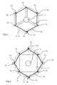
Figure 2 is a top view of a schematic representation of the offshore wind unit offigure 1 , -
Figure 3 is a top view of a schematic representation of an offshore wind unit according to a second embodiment of the present invention, -
Figure 4 is a top view of a schematic representation of an offshore wind unit according to a third embodiment of the present invention. -
Figure 1 shows afloating structure 3. Thisfloating structure 3 could be designed to receive awind turbine 4 or other structures like for example an electrical sub-station for a wind farm. Thefloating structure 3 comprises a tensionedmooring system 5 intended to moor and stabilize thefloating structure 3 to the seabed Sb. Thefloating structure 3 floats preferably between two waters under the sea-level SI. - The tensioned mooring system (5) comprises at least three
independent anchors 53 disposed on the seabed Sb and at least twotendons 52 peranchors 53 linked to thefloating structure 3. Eachtendon 52 of thesame anchor 53 has adifferent junction point 31 with thefloating structure 3. This configuration causes thetendons 52 of thesame anchor 53 to be inclined on either side of a vertical plane C linking theanchor 53 and the center of thefloating structure 3,. - The
tendon 52 could be for example a metallic cable or a synthetic rope linking ajunction point 31 to amooring point 51 on theanchor 53. Thetendon 52 could also be a metallic chain attached to ajunction point 31 on thefloating structure 3 and to amooring point 51. Thetendons 52 are tensioned in order to limits the relative movements of thefloating structure 3. - The
anchors 53 could be for example steel piles driven into the seabed, drilled dans grouted piles into the seabed or other means used in the domain of offshore wind turbine like for example suctions buckets. Preferably theanchors 53 are permanently sealed on the seabed Sb to ensure the stability and mooring of thefloating structure 3. - As shown in
figure 2 , thejunction points 31 of thetendons 52 on thefloating structure 3 are disposed on an inner virtual circle A. The center of this inner virtual circle A is preferably the relative center of thefloating structure 3, for example where the mast of theturbine 4 is intended to be disposed. - The
tendons 52 are attached to theanchors 53 on mooring points 51. These mooring points 51 are disposed on an outer virtual circle B, coaxial with the inner virtual circle A. The diameter of the outer virtual circle B could be larger than (seefigure 2 ) or equal (seefigure 3 ) to the diameter of the inner virtual circle A. - This mooring configuration allows having a great stability of the floating
structure 3 notably concerning the pitch or roll movements of the floatingstructure 3. Furthermore, by using a limited number oftendons 52, the costs remain controlled and reduced. - If the outer virtual circle B has a larger diameter than the inner virtual circle A, as shown in
figure 2 , thetendons 52 directed downwards, laterally and outwards from theirjunction points 31 as they descend towards theirmooring points 51 and also outwards from the vertical under the floatingstructure 3 as they descend towards their mooring points 51. This configuration is particularly advantageous in order to increase even more the stability of the floating structure. - If the outer virtual circle B and the inner virtual circle A have an equal diameter, as shown in
figure 3 , thetendons 52 are directed downwards and laterally (along a virtual cylinder associated with the virtual circles A, B) under theirjunction points 31 as they descend towards their mooring points 51. - The diameter of the outer virtual circle B is calculated in order to have an optimum between the angle of inclination, the tension and the length of the
tendons 52. This configuration allows to reduce the costs by limiting the length of thetendons 52. - Two
adjacent tendons 52 of twoadjacent anchors 53 may have acommon junction point 31 with the floatingstructure 3. Bycommon junction point 31, we mean that the junction points 31 of theseadjacent tendons 52 of twoadjacent anchors 53 are disposed in the same area of the floatingstructure 3 and only separated by a minimal distance induced by the assembly constraints. - Two
tendons 52 of asame anchor 53 may have the same inclination with the vertical virtual plane C linking themooring point 51 and the center of the floating structure, as shown infigure 1 . This allows to have a balanced tension of thesetendons 52 and of the floatingstructure 3 in general. Theanchor 53 is then disposed on the seabed at equidistance of the twoadjacent junction points 31 these twotendons 52 are attached to. - In order to have a good stability of the floating
structure 3 in general, the mooring points 51 of thetendons 52 and theanchors 53 have preferably a regular distribution on the outer virtual circle B as shown infigures 2 and3 . - Also, in order to have a good stability of the floating
structure 3 in general, the junction points 31 of thetendons 52 on the floatingstructure 3 have preferably a regular distribution on the inner virtual circle A. - In the examples of
figures 1 to 3 , the floatingstructure 3 has a triangular shape and comprises only threejunction points 31 and in consequence three anchors 53. It is also possible to imagine a floatingstructure 3 having a different shape withmore junction points 31,more anchors 53 and alsomore tendons 52. Thefigure 4 shows for example a square shaped floatingstructure 3 having fourjunction points 31 respectively at the corners of the square and four anchors 53. Other shapes are also possible. - The present invention also concerns an installation method of a floating
structure 3 designed to receive awind turbine 4. - This installation method comprises a first step of disposal of at least three
anchors 53 on the seabed Sb and attaching at least twotendons 52 to eachanchor 53 on dedicated mooring points 51. As mentioned above, the mooring points 51 are disposed on an outer virtual circle B. As mentioned above, the center of the outer virtual circle B is preferably the relative center of the floatingstructure 3, for example where the mast of theturbine 4 will be disposed. If thetendons 52 are for example metallic chains or metallic cables, it is possible to let them rest directly on the seabed Sb while waiting for the next steps of the installation method. If thetendons 52 are for example synthetic cables, a submerged buoy can be used to prevent thetendons 52 to rest directly on the seabed Sb while waiting for the next steps of the installation method. - During this first step of disposal of the
anchors 53 on the seabed Sb, theanchors 53 are advantageously permanently sealed on the seabed Sb. - Still during this first step, the
anchors 53 may be disposed in order that the mooring points 51 are disposed on the outer virtual circle B in a regular distribution. - The installation method comprises a second step of towing the floating
structure 3 on site above theanchors 51 location. - This installation method comprises a third step of connection of the
tendons 52 to the floatingstructure 3 on their dedicated junction points 31. As mentioned above, the junction points 31 are disposed on an inner virtual circle A coaxial with the outer virtual circle B. The inner virtual circle A has a smaller or equal diameter than the outer virtual circle B. - During this third step, the
tendons 52 are also tensioned. Different methods to tense thetendons 52 are possible. - A first method could be to link firstly the
tendons 52 to the floatingstructure 3 on theirjunction points 31 and then to tense thetendons 52 by known means. - A second method could be to sink the floating
structure 3, for example with ballasts, to a first depth in order to link thetendons 52. After thetendons 52 are linked, the floatingstructure 3 is raised to a shallower depth, for example by emptying the ballasts, tensioning thetendons 52. - During this third step, two
adjacent tendons 52 of twoadjacent anchors 53 may have acommon junction point 31 with the floatingstructure 3. The junction points 31 of thetendons 52 of asame anchor 53 may also be disposed on the floatingstructure 3 so that twotendons 52 of asame anchor 53 have the same inclination with the vertical virtual plane C linking themooring point 51 and the center of the floatingstructure 3. - Still during this third step, two
tendons 52 of asame anchor 53 may be disposed in order to have an angle with respect to each other of maximum 45° after connection on the floatingstructure 3. The junction points 31 of thetendons 52 on the floatingstructure 3 may also be disposed on the inner virtual circle A in a regular distribution.
Claims (13)
- Floating structure (3) comprising a tensioned mooring system (5) intended to moor and stabilize the floating structure (3) to the seabed (Sb), preferably for an offshore wind turbine,wherein the tensioned mooring system (5) comprises at least three independent anchors (53) disposed on the seabed (Sb) and at least two tendons (52) per anchors (53) linked to the floating structure (3), each tendon (52) of the same anchor (53) having a different junction point (31) with -the floating structure (3) so that the tendons (52) of the same anchor (53) are inclined on either side of a vertical plane (C) linking the anchor (53) and the center of the floating structure (3), the junction points (31) of the tendons (52) on the floating structure (3) being disposed on an inner virtual circle (A),and wherein the tendons (52) are attached to the anchors (53) on mooring points (51) disposed on an outer virtual circle (B) coaxial with the inner virtual circle (A) and having a larger or equal diameter than the inner virtual circle (A).
- Floating structure (3) according to claim 1, wherein two adjacent tendons (52) of two adjacent anchors (53) have a common junction point (31) on the floating structure (3).
- Floating structure (3) according to anyone of the preceding claims, wherein the two tendons (52) of a same anchor (53) have the same inclination with the vertical virtual plane (C) linking the mooring point (51) and the center of the floating structure (3).
- Floating structure (3) according to anyone of the preceding claims, wherein the mooring points (51) have a regular distribution on the outer virtual circle (B).
- Floating structure (3) according to anyone of the preceding claims, wherein the junction points (31) of the tendons (52) on the floating structure (3) have a regular distribution on the inner virtual circle (A).
- Floating structure (3) according to anyone of the preceding claims, wherein the anchors (53) are permanently sealed on the seabed (Sb).
- Installation method of a floating structure (3), preferably for an offshore wind turbine, said method comprising the steps:- disposing of at least three anchors (53) on the seabed (Sb) and attachment of at least two tendons (52) to each anchor (53) on dedicated mooring points (51), said mooring points (51) being disposed on an outer virtual circle (B),- towing of the floating structure (3) on site above the anchors (51) location,- connection of the tendons (52) to the floating structure (3) on dedicated junction points (31) and tensioning the tendons (52), said junction points (31) being disposed on an inner virtual circle (A) coaxial with the outer virtual circle (B) and having a smaller or equal diameter than the outer virtual circle (B).
- Installation method according to claim 7, wherein two adjacent tendons (52) of two adjacent anchors (53) have a common junction point (31) with the floating structure (3).
- Installation method according to anyone claims 7 or 8, wherein the junction points (31) of the tendons (52) of a same anchor (53) are disposed on the floating structure (3) so that two tendons (52) of a same anchor (53) have the same inclination with a vertical virtual plane (C) linking the mooring point (51) and the center of the floating structure (3).
- Installation method according to anyone of the claims 7 to 9, wherein the two tendons (52) of a same anchor (53) have an angle with respect to each other of maximum 45° after connection on the floating structure (3).
- Installation method according to anyone of claims 7 to 10, wherein the mooring points (51) are disposed on the outer virtual circle (B) in a regular distribution.
- Installation method according to anyone of claims 7 to 11, wherein the junction points (31) of the tendons (52) on the floating structure (3) are disposed on the inner virtual circle (A) in a regular distribution.
- Installation method according to anyone of claims 7 to 12, wherein the anchors (53) are permanently sealed on the seabed (Sb) during the step of disposal of the anchors (53) on the seabed (Sb).
Priority Applications (3)
| Application Number | Priority Date | Filing Date | Title |
|---|---|---|---|
| EP22315349.5A EP4389582A1 (en) | 2022-12-22 | 2022-12-22 | Floating structure and mooring system for an offshore wind turbine |
| PCT/EP2023/086080 WO2024132939A1 (en) | 2022-12-22 | 2023-12-15 | Floating structure and mooring system for an offshore wind turbine |
| JP2025533632A JP2025540350A (en) | 2022-12-22 | 2023-12-15 | Floating structures and mooring systems for offshore wind turbines |
Applications Claiming Priority (1)
| Application Number | Priority Date | Filing Date | Title |
|---|---|---|---|
| EP22315349.5A EP4389582A1 (en) | 2022-12-22 | 2022-12-22 | Floating structure and mooring system for an offshore wind turbine |
Publications (1)
| Publication Number | Publication Date |
|---|---|
| EP4389582A1 true EP4389582A1 (en) | 2024-06-26 |
Family
ID=84982605
Family Applications (1)
| Application Number | Title | Priority Date | Filing Date |
|---|---|---|---|
| EP22315349.5A Withdrawn EP4389582A1 (en) | 2022-12-22 | 2022-12-22 | Floating structure and mooring system for an offshore wind turbine |
Country Status (3)
| Country | Link |
|---|---|
| EP (1) | EP4389582A1 (en) |
| JP (1) | JP2025540350A (en) |
| WO (1) | WO2024132939A1 (en) |
Citations (2)
| Publication number | Priority date | Publication date | Assignee | Title |
|---|---|---|---|---|
| US20110107953A1 (en) * | 2009-10-16 | 2011-05-12 | Jaehnig Jens | Floating Platform with Improved Anchoring |
| CN112032002A (en) * | 2020-08-03 | 2020-12-04 | 广东工业大学 | Offshore wind power generation system and adjusting method |
-
2022
- 2022-12-22 EP EP22315349.5A patent/EP4389582A1/en not_active Withdrawn
-
2023
- 2023-12-15 JP JP2025533632A patent/JP2025540350A/en active Pending
- 2023-12-15 WO PCT/EP2023/086080 patent/WO2024132939A1/en not_active Ceased
Patent Citations (2)
| Publication number | Priority date | Publication date | Assignee | Title |
|---|---|---|---|---|
| US20110107953A1 (en) * | 2009-10-16 | 2011-05-12 | Jaehnig Jens | Floating Platform with Improved Anchoring |
| CN112032002A (en) * | 2020-08-03 | 2020-12-04 | 广东工业大学 | Offshore wind power generation system and adjusting method |
Also Published As
| Publication number | Publication date |
|---|---|
| JP2025540350A (en) | 2025-12-11 |
| WO2024132939A1 (en) | 2024-06-27 |
Similar Documents
| Publication | Publication Date | Title |
|---|---|---|
| EP3430259B1 (en) | A floating wind turbine and a method for the installation of such floating wind turbine | |
| KR102645773B1 (en) | Floating wind turbine assembly and method for mooring the floating wind turbine assembly | |
| KR102144423B1 (en) | Semi-submergible type wind power generator and its installation and decomission method | |
| NO345344B1 (en) | Floating wind turbine platform | |
| CN210653580U (en) | Offshore wind power platform group with shared mooring | |
| US12442359B2 (en) | Windmill construction and a method for assembly of a windmill construction | |
| EP1346154A1 (en) | Mast construction and erection method for offshore installation | |
| WO2022098288A1 (en) | Mooring system comprising buoys and anchors | |
| NO20200826A1 (en) | A mooring system for a plurality of floating units | |
| US20220063774A1 (en) | Offshore semi-submersible platform for supporting a wind turbine and offshore electrical energy production facility | |
| JP2014510665A (en) | Buoyancy device with special mooring system | |
| KR102144424B1 (en) | Tension-leg platform type wind power generator and its installation and decomission method | |
| WO2022098246A1 (en) | Installing offshore floating wind turbines | |
| GB2327970A (en) | Method of installing a tower | |
| CN116812075B (en) | A floating monopole wind turbine platform mooring system | |
| CN210653579U (en) | Offshore wind power platform group sharing mooring point | |
| SE545666C2 (en) | Mooring System | |
| EP4389581A1 (en) | Floating structure and mooring system for an offshore wind turbine | |
| WO2024132939A1 (en) | Floating structure and mooring system for an offshore wind turbine | |
| KR102062204B1 (en) | Method for All-in-one Installation and Transportation of Offshore Wind Turbine | |
| CN218594530U (en) | Floating offshore wind turbine floating body and steel bearing platform stress construction structure | |
| EP3587238A1 (en) | Tension leg platform | |
| KR20250101971A (en) | Offshore platform with vertical column assembly | |
| CN115535186A (en) | Integral installation construction method for floating type offshore wind turbine bearing platform base | |
| KR102922135B1 (en) | Detachable Spud Anchor |
Legal Events
| Date | Code | Title | Description |
|---|---|---|---|
| PUAI | Public reference made under article 153(3) epc to a published international application that has entered the european phase |
Free format text: ORIGINAL CODE: 0009012 |
|
| STAA | Information on the status of an ep patent application or granted ep patent |
Free format text: STATUS: THE APPLICATION HAS BEEN PUBLISHED |
|
| AK | Designated contracting states |
Kind code of ref document: A1 Designated state(s): AL AT BE BG CH CY CZ DE DK EE ES FI FR GB GR HR HU IE IS IT LI LT LU LV MC ME MK MT NL NO PL PT RO RS SE SI SK SM TR |
|
| STAA | Information on the status of an ep patent application or granted ep patent |
Free format text: STATUS: THE APPLICATION IS DEEMED TO BE WITHDRAWN |
|
| 18D | Application deemed to be withdrawn |
Effective date: 20250103 |