EP4389541A1 - Parking route generation device - Google Patents
Parking route generation device Download PDFInfo
- Publication number
- EP4389541A1 EP4389541A1 EP22869878.3A EP22869878A EP4389541A1 EP 4389541 A1 EP4389541 A1 EP 4389541A1 EP 22869878 A EP22869878 A EP 22869878A EP 4389541 A1 EP4389541 A1 EP 4389541A1
- Authority
- EP
- European Patent Office
- Prior art keywords
- route
- backward
- parking
- coupled vehicle
- trajectory
- Prior art date
- Legal status (The legal status is an assumption and is not a legal conclusion. Google has not performed a legal analysis and makes no representation as to the accuracy of the status listed.)
- Pending
Links
Images


Classifications
-
- G—PHYSICS
- G08—SIGNALLING
- G08G—TRAFFIC CONTROL SYSTEMS
- G08G1/00—Traffic control systems for road vehicles
- G08G1/16—Anti-collision systems
-
- G—PHYSICS
- G08—SIGNALLING
- G08G—TRAFFIC CONTROL SYSTEMS
- G08G1/00—Traffic control systems for road vehicles
- G08G1/16—Anti-collision systems
- G08G1/168—Driving aids for parking, e.g. acoustic or visual feedback on parking space
-
- B—PERFORMING OPERATIONS; TRANSPORTING
- B60—VEHICLES IN GENERAL
- B60W—CONJOINT CONTROL OF VEHICLE SUB-UNITS OF DIFFERENT TYPE OR DIFFERENT FUNCTION; CONTROL SYSTEMS SPECIALLY ADAPTED FOR HYBRID VEHICLES; ROAD VEHICLE DRIVE CONTROL SYSTEMS FOR PURPOSES NOT RELATED TO THE CONTROL OF A PARTICULAR SUB-UNIT
- B60W30/00—Purposes of road vehicle drive control systems not related to the control of a particular sub-unit, e.g. of systems using conjoint control of vehicle sub-units
- B60W30/06—Automatic manoeuvring for parking
-
- B—PERFORMING OPERATIONS; TRANSPORTING
- B60—VEHICLES IN GENERAL
- B60W—CONJOINT CONTROL OF VEHICLE SUB-UNITS OF DIFFERENT TYPE OR DIFFERENT FUNCTION; CONTROL SYSTEMS SPECIALLY ADAPTED FOR HYBRID VEHICLES; ROAD VEHICLE DRIVE CONTROL SYSTEMS FOR PURPOSES NOT RELATED TO THE CONTROL OF A PARTICULAR SUB-UNIT
- B60W60/00—Drive control systems specially adapted for autonomous road vehicles
- B60W60/001—Planning or execution of driving tasks
- B60W60/0011—Planning or execution of driving tasks involving control alternatives for a single driving scenario, e.g. planning several paths to avoid obstacles
-
- B—PERFORMING OPERATIONS; TRANSPORTING
- B62—LAND VEHICLES FOR TRAVELLING OTHERWISE THAN ON RAILS
- B62D—MOTOR VEHICLES; TRAILERS
- B62D15/00—Steering not otherwise provided for
- B62D15/02—Steering position indicators ; Steering position determination; Steering aids
- B62D15/027—Parking aids, e.g. instruction means
- B62D15/0285—Parking performed automatically
-
- G—PHYSICS
- G01—MEASURING; TESTING
- G01C—MEASURING DISTANCES, LEVELS OR BEARINGS; SURVEYING; NAVIGATION; GYROSCOPIC INSTRUMENTS; PHOTOGRAMMETRY OR VIDEOGRAMMETRY
- G01C21/00—Navigation; Navigational instruments not provided for in groups G01C1/00 - G01C19/00
- G01C21/26—Navigation; Navigational instruments not provided for in groups G01C1/00 - G01C19/00 specially adapted for navigation in a road network
- G01C21/34—Route searching; Route guidance
- G01C21/36—Input/output arrangements for on-board computers
- G01C21/3605—Destination input or retrieval
- G01C21/3614—Destination input or retrieval through interaction with a road map, e.g. selecting a POI icon on a road map
-
- G—PHYSICS
- G05—CONTROLLING; REGULATING
- G05D—SYSTEMS FOR CONTROLLING OR REGULATING NON-ELECTRIC VARIABLES
- G05D1/00—Control of position, course, altitude or attitude of land, water, air or space vehicles, e.g. using automatic pilots
- G05D1/40—Control within particular dimensions
- G05D1/43—Control of position or course in two dimensions [2D]
-
- B—PERFORMING OPERATIONS; TRANSPORTING
- B60—VEHICLES IN GENERAL
- B60W—CONJOINT CONTROL OF VEHICLE SUB-UNITS OF DIFFERENT TYPE OR DIFFERENT FUNCTION; CONTROL SYSTEMS SPECIALLY ADAPTED FOR HYBRID VEHICLES; ROAD VEHICLE DRIVE CONTROL SYSTEMS FOR PURPOSES NOT RELATED TO THE CONTROL OF A PARTICULAR SUB-UNIT
- B60W2720/00—Output or target parameters relating to overall vehicle dynamics
- B60W2720/10—Longitudinal speed
Definitions
- One aspect of the present invention relates to a parking route generation device.
- Patent Literature 1 describes a backward parking assistance device that assists with backward parking of a coupled vehicle including a tractor and a trailer.
- the backward parking assistance device described in Patent Literature 1 creates a parking target route from a host vehicle position to a target parking position, and sets a steering angle of the coupled vehicle so that the coupled vehicle moves along the parking target route.
- a traveling trajectory of the coupled vehicle when follow-up control is performed using a Pure Pursuit method is created for the parking target route.
- Patent Literature 1 Japanese Unexamined Patent Publication No. 2018-199458
- One aspect of the present invention has been made in view of these circumstances, and an object of the present invention is to generate a parking route for a coupled vehicle with high accuracy and at a low calculation cost.
- a parking route generation device for generating a parking route for causing a coupled vehicle including a tractor and a trailer to park
- the parking route generation device including: a pattern storage unit configured to store a plurality of backward route patterns with a rear axle of the trailer as a reference for each wheelbase type of the trailer, the plurality of backward route patterns being a plurality of backward route patterns having different degrees of change in curvature in the route; a position setting unit configured to set a parking start position of the coupled vehicle and a target parking position of the coupled vehicle on the basis of information including a current position of the coupled vehicle; a trajectory generation unit configured to specify the plurality of backward route patterns corresponding to a wheelbase type of the trailer in the coupled vehicle on the basis of information indicating the wheelbase type of the trailer in the coupled vehicle and information stored in the pattern storage unit, and generate a plurality of backward route profiles on the basis of the plurality of specified backward route patterns; a trajectory selection unit configured to select the
- the plurality of backward route patterns with a rear axle of the trailer as a reference are stored for each wheelbase type of the trailer in advance.
- the plurality of backward trajectory profiles corresponding to the wheelbase type of the trailer in the coupled vehicle are specified, and the plurality of backward trajectory profiles are generated on the basis of the plurality of specified backward trajectory profiles.
- the backward trajectory profile in which the coupled vehicle does not collide with a nearby obstacle is selected from among the plurality of backward trajectory profiles generated in this way, and the parking route is determined on the basis of the selected backward trajectory profile, the parking start position, and the target parking position.
- movement is particularly complex at the time of backward movement.
- the parking route generation device since the plurality of backward route patterns are stored for each wheelbase type of the trailer in advance, and the backward route profile is selected from among such information stored in advance, it is possible to greatly reduce the calculation cost. Further, since the plurality of backward route patterns are stored for each wheelbase length of the trailer, it is possible to generate the backward route with high precision (with high reproducibility) depending on the type of trailer to be coupled to the tractor. As described above, with the parking route generation device according to the aspect of the present embodiment, it is possible to generate the parking route for the coupled vehicle with high accuracy and at a low calculation cost.
- the route determination unit may determine a backward movement start position at which the coupled vehicle starts the backward movement, on the basis of the target parking position and the backward trajectory profile selected by the trajectory selection unit, determine, as the backward route, a route to reach the target parking position along the selected backward trajectory profile from the backward movement start position, determine a forward route in which the coupled vehicle that has started forward movement from the parking start position reaches the backward movement start position without collision with the obstacle, on the basis of the parking start position, the backward movement start position, and the information on the obstacle, after determining the backward route, and determine the parking route on the basis of the forward route and the backward route.
- the forward route is determined first and then the backward route is determined in an order of actual traveling routes
- there may be restrictions regarding the forward route in determining the backward route and for example, a vehicle posture may be bent at a point in time when the target parking position is reached.
- a problem occurs more noticeably in the coupled vehicle having a coupling angle.
- the backward route is determined first and then the forward route is determined (the route determination is made in reverse order from the target parking position), there are no restrictions regarding the forward route when the backward route is determined, making it possible to generate an ideal parking route by curbing bending of the vehicle posture at the time of parking.
- the route determination unit may determine the parking route on the basis of one backward trajectory profile having a lowest degree of change in curvature in the route among the plurality of backward trajectory profiles in which the coupled vehicle does not collide with the obstacle. Accordingly, since a route in which the number of steering wheel operations is as small as possible is selected for the backward route, it is possible to curb a driver's discomfort at the time of backward movement.
- FIG. 1 is a block diagram schematically illustrating a parking control device including a parking route generation device according to an embodiment of the present invention.
- the parking control device 1 according to the present embodiment is a device that automatically causes a coupled vehicle 2 to park in a parking lot or the like, as illustrated in FIGS. 2 and 3 .
- the coupled vehicle 2 is a large semi-trailer truck.
- the coupled vehicle 2 may be a medium-sized truck or a small-sized truck.
- the coupled vehicle 2 includes a tractor 3 and a trailer 4 disposed on the rear side of the tractor 3.
- the trailer 4 is rotatably coupled to the tractor 3 at a coupling portion 5.
- the tractor 3 includes a vehicle body 6, a pair of left and right front wheels 7 rotatably supported on the front side of the vehicle body 6, and a pair of left and right rear wheels 8 rotatably supported on the rear side of the vehicle body 6.
- the tractor 3 has an engine (not illustrated) mounted thereon.
- the trailer 4 includes a vehicle body 9 and a pair of left and right wheels 10 rotatably supported on the rear side of the vehicle body 9.
- the parking control device 1 is mounted on the tractor 3 of the coupled vehicle 2.
- the parking control device 1 includes a car navigation 11, a coupling angle sensor 12, a camera 13, a route generation ECU 14, and a parking control ECU 15.
- the car navigation 11, the coupling angle sensor 12, the camera 13, and the route generation ECU 14 constitute a parking route generation device 16 of the present embodiment.
- the parking route generation device 16 is a device that generates a parking route for causing the parking control device 1 to park the coupled vehicle 2.
- the parking route generation device 16 generates a parking route in which the coupled vehicle 2 moves forward from the side of a parking space H, turns around once, and then moves backward into the parking space H. Specifically, the parking route generation device 16 generates a parking route in which the coupled vehicle 2 moves forward from a parking start position A1 to a turnaround position A3 (backward movement start position) and then moves backward from the turnaround position A3 to the target parking position A2.
- the parking start position A1, the target parking position A2, and the turnaround position A3 will be described in detail below.
- the car navigation 11 includes a GPS receiver 17 that receives radio waves transmitted from GPS satellites and measures the current position of the coupled vehicle 2, a map storage unit 18 that stores map data, a display 19 that displays the current position of the coupled vehicle 2 together with the map, and an input unit 20 that sets and inputs data such as a destination of the coupled vehicle 2.
- the GPS receiver 17 constitutes a position detection unit that detects the current position of the coupled vehicle 2.
- the GPS receiver 17 detects position coordinates and an azimuth angle of two-dimensional coordinates (X and Y coordinates) of the tractor 3 as the current position of the coupled vehicle 2.
- the coupling angle sensor 12 is a sensor that detects a coupling angle between the tractor 3 and the trailer 4.
- the coupling angle is an angle at which an imaginary line extending in a front-rear direction of the tractor 3 intersects with an imaginary line extending in a front-rear direction of the trailer 4.
- the coupling angle is 0 degrees in a state in which the tractor 3 and the trailer 4 are disposed on the same straight line.
- the camera 13 is an imaging unit that images surroundings of the coupled vehicle 2.
- the camera 13 is provided, for example, in each of the tractor 3 and the trailer 4.
- the camera 13 constitutes an environment detection unit that detects a surrounding environment of the coupled vehicle 2, such as the presence or absence of an obstacle 50 ( FIG. 3 ).
- Examples of the obstacle 50 may include another parked vehicle 51 (see FIG. 3 or the like), a wall 52 of a building (see FIG. 7 or the like), and a curb.
- the map storage unit 18 of the car navigation 11 also constitutes the environment detection unit described above.
- the route generation ECU 14 includes a CPU, a RAM, a ROM, an input and output interface, and the like.
- the route generation ECU 14 receives information of the car navigation 11, a detection value of the coupling angle sensor 12, and a captured image of the camera 13, executes processing regarding generation of a parking route for the coupled vehicle 2, and outputs data including the parking route for the coupled vehicle 2 to the parking control ECU 15.
- the route generation ECU 14 includes a pattern storage unit 21, a position setting unit 22, a trajectory generation unit 23, a trajectory selection unit 24, a route determination unit 25, and a route output unit 26.
- the pattern storage unit 21 stores the plurality of backward route patterns with a rear axle of the trailer 4 as a reference for each wheelbase length (wheelbase type) of the trailer 4.
- the pattern storage unit 21 groups, for example, a plurality of types of trailers 4 that can be coupled to the tractor 3 for a predetermined range of wheelbase lengths, and stores the plurality of backward route patterns for each group.
- the pattern storage unit 21 divides the trailers 4, for example, into a group of trailers 4 having a wheelbase length of 6 m or less, a group of trailers 4 having a wheelbase length of more than 6 m and 8 m or less, and a group of trailers 4 having a wheelbase length of more than 8 m and 10 m or less, and stores the plurality of backward route patterns for each group.
- Each of the plurality of backward route patterns is a trajectory that the rear axle of the trailer 4 having the corresponding wheelbase length can actually take at the time of backward movement.
- the trajectory of the backward route pattern is represented by a curved line whose curvature changes continuously.
- the backward route pattern is a backward trajectory profile at a rear axle center of the trailer 4 when the coupled vehicle 2 turns in a most space-saving manner.
- the plurality of backward route patterns belonging to the group having the same wheelbase length have different degrees of change in curvature in the route.
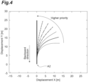
- the backward route pattern indicates the plurality of backward route patterns belonging to the group having the same wheelbase length, and seven backward route patterns having different degrees of change in curvature in the route are indicated as backward route patterns toward a common target parking position A2.
- the backward route pattern is illustrated in 15° increments in a range of 0° to 90° with the target parking position A2 as a reference.
- the backward route pattern is more likely to be selected in trajectory selection that will be described below, that is, the priority may be higher.
- a plurality of different backward route patterns are different.
- the parking route generation device 16 it is possible to generate the backward route with high precision (high reproducibility) since the backward route is generated on the basis of a backward route pattern close to an actual wheelbase length of the trailer 4.
- a tri-clothoid for example, is used for design of the backward route pattern.
- the backward route pattern is generated by off-line calculation, the backward route pattern may be generated by using a scheme with a higher load than the tri-clothoid.
- the position setting unit 22 sets the parking start position A1 of the coupled vehicle 2 and the target parking position A2 of the coupled vehicle 2 on the basis of information including the current position of the coupled vehicle 2.
- the position setting unit 22 uses the current position of the coupled vehicle 2 detected by the GPS receiver 17 of the car navigation 11 to set the parking start position A1 (see FIG. 3 ) of the coupled vehicle 2.
- the position setting unit 22 sets the parking start position A1 of the coupled vehicle 2 on the basis of the current position of the coupled vehicle 2 and the coupling angle ⁇ between the tractor 3 and the trailer 4 detected by the coupling angle sensor 12.
- the position setting unit 22 acquires, for example, position coordinates, an azimuth angle, and a turning curvature of the trailer 4 as the parking start position A1 of the coupled vehicle 2.
- the position setting unit 22 sets the target parking position A2 (see FIG. 3 ) of the coupled vehicle 2 using the information of the car navigation 11 including the current position of the coupled vehicle 2 detected by the GPS receiver 17. Specifically, the position setting unit 22 sets the target parking position A2 of the coupled vehicle 2 on the basis of information of the car navigation 11 including the current position of the coupled vehicle 2, the coupling angle ⁇ between the tractor 3 and the trailer 4 detected by the coupling angle sensor 12, and the captured image of the camera 13.
- the target parking position A2 may be input as coordinate information from the outside of the present system according to an external instruction (an HMI operation by the driver, an instruction from a traffic control, or the like), autonomous parking space detection in an upper processing layer of an automatic driving system, or the like.
- the position setting unit 22 acquires, for example, the position coordinates, azimuth angle, and turning curvature of the trailer 4 as the target parking position A2 of the coupled vehicle 2. Details of the processing of the position setting unit 22 will be described below.
- the trajectory generation unit 23 generates the plurality of backward trajectory profiles.
- the trajectory generation unit 23 specifies the plurality of backward route patterns corresponding to the wheelbase length of the trailer 4 in the coupled vehicle 2 on the basis of information indicating the wheelbase length of the trailer 4 in the coupled vehicle 2, and information stored in the pattern storage unit 21 (the plurality of backward route patterns for each wheelbase length of the trailer 4). That is, the trajectory generation unit 23 specifies the plurality of backward route patterns corresponding to the wheelbase length of the trailer 4 that is a target for which backward trajectory profiles are to be generated.
- Information such as the wheelbase length of the trailer 4 may be acquired, for example, by causing the trailer 4 to include an ID tag and reading the ID tag, or may also be estimated by image processing by the wheels being imaged by a camera mounted on the tractor 3 side.
- the plurality of backward route patterns illustrated in FIG. 5(b) are specified (extracted).
- the trajectory generation unit 23 generates the plurality of backward trajectory profiles on the basis of the plurality of specified backward route patterns.
- the trajectory generation unit 23 generates the backward trajectory profile (tractor backward trajectories) indicating a backward trajectory of the tractor 3 from the plurality of backward trajectory profiles with the rear axle of the trailer 4 as a reference. Details of processing of the trajectory generation unit 23 will be described below.
- the trajectory selection unit 24 selects a backward trajectory profile in which the coupled vehicle 2 does not collide with an obstacle, on the basis of the target parking position A2, information on the obstacle 50 around the coupled vehicle 2, and the plurality of backward trajectory profiles (tractor backward trajectories) generated by the trajectory generation unit 23.
- the information on the obstacle 50 around the coupled vehicle 2 is acquired from the camera 13 that can function as the environment detection unit and the map storage unit 18 of the car navigation 11.
- the trajectory selection unit 24 selects one or more backward trajectory profiles in which the trajectory does not overlap the obstacle 50 (that is, the vehicle body 9 of the trailer 4 or the vehicle body 6 of the tractor 3 does not collide with the objects 50) from among the plurality of backward trajectory profiles (tractor backward trajectories) leading to the target parking position A2. Details of the processing of the trajectory selection unit 24 will be described below.
- the route determination unit 25 determines the parking route so that the coupled vehicle 2 that has started parking from the parking start position A1 is parked at the target parking position A2 through backward movement after forward movement, on the basis of the target parking position A2 and the backward trajectory profile selected by the trajectory selection unit 24.
- the route determination unit 25 first determines the turnaround position A3 (backward movement start position) at which the coupled vehicle 2 starts backward movement, on the basis of the target parking position A2 and the backward trajectory profile selected by the trajectory selection unit 24.
- the route determination unit 25 determines, as the backward route, a route from the turnaround position A3 to the target parking position A2 along the selected backward trajectory profile.
- the route determination unit 25 determines the forward route in which the coupled vehicle 2 that has started forward movement from the parking start position A1 reaches the turnaround position A3 without collision with the obstacle 50, on the basis of the parking start position A1, the turnaround position A3, and the information on the obstacle 50.
- the route determination unit 25 determines the parking route by collating the forward route with the backward route.
- the route determination unit 25 determines the turnaround position A3 for each of the backward trajectory profiles, and determines the backward route and the forward route.
- the route determination unit 25 may determine the backward route of the parking route on the basis of one backward trajectory profile having a lowest degree of change in curvature in the route among the plurality of backward trajectory profiles.
- the route determination unit 25 uses a geometric model of the coupled vehicle 2 to perform a vehicle motion simulation in which the coupled vehicle 2 performs follow-up control through forward traveling from the parking start position A1 and the target parking position A2 to the turnaround position A3, to thereby calculate a data series of the steering angle of the tractor 3 and a data series of each posture angle of the tractor 3 and the trailer 4.
- the data series is history data.
- the route output unit 26 outputs data of the parking route (parking route data) determined by the route determination unit 25 to the parking control ECU 15. Further, the route output unit 26 outputs the data series of the steering angle of the tractor 3 and the data series of each posture angle of the tractor 3 and the trailer 4 to the parking control ECU 15.
- the parking control ECU 15 includes a CPU, a RAM, a ROM, an input and output interface, and the like.
- the parking control ECU 15 receives the parking route data and data series from the route generation ECU 14, the information from the car navigation 11, and the detection value from the coupling angle sensor 12, and executes processing regarding automatic parking of the coupled vehicle 2.
- the parking control ECU 15 includes a storage unit 31 and a follow-up control unit 32.
- the storage unit 31 stores the parking route data and the data series output from the route output unit 26 of the route generation ECU 14.
- the follow-up control unit 32 performs steering control and speed control of the coupled vehicle 2 to park the coupled vehicle 2 at the target parking position A2 according to the parking route data and data series stored in the storage unit 31.
- the follow-up control unit 32 controls the steering of the coupled vehicle 2 in the steering control of the coupled vehicle 2, and controls an accelerator and a brake in the speed control of the coupled vehicle 2.
- the follow-up control unit 32 performs feedforward control of steering of the tractor 3 to park the coupled vehicle 2 at the target parking position A2, according to the data series of the steering angle of the tractor 3 and the data series of each of posture angles of the tractor 3 and the trailer 4. That is, the follow-up control unit 32 performs feedforward control of the steering of the tractor 3 with the data series of the steering angle of the tractor 3 and the data series of each posture angle of the tractor 3 and the trailer 4 as target values.
- the follow-up control unit 32 performs feedback control of the steering of the tractor 3 so that the coupled vehicle 2 is parked at the target parking position A2, on the basis of the coupling angle ⁇ between the tractor 3 and the trailer 4 detected by the coupling angle sensor 12 and the current position of the coupled vehicle 2 detected by the GPS receiver 17.
- the follow-up control unit 32 performs, for example, follow-up control for virtually considering a vehicle in a target posture on a target route of the trailer 4 given by a tri-clothoid curve and making a relative error of an actual vehicle with respect to the target value close to 0 as a state quantity.
- An example of the follow-up control for making an error state quantity close to 0 may include LQ control.
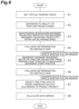
- FIG. 6 is a flowchart illustrating details of the procedure of the route generation process executed by the route generation ECU 14. This process is executed when a driver of the coupled vehicle 2 instructs to start parking assistance. In this case, the driver may set and input a target parking position candidate for the coupled vehicle 2 using the input unit 20 of the car navigation 11.
- the route generation ECU 14 sets a virtual parking space at the target parking position A2 (step S1).
- the route generation ECU 14 first acquires the position coordinates, azimuth angle, and turning curvature of the trailer 4 as the parking start position A1 of the coupled vehicle 2 on the basis of the information of the car navigation 11 including the GPS receiver 17 and the detection value of the coupling angle sensor 12.
- the position coordinates of the trailer 4 are, for example, position coordinates of the rear axle center of the trailer 4. As illustrated in FIG.
- the rear axle center of the trailer 4 is a center in an axial direction (a vehicle width direction of the trailer 4) of a vehicle axle 10a coupled to the pair of left and right wheels 10 disposed on the rear side of the trailer 4.
- the azimuth angle of the trailer 4 corresponds to a yaw angle of the trailer 4.
- the azimuth angle of the tractor 3 corresponds to a yaw angle of the tractor 3.
- the turning curvature of the trailer 4 uniquely corresponds to the coupling angle of the trailer 4 with respect to the tractor 3 on condition that steady turning of the coupled vehicle 2 is assumed. Therefore, the coupling angle ⁇ between the tractor 3 and the trailer 4 is obtained by using an algebraic formula with the turning curvature of the trailer 4 as an input.
- the turning curvature of the trailer 4 is obtained from the coupling angle ⁇ between the tractor 3 and the trailer 4.
- the route generation ECU 14 sets the position coordinates, azimuth angle, and turning curvature of the trailer 4 as the target parking position A2 of the coupled vehicle 2 on the basis of the information of the car navigation 11 including the GPS receiver 17, the detection value of the coupling angle sensor 12, and the captured image of the camera 13.
- the route generation ECU 14 sets virtual walls V1 to V3 constituting a virtual parking space that surrounds three sides of the target parking position A2.
- the virtual walls V1 and V2 are virtual walls that surround side surfaces of the coupled vehicle 2
- the virtual wall V3 is a virtual wall that surrounds a rear part of the coupled vehicle 2.
- the route generation ECU 14 sets a backward route to be described below so that the coupled vehicle 2 does not come into contact the virtual walls V1 to V3.
- the route generation ECU 14 generates the plurality of backward trajectory profiles (tractor backward trajectories) indicating the backward trajectories of the tractor 3 (step S2).
- the route generation ECU 14 first specifies the plurality of backward route patterns corresponding to the wheelbase length of the trailer 4 in the coupled vehicle 2 on the basis of the information indicating the wheelbase length of the trailer 4 in the coupled vehicle 2 and the information stored in the pattern storage unit 21 (the plurality of backward route patterns for each wheelbase length of the trailer 4). That is, the route generation ECU 14 specifies the plurality of backward route patterns corresponding to the wheelbase length of the trailer 4 that is a target for which backward trajectory profiles are to be generated (see an upper diagram in FIG. 8 ).
- Such a backward route pattern is generated by using a tri-clothoid curve as a curve on which a curvature changes continuously from an initial position to a target position.
- the tri-clothoid curve is a curve in which sudden change in curvature do not occur.
- the tri-clothoid curve is a smooth curve whose initial and end curves and positions can be arbitrarily designated through a combination of three clothoid curves with the same route lengths.
- the tri-clothoid curve can be simply obtained by numerically solving a 2-variable nonlinear equation.
- the tri-clothoid curve is described in detail in "Route generation scheme capable of designating initial and end curvatures using a clothoid curve" in the Transactions of the Japan Society of Mechanical Engineers (Vol. 85, No. 878, 2019).
- the route generation ECU 14 generates the plurality of backward trajectory profiles on the basis of the plurality of specified backward route patterns. Specifically, the route generation ECU 14 generates the backward trajectory profile (tractor backward trajectories) indicating the backward trajectories of the tractor 3 from the plurality of backward trajectory profiles with the rear axle of the trailer 4 as a reference.
- a trajectory of the rear axle of the trailer 4 is indicated by a solid line
- a trajectory of a rear axle of the tractor 3 is indicated by a broken line.
- the route generation ECU 14 derives the trajectory of the rear axle of the tractor 3 indicated by the broken line, on the basis of, for example, the trajectory of the rear axle of the trailer 4 indicated by the solid line and dimensions of the vehicle body 9 of the trailer 4.
- the route generation ECU 14 derives the trajectory of the entire coupled vehicle 2 on the basis of the trajectory of the rear axle of the trailer 4 and the trajectory of the rear axle of the tractor 3, as illustrated in a lower diagram in a lower part of FIG. 8 .
- the route generation ECU 14 generates the backward trajectory profile for each of the plurality of backward route patterns, as illustrated in a lower part of FIG. 8 .
- the route generation ECU 14 moves (adjusts) a position of each backward trajectory profile so that the backward trajectory profile fits within the virtual walls V1 to V3 constituting the virtual parking space (step S3).
- the backward trajectory profile is moved in a Y-axis (vertical) direction so that a position at which the coupled vehicle 2 does not collide with the virtual parking space is found.
- FIG. 9(a) is a diagram in which the backward trajectory profile has been greatly moved in a negative direction of a Y-axis
- FIG. 9(b) is a diagram in which the backward trajectory profile has been greatly moved in a positive direction of the Y-axis.
- the route generation ECU 14 uses, for example, a binary search method to set the backward trajectory profile at a position at which the coupled vehicle 2 does not collide with the virtual parking space and which is as close to the target parking position A2 as possible. As illustrated in FIG. 9(c) , once the position of the backward trajectory profile is determined, the route generation ECU 14 modifies the trajectory to add a straight section to a goal (the target parking position A2).
- the route generation ECU 14 performs a collision determination related to the backward route of the coupled vehicle 2 on the basis of the obstacle map (step S4).
- the obstacle map is information indicating the position of the obstacle 50 acquired from the camera 13 which can function as the environment detection unit and the map storage unit 18 of the car navigation 11.
- the route generation ECU 14 determines whether the vehicle collides with an obstacle 50 (whether the obstacle 50 exists on the trajectory) for the plurality of backward trajectory profiles (tractor backward trajectories) leading to the target parking position A2.
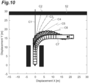
- backward trajectory profiles C1 to C3 among seven backward trajectory profiles C1 to C7 collide with the wall 52 of the building, which is the obstacle 50.
- the route generation ECU 14 leaves (selects) the backward trajectory profiles C4 to C7 other than the backward trajectory profiles C1 to C3 as candidate routes for the backward route.
- the route generation ECU 14 determines the turnaround position A3 (backward movement start position) at which the coupled vehicle 2 starts backward movement, on the basis of the target parking position A2 and the backward trajectory profile selected by the trajectory selection unit 24.
- the route generation ECU 14 generates a forward route of a tractor trajectory on the basis of the parking start position A1 and the turnaround position A3 (step S5).
- the route generation ECU 14 performs a collision determination related to the forward route of the coupled vehicle 2 on the basis of the obstacle map (step S6).
- the obstacle map is information indicating the position of the obstacle 50 acquired from the camera 13 which can function as the environment detection unit and the map storage unit 18 of the car navigation 11.
- the route generation ECU 14 determines whether a plurality of forward trajectory profiles (tractor forward trajectories) from the parking start position A1 to the turnaround position A3 collide with the obstacle 50 (whether the obstacle 50 is present on the trajectory). In the example illustrated in FIG. 11 , the forward trajectory profile does not collide with, for example, the wall 52 of the building, which is the obstacle 50.
- the route generation ECU 14 specifies candidate routes for the forward route.
- the route generation ECU 14 determines one final route from the candidate routes on the basis of a preset priority.
- the backward trajectory profiles C4 to C7 are selected as candidate routes for the backward route.
- the route generation ECU 14 determines, for example, the backward trajectory profile C4 having the lowest degree of change in curvature in the route among the plurality of backward trajectory profiles C4 to C7, as a final route of the backward route.
- the forward route is also determined to be a forward route that is continuous with the backward trajectory profile C4.
- the route generation ECU 14 uses the geometric model of the coupled vehicle 2 to perform a vehicle motion simulation in which the coupled vehicle 2 performs follow-up control through forward traveling from the parking start position A1 and the target parking position A2 to the turnaround position A3, to thereby calculate a data series of the steering angle of the tractor 3 and a data series of each posture angle of the tractor 3 and the trailer 4.
- the data series is history data.
- the parking route generation device 16 is a parking route generation device that generates a parking route for causing the coupled vehicle 2 including the tractor 3 and the trailer 4 to park, and includes the pattern storage unit 21 that stores the plurality of backward route patterns with the rear axle of the trailer 4 as a reference for each wheelbase length of the trailer 4, the plurality of backward route patterns being a plurality of backward route patterns having a different degree of change in curvature in the route; the position setting unit 22 that sets the parking start position A1 of the coupled vehicle 2 and the target parking position A2 of the coupled vehicle 2 on the basis of the information including the current position of the coupled vehicle 2; the trajectory generation unit 23 that specifies the plurality of backward route patterns corresponding to the wheelbase length of the trailer 4 in the coupled vehicle 2 on the basis of the information indicating the wheelbase length of the trailer 4 in the coupled vehicle 2 and the information stored in the pattern storage unit 21, and generates a plurality of backward route profiles on the basis of the plurality of specified backward route patterns; the trajectory selection unit 24 that
- the plurality of backward route patterns with the rear axle of the trailer 4 as a reference are stored for each wheelbase length of the trailer 4 in advance.
- the plurality of backward trajectory profiles corresponding to the wheelbase length of the trailer 4 in the coupled vehicle 2 are specified, and the plurality of backward trajectory profiles are generated on the basis of the plurality of specified backward trajectory profiles.
- the backward trajectory profile in which the coupled vehicle 2 does not collide with the surrounding obstacle 50 is selected from among the plurality of backward trajectory profiles generated in this way, and the parking route is determined on the basis of the selected backward trajectory profile, the parking start position A1, and the target parking position A2.
- the parking route generation device 16 since the plurality of backward route patterns are stored for each wheelbase length of the trailer 4 in advance, and the backward route profile is selected from among such information stored in advance, it is possible to greatly reduce the calculation cost.
- the plurality of backward route patterns are stored for each wheelbase length of the trailer 4, it is possible to generate the backward route with high precision (with high reproducibility) depending on the type of trailer 4 to be coupled to the tractor.
- the parking route generation device 16 it is possible to generate the parking route for the coupled vehicle 2 with high accuracy and at low calculation cost.
- the route determination unit 25 may determine the turnaround position A3, which is a backward movement start position at which the coupled vehicle 2 starts the backward movement, on the basis of the target parking position A2 and the backward trajectory profile selected by the trajectory selection unit 24, determine, as the backward route, a route to reach the target parking position A2 along the selected backward trajectory profile from the turnaround position A3, determine a forward route in which the coupled vehicle 2 that has started forward movement from the parking start position A1 reaches the turnaround position A3 without collision with the obstacle 50, on the basis of the parking start position A1, the turnaround position A3, and the information on the obstacle 50, after determining the backward route, and determine the parking route on the basis of the forward route and the backward route.
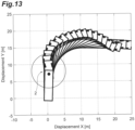
- FIG. 13 is a diagram illustrating parking route generation according to a comparative example.
- the forward route is determined first, and then the backward route is determined, and a vehicle posture of the coupled vehicle 2 is bent at a point in time when the coupled vehicle 2 has reached the target parking position.
- a problem occurs more noticeably in the coupled vehicle 2 having a coupling angle.
- the backward route is determined first and then the forward route is determined (the route determination is made in reverse order from the target parking position A2), there are no restrictions regarding the forward route when the backward route is determined, making it possible to generate an ideal parking route by curbing bending of the vehicle posture at the time of parking.
- the route determination unit 25 may determine the parking route on the basis of one backward trajectory profile having the lowest degree of change in curvature in the route among the plurality of backward trajectory profiles in which the coupled vehicle 2 does not collide with the obstacle 50. Accordingly, since a route in which the number of steering wheel operations is as small as possible is selected for the backward route, it is possible to curb driver's discomfort at the time of backward movement.
- the current position of the coupled vehicle 2 is measured by the GPS receiver 17 of the car navigation 11, but the position detection unit that detects the current position of the coupled vehicle 2 is not limited to the GPS receiver 17.
- the current position of the coupled vehicle 2 may be estimated by using a laser SLAM scheme in which data from a laser sensor that irradiates an area around the coupled vehicle 2 with a laser and receives reflected light of the laser has been used, or the current position of the coupled vehicle 2 may be estimated by using a visual SLAM scheme in which a captured image of a camera has been used.
- the obstacle 50 present around the coupled vehicle 2 is detected by using the camera 13, but the present invention is not limited to this form, and the obstacle 50 present around the coupled vehicle 2 may be detected by using a laser sensor, a radar sensor, or the like instead of the camera 13 or together with the camera 13.
- the target route of the trailer 4 is generated by using a tri-clothoid curve in the above embodiment, but the present invention is not limited to this form, and a curve on which the curvature between the initial position and the target position of the trailer 4 changes continuously may be used.
- a curve on which the curvature between the initial position and the target position of the trailer 4 changes continuously may be used. Examples of such a curve include a Biarc curve, a Clothoid curve, a Bezier curve, and a Spline curve.
- the coupled vehicle 2 is a semi-trailer type truck in the embodiment, the present invention is also applicable to a full trailer type truck. Further, the present invention is not particularly limited to trucks, but can also be applied to coupled vehicles such as buses.
- the parking route generation device 16 of the embodiment is included in a travel control device that moves the coupled vehicle 2 backward through automatic driving
- the present invention is not particularly limited to this form and can also be applied to a case in which backward parking of the coupled vehicle 2 is performed through manual driving by using a parking assistance system.
- the parking route generation device 16 of the embodiment is applied to a parking assistance system that assists in the backward parking of the coupled vehicle 2, but the present invention is not particularly limited to the backward parking of the coupled vehicle 2, and can also be applied to, for example, forward traveling, such as turning left or right at an intersection.
Landscapes
- Engineering & Computer Science (AREA)
- Physics & Mathematics (AREA)
- General Physics & Mathematics (AREA)
- Radar, Positioning & Navigation (AREA)
- Remote Sensing (AREA)
- Automation & Control Theory (AREA)
- Mechanical Engineering (AREA)
- Transportation (AREA)
- Combustion & Propulsion (AREA)
- Chemical & Material Sciences (AREA)
- Aviation & Aerospace Engineering (AREA)
- Human Computer Interaction (AREA)
- Control Of Driving Devices And Active Controlling Of Vehicle (AREA)
- Traffic Control Systems (AREA)
- Steering Control In Accordance With Driving Conditions (AREA)
Abstract
Description
- One aspect of the present invention relates to a parking route generation device.
- For example,
Patent Literature 1 describes a backward parking assistance device that assists with backward parking of a coupled vehicle including a tractor and a trailer. The backward parking assistance device described inPatent Literature 1 creates a parking target route from a host vehicle position to a target parking position, and sets a steering angle of the coupled vehicle so that the coupled vehicle moves along the parking target route. In this case, for the parking target route, a traveling trajectory of the coupled vehicle when follow-up control is performed using a Pure Pursuit method is created. - [Patent Literature 1]
Japanese Unexamined Patent Publication No. 2018-199458 - Here, in a parking route for the coupled vehicle, movement is particularly complex at the time of backward movement. Therefore, there is a problem in that it is difficult to generate a backward route with high precision when the parking route for the coupled vehicle is generated, and a calculation cost increases due to an attempt to generate the backward route with as high precision as possible.
- One aspect of the present invention has been made in view of these circumstances, and an object of the present invention is to generate a parking route for a coupled vehicle with high accuracy and at a low calculation cost.
- A parking route generation device according to an aspect of the present invention is a parking route generation device for generating a parking route for causing a coupled vehicle including a tractor and a trailer to park, the parking route generation device including: a pattern storage unit configured to store a plurality of backward route patterns with a rear axle of the trailer as a reference for each wheelbase type of the trailer, the plurality of backward route patterns being a plurality of backward route patterns having different degrees of change in curvature in the route; a position setting unit configured to set a parking start position of the coupled vehicle and a target parking position of the coupled vehicle on the basis of information including a current position of the coupled vehicle; a trajectory generation unit configured to specify the plurality of backward route patterns corresponding to a wheelbase type of the trailer in the coupled vehicle on the basis of information indicating the wheelbase type of the trailer in the coupled vehicle and information stored in the pattern storage unit, and generate a plurality of backward route profiles on the basis of the plurality of specified backward route patterns; a trajectory selection unit configured to select the backward trajectory profile in which the coupled vehicle does not collide with an obstacle on the basis of the target parking position, information on the obstacle near the coupled vehicle, and the plurality of backward trajectory profiles; a route determination unit configured to determine a parking route so that the coupled vehicle that has started parking from the parking start position is parked at the target parking position through backward movement after forward movement, on the basis of the parking start position, the target parking position, and the backward trajectory profile selected by the trajectory selection unit; and a route output unit configured to output the parking route determined by the route determination unit.
- In the parking route generation device according to the aspect of the present embodiment, the plurality of backward route patterns with a rear axle of the trailer as a reference are stored for each wheelbase type of the trailer in advance. When the parking route is generated, the plurality of backward trajectory profiles corresponding to the wheelbase type of the trailer in the coupled vehicle are specified, and the plurality of backward trajectory profiles are generated on the basis of the plurality of specified backward trajectory profiles. The backward trajectory profile in which the coupled vehicle does not collide with a nearby obstacle is selected from among the plurality of backward trajectory profiles generated in this way, and the parking route is determined on the basis of the selected backward trajectory profile, the parking start position, and the target parking position. In the parking route for the coupled vehicle, movement is particularly complex at the time of backward movement. Therefore, there is a problem in that it is difficult to generate the backward route with high precision in generation of the parking route for the coupled vehicle, and a calculation cost increases in order to generate the backward route with as high precision as possible. In this regard, in the parking route generation device according to the aspect of the present embodiment, since the plurality of backward route patterns are stored for each wheelbase type of the trailer in advance, and the backward route profile is selected from among such information stored in advance, it is possible to greatly reduce the calculation cost. Further, since the plurality of backward route patterns are stored for each wheelbase length of the trailer, it is possible to generate the backward route with high precision (with high reproducibility) depending on the type of trailer to be coupled to the tractor. As described above, with the parking route generation device according to the aspect of the present embodiment, it is possible to generate the parking route for the coupled vehicle with high accuracy and at a low calculation cost.
- The route determination unit may determine a backward movement start position at which the coupled vehicle starts the backward movement, on the basis of the target parking position and the backward trajectory profile selected by the trajectory selection unit, determine, as the backward route, a route to reach the target parking position along the selected backward trajectory profile from the backward movement start position, determine a forward route in which the coupled vehicle that has started forward movement from the parking start position reaches the backward movement start position without collision with the obstacle, on the basis of the parking start position, the backward movement start position, and the information on the obstacle, after determining the backward route, and determine the parking route on the basis of the forward route and the backward route. For example, when the forward route is determined first and then the backward route is determined in an order of actual traveling routes, there may be restrictions regarding the forward route in determining the backward route, and for example, a vehicle posture may be bent at a point in time when the target parking position is reached. Such a problem occurs more noticeably in the coupled vehicle having a coupling angle. In this respect, since the backward route is determined first and then the forward route is determined (the route determination is made in reverse order from the target parking position), there are no restrictions regarding the forward route when the backward route is determined, making it possible to generate an ideal parking route by curbing bending of the vehicle posture at the time of parking.
- When there are a plurality of backward trajectory profiles in which the coupled vehicle does not collide with the obstacle, the route determination unit may determine the parking route on the basis of one backward trajectory profile having a lowest degree of change in curvature in the route among the plurality of backward trajectory profiles in which the coupled vehicle does not collide with the obstacle. Accordingly, since a route in which the number of steering wheel operations is as small as possible is selected for the backward route, it is possible to curb a driver's discomfort at the time of backward movement.
- According to an aspect of the present invention, it is possible to generate the parking route for the coupled vehicle with high accuracy and at a low calculation cost.
-
-
FIG. 1 is a block diagram schematically illustrating a parking control device including a parking route generation device according to an embodiment of the present invention. -
FIG. 2 is a side view of a coupled vehicle having the parking control device illustrated inFIG. 1 mounted thereon. -
FIG. 3 is a plan view illustrating a state in which the coupled vehicle illustrated inFIG. 2 is parking. -
FIG. 4 is a diagram illustrating a backward route pattern. -
FIG. 5 is a diagram illustrating a backward route pattern for each trailer wheelbase length. -
FIG. 6 is a flowchart illustrating details of a procedure of a route generation process executed by a route generation ECU illustrated inFIG. 1 . -
FIG. 7 is a diagram illustrating a setting of a virtual parking space. -
FIG. 8 is a diagram illustrating generation of a tractor backward trajectory. -
FIG. 9 is a diagram illustrating movement of a backward trajectory profile. -
FIG. 10 is a diagram illustrating a collision determination using an obstacle map. -
FIG. 11 is a diagram illustrating a collision determination using an obstacle map. -
FIG. 12 is a diagram illustrating backward route selection based on a priority. -
FIG. 13 is a diagram illustrating parking route generation according to a comparative example. - Hereinafter, embodiments of the present invention will be described in detail with reference to the drawings. In the respective figures, the same or corresponding parts are denoted by the same reference signs, and redundant description will be omitted.
-
FIG. 1 is a block diagram schematically illustrating a parking control device including a parking route generation device according to an embodiment of the present invention. InFIG. 1 , theparking control device 1 according to the present embodiment is a device that automatically causes a coupledvehicle 2 to park in a parking lot or the like, as illustrated inFIGS. 2 and3 . - Here, the coupled
vehicle 2 is a large semi-trailer truck. The coupledvehicle 2 may be a medium-sized truck or a small-sized truck. The coupledvehicle 2 includes atractor 3 and atrailer 4 disposed on the rear side of thetractor 3. Thetrailer 4 is rotatably coupled to thetractor 3 at acoupling portion 5. - The
tractor 3 includes avehicle body 6, a pair of left and rightfront wheels 7 rotatably supported on the front side of thevehicle body 6, and a pair of left and rightrear wheels 8 rotatably supported on the rear side of thevehicle body 6. Thetractor 3 has an engine (not illustrated) mounted thereon. Thetrailer 4 includes avehicle body 9 and a pair of left andright wheels 10 rotatably supported on the rear side of thevehicle body 9. - Referring back to
FIG. 1 , theparking control device 1 is mounted on thetractor 3 of the coupledvehicle 2. Theparking control device 1 includes acar navigation 11, acoupling angle sensor 12, acamera 13, aroute generation ECU 14, and a parking control ECU 15. - The
car navigation 11, thecoupling angle sensor 12, thecamera 13, and the route generation ECU 14 constitute a parkingroute generation device 16 of the present embodiment. The parkingroute generation device 16 is a device that generates a parking route for causing theparking control device 1 to park the coupledvehicle 2. - As illustrated in
FIG. 3 , the parkingroute generation device 16 generates a parking route in which the coupledvehicle 2 moves forward from the side of a parking space H, turns around once, and then moves backward into the parking space H. Specifically, the parkingroute generation device 16 generates a parking route in which the coupledvehicle 2 moves forward from a parking start position A1 to a turnaround position A3 (backward movement start position) and then moves backward from the turnaround position A3 to the target parking position A2. The parking start position A1, the target parking position A2, and the turnaround position A3 will be described in detail below. - The
car navigation 11 includes aGPS receiver 17 that receives radio waves transmitted from GPS satellites and measures the current position of the coupledvehicle 2, amap storage unit 18 that stores map data, adisplay 19 that displays the current position of the coupledvehicle 2 together with the map, and aninput unit 20 that sets and inputs data such as a destination of the coupledvehicle 2. - The
GPS receiver 17 constitutes a position detection unit that detects the current position of the coupledvehicle 2. TheGPS receiver 17 detects position coordinates and an azimuth angle of two-dimensional coordinates (X and Y coordinates) of thetractor 3 as the current position of the coupledvehicle 2. - The
coupling angle sensor 12 is a sensor that detects a coupling angle between thetractor 3 and thetrailer 4. The coupling angle is an angle at which an imaginary line extending in a front-rear direction of thetractor 3 intersects with an imaginary line extending in a front-rear direction of thetrailer 4. The coupling angle is 0 degrees in a state in which thetractor 3 and thetrailer 4 are disposed on the same straight line. - The
camera 13 is an imaging unit that images surroundings of the coupledvehicle 2. Thecamera 13 is provided, for example, in each of thetractor 3 and thetrailer 4. Thecamera 13 constitutes an environment detection unit that detects a surrounding environment of the coupledvehicle 2, such as the presence or absence of an obstacle 50 (FIG. 3 ). - Examples of the
obstacle 50 may include another parked vehicle 51 (seeFIG. 3 or the like), awall 52 of a building (seeFIG. 7 or the like), and a curb. When thewall 52 of the building is known from map data stored in thecar navigation 11, themap storage unit 18 of thecar navigation 11 also constitutes the environment detection unit described above. - The
route generation ECU 14 includes a CPU, a RAM, a ROM, an input and output interface, and the like. Theroute generation ECU 14 receives information of thecar navigation 11, a detection value of thecoupling angle sensor 12, and a captured image of thecamera 13, executes processing regarding generation of a parking route for the coupledvehicle 2, and outputs data including the parking route for the coupledvehicle 2 to theparking control ECU 15. - The
route generation ECU 14 includes apattern storage unit 21, aposition setting unit 22, atrajectory generation unit 23, atrajectory selection unit 24, aroute determination unit 25, and aroute output unit 26. - The
pattern storage unit 21 stores the plurality of backward route patterns with a rear axle of thetrailer 4 as a reference for each wheelbase length (wheelbase type) of thetrailer 4. Thepattern storage unit 21 groups, for example, a plurality of types oftrailers 4 that can be coupled to thetractor 3 for a predetermined range of wheelbase lengths, and stores the plurality of backward route patterns for each group. Specifically, thepattern storage unit 21 divides thetrailers 4, for example, into a group oftrailers 4 having a wheelbase length of 6 m or less, a group oftrailers 4 having a wheelbase length of more than 6 m and 8 m or less, and a group oftrailers 4 having a wheelbase length of more than 8 m and 10 m or less, and stores the plurality of backward route patterns for each group. - Each of the plurality of backward route patterns is a trajectory that the rear axle of the
trailer 4 having the corresponding wheelbase length can actually take at the time of backward movement. The trajectory of the backward route pattern is represented by a curved line whose curvature changes continuously. The backward route pattern is a backward trajectory profile at a rear axle center of thetrailer 4 when the coupledvehicle 2 turns in a most space-saving manner. The plurality of backward route patterns belonging to the group having the same wheelbase length have different degrees of change in curvature in the route. The plurality of backward route patterns illustrated inFIG. 4 indicate the plurality of backward route patterns belonging to the group having the same wheelbase length, and seven backward route patterns having different degrees of change in curvature in the route are indicated as backward route patterns toward a common target parking position A2. In the example illustrated inFIG. 4 , the backward route pattern is illustrated in 15° increments in a range of 0° to 90° with the target parking position A2 as a reference. As illustrated inFIG. 4 , when a degree of change in curvature of the plurality of backward route patterns is lower, the backward route pattern is more likely to be selected in trajectory selection that will be described below, that is, the priority may be higher. - As illustrated in
FIG. 5 , in a group oftrailers 4 having a wheelbase length of 6 m or less (seeFIG. 5(a) ), a group oftrailers 4 having a wheelbase length of greater than 6 m and 8 m or less (seeFIG. 5(b) ), and a group oftrailers 4 having a wheelbase length of greater than 8 m and 10 m or less (seeFIG. 5(c) ), a plurality of different backward route patterns (trajectory profiles) are different. In the parkingroute generation device 16 according to the present embodiment, it is possible to generate the backward route with high precision (high reproducibility) since the backward route is generated on the basis of a backward route pattern close to an actual wheelbase length of thetrailer 4. - A tri-clothoid, for example, is used for design of the backward route pattern. However, since the backward route pattern is generated by off-line calculation, the backward route pattern may be generated by using a scheme with a higher load than the tri-clothoid.
- The
position setting unit 22 sets the parking start position A1 of the coupledvehicle 2 and the target parking position A2 of the coupledvehicle 2 on the basis of information including the current position of the coupledvehicle 2. Theposition setting unit 22 uses the current position of the coupledvehicle 2 detected by theGPS receiver 17 of thecar navigation 11 to set the parking start position A1 (seeFIG. 3 ) of the coupledvehicle 2. Specifically, theposition setting unit 22 sets the parking start position A1 of the coupledvehicle 2 on the basis of the current position of the coupledvehicle 2 and the coupling angle θ between thetractor 3 and thetrailer 4 detected by thecoupling angle sensor 12. Theposition setting unit 22 acquires, for example, position coordinates, an azimuth angle, and a turning curvature of thetrailer 4 as the parking start position A1 of the coupledvehicle 2. - The
position setting unit 22 sets the target parking position A2 (seeFIG. 3 ) of the coupledvehicle 2 using the information of thecar navigation 11 including the current position of the coupledvehicle 2 detected by theGPS receiver 17. Specifically, theposition setting unit 22 sets the target parking position A2 of the coupledvehicle 2 on the basis of information of thecar navigation 11 including the current position of the coupledvehicle 2, the coupling angle θ between thetractor 3 and thetrailer 4 detected by thecoupling angle sensor 12, and the captured image of thecamera 13. The target parking position A2 may be input as coordinate information from the outside of the present system according to an external instruction (an HMI operation by the driver, an instruction from a traffic control, or the like), autonomous parking space detection in an upper processing layer of an automatic driving system, or the like. Theposition setting unit 22 acquires, for example, the position coordinates, azimuth angle, and turning curvature of thetrailer 4 as the target parking position A2 of the coupledvehicle 2. Details of the processing of theposition setting unit 22 will be described below. - The
trajectory generation unit 23 generates the plurality of backward trajectory profiles. Thetrajectory generation unit 23 specifies the plurality of backward route patterns corresponding to the wheelbase length of thetrailer 4 in the coupledvehicle 2 on the basis of information indicating the wheelbase length of thetrailer 4 in the coupledvehicle 2, and information stored in the pattern storage unit 21 (the plurality of backward route patterns for each wheelbase length of the trailer 4). That is, thetrajectory generation unit 23 specifies the plurality of backward route patterns corresponding to the wheelbase length of thetrailer 4 that is a target for which backward trajectory profiles are to be generated. Information such as the wheelbase length of thetrailer 4 may be acquired, for example, by causing thetrailer 4 to include an ID tag and reading the ID tag, or may also be estimated by image processing by the wheels being imaged by a camera mounted on thetractor 3 side. For example, in the example illustrated inFIG. 5 , when the wheelbase length of thetrailer 4 is 7 m, the plurality of backward route patterns illustrated inFIG. 5(b) are specified (extracted). Thetrajectory generation unit 23 generates the plurality of backward trajectory profiles on the basis of the plurality of specified backward route patterns. Specifically, thetrajectory generation unit 23 generates the backward trajectory profile (tractor backward trajectories) indicating a backward trajectory of thetractor 3 from the plurality of backward trajectory profiles with the rear axle of thetrailer 4 as a reference. Details of processing of thetrajectory generation unit 23 will be described below. - The
trajectory selection unit 24 selects a backward trajectory profile in which the coupledvehicle 2 does not collide with an obstacle, on the basis of the target parking position A2, information on theobstacle 50 around the coupledvehicle 2, and the plurality of backward trajectory profiles (tractor backward trajectories) generated by thetrajectory generation unit 23. The information on theobstacle 50 around the coupledvehicle 2 is acquired from thecamera 13 that can function as the environment detection unit and themap storage unit 18 of thecar navigation 11. Thetrajectory selection unit 24 selects one or more backward trajectory profiles in which the trajectory does not overlap the obstacle 50 (that is, thevehicle body 9 of thetrailer 4 or thevehicle body 6 of thetractor 3 does not collide with the objects 50) from among the plurality of backward trajectory profiles (tractor backward trajectories) leading to the target parking position A2. Details of the processing of thetrajectory selection unit 24 will be described below. - The
route determination unit 25 determines the parking route so that the coupledvehicle 2 that has started parking from the parking start position A1 is parked at the target parking position A2 through backward movement after forward movement, on the basis of the target parking position A2 and the backward trajectory profile selected by thetrajectory selection unit 24. - The
route determination unit 25 first determines the turnaround position A3 (backward movement start position) at which the coupledvehicle 2 starts backward movement, on the basis of the target parking position A2 and the backward trajectory profile selected by thetrajectory selection unit 24. Theroute determination unit 25 determines, as the backward route, a route from the turnaround position A3 to the target parking position A2 along the selected backward trajectory profile. - After the
route determination unit 25 determines the above-described backward route, theroute determination unit 25 determines the forward route in which the coupledvehicle 2 that has started forward movement from the parking start position A1 reaches the turnaround position A3 without collision with theobstacle 50, on the basis of the parking start position A1, the turnaround position A3, and the information on theobstacle 50. Theroute determination unit 25 determines the parking route by collating the forward route with the backward route. - When there are the plurality of backward trajectory profiles selected by the
trajectory selection unit 24, theroute determination unit 25 determines the turnaround position A3 for each of the backward trajectory profiles, and determines the backward route and the forward route. When there are the plurality of backward trajectory profiles selected by thetrajectory selection unit 24, theroute determination unit 25 may determine the backward route of the parking route on the basis of one backward trajectory profile having a lowest degree of change in curvature in the route among the plurality of backward trajectory profiles. - The
route determination unit 25 uses a geometric model of the coupledvehicle 2 to perform a vehicle motion simulation in which the coupledvehicle 2 performs follow-up control through forward traveling from the parking start position A1 and the target parking position A2 to the turnaround position A3, to thereby calculate a data series of the steering angle of thetractor 3 and a data series of each posture angle of thetractor 3 and thetrailer 4. The data series is history data. - The
route output unit 26 outputs data of the parking route (parking route data) determined by theroute determination unit 25 to theparking control ECU 15. Further, theroute output unit 26 outputs the data series of the steering angle of thetractor 3 and the data series of each posture angle of thetractor 3 and thetrailer 4 to theparking control ECU 15. - The
parking control ECU 15 includes a CPU, a RAM, a ROM, an input and output interface, and the like. Theparking control ECU 15 receives the parking route data and data series from theroute generation ECU 14, the information from thecar navigation 11, and the detection value from thecoupling angle sensor 12, and executes processing regarding automatic parking of the coupledvehicle 2. - The
parking control ECU 15 includes astorage unit 31 and a follow-upcontrol unit 32. Thestorage unit 31 stores the parking route data and the data series output from theroute output unit 26 of theroute generation ECU 14. - The follow-up
control unit 32 performs steering control and speed control of the coupledvehicle 2 to park the coupledvehicle 2 at the target parking position A2 according to the parking route data and data series stored in thestorage unit 31. The follow-upcontrol unit 32 controls the steering of the coupledvehicle 2 in the steering control of the coupledvehicle 2, and controls an accelerator and a brake in the speed control of the coupledvehicle 2. - In this case, the follow-up
control unit 32 performs feedforward control of steering of thetractor 3 to park the coupledvehicle 2 at the target parking position A2, according to the data series of the steering angle of thetractor 3 and the data series of each of posture angles of thetractor 3 and thetrailer 4. That is, the follow-upcontrol unit 32 performs feedforward control of the steering of thetractor 3 with the data series of the steering angle of thetractor 3 and the data series of each posture angle of thetractor 3 and thetrailer 4 as target values. Further, the follow-upcontrol unit 32 performs feedback control of the steering of thetractor 3 so that the coupledvehicle 2 is parked at the target parking position A2, on the basis of the coupling angle θ between thetractor 3 and thetrailer 4 detected by thecoupling angle sensor 12 and the current position of the coupledvehicle 2 detected by theGPS receiver 17. - The follow-up
control unit 32 performs, for example, follow-up control for virtually considering a vehicle in a target posture on a target route of thetrailer 4 given by a tri-clothoid curve and making a relative error of an actual vehicle with respect to the target value close to 0 as a state quantity. An example of the follow-up control for making an error state quantity close to 0 may include LQ control. - Next, the procedure of a route generation process will be described in detail with reference to
FIG. 6. FIG. 6 is a flowchart illustrating details of the procedure of the route generation process executed by theroute generation ECU 14. This process is executed when a driver of the coupledvehicle 2 instructs to start parking assistance. In this case, the driver may set and input a target parking position candidate for the coupledvehicle 2 using theinput unit 20 of thecar navigation 11. - As illustrated in
FIG. 6 , theroute generation ECU 14 sets a virtual parking space at the target parking position A2 (step S1). As a premise of this process, theroute generation ECU 14 first acquires the position coordinates, azimuth angle, and turning curvature of thetrailer 4 as the parking start position A1 of the coupledvehicle 2 on the basis of the information of thecar navigation 11 including theGPS receiver 17 and the detection value of thecoupling angle sensor 12. The position coordinates of thetrailer 4 are, for example, position coordinates of the rear axle center of thetrailer 4. As illustrated inFIG. 3 , the rear axle center of thetrailer 4 is a center in an axial direction (a vehicle width direction of the trailer 4) of avehicle axle 10a coupled to the pair of left andright wheels 10 disposed on the rear side of thetrailer 4. The azimuth angle of thetrailer 4 corresponds to a yaw angle of thetrailer 4. The azimuth angle of thetractor 3 corresponds to a yaw angle of thetractor 3. Further, the turning curvature of thetrailer 4 uniquely corresponds to the coupling angle of thetrailer 4 with respect to thetractor 3 on condition that steady turning of the coupledvehicle 2 is assumed. Therefore, the coupling angle θ between thetractor 3 and thetrailer 4 is obtained by using an algebraic formula with the turning curvature of thetrailer 4 as an input. Therefore, the turning curvature of thetrailer 4 is obtained from the coupling angle θ between thetractor 3 and thetrailer 4. In a state in which the coupling angle θ between thetractor 3 and thetrailer 4 is 0 degrees, the turning curvature of thetrailer 4 is 0. Further, theroute generation ECU 14 sets the position coordinates, azimuth angle, and turning curvature of thetrailer 4 as the target parking position A2 of the coupledvehicle 2 on the basis of the information of thecar navigation 11 including theGPS receiver 17, the detection value of thecoupling angle sensor 12, and the captured image of thecamera 13. - As illustrated in
FIG. 7 , theroute generation ECU 14 sets virtual walls V1 to V3 constituting a virtual parking space that surrounds three sides of the target parking position A2. In the example illustrated inFIG. 7 , the virtual walls V1 and V2 are virtual walls that surround side surfaces of the coupledvehicle 2, and the virtual wall V3 is a virtual wall that surrounds a rear part of the coupledvehicle 2. Theroute generation ECU 14 sets a backward route to be described below so that the coupledvehicle 2 does not come into contact the virtual walls V1 to V3. - Subsequently, the
route generation ECU 14 generates the plurality of backward trajectory profiles (tractor backward trajectories) indicating the backward trajectories of the tractor 3 (step S2). Theroute generation ECU 14 first specifies the plurality of backward route patterns corresponding to the wheelbase length of thetrailer 4 in the coupledvehicle 2 on the basis of the information indicating the wheelbase length of thetrailer 4 in the coupledvehicle 2 and the information stored in the pattern storage unit 21 (the plurality of backward route patterns for each wheelbase length of the trailer 4). That is, theroute generation ECU 14 specifies the plurality of backward route patterns corresponding to the wheelbase length of thetrailer 4 that is a target for which backward trajectory profiles are to be generated (see an upper diagram inFIG. 8 ). Such a backward route pattern is generated by using a tri-clothoid curve as a curve on which a curvature changes continuously from an initial position to a target position. - The tri-clothoid curve is a curve in which sudden change in curvature do not occur. The tri-clothoid curve is a smooth curve whose initial and end curves and positions can be arbitrarily designated through a combination of three clothoid curves with the same route lengths. The tri-clothoid curve can be simply obtained by numerically solving a 2-variable nonlinear equation. The tri-clothoid curve is described in detail in "Route generation scheme capable of designating initial and end curvatures using a clothoid curve" in the Transactions of the Japan Society of Mechanical Engineers (Vol. 85, No. 878, 2019).
- The
route generation ECU 14 generates the plurality of backward trajectory profiles on the basis of the plurality of specified backward route patterns. Specifically, theroute generation ECU 14 generates the backward trajectory profile (tractor backward trajectories) indicating the backward trajectories of thetractor 3 from the plurality of backward trajectory profiles with the rear axle of thetrailer 4 as a reference. In an upper diagram in a lower part ofFIG. 8 , a trajectory of the rear axle of thetrailer 4 is indicated by a solid line, and a trajectory of a rear axle of thetractor 3 is indicated by a broken line. Theroute generation ECU 14 derives the trajectory of the rear axle of thetractor 3 indicated by the broken line, on the basis of, for example, the trajectory of the rear axle of thetrailer 4 indicated by the solid line and dimensions of thevehicle body 9 of thetrailer 4. Theroute generation ECU 14 derives the trajectory of the entire coupledvehicle 2 on the basis of the trajectory of the rear axle of thetrailer 4 and the trajectory of the rear axle of thetractor 3, as illustrated in a lower diagram in a lower part ofFIG. 8 . Theroute generation ECU 14 generates the backward trajectory profile for each of the plurality of backward route patterns, as illustrated in a lower part ofFIG. 8 . - Subsequently, the
route generation ECU 14 moves (adjusts) a position of each backward trajectory profile so that the backward trajectory profile fits within the virtual walls V1 to V3 constituting the virtual parking space (step S3). As illustrated inFIGS. 9(a) and 9(b) , the backward trajectory profile is moved in a Y-axis (vertical) direction so that a position at which the coupledvehicle 2 does not collide with the virtual parking space is found.FIG. 9(a) is a diagram in which the backward trajectory profile has been greatly moved in a negative direction of a Y-axis, andFIG. 9(b) is a diagram in which the backward trajectory profile has been greatly moved in a positive direction of the Y-axis. Theroute generation ECU 14 uses, for example, a binary search method to set the backward trajectory profile at a position at which the coupledvehicle 2 does not collide with the virtual parking space and which is as close to the target parking position A2 as possible. As illustrated inFIG. 9(c) , once the position of the backward trajectory profile is determined, theroute generation ECU 14 modifies the trajectory to add a straight section to a goal (the target parking position A2). - Subsequently, the
route generation ECU 14 performs a collision determination related to the backward route of the coupledvehicle 2 on the basis of the obstacle map (step S4). The obstacle map is information indicating the position of theobstacle 50 acquired from thecamera 13 which can function as the environment detection unit and themap storage unit 18 of thecar navigation 11. Theroute generation ECU 14 determines whether the vehicle collides with an obstacle 50 (whether theobstacle 50 exists on the trajectory) for the plurality of backward trajectory profiles (tractor backward trajectories) leading to the target parking position A2. In an example illustrated inFIG. 10 , backward trajectory profiles C1 to C3 among seven backward trajectory profiles C1 to C7 collide with thewall 52 of the building, which is theobstacle 50. In this case, theroute generation ECU 14 leaves (selects) the backward trajectory profiles C4 to C7 other than the backward trajectory profiles C1 to C3 as candidate routes for the backward route. - Subsequently, the
route generation ECU 14 determines the turnaround position A3 (backward movement start position) at which the coupledvehicle 2 starts backward movement, on the basis of the target parking position A2 and the backward trajectory profile selected by thetrajectory selection unit 24. Theroute generation ECU 14 generates a forward route of a tractor trajectory on the basis of the parking start position A1 and the turnaround position A3 (step S5). - Subsequently, the
route generation ECU 14 performs a collision determination related to the forward route of the coupledvehicle 2 on the basis of the obstacle map (step S6). The obstacle map is information indicating the position of theobstacle 50 acquired from thecamera 13 which can function as the environment detection unit and themap storage unit 18 of thecar navigation 11. Theroute generation ECU 14 determines whether a plurality of forward trajectory profiles (tractor forward trajectories) from the parking start position A1 to the turnaround position A3 collide with the obstacle 50 (whether theobstacle 50 is present on the trajectory). In the example illustrated inFIG. 11 , the forward trajectory profile does not collide with, for example, thewall 52 of the building, which is theobstacle 50. Thus, theroute generation ECU 14 specifies candidate routes for the forward route. - When there are a plurality of candidate routes, the
route generation ECU 14 determines one final route from the candidate routes on the basis of a preset priority. In the example illustrated inFIG. 12 , the backward trajectory profiles C4 to C7 are selected as candidate routes for the backward route. In this case, theroute generation ECU 14 determines, for example, the backward trajectory profile C4 having the lowest degree of change in curvature in the route among the plurality of backward trajectory profiles C4 to C7, as a final route of the backward route. The forward route is also determined to be a forward route that is continuous with the backward trajectory profile C4. - Finally, the
route generation ECU 14 uses the geometric model of the coupledvehicle 2 to perform a vehicle motion simulation in which the coupledvehicle 2 performs follow-up control through forward traveling from the parking start position A1 and the target parking position A2 to the turnaround position A3, to thereby calculate a data series of the steering angle of thetractor 3 and a data series of each posture angle of thetractor 3 and thetrailer 4. The data series is history data. - Next, effects of the parking
route generation device 16 according to the present embodiment will be described. - The parking route generation device 16 according to the present embodiment is a parking route generation device that generates a parking route for causing the coupled vehicle 2 including the tractor 3 and the trailer 4 to park, and includes the pattern storage unit 21 that stores the plurality of backward route patterns with the rear axle of the trailer 4 as a reference for each wheelbase length of the trailer 4, the plurality of backward route patterns being a plurality of backward route patterns having a different degree of change in curvature in the route; the position setting unit 22 that sets the parking start position A1 of the coupled vehicle 2 and the target parking position A2 of the coupled vehicle 2 on the basis of the information including the current position of the coupled vehicle 2; the trajectory generation unit 23 that specifies the plurality of backward route patterns corresponding to the wheelbase length of the trailer 4 in the coupled vehicle 2 on the basis of the information indicating the wheelbase length of the trailer 4 in the coupled vehicle 2 and the information stored in the pattern storage unit 21, and generates a plurality of backward route profiles on the basis of the plurality of specified backward route patterns; the trajectory selection unit 24 that selects the backward trajectory profile in which the coupled vehicle 2 does not collide with the obstacle 50 on the basis of the target parking position A2, the information on the obstacle 50 around the coupled vehicle 2, and the plurality of backward trajectory profiles; the route determination unit 25 that determines the parking route so that the coupled vehicle 2 that has started parking from the parking start position A1 is parked at the target parking position A2 through backward movement after forward movement, on the basis of the parking start position A1, the target parking position A2, and the backward trajectory profile selected by the trajectory selection unit 24; and the route output unit 26 that outputs the parking route determined by the route determination unit 25.
- In the parking
route generation device 16 according to the present embodiment, the plurality of backward route patterns with the rear axle of thetrailer 4 as a reference are stored for each wheelbase length of thetrailer 4 in advance. When the parking route is generated, the plurality of backward trajectory profiles corresponding to the wheelbase length of thetrailer 4 in the coupledvehicle 2 are specified, and the plurality of backward trajectory profiles are generated on the basis of the plurality of specified backward trajectory profiles. The backward trajectory profile in which the coupledvehicle 2 does not collide with the surroundingobstacle 50 is selected from among the plurality of backward trajectory profiles generated in this way, and the parking route is determined on the basis of the selected backward trajectory profile, the parking start position A1, and the target parking position A2. In the parking route for the coupledvehicle 2, a movement is complex particularly at the time of backward movement. Therefore, there is a problem in that it is difficult to generate the backward route with high precision in generation of the parking route for the coupledvehicle 2, and a calculation cost increases in order to generate the backward route with as high precision as possible. In this regard, in the parkingroute generation device 16 according to the present embodiment, since the plurality of backward route patterns are stored for each wheelbase length of thetrailer 4 in advance, and the backward route profile is selected from among such information stored in advance, it is possible to greatly reduce the calculation cost. Further, since the plurality of backward route patterns are stored for each wheelbase length of thetrailer 4, it is possible to generate the backward route with high precision (with high reproducibility) depending on the type oftrailer 4 to be coupled to the tractor. As described above, with the parkingroute generation device 16 according to the present embodiment, it is possible to generate the parking route for the coupledvehicle 2 with high accuracy and at low calculation cost. - The
route determination unit 25 may determine the turnaround position A3, which is a backward movement start position at which the coupledvehicle 2 starts the backward movement, on the basis of the target parking position A2 and the backward trajectory profile selected by thetrajectory selection unit 24, determine, as the backward route, a route to reach the target parking position A2 along the selected backward trajectory profile from the turnaround position A3, determine a forward route in which the coupledvehicle 2 that has started forward movement from the parking start position A1 reaches the turnaround position A3 without collision with theobstacle 50, on the basis of the parking start position A1, the turnaround position A3, and the information on theobstacle 50, after determining the backward route, and determine the parking route on the basis of the forward route and the backward route. For example, when the forward route is determined first and then the backward route is determined in an order of actual traveling routes, there may be restrictions regarding the forward route in determining the backward route and, for example, the vehicle posture may be bent at a point in time when the target parking position is reached.FIG. 13 is a diagram illustrating parking route generation according to a comparative example. In the example illustrated inFIG. 13 , the forward route is determined first, and then the backward route is determined, and a vehicle posture of the coupledvehicle 2 is bent at a point in time when the coupledvehicle 2 has reached the target parking position. Such a problem occurs more noticeably in the coupledvehicle 2 having a coupling angle. In this respect, since the backward route is determined first and then the forward route is determined (the route determination is made in reverse order from the target parking position A2), there are no restrictions regarding the forward route when the backward route is determined, making it possible to generate an ideal parking route by curbing bending of the vehicle posture at the time of parking. - When there are a plurality of backward trajectory profiles in which the coupled
vehicle 2 does not collide with theobstacle 50, theroute determination unit 25 may determine the parking route on the basis of one backward trajectory profile having the lowest degree of change in curvature in the route among the plurality of backward trajectory profiles in which the coupledvehicle 2 does not collide with theobstacle 50. Accordingly, since a route in which the number of steering wheel operations is as small as possible is selected for the backward route, it is possible to curb driver's discomfort at the time of backward movement. - The embodiments of the present invention have been described above, but the present invention is not limited to the above embodiments. For example, in the above embodiment, the current position of the coupled
vehicle 2 is measured by theGPS receiver 17 of thecar navigation 11, but the position detection unit that detects the current position of the coupledvehicle 2 is not limited to theGPS receiver 17. For example, the current position of the coupledvehicle 2 may be estimated by using a laser SLAM scheme in which data from a laser sensor that irradiates an area around the coupledvehicle 2 with a laser and receives reflected light of the laser has been used, or the current position of the coupledvehicle 2 may be estimated by using a visual SLAM scheme in which a captured image of a camera has been used. - Further, in the above embodiment, the
obstacle 50 present around the coupledvehicle 2 is detected by using thecamera 13, but the present invention is not limited to this form, and theobstacle 50 present around the coupledvehicle 2 may be detected by using a laser sensor, a radar sensor, or the like instead of thecamera 13 or together with thecamera 13. - Further, the target route of the
trailer 4 is generated by using a tri-clothoid curve in the above embodiment, but the present invention is not limited to this form, and a curve on which the curvature between the initial position and the target position of thetrailer 4 changes continuously may be used. Examples of such a curve include a Biarc curve, a Clothoid curve, a Bezier curve, and a Spline curve. - Further, although the coupled
vehicle 2 is a semi-trailer type truck in the embodiment, the present invention is also applicable to a full trailer type truck. Further, the present invention is not particularly limited to trucks, but can also be applied to coupled vehicles such as buses. - Further, the parking
route generation device 16 of the embodiment is included in a travel control device that moves the coupledvehicle 2 backward through automatic driving, the present invention is not particularly limited to this form and can also be applied to a case in which backward parking of the coupledvehicle 2 is performed through manual driving by using a parking assistance system. - Further, the parking
route generation device 16 of the embodiment is applied to a parking assistance system that assists in the backward parking of the coupledvehicle 2, but the present invention is not particularly limited to the backward parking of the coupledvehicle 2, and can also be applied to, for example, forward traveling, such as turning left or right at an intersection. -
- 2 Coupled vehicle
- 3 Tractor
- 4 Trailer
- 16 Parking route generation device
- 21 Pattern storage unit
- 22 Position setting unit
- 23 Trajectory generation unit
- 24 Trajectory selection unit
- 25 Route determination unit
- 26 Route output unit
- 50 Obstacle
- A1 Parking start position
- A2 Parking target position
- A3 Turnaround position (backward movement start position)
Claims (3)
- A parking route generation device for generating a parking route for causing a coupled vehicle including a tractor and a trailer to park, the parking route generation device comprising:a pattern storage unit configured to store a plurality of backward route patterns with a rear axle of the trailer as a reference for each wheelbase type of the trailer, the plurality of backward route patterns being a plurality of backward route patterns having different degrees of change in curvature in the route;a position setting unit configured to set a parking start position of the coupled vehicle and a target parking position of the coupled vehicle on the basis of information including a current position of the coupled vehicle;a trajectory generation unit configured to specify the plurality of backward route patterns corresponding to a wheelbase type of the trailer in the coupled vehicle on the basis of information indicating the wheelbase type of the trailer in the coupled vehicle and information stored in the pattern storage unit, and generate a plurality of backward route profiles on the basis of the plurality of specified backward route patterns;a trajectory selection unit configured to select the backward trajectory profile in which the coupled vehicle does not collide with an obstacle on the basis of the target parking position, information on the obstacle near the coupled vehicle, and the plurality of backward trajectory profiles;a route determination unit configured to determine a parking route so that the coupled vehicle that has started parking from the parking start position is parked at the target parking position through backward movement after forward movement, on the basis of the parking start position, the target parking position, and the backward trajectory profile selected by the trajectory selection unit; anda route output unit configured to output the parking route determined by the route determination unit.
- The parking route generation device according to claim 1, whereinthe route determination unitdetermines a backward movement start position at which the coupled vehicle starts the backward movement, on the basis of the target parking position and the backward trajectory profile selected by the trajectory selection unit, determines, as the backward route, a route to reach the target parking position along the selected backward trajectory profile from the backward movement start position,determines a forward route in which the coupled vehicle that has started forward movement from the parking start position reaches the backward movement start position without collision with the obstacle, on the basis of the parking start position, the backward movement start position, and the information on the obstacle, after determining the backward route, anddetermines the parking route on the basis of the forward route and the backward route.
- The parking route generation device according to claim 1 or 2, wherein, when there are a plurality of backward trajectory profiles in which the coupled vehicle does not collide with the obstacle, the route determination unit determines the parking route on the basis of one backward trajectory profile having a lowest degree of change in curvature in the route among the plurality of backward trajectory profiles in which the coupled vehicle does not collide with the obstacle.
Applications Claiming Priority (2)
| Application Number | Priority Date | Filing Date | Title |
|---|---|---|---|
| JP2021152125A JP7693480B2 (en) | 2021-09-17 | 2021-09-17 | Parking path generation device |
| PCT/JP2022/033614 WO2023042731A1 (en) | 2021-09-17 | 2022-09-07 | Parking route generation device |
Publications (2)
| Publication Number | Publication Date |
|---|---|
| EP4389541A1 true EP4389541A1 (en) | 2024-06-26 |
| EP4389541A4 EP4389541A4 (en) | 2025-08-27 |
Family
ID=85602195
Family Applications (1)
| Application Number | Title | Priority Date | Filing Date |
|---|---|---|---|
| EP22869878.3A Pending EP4389541A4 (en) | 2021-09-17 | 2022-09-07 | Parking route generation device |
Country Status (4)
| Country | Link |
|---|---|
| US (1) | US12579893B2 (en) |
| EP (1) | EP4389541A4 (en) |
| JP (1) | JP7693480B2 (en) |
| WO (1) | WO2023042731A1 (en) |
Families Citing this family (3)
| Publication number | Priority date | Publication date | Assignee | Title |
|---|---|---|---|---|
| JPWO2024224885A1 (en) * | 2023-04-27 | 2024-10-31 | ||
| CN116714606A (en) * | 2023-07-17 | 2023-09-08 | 上海友道智途科技有限公司 | An automatic parking control method for semi-trailer vehicles that combines feedforward and feedback |
| JP2025087010A (en) * | 2023-11-29 | 2025-06-10 | 三菱電機株式会社 | Trailer driving route output device |
Family Cites Families (6)
| Publication number | Priority date | Publication date | Assignee | Title |
|---|---|---|---|---|
| GB2515800B (en) | 2013-07-04 | 2017-06-07 | Jaguar Land Rover Ltd | Vehicle control system |
| EP4137385B1 (en) * | 2015-09-02 | 2025-10-29 | Volvo Truck Corporation | A device and a method for reversing an articulated vehicle combination |
| JP6764171B2 (en) | 2017-05-29 | 2020-09-30 | 日野自動車株式会社 | Backward parking support device for connected vehicles |
| WO2020157530A1 (en) | 2019-02-01 | 2020-08-06 | Carit Automotive GmbH & Co. KG | Vehicle park assist systems |
| US11987287B2 (en) * | 2019-04-12 | 2024-05-21 | Continental Autonomous Mobility US, LLC | Autonomous truck-trailer maneuvering and parking |
| US11112786B2 (en) * | 2019-06-11 | 2021-09-07 | Ford Global Technologies, Llc | Remote trailer maneuver-assist |
-
2021
- 2021-09-17 JP JP2021152125A patent/JP7693480B2/en active Active
-
2022
- 2022-09-07 EP EP22869878.3A patent/EP4389541A4/en active Pending
- 2022-09-07 WO PCT/JP2022/033614 patent/WO2023042731A1/en not_active Ceased
- 2022-09-07 US US18/690,766 patent/US12579893B2/en active Active
Also Published As
| Publication number | Publication date |
|---|---|
| WO2023042731A1 (en) | 2023-03-23 |
| US20240404411A1 (en) | 2024-12-05 |
| EP4389541A4 (en) | 2025-08-27 |
| JP2023044216A (en) | 2023-03-30 |
| JP7693480B2 (en) | 2025-06-17 |
| US12579893B2 (en) | 2026-03-17 |
Similar Documents
| Publication | Publication Date | Title |
|---|---|---|
| US12579893B2 (en) | Parking route generation device | |
| CN111066071B (en) | Position error correction method and position error correction device for driving assistance vehicle | |
| CN106080598B (en) | Real-time expected speed control | |
| EP3016835B1 (en) | Vehicle control system | |
| JP6082415B2 (en) | Vehicle travel control device | |
| EP3016836B1 (en) | Vehicle control system | |
| EP3791239A1 (en) | A method for establishing a path for a vehicle | |
| US20120277955A1 (en) | Driving assistance device | |
| EP3611077B1 (en) | Vehicle control method and vehicle control device | |
| JP6831734B2 (en) | Vehicle travel control device | |
| CN107054361A (en) | The steering control device of vehicle | |
| CN111572536A (en) | Multi-segment vertical parking path planning method and device | |
| CN113276840B (en) | Steering wheel reverse control method, automatic parking system and vehicle | |
| JP6764171B2 (en) | Backward parking support device for connected vehicles | |
| JP6803285B2 (en) | Vehicle travel control device | |
| JP7628242B2 (en) | Parking path generation device and parking control device | |
| US12503101B2 (en) | Motion planning with variable grid resolution for graph-search-based planning | |
| CN117584946A (en) | Obstacle avoidance for vehicles | |
| CN117999174A (en) | Method for assisting during a coupling process with a trailer, computing device and assistance system for a vehicle | |
| JP2022065364A (en) | Travel route generating device and travel control device | |
| CN118270104B (en) | Vehicle, vehicle control method, system, and storage medium | |
| CN117601854A (en) | Control method and device for adaptive cruise, vehicle and storage medium | |
| CN117980164A (en) | Method, computing device and assistance system for a vehicle for assisting during a coupling process with a trailer | |
| EP4001058A1 (en) | A system for guiding a vehicle towards a connecting vehicle which is to be connected to the vehicle | |
| US20220351620A1 (en) | Method for generating a routing map of an area to be used for guiding a vehicle in the area |
Legal Events
| Date | Code | Title | Description |
|---|---|---|---|
| STAA | Information on the status of an ep patent application or granted ep patent |
Free format text: STATUS: THE INTERNATIONAL PUBLICATION HAS BEEN MADE |
|
| PUAI | Public reference made under article 153(3) epc to a published international application that has entered the european phase |
Free format text: ORIGINAL CODE: 0009012 |
|
| STAA | Information on the status of an ep patent application or granted ep patent |
Free format text: STATUS: REQUEST FOR EXAMINATION WAS MADE |
|
| 17P | Request for examination filed |
Effective date: 20240318 |
|
| AK | Designated contracting states |
Kind code of ref document: A1 Designated state(s): AL AT BE BG CH CY CZ DE DK EE ES FI FR GB GR HR HU IE IS IT LI LT LU LV MC MK MT NL NO PL PT RO RS SE SI SK SM TR |
|
| DAV | Request for validation of the european patent (deleted) | ||
| DAX | Request for extension of the european patent (deleted) | ||
| A4 | Supplementary search report drawn up and despatched |
Effective date: 20250725 |
|
| RIC1 | Information provided on ipc code assigned before grant |
Ipc: B60R 99/00 20090101AFI20250721BHEP Ipc: G08G 1/16 20060101ALI20250721BHEP Ipc: B62D 15/02 20060101ALI20250721BHEP |