EP4389498A1 - Battery electric vehicle - Google Patents
Battery electric vehicle Download PDFInfo
- Publication number
- EP4389498A1 EP4389498A1 EP23214648.0A EP23214648A EP4389498A1 EP 4389498 A1 EP4389498 A1 EP 4389498A1 EP 23214648 A EP23214648 A EP 23214648A EP 4389498 A1 EP4389498 A1 EP 4389498A1
- Authority
- EP
- European Patent Office
- Prior art keywords
- characteristic data
- vehicle
- vehicle characteristic
- data
- special
- Prior art date
- Legal status (The legal status is an assumption and is not a legal conclusion. Google has not performed a legal analysis and makes no representation as to the accuracy of the status listed.)
- Pending
Links
Images




Classifications
-
- B—PERFORMING OPERATIONS; TRANSPORTING
- B60—VEHICLES IN GENERAL
- B60L—PROPULSION OF ELECTRICALLY-PROPELLED VEHICLES; SUPPLYING ELECTRIC POWER FOR AUXILIARY EQUIPMENT OF ELECTRICALLY-PROPELLED VEHICLES; ELECTRODYNAMIC BRAKE SYSTEMS FOR VEHICLES IN GENERAL; MAGNETIC SUSPENSION OR LEVITATION FOR VEHICLES; MONITORING OPERATING VARIABLES OF ELECTRICALLY-PROPELLED VEHICLES; ELECTRIC SAFETY DEVICES FOR ELECTRICALLY-PROPELLED VEHICLES
- B60L15/00—Methods, circuits, or devices for controlling the traction-motor speed of electrically-propelled vehicles
- B60L15/10—Methods, circuits, or devices for controlling the traction-motor speed of electrically-propelled vehicles for automatic control superimposed on human control to limit the acceleration of the vehicle, e.g. to prevent excessive motor current
-
- B—PERFORMING OPERATIONS; TRANSPORTING
- B60—VEHICLES IN GENERAL
- B60L—PROPULSION OF ELECTRICALLY-PROPELLED VEHICLES; SUPPLYING ELECTRIC POWER FOR AUXILIARY EQUIPMENT OF ELECTRICALLY-PROPELLED VEHICLES; ELECTRODYNAMIC BRAKE SYSTEMS FOR VEHICLES IN GENERAL; MAGNETIC SUSPENSION OR LEVITATION FOR VEHICLES; MONITORING OPERATING VARIABLES OF ELECTRICALLY-PROPELLED VEHICLES; ELECTRIC SAFETY DEVICES FOR ELECTRICALLY-PROPELLED VEHICLES
- B60L15/00—Methods, circuits, or devices for controlling the traction-motor speed of electrically-propelled vehicles
- B60L15/20—Methods, circuits, or devices for controlling the traction-motor speed of electrically-propelled vehicles for control of the vehicle or its driving motor to achieve a desired performance, e.g. speed, torque, programmed variation of speed
-
- B—PERFORMING OPERATIONS; TRANSPORTING
- B60—VEHICLES IN GENERAL
- B60W—CONJOINT CONTROL OF VEHICLE SUB-UNITS OF DIFFERENT TYPE OR DIFFERENT FUNCTION; CONTROL SYSTEMS SPECIALLY ADAPTED FOR HYBRID VEHICLES; ROAD VEHICLE DRIVE CONTROL SYSTEMS FOR PURPOSES NOT RELATED TO THE CONTROL OF A PARTICULAR SUB-UNIT
- B60W10/00—Conjoint control of vehicle sub-units of different type or different function
- B60W10/04—Conjoint control of vehicle sub-units of different type or different function including control of propulsion units
- B60W10/08—Conjoint control of vehicle sub-units of different type or different function including control of propulsion units including control of electric propulsion units, e.g. motors or generators
-
- B—PERFORMING OPERATIONS; TRANSPORTING
- B60—VEHICLES IN GENERAL
- B60W—CONJOINT CONTROL OF VEHICLE SUB-UNITS OF DIFFERENT TYPE OR DIFFERENT FUNCTION; CONTROL SYSTEMS SPECIALLY ADAPTED FOR HYBRID VEHICLES; ROAD VEHICLE DRIVE CONTROL SYSTEMS FOR PURPOSES NOT RELATED TO THE CONTROL OF A PARTICULAR SUB-UNIT
- B60W40/00—Estimation or calculation of non-directly measurable driving parameters for road vehicle drive control systems not related to the control of a particular sub unit, e.g. by using mathematical models
-
- B—PERFORMING OPERATIONS; TRANSPORTING
- B60—VEHICLES IN GENERAL
- B60W—CONJOINT CONTROL OF VEHICLE SUB-UNITS OF DIFFERENT TYPE OR DIFFERENT FUNCTION; CONTROL SYSTEMS SPECIALLY ADAPTED FOR HYBRID VEHICLES; ROAD VEHICLE DRIVE CONTROL SYSTEMS FOR PURPOSES NOT RELATED TO THE CONTROL OF A PARTICULAR SUB-UNIT
- B60W50/00—Details of control systems for road vehicle drive control not related to the control of a particular sub-unit, e.g. process diagnostic or vehicle driver interfaces
-
- B—PERFORMING OPERATIONS; TRANSPORTING
- B60—VEHICLES IN GENERAL
- B60L—PROPULSION OF ELECTRICALLY-PROPELLED VEHICLES; SUPPLYING ELECTRIC POWER FOR AUXILIARY EQUIPMENT OF ELECTRICALLY-PROPELLED VEHICLES; ELECTRODYNAMIC BRAKE SYSTEMS FOR VEHICLES IN GENERAL; MAGNETIC SUSPENSION OR LEVITATION FOR VEHICLES; MONITORING OPERATING VARIABLES OF ELECTRICALLY-PROPELLED VEHICLES; ELECTRIC SAFETY DEVICES FOR ELECTRICALLY-PROPELLED VEHICLES
- B60L2240/00—Control parameters of input or output; Target parameters
- B60L2240/10—Vehicle control parameters
- B60L2240/14—Acceleration
- B60L2240/16—Acceleration longitudinal
-
- B—PERFORMING OPERATIONS; TRANSPORTING
- B60—VEHICLES IN GENERAL
- B60L—PROPULSION OF ELECTRICALLY-PROPELLED VEHICLES; SUPPLYING ELECTRIC POWER FOR AUXILIARY EQUIPMENT OF ELECTRICALLY-PROPELLED VEHICLES; ELECTRODYNAMIC BRAKE SYSTEMS FOR VEHICLES IN GENERAL; MAGNETIC SUSPENSION OR LEVITATION FOR VEHICLES; MONITORING OPERATING VARIABLES OF ELECTRICALLY-PROPELLED VEHICLES; ELECTRIC SAFETY DEVICES FOR ELECTRICALLY-PROPELLED VEHICLES
- B60L2240/00—Control parameters of input or output; Target parameters
- B60L2240/40—Drive Train control parameters
- B60L2240/42—Drive Train control parameters related to electric machines
- B60L2240/421—Speed
-
- B—PERFORMING OPERATIONS; TRANSPORTING
- B60—VEHICLES IN GENERAL
- B60L—PROPULSION OF ELECTRICALLY-PROPELLED VEHICLES; SUPPLYING ELECTRIC POWER FOR AUXILIARY EQUIPMENT OF ELECTRICALLY-PROPELLED VEHICLES; ELECTRODYNAMIC BRAKE SYSTEMS FOR VEHICLES IN GENERAL; MAGNETIC SUSPENSION OR LEVITATION FOR VEHICLES; MONITORING OPERATING VARIABLES OF ELECTRICALLY-PROPELLED VEHICLES; ELECTRIC SAFETY DEVICES FOR ELECTRICALLY-PROPELLED VEHICLES
- B60L2240/00—Control parameters of input or output; Target parameters
- B60L2240/40—Drive Train control parameters
- B60L2240/42—Drive Train control parameters related to electric machines
- B60L2240/423—Torque
-
- B—PERFORMING OPERATIONS; TRANSPORTING
- B60—VEHICLES IN GENERAL
- B60L—PROPULSION OF ELECTRICALLY-PROPELLED VEHICLES; SUPPLYING ELECTRIC POWER FOR AUXILIARY EQUIPMENT OF ELECTRICALLY-PROPELLED VEHICLES; ELECTRODYNAMIC BRAKE SYSTEMS FOR VEHICLES IN GENERAL; MAGNETIC SUSPENSION OR LEVITATION FOR VEHICLES; MONITORING OPERATING VARIABLES OF ELECTRICALLY-PROPELLED VEHICLES; ELECTRIC SAFETY DEVICES FOR ELECTRICALLY-PROPELLED VEHICLES
- B60L2240/00—Control parameters of input or output; Target parameters
- B60L2240/70—Interactions with external data bases, e.g. traffic centres
-
- B—PERFORMING OPERATIONS; TRANSPORTING
- B60—VEHICLES IN GENERAL
- B60L—PROPULSION OF ELECTRICALLY-PROPELLED VEHICLES; SUPPLYING ELECTRIC POWER FOR AUXILIARY EQUIPMENT OF ELECTRICALLY-PROPELLED VEHICLES; ELECTRODYNAMIC BRAKE SYSTEMS FOR VEHICLES IN GENERAL; MAGNETIC SUSPENSION OR LEVITATION FOR VEHICLES; MONITORING OPERATING VARIABLES OF ELECTRICALLY-PROPELLED VEHICLES; ELECTRIC SAFETY DEVICES FOR ELECTRICALLY-PROPELLED VEHICLES
- B60L2250/00—Driver interactions
- B60L2250/18—Driver interactions by enquiring driving style
-
- B—PERFORMING OPERATIONS; TRANSPORTING
- B60—VEHICLES IN GENERAL
- B60L—PROPULSION OF ELECTRICALLY-PROPELLED VEHICLES; SUPPLYING ELECTRIC POWER FOR AUXILIARY EQUIPMENT OF ELECTRICALLY-PROPELLED VEHICLES; ELECTRODYNAMIC BRAKE SYSTEMS FOR VEHICLES IN GENERAL; MAGNETIC SUSPENSION OR LEVITATION FOR VEHICLES; MONITORING OPERATING VARIABLES OF ELECTRICALLY-PROPELLED VEHICLES; ELECTRIC SAFETY DEVICES FOR ELECTRICALLY-PROPELLED VEHICLES
- B60L2250/00—Driver interactions
- B60L2250/26—Driver interactions by pedal actuation
-
- B—PERFORMING OPERATIONS; TRANSPORTING
- B60—VEHICLES IN GENERAL
- B60L—PROPULSION OF ELECTRICALLY-PROPELLED VEHICLES; SUPPLYING ELECTRIC POWER FOR AUXILIARY EQUIPMENT OF ELECTRICALLY-PROPELLED VEHICLES; ELECTRODYNAMIC BRAKE SYSTEMS FOR VEHICLES IN GENERAL; MAGNETIC SUSPENSION OR LEVITATION FOR VEHICLES; MONITORING OPERATING VARIABLES OF ELECTRICALLY-PROPELLED VEHICLES; ELECTRIC SAFETY DEVICES FOR ELECTRICALLY-PROPELLED VEHICLES
- B60L2260/00—Operating Modes
- B60L2260/20—Drive modes; Transition between modes
-
- B—PERFORMING OPERATIONS; TRANSPORTING
- B60—VEHICLES IN GENERAL
- B60L—PROPULSION OF ELECTRICALLY-PROPELLED VEHICLES; SUPPLYING ELECTRIC POWER FOR AUXILIARY EQUIPMENT OF ELECTRICALLY-PROPELLED VEHICLES; ELECTRODYNAMIC BRAKE SYSTEMS FOR VEHICLES IN GENERAL; MAGNETIC SUSPENSION OR LEVITATION FOR VEHICLES; MONITORING OPERATING VARIABLES OF ELECTRICALLY-PROPELLED VEHICLES; ELECTRIC SAFETY DEVICES FOR ELECTRICALLY-PROPELLED VEHICLES
- B60L2260/00—Operating Modes
- B60L2260/20—Drive modes; Transition between modes
- B60L2260/30—Engine braking emulation
-
- B—PERFORMING OPERATIONS; TRANSPORTING
- B60—VEHICLES IN GENERAL
- B60W—CONJOINT CONTROL OF VEHICLE SUB-UNITS OF DIFFERENT TYPE OR DIFFERENT FUNCTION; CONTROL SYSTEMS SPECIALLY ADAPTED FOR HYBRID VEHICLES; ROAD VEHICLE DRIVE CONTROL SYSTEMS FOR PURPOSES NOT RELATED TO THE CONTROL OF A PARTICULAR SUB-UNIT
- B60W50/00—Details of control systems for road vehicle drive control not related to the control of a particular sub-unit, e.g. process diagnostic or vehicle driver interfaces
- B60W2050/0001—Details of the control system
- B60W2050/0002—Automatic control, details of type of controller or control system architecture
Definitions
- the present disclosure relates to a battery electric vehicle that uses an electric motor as a power device for travel.
- One of the pleasures of driving an MT vehicle is the improvement in driving maneuvers. Even in a case where a driver can drive only a vehicle having low output and a vehicle having low torque characteristics when the driver is not used to driving, the driver may be able to drive a vehicle having high output or a vehicle having high torque characteristics due to the improvement in the driving maneuvers. Also, the vehicle having the high output and the vehicle having torque characteristics for a racing car or the like are generally expensive. However, possessing such a vehicle is also one pleasure for the driver of the MT vehicle. According to the battery electric vehicle described in JP 2021-118569 A , the driver may be able to enjoy a plurality of different torques. However, this is not obtained by the driver's own action, and there is no sense of achievement.
- One object of the present disclosure is to provide a battery electric vehicle capable of not only causing the driver to enjoy driving feeling as if the driver drives the MT vehicle, but also giving the driver a sense of achievement due to the outcome of the driver's own action.
- the present disclosure provides a battery electric vehicle for achieving the above object.
- the battery electric vehicle according to the present disclosure includes an accelerator pedal, a shifter, a data management device that manages vehicle characteristic data, and a motor control device that controls an electric motor according to the vehicle characteristic data.
- the vehicle characteristic data is data configured to change an output characteristic of the electric motor with respect to an operation of the accelerator pedal according to an operation position of the shifter.
- the vehicle characteristic data includes standard vehicle characteristic data and special vehicle characteristic data that has been locked.
- the data management device is configured to unlock the special vehicle characteristic data when an unlock condition in which a predetermined action of a driver is used as a requirement is satisfied.
- the standard vehicle characteristic data can be used even in an initial state, and the driver can enjoy the driving feeling as if the driver drives the MT vehicle due to the operation of the shifter being incorporated into a control of the electric motor. Furthermore, when the unlock condition is satisfied as a result of the driver's own action, the electric motor is controlled according to the special vehicle characteristic data, so that the driver can obtain a sense of achievement due to the enjoyment of the special driving feeling that cannot be obtained by the standard vehicle characteristic data.
- FIG. 1 is a diagram schematically illustrating a configuration of a power system of a battery electric vehicle 10 according to the present embodiment.
- the battery electric vehicle 10 includes an electric motor 2 as a power device for travel.
- the electric motor 2 is provided with a rotation speed sensor 40 for detecting the rotation speed of the electric motor 2.
- An output shaft 3 of the electric motor 2 is connected to one end of a propeller shaft 5 via a gear mechanism 4.
- the other end of the propeller shaft 5 is connected to a drive shaft 7 on the front side of the vehicle via a differential gear 6.
- the battery electric vehicle 10 includes drive wheels 8 that are front wheels and driven wheels 12 that are rear wheels.
- the drive wheels 8 are respectively provided at both ends of the drive shaft 7.
- Each of the wheels 8 and 12 is provided with a wheel speed sensor 30. Only the wheel speed sensor 30 of the right rear wheel is shown in FIG. 1 .
- the wheel speed sensor 30 is also used as a vehicle speed sensor for detecting the vehicle speed of the battery electric vehicle 10.
- the battery electric vehicle 10 is equipped with a pseudo H-type shifter 26.
- the pseudo H-type shifter 26 has a configuration that simulates an H-type shifter included in a manual transmission (MT) vehicle.
- the pseudo H-type shifter 26 has positions corresponding to the gear stages of, for example, first speed, second speed, third speed, fourth speed, fifth speed, sixth speed, reverse speed, and neutral.
- the pseudo H-type shifter 26 is provided with a shift position sensor 36 that detects a gear stage by determining which position the pseudo H-type shifter 26 is in.
- the battery electric vehicle 10 is equipped with a pseudo engine rotation speed meter 44.
- the pseudo engine rotation speed meter 44 has a structure simulating an engine rotation speed meter included in a conventional vehicle.
- the pseudo engine rotation speed meter 44 may be a mechanical display, a liquid crystal display, or a projection display using a head-up display. When the pseudo engine rotation speed meter 44 is a liquid crystal display or a projection display, the revolution limit can be set to any value.
- the battery electric vehicle 10 is equipped with a speaker 48 in the vehicle cabin.
- FIG. 2 is a block diagram illustrating an example of a configuration of the vehicle control device 50.
- the vehicle control device 50 receives inputs of signals from at least the wheel speed sensor 30, the accelerator position sensor 32, the brake position sensor 34, the shift position sensor 36, the clutch position sensor 38, the rotation speed sensor 40, and the mode selection device 42. Further, the vehicle control device 50 outputs signals to at least the inverter 16, the pseudo engine rotation speed meter 44, and the speaker 48.
- the vehicle control device 50 includes a data management device 500, a sound control device 510, and a motor control device 520. Specifically, when the program stored in the memory 54 is executed by the processor 56, the processor 56 functions as at least the data management device 500, the sound control device 510, and the motor control device 520.
- each device constituting the vehicle control device 50 will be described.
- the data management device 500 is a device that manages vehicle characteristic data used for vehicle control in the MT mode.
- the vehicle characteristic data includes an MT vehicle model and sound data.
- the MT vehicle model is a model configured to change an output characteristic of the electric motor 2 with respect to the operation of the accelerator pedal 22 in accordance with an operation position of the pseudo H-type shifter 26.
- the sound data is data of sound effects such as exhaust sound of the engine, intake sound, and gear sound generated from the MT.
- the sound data is associated with the MT vehicle model.
- the sound control device 510 is a device that controls the speaker 48 in accordance with the sound data set by the data management device 500. Depending on whether the sound data is standard sound data or special sound data, and when there is a plurality of special sound data, the volume, the pitch, or the type of sound of the sound effect emitted from the speaker 48 is different for each special sound data.
- the motor control device 520 is a device that controls the electric motor 2 by pulse width modulation (PWM) control of the inverter 16.
- the motor control device 520 includes an MT vehicle model 530, a required motor torque calculation unit 540, a motor torque command map 550, and an output torque switching unit 560.
- the MT vehicle model 530 is an MT vehicle model set by the data management device 500 in accordance with a selection made by the mode selection device 42. Signals from the wheel speed sensor 30, the accelerator position sensor 32, the shift position sensor 36, the clutch position sensor 38, the rotation speed sensor 40, and the mode selection device 42 are input to the motor control device 520.
- the motor control device 520 processes signals from these sensors.
- the motor control device 520 then calculates a motor torque command value to perform PWM control on the inverter 16.
- the motor control device 520 There are two types of calculation of the motor torque by the motor control device 520: calculation using the MT vehicle model 530 and the required motor torque calculation unit 540; and calculation using the motor torque command map 550.
- the MT vehicle model 530 and the required motor torque calculation unit 540 are used to calculate the motor torque when the battery electric vehicle 10 is driven in the MT mode.
- the motor torque command map 550 is used to calculate the motor torque when the battery electric vehicle 10 is driven in the EV mode.
- the motor torque to be used is determined by the output torque switching unit 560.
- the MT vehicle model 530 is a model that calculates the drive wheel torque that should be obtained by operating the accelerator pedal 22, the pseudo H-type shifter 26, and the pseudo clutch pedal 28, assuming that battery electric vehicle 10 is an MT vehicle.
- the engine, the clutch, and the manual transmission (MT) virtually implemented by the MT vehicle model 530 are referred to as a virtual engine, a virtual clutch, and a virtual MT, respectively.
- the configuration of the MT vehicle model 530 will be described later.
- the required motor torque calculation unit 540 converts the drive wheel torque Tw calculated by the MT vehicle model 530 into a required motor torque Tmt.
- the required motor torque Tmt is the motor torque required to achieve the drive wheel torque Tw calculated by the MT vehicle model 530.
- a reduction ratio from the output shaft 3 of the electric motor 2 to the drive wheels 8 is used.
- the motor torque command map 550 is a map for determining the motor torque from the accelerator operation amount and the rotation speed of the electric motor 2.
- a signal of the accelerator position sensor 32 and a signal of the rotation speed sensor 40 are input to each parameter of the motor torque command map 550.
- a motor torque Tev corresponding to these signals is output from the motor torque command map 550. In the EV mode, even when the driver operates the pseudo H-type shifter 26 or the pseudo clutch pedal 28, the operation is not incorporated in the driving of the battery electric vehicle 10.
- the output torque switching unit 560 operates in accordance with the control mode selected by the mode selection device 42.
- the output torque switching unit 560 is connected to the motor torque command map 550 and outputs the motor torque Tev as the motor torque command value Tm to the inverter 16.
- the output torque switching unit 560 switches the connection destination to the required motor torque calculation unit 540, and outputs the motor torque Tmt to the inverter 16 as the motor torque command value Tm.
- the MT vehicle model 530 includes an engine model 531, a clutch model 532, an MT model 533, and an axle/drive wheel model 534.
- the engine model 531 the virtual engine is modeled.
- the clutch model 532 the virtual clutch is modeled.
- the MT model 533 the virtual MT is modeled.
- the axle/drive wheel model 534 a virtual torque transmission system from the axle to the drive wheels is modeled.
- the MT vehicle model 530 is calculated by using signals obtained by the sensors.
- the accelerator operation amount Pap detected by the accelerator position sensor 32 is input to the engine model 531.
- the clutch pedal depression amount Pc detected by the clutch position sensor 38 is input to the clutch model 532.
- the shift position Sp detected by the shift position sensor 36 is input to the MT model 533.
- the vehicle speed Vw detected by the wheel speed sensor 30 is used in a plurality of models. Furthermore, calculation results are mutually used between the models.
- the MT vehicle model 530 calculates the drive wheel torque Tw and the virtual engine rotation speed Ne based on these input signals.
- Equation (1) the rotation speed Nw of the wheel 8 is detected by the wheel speed sensor 30.
- the overall reduction ratio R is calculated from the gear ratio (transmission ratio) r calculated by the MT model 533 described later and the reduction ratio defined by the axle/drive wheel model 534.
- the slip-rate Rslip is calculated by a later-described clutch model 532.
- the virtual engine rotation speed Ne is displayed on the pseudo engine rotation speed meter 44 when the MT mode is selected.
- Equation (1) is a formula for calculating the virtual engine rotation speed Ne when the virtual engine and the virtual MT are connected to each other by the virtual clutch.
- the virtual engine torque Te generated in the virtual engine may be considered to be used to increase the virtual engine rotation speed Ne.
- the virtual engine torque Te is the torque obtained by adding the torque caused by the moment of inertia to the virtual engine output torque Teout.
- the virtual engine output torque Teout is zero. Therefore, when the virtual clutch is disengaged, the engine model 531 calculates the virtual engine rotation speed Ne using the virtual engine torque Te and the moment of inertia J of the virtual engine according to the following equation (2).
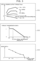
- the engine model 531 calculates the virtual engine output torque Teout from the virtual engine rotation speed Ne and the accelerator operation amount Pap. For example, a map as shown in FIG. 3 is used to calculate the virtual engine output torque Teout. This map defines the relation between the accelerator operation amount Pap, the virtual engine rotation speed Ne, and the virtual engine output torque Teout in a steady state. In this map, the virtual engine output torque Teout with respect to the virtual engine rotation speed Ne is given for each accelerator operation amount Pap.
- the torque characteristic shown in FIG. 3 may be set to characteristics assumed for a gasoline engine, or may be set to characteristics assumed for a diesel engine. In addition, the torque characteristics may be set to characteristics assumed for a natural intake engine, or may be set to characteristics assumed for a supercharged engine. In the data management device 500, the special vehicle characteristic data of such various torque characteristics may be prepared.
- the virtual engine output torque Teout calculated by the engine model 531 is input to the clutch model 532.
- the clutch model 532 calculates a torque transmission gain k.
- the torque transmission gain k is a gain for calculating the degree of torque transmission of the virtual clutch in accordance with the depression amount of the pseudo clutch pedal 28.
- the clutch model 532 has, for example, a map as shown in FIG. 3 . In this map, the torque transmission gain k is given to the clutch pedal depression amount Pc.
- Pc0 corresponds to a position where the clutch pedal depression amount Pc is 0%.
- Pc1 corresponds to a position of the play limit when the clutch pedal is depressed.
- Pc3 corresponds to a position where the clutch pedal depression amount Pc is 100%.
- Pc2 corresponds to the position of the play limit when returning the clutch pedal from Pc3.
- the clutch model 532 calculates the clutch output torque Tcout using the torque transmission gain k.
- the clutch output torque Tcout is torque output from the virtual clutch.
- the clutch model 532 calculates the clutch output torque Tcout from the virtual engine output torque Teout and the torque transmission gain k by the following equation (3).
- the clutch model 532 calculates the slip ratio Rslip.
- the slip ratio Rslip is used to calculate the virtual engine rotation speed Ne in the engine model 531.
- the MT model 533 calculates the gear ratio (transmission ratio) r.
- the gear ratio r is a gear ratio determined by the virtual gear stage GP in the virtual MT.
- the MT model 533 includes, for example, a map as illustrated in FIG. 3 . In this map, the gear ratio r is given to the virtual gear stage GP. As shown in FIG. 3 , the larger the virtual gear stage GP, the smaller the gear ratio r.
- the MT model 533 calculates the transmission output torque Tgout using the gear ratio r.
- the transmission output torque Tgout is the torque output from the virtual MT.
- the MT model 533 calculates the transmission output torque Tgout from the clutch output torque Tcout and the gear ratio r by the following equation (5).
- the axle/drive wheel model 534 calculates the drive wheel torque Tw using a predetermined reduction ratio rr.
- the reduction ratio rr is a fixed value determined by the mechanical structure from the virtual MT to the drive wheels 8.
- the overall reduction ratio R is obtained by multiplying the reduction ratio rr by the gear ratio r.
- the axle/drive wheel model 534 calculates the drive wheel torque Tw from the transmission output torque Tgout and the reduction ratio rr by the following equation (6).
- FIG. 4 is a block diagram illustrating an example of a configuration of the data management device 500.
- the data management device 500 includes a vehicle characteristic data DB 501, an unlock determination unit 502, and a vehicle characteristic data selection unit 503.
- the vehicle characteristic data DB 501 is a database in which a plurality of vehicle characteristic data is registered.
- the registered vehicle characteristic data includes standard vehicle characteristic data and special vehicle characteristic data.
- the standard vehicle characteristic data is vehicle characteristic data that can be selected by default.
- the special vehicle characteristic data is vehicle characteristic data that can be selected when a predetermined unlock condition is satisfied. A lock is not provided in the standard vehicle characteristic data, whereas a lock is provided in the special vehicle characteristic data.
- the registered special vehicle characteristic data is four sets of data A, data B, data C, and data D. Of these, the special vehicle characteristic data C and D remain locked, while the special vehicle characteristic data A and B are unlocked.
- the vehicle characteristic data registered in the vehicle characteristic data DB 501 is incorporated in the mode selection device 42.
- the standard mode corresponding to the standard vehicle characteristic data and the special mode corresponding to the unlocked special vehicle characteristic data are displayed on the touch panel of the mode selection device 42.
- two special modes corresponding to the special vehicle characteristic data A and B can be selected in the mode selection device 42.
- the unlock determination unit 502 determines whether the unlock condition is satisfied for each locked special vehicle characteristic data.
- the unlock condition is a condition requiring a predetermined action of the driver. A specific example of the unlock condition will be described later.
- the unlock determination unit 502 unlocks the special vehicle characteristic data that is requested to be unlocked by the driver and that satisfies the unlock condition. For example, when the unlock condition of the special vehicle characteristic data C is satisfied, the unlock determination unit 502 unlocks the special vehicle characteristic data C. When the special vehicle characteristic data C is unlocked, the special mode corresponding to the special vehicle characteristic data C can be selected by the mode selection device 42.
- the vehicle characteristic data selection unit 503 selects the vehicle characteristic data corresponding to the control mode selected by the mode selection device 42.
- the control mode selected by the mode selection device 42 is the MT mode.
- the vehicle characteristic data selection unit 503 selects the standard vehicle characteristic data.
- the vehicle characteristic data selection unit 503 selects the special vehicle characteristic data corresponding to the selected special mode.
- the data management device 500 sets the MT vehicle model included in the vehicle characteristic data selected by the vehicle characteristic data selection unit 503 in the motor control device 520.
- the data management device 500 also sets the sound data included in the selected vehicle characteristic data in the sound control device 510.
- FIG. 5 is a block diagram illustrating another example of the configuration of the data management device 500.
- the data management device 500 includes a communication unit 504, a download determination unit 505, a vehicle characteristic data DB 506, and a vehicle characteristic data selection unit 507.
- the communication unit 504 is connected to the server 60 on the network 100 using mobile communication.
- the server 60 includes a vehicle characteristic data DB 62.
- the vehicle characteristic data DB 62 is a database in which a plurality of special vehicle characteristic data is registered.
- the special vehicle characteristic data registered in the vehicle characteristic data DB 62 is four sets of data A, data B, data C, and data D.
- the download determination unit 505 determines whether the download condition is satisfied for each of the special vehicle characteristic data registered in the vehicle characteristic data DB 62.
- the download condition is a condition requiring a predetermined action of the driver, and the content thereof is the same as the unlock condition described above.
- the download determination unit 505 downloads, from the server 60, the special vehicle characteristic data that is requested to be downloaded by the driver and that satisfies the download condition. For example, when the download condition of the special vehicle characteristic data C is satisfied, the download determination unit 505 downloads the special vehicle characteristic data C.
- the special vehicle characteristic data on the server 60 can be used only when it is downloaded. Thus, the special vehicle characteristic data on the server 60 is substantially equal to being locked, and downloading it is substantially equal to unlocking it.
- the vehicle characteristic data DB 506 is a database in which the standard vehicle characteristic data and the special vehicle characteristic data downloaded from the server 60 are registered.
- the standard vehicle characteristic data is initially registered in the vehicle characteristic data DB 506.
- the vehicle characteristic data registered in the vehicle characteristic data DB 506 is incorporated in the mode selection device 42.
- the special vehicle characteristic data A and B are registered in the vehicle characteristic data DB 506. Therefore, the standard mode corresponding to the standard vehicle characteristic data and the two special modes corresponding to the special vehicle characteristic data A and B can be selected in the mode selection device 42.
- the vehicle characteristic data selection unit 507 selects, from the vehicle characteristic data DB 506, the vehicle characteristic data corresponding to the control mode selected by the mode selection device 42.
- the MT vehicle model included in the vehicle characteristic data selected by the vehicle characteristic data selection unit 507 is set in the motor control device 520.
- the sound data included in the selected vehicle characteristic data is set in the sound control device 510.
- FIG. 6 is a flowchart illustrating the process performed by the data management device 500.
- the process illustrated in this flowchart is a process common to the configuration illustrated in FIG. 4 and the configuration illustrated in FIG. 5 .
- the vehicle characteristic data available in the data management device 500 is only the standard vehicle characteristic data.
- the special vehicle characteristic data is unlocked. Then, the special vehicle characteristic data is also available in the data management device 500.
- the standard vehicle characteristic data has a lower driving force for the same vehicle speed in all gear stages as compared with the special vehicle characteristic data. This means that, in the standard vehicle characteristic data, output of the electric motor 2 with respect to the same operation amount of the accelerator pedal 22 is suppressed to be lower in all the operation positions of the pseudo H-type shifter 26 than in the special vehicle characteristic data.
- the unlock condition is a condition requiring a predetermined action of the driver.
- An example of the unlock condition requiring the driver's action is as follows.
- a first example of the unlock condition is that the degree of skill calculated from the driver's driving history reaches a predetermined passing value.
- the driving history includes, for example, parameters such as the total traveling distance in the MT mode, the traveling speed with respect to the set speed of the road, the magnitude of acceleration/deceleration, the shift timing, and the presence or absence of a shock when the clutch pedal is operated. From the sum of the scores given to these parameters, the degree of skill is calculated.
- the predetermined action of the driver in the first example is to increase the degree of skill to a passing value or more.
- a second example of the unlock condition is that a fee for the use of the special vehicle characteristic data is charged.
- the predetermined action of the driver in the second example is to charge a fee.
- the special vehicle characteristic data A and B are unlocked, but the special vehicle characteristic data C and D remain locked. This means that the special vehicle characteristic data C and D require a higher charge amount for unlocking them than the special vehicle characteristic data A and B.
- the MT vehicle models may be the same, and the charge amount may be changed depending on the difference in sound effect data. For example, a higher charge amount may be required for the special vehicle characteristic data having the sound effect data simulating a V8 cylinder engine than the special vehicle characteristic data having the sound effect data simulating the straight 4-cylinder engine.
- a pseudo sequential shifter may be provided instead of the pseudo H-type shifter.
- the pseudo clutch pedal may be omitted.
- the MT vehicle model may be a model of a clutch-pedal-free MT vehicle without a clutch pedal.
- the pseudo sequential shifter may be a paddle-type pseudo shifter or a lever-type pseudo shifter.
- downloading the special vehicle characteristic data from the server 60 may be performed by a mobile terminal such as a smartphone or a tablet carried by the driver.
- the downloaded special vehicle characteristic data may be transferred from the mobile terminal to the data management device 500.
- the battery electric vehicle includes an accelerator pedal, a shifter, a data management device that manages vehicle characteristic data, and a motor control device that controls an electric motor according to the vehicle characteristic data.
- the vehicle characteristic data is data configured to change an output characteristic of the electric motor with respect to an operation of the accelerator pedal according to an operation position of the shifter.
- the vehicle characteristic data includes standard vehicle characteristic data and special vehicle characteristic data that has been locked.
- the data management device is configured to unlock the special vehicle characteristic data when an unlock condition in which a predetermined action of a driver is used as a requirement is satisfied.
Landscapes
- Engineering & Computer Science (AREA)
- Transportation (AREA)
- Mechanical Engineering (AREA)
- Power Engineering (AREA)
- Automation & Control Theory (AREA)
- Chemical & Material Sciences (AREA)
- Combustion & Propulsion (AREA)
- Human Computer Interaction (AREA)
- Physics & Mathematics (AREA)
- Mathematical Physics (AREA)
- Electric Propulsion And Braking For Vehicles (AREA)
Abstract
The battery electric vehicle according to the present disclosure includes an accelerator pedal, a shifter, a data management device that manages vehicle characteristic data, and a motor control device that controls an electric motor according to the vehicle characteristic data. The vehicle characteristic data is data configured to change an output characteristic of the electric motor with respect to an operation of the accelerator pedal according to an operation position of the shifter. The vehicle characteristic data includes standard vehicle characteristic data and special vehicle characteristic data that has been locked. The data management device is configured to unlock the special vehicle characteristic data when an unlock condition in which a predetermined action of a driver is used as a requirement is satisfied.
Description
- The present disclosure relates to a battery electric vehicle that uses an electric motor as a power device for travel.
-
Japanese Unexamined Patent Application Publication No. 2021-118569 JP 2021-118569 A - One of the pleasures of driving an MT vehicle is the improvement in driving maneuvers. Even in a case where a driver can drive only a vehicle having low output and a vehicle having low torque characteristics when the driver is not used to driving, the driver may be able to drive a vehicle having high output or a vehicle having high torque characteristics due to the improvement in the driving maneuvers. Also, the vehicle having the high output and the vehicle having torque characteristics for a racing car or the like are generally expensive. However, possessing such a vehicle is also one pleasure for the driver of the MT vehicle. According to the battery electric vehicle described in
JP 2021-118569 A - The present disclosure has been made in view of the above issue. One object of the present disclosure is to provide a battery electric vehicle capable of not only causing the driver to enjoy driving feeling as if the driver drives the MT vehicle, but also giving the driver a sense of achievement due to the outcome of the driver's own action.
- The present disclosure provides a battery electric vehicle for achieving the above object. The battery electric vehicle according to the present disclosure includes an accelerator pedal, a shifter, a data management device that manages vehicle characteristic data, and a motor control device that controls an electric motor according to the vehicle characteristic data. The vehicle characteristic data is data configured to change an output characteristic of the electric motor with respect to an operation of the accelerator pedal according to an operation position of the shifter. The vehicle characteristic data includes standard vehicle characteristic data and special vehicle characteristic data that has been locked. The data management device is configured to unlock the special vehicle characteristic data when an unlock condition in which a predetermined action of a driver is used as a requirement is satisfied.
- With the battery electric vehicle according to the present disclosure, the standard vehicle characteristic data can be used even in an initial state, and the driver can enjoy the driving feeling as if the driver drives the MT vehicle due to the operation of the shifter being incorporated into a control of the electric motor. Furthermore, when the unlock condition is satisfied as a result of the driver's own action, the electric motor is controlled according to the special vehicle characteristic data, so that the driver can obtain a sense of achievement due to the enjoyment of the special driving feeling that cannot be obtained by the standard vehicle characteristic data.
- Features, advantages, and technical and industrial significance of exemplary embodiments of the invention will be described below with reference to the accompanying drawings, in which like signs denote like elements, and wherein:
-
FIG. 1 is a diagram schematically illustrating a configuration of a battery electric vehicle according to an embodiment of the present disclosure; -
FIG. 2 is a block diagram illustrating a configuration of a vehicle control device of the battery electric vehicle; -
FIG. 3 is a diagram illustrating an engine model, a clutch model, and a transmission model constituting an MT vehicle model; -
FIG. 4 is a block diagram illustrating an example of a configuration of a data management device; -
FIG. 5 is a block diagram illustrating another example of the configuration of the data management device; and -
FIG. 6 is a diagram illustrating a process performed by the data management device. -
FIG. 1 is a diagram schematically illustrating a configuration of a power system of a batteryelectric vehicle 10 according to the present embodiment. As shown inFIG. 1 , the batteryelectric vehicle 10 includes anelectric motor 2 as a power device for travel. Theelectric motor 2 is provided with arotation speed sensor 40 for detecting the rotation speed of theelectric motor 2. Anoutput shaft 3 of theelectric motor 2 is connected to one end of apropeller shaft 5 via agear mechanism 4. The other end of thepropeller shaft 5 is connected to adrive shaft 7 on the front side of the vehicle via a differential gear 6. The batteryelectric vehicle 10 includesdrive wheels 8 that are front wheels and drivenwheels 12 that are rear wheels. Thedrive wheels 8 are respectively provided at both ends of thedrive shaft 7. Each of thewheels wheel speed sensor 30. Only thewheel speed sensor 30 of the right rear wheel is shown inFIG. 1 . Thewheel speed sensor 30 is also used as a vehicle speed sensor for detecting the vehicle speed of the batteryelectric vehicle 10. - The battery
electric vehicle 10 is equipped with abattery 14 and aninverter 16. Thebattery 14 stores electric energy for driving theelectric motor 2. That is, the batteryelectric vehicle 10 is a battery electric vehicle (BEV) that travels with the electric energy stored in thebattery 14. Theinverter 16 converts direct-current (DC) power input from thebattery 14 at the time of acceleration into drive power of theelectric motor 2. Theinverter 16 converts the regenerative power input from theelectric motor 2 at the time of deceleration into DC power to charge thebattery 14. - The battery
electric vehicle 10 includes anaccelerator pedal 22 for the driver to input an acceleration request and abrake pedal 24 to input a braking request to the batteryelectric vehicle 10. Theaccelerator pedal 22 is provided with anaccelerator position sensor 32 for detecting an accelerator operation amount. Thebrake pedal 24 is provided with abrake position sensor 34 for detecting a brake depression amount. - The battery
electric vehicle 10 is equipped with a pseudo H-type shifter 26. The pseudo H-type shifter 26 has a configuration that simulates an H-type shifter included in a manual transmission (MT) vehicle. The pseudo H-type shifter 26 has positions corresponding to the gear stages of, for example, first speed, second speed, third speed, fourth speed, fifth speed, sixth speed, reverse speed, and neutral. The pseudo H-type shifter 26 is provided with ashift position sensor 36 that detects a gear stage by determining which position the pseudo H-type shifter 26 is in. - The battery
electric vehicle 10 is equipped with apseudo clutch pedal 28. Thepseudo clutch pedal 28 has a configuration simulating a clutch pedal included in the MT vehicle. When the driver wants to change the setting of the gear stage by the pseudo H-type shifter 26, the driver depresses thepseudo clutch pedal 28. When the change of the setting of the gear stage is completed, the driver stops depressing thepseudo clutch pedal 28 and returns thepseudo clutch pedal 28 to its original state. Thepseudo clutch pedal 28 is provided with aclutch position sensor 38 for detecting the amount of depression of thepseudo clutch pedal 28. - The battery
electric vehicle 10 is equipped with a pseudo enginerotation speed meter 44. The pseudo enginerotation speed meter 44 has a structure simulating an engine rotation speed meter included in a conventional vehicle. The pseudo enginerotation speed meter 44 may be a mechanical display, a liquid crystal display, or a projection display using a head-up display. When the pseudo enginerotation speed meter 44 is a liquid crystal display or a projection display, the revolution limit can be set to any value. The batteryelectric vehicle 10 is equipped with aspeaker 48 in the vehicle cabin. - The battery
electric vehicle 10 is equipped with amode selection device 42. Themode selection device 42 is a device that selects the traveling mode of the batteryelectric vehicle 10. The traveling modes of the batteryelectric vehicle 10 are roughly classified into MT mode and electric vehicle (EV) mode. The MT mode is a control mode for driving the batteryelectric vehicle 10 like an MT vehicle. The EV mode is a normal control mode for operating the batteryelectric vehicle 10 as a common battery electric vehicle. Furthermore, the MT mode can be divided into standard mode that can be selected by default and special mode that can be selected when a predetermined condition is satisfied. As themode selection device 42, for example, a touch panel capable of changing the display content by an external signal can be used. A display panel of a navigation device may be used for themode selection device 42. - The battery
electric vehicle 10 is equipped with avehicle control device 50. Sensors mounted on the batteryelectric vehicle 10 and devices to be controlled are connected to thevehicle control device 50 via an information communication network. Thevehicle control device 50 is typically an electronic control unit (ECU) mounted on the batteryelectric vehicle 10. Thevehicle control device 50 may be a combination of a plurality of ECUs. Thevehicle control device 50 includes aninterface 52, amemory 54, and aprocessor 56. An in-vehicle network is connected to theinterface 52. Thememory 54 includes a random access memory (RAM) for temporarily recording data and a read-only memory (ROM) for storing a program executable by theprocessor 56 and various data related to the program. The program is composed of a plurality of instructions. Theprocessor 56 reads the program and data from thememory 54 to execute them. Theprocessor 56 then generates control signals based on signals obtained from each sensor. -
FIG. 2 is a block diagram illustrating an example of a configuration of thevehicle control device 50. Thevehicle control device 50 receives inputs of signals from at least thewheel speed sensor 30, theaccelerator position sensor 32, thebrake position sensor 34, theshift position sensor 36, theclutch position sensor 38, therotation speed sensor 40, and themode selection device 42. Further, thevehicle control device 50 outputs signals to at least theinverter 16, the pseudo enginerotation speed meter 44, and thespeaker 48. Thevehicle control device 50 includes adata management device 500, asound control device 510, and amotor control device 520. Specifically, when the program stored in thememory 54 is executed by theprocessor 56, theprocessor 56 functions as at least thedata management device 500, thesound control device 510, and themotor control device 520. Hereinafter, each device constituting thevehicle control device 50 will be described. - The
data management device 500 is a device that manages vehicle characteristic data used for vehicle control in the MT mode. The vehicle characteristic data includes an MT vehicle model and sound data. The MT vehicle model is a model configured to change an output characteristic of theelectric motor 2 with respect to the operation of theaccelerator pedal 22 in accordance with an operation position of the pseudo H-type shifter 26. The sound data is data of sound effects such as exhaust sound of the engine, intake sound, and gear sound generated from the MT. The sound data is associated with the MT vehicle model. - The vehicle characteristic data includes standard vehicle characteristic data corresponding to the standard mode of the MT mode and special vehicle characteristic data corresponding to the special mode of the MT mode. When the MT mode selected by the
mode selection device 42 is the standard mode, thedata management device 500 sets the standard MT vehicle model included in the standard vehicle characteristic data to themotor control device 520, and sets the standard sound data included in the standard vehicle characteristic data to thesound control device 510. When the MT mode selected by themode selection device 42 is the special mode, thedata management device 500 sets the special MT vehicle model included in the special vehicle characteristic data to themotor control device 520, and sets the special sound data included in the special vehicle characteristic data to thesound control device 510. - The
sound control device 510 is a device that controls thespeaker 48 in accordance with the sound data set by thedata management device 500. Depending on whether the sound data is standard sound data or special sound data, and when there is a plurality of special sound data, the volume, the pitch, or the type of sound of the sound effect emitted from thespeaker 48 is different for each special sound data. - The
motor control device 520 is a device that controls theelectric motor 2 by pulse width modulation (PWM) control of theinverter 16. Themotor control device 520 includes anMT vehicle model 530, a required motortorque calculation unit 540, a motortorque command map 550, and an outputtorque switching unit 560. TheMT vehicle model 530 is an MT vehicle model set by thedata management device 500 in accordance with a selection made by themode selection device 42. Signals from thewheel speed sensor 30, theaccelerator position sensor 32, theshift position sensor 36, theclutch position sensor 38, therotation speed sensor 40, and themode selection device 42 are input to themotor control device 520. Themotor control device 520 processes signals from these sensors. Themotor control device 520 then calculates a motor torque command value to perform PWM control on theinverter 16. - There are two types of calculation of the motor torque by the motor control device 520: calculation using the
MT vehicle model 530 and the required motortorque calculation unit 540; and calculation using the motortorque command map 550. TheMT vehicle model 530 and the required motortorque calculation unit 540 are used to calculate the motor torque when the batteryelectric vehicle 10 is driven in the MT mode. The motortorque command map 550 is used to calculate the motor torque when the batteryelectric vehicle 10 is driven in the EV mode. The motor torque to be used is determined by the outputtorque switching unit 560. - The
MT vehicle model 530 is a model that calculates the drive wheel torque that should be obtained by operating theaccelerator pedal 22, the pseudo H-type shifter 26, and the pseudoclutch pedal 28, assuming that batteryelectric vehicle 10 is an MT vehicle. The engine, the clutch, and the manual transmission (MT) virtually implemented by theMT vehicle model 530 are referred to as a virtual engine, a virtual clutch, and a virtual MT, respectively. The configuration of theMT vehicle model 530 will be described later. - The required motor
torque calculation unit 540 converts the drive wheel torque Tw calculated by theMT vehicle model 530 into a required motor torque Tmt. The required motor torque Tmt is the motor torque required to achieve the drive wheel torque Tw calculated by theMT vehicle model 530. In order to convert the drive wheel torque Tw into the required motor torque Tmt, a reduction ratio from theoutput shaft 3 of theelectric motor 2 to thedrive wheels 8 is used. - The motor
torque command map 550 is a map for determining the motor torque from the accelerator operation amount and the rotation speed of theelectric motor 2. A signal of theaccelerator position sensor 32 and a signal of therotation speed sensor 40 are input to each parameter of the motortorque command map 550. A motor torque Tev corresponding to these signals is output from the motortorque command map 550. In the EV mode, even when the driver operates the pseudo H-type shifter 26 or the pseudoclutch pedal 28, the operation is not incorporated in the driving of the batteryelectric vehicle 10. - The output
torque switching unit 560 operates in accordance with the control mode selected by themode selection device 42. When the EV mode is selected by themode selection device 42, the outputtorque switching unit 560 is connected to the motortorque command map 550 and outputs the motor torque Tev as the motor torque command value Tm to theinverter 16. When the MT mode is selected by themode selection device 42, the outputtorque switching unit 560 switches the connection destination to the required motortorque calculation unit 540, and outputs the motor torque Tmt to theinverter 16 as the motor torque command value Tm. - The
MT vehicle model 530 will now be described. TheMT vehicle model 530 includes anengine model 531, aclutch model 532, anMT model 533, and an axle/drive wheel model 534. In theengine model 531, the virtual engine is modeled. In theclutch model 532, the virtual clutch is modeled. In theMT model 533, the virtual MT is modeled. In the axle/drive wheel model 534, a virtual torque transmission system from the axle to the drive wheels is modeled. - The
MT vehicle model 530 is calculated by using signals obtained by the sensors. The accelerator operation amount Pap detected by theaccelerator position sensor 32 is input to theengine model 531. The clutch pedal depression amount Pc detected by theclutch position sensor 38 is input to theclutch model 532. The shift position Sp detected by theshift position sensor 36 is input to theMT model 533. The vehicle speed Vw detected by thewheel speed sensor 30 is used in a plurality of models. Furthermore, calculation results are mutually used between the models. TheMT vehicle model 530 calculates the drive wheel torque Tw and the virtual engine rotation speed Ne based on these input signals. - The
engine model 531 calculates a virtual engine rotation speed Ne and a virtual engine power torque Teout. Theengine model 531 includes a model for calculating the virtual engine rotation speed Ne and a model for calculating the virtual engine output torque Teout. For example, the model represented by the following equation (1) is used to calculate the virtual engine rotation speed Ne. In the following equation (1), the virtual engine rotation speed Ne is calculated from the rotation speed Nw of thewheel 8, the overall reduction ratio R, and the slip-rate Rslip of the virtual clutch.
Equation 1
- In Equation (1), the rotation speed Nw of the
wheel 8 is detected by thewheel speed sensor 30. The overall reduction ratio R is calculated from the gear ratio (transmission ratio) r calculated by theMT model 533 described later and the reduction ratio defined by the axle/drive wheel model 534. The slip-rate Rslip is calculated by a later-describedclutch model 532. The virtual engine rotation speed Ne is displayed on the pseudo enginerotation speed meter 44 when the MT mode is selected. - Note that Equation (1) is a formula for calculating the virtual engine rotation speed Ne when the virtual engine and the virtual MT are connected to each other by the virtual clutch. When the virtual clutch is disengaged, the virtual engine torque Te generated in the virtual engine may be considered to be used to increase the virtual engine rotation speed Ne. The virtual engine torque Te is the torque obtained by adding the torque caused by the moment of inertia to the virtual engine output torque Teout. When the virtual clutch is disengaged, the virtual engine output torque Teout is zero. Therefore, when the virtual clutch is disengaged, the
engine model 531 calculates the virtual engine rotation speed Ne using the virtual engine torque Te and the moment of inertia J of the virtual engine according to the following equation (2). In calculating the virtual engine torque Te, a map having the accelerator operation amount Pap as a parameter is used.
Equation 2
- The
engine model 531 calculates the virtual engine output torque Teout from the virtual engine rotation speed Ne and the accelerator operation amount Pap. For example, a map as shown inFIG. 3 is used to calculate the virtual engine output torque Teout. This map defines the relation between the accelerator operation amount Pap, the virtual engine rotation speed Ne, and the virtual engine output torque Teout in a steady state. In this map, the virtual engine output torque Teout with respect to the virtual engine rotation speed Ne is given for each accelerator operation amount Pap. The torque characteristic shown inFIG. 3 may be set to characteristics assumed for a gasoline engine, or may be set to characteristics assumed for a diesel engine. In addition, the torque characteristics may be set to characteristics assumed for a natural intake engine, or may be set to characteristics assumed for a supercharged engine. In thedata management device 500, the special vehicle characteristic data of such various torque characteristics may be prepared. The virtual engine output torque Teout calculated by theengine model 531 is input to theclutch model 532. - The
clutch model 532 calculates a torque transmission gain k. The torque transmission gain k is a gain for calculating the degree of torque transmission of the virtual clutch in accordance with the depression amount of the pseudoclutch pedal 28. Theclutch model 532 has, for example, a map as shown inFIG. 3 . In this map, the torque transmission gain k is given to the clutch pedal depression amount Pc. InFIG. 3 , Pc0 corresponds to a position where the clutch pedal depression amount Pc is 0%. InFIG. 3 , Pc1 corresponds to a position of the play limit when the clutch pedal is depressed. InFIG. 3 , Pc3 corresponds to a position where the clutch pedal depression amount Pc is 100%. InFIG. 3 , Pc2 corresponds to the position of the play limit when returning the clutch pedal from Pc3. - The
clutch model 532 calculates the clutch output torque Tcout using the torque transmission gain k. The clutch output torque Tcout is torque output from the virtual clutch. For example, theclutch model 532 calculates the clutch output torque Tcout from the virtual engine output torque Teout and the torque transmission gain k by the following equation (3). The clutch output torque Tcout calculated by theclutch model 532 is input to theMT model 533.
Equation 3
- The
clutch model 532 calculates the slip ratio Rslip. The slip ratio Rslip is used to calculate the virtual engine rotation speed Ne in theengine model 531. The slip ratio Rslip can be calculated using a map in which the slip ratio Rslip is given to the clutch pedal depression amount Pc in the same manner as the torque transmission gain k. Instead of such a map, the slip ratio Rslip may be calculated from the torque transmission gain k by the following equation (4) representing the relation between the slip ratio Rslip and the torque transmission gain k.
Equation 4
- The
MT model 533 calculates the gear ratio (transmission ratio) r. The gear ratio r is a gear ratio determined by the virtual gear stage GP in the virtual MT. TheMT model 533 includes, for example, a map as illustrated inFIG. 3 . In this map, the gear ratio r is given to the virtual gear stage GP. As shown inFIG. 3 , the larger the virtual gear stage GP, the smaller the gear ratio r. TheMT model 533 calculates the transmission output torque Tgout using the gear ratio r. The transmission output torque Tgout is the torque output from the virtual MT. For example, theMT model 533 calculates the transmission output torque Tgout from the clutch output torque Tcout and the gear ratio r by the following equation (5). The transmission output torque Tgout calculated by theMT model 533 is input to the axle/drive wheel model 534.
Equation 5
- The axle/
drive wheel model 534 calculates the drive wheel torque Tw using a predetermined reduction ratio rr. The reduction ratio rr is a fixed value determined by the mechanical structure from the virtual MT to thedrive wheels 8. The overall reduction ratio R is obtained by multiplying the reduction ratio rr by the gear ratio r. For example, the axle/drive wheel model 534 calculates the drive wheel torque Tw from the transmission output torque Tgout and the reduction ratio rr by the following equation (6). The drive wheel torque Tw calculated by the axle/drive wheel model 534 is output to the required motortorque calculation unit 540.
Equation 6
- Next, details of the
data management device 500 will be described with reference to the drawings.FIG. 4 is a block diagram illustrating an example of a configuration of thedata management device 500. In the example illustrated inFIG. 4 , thedata management device 500 includes a vehiclecharacteristic data DB 501, anunlock determination unit 502, and a vehicle characteristicdata selection unit 503. - The vehicle
characteristic data DB 501 is a database in which a plurality of vehicle characteristic data is registered. The registered vehicle characteristic data includes standard vehicle characteristic data and special vehicle characteristic data. The standard vehicle characteristic data is vehicle characteristic data that can be selected by default. The special vehicle characteristic data is vehicle characteristic data that can be selected when a predetermined unlock condition is satisfied. A lock is not provided in the standard vehicle characteristic data, whereas a lock is provided in the special vehicle characteristic data. In the example illustrated inFIG. 4 , the registered special vehicle characteristic data is four sets of data A, data B, data C, and data D. Of these, the special vehicle characteristic data C and D remain locked, while the special vehicle characteristic data A and B are unlocked. - The vehicle characteristic data registered in the vehicle
characteristic data DB 501 is incorporated in themode selection device 42. Among the registered vehicle characteristic data, the standard mode corresponding to the standard vehicle characteristic data and the special mode corresponding to the unlocked special vehicle characteristic data are displayed on the touch panel of themode selection device 42. In the example shown inFIG. 4 , two special modes corresponding to the special vehicle characteristic data A and B can be selected in themode selection device 42. - The
unlock determination unit 502 determines whether the unlock condition is satisfied for each locked special vehicle characteristic data. The unlock condition is a condition requiring a predetermined action of the driver. A specific example of the unlock condition will be described later. Theunlock determination unit 502 unlocks the special vehicle characteristic data that is requested to be unlocked by the driver and that satisfies the unlock condition. For example, when the unlock condition of the special vehicle characteristic data C is satisfied, theunlock determination unit 502 unlocks the special vehicle characteristic data C. When the special vehicle characteristic data C is unlocked, the special mode corresponding to the special vehicle characteristic data C can be selected by themode selection device 42. - The vehicle characteristic
data selection unit 503 selects the vehicle characteristic data corresponding to the control mode selected by themode selection device 42. The control mode selected by themode selection device 42 is the MT mode. When the MT mode is the standard mode, the vehicle characteristicdata selection unit 503 selects the standard vehicle characteristic data. When the selected MT mode is the special mode, the vehicle characteristicdata selection unit 503 selects the special vehicle characteristic data corresponding to the selected special mode. Thedata management device 500 sets the MT vehicle model included in the vehicle characteristic data selected by the vehicle characteristicdata selection unit 503 in themotor control device 520. Thedata management device 500 also sets the sound data included in the selected vehicle characteristic data in thesound control device 510. -
FIG. 5 is a block diagram illustrating another example of the configuration of thedata management device 500. In the example illustrated inFIG. 5 , thedata management device 500 includes acommunication unit 504, adownload determination unit 505, a vehiclecharacteristic data DB 506, and a vehicle characteristicdata selection unit 507. - The
communication unit 504 is connected to theserver 60 on thenetwork 100 using mobile communication. Theserver 60 includes a vehiclecharacteristic data DB 62. The vehiclecharacteristic data DB 62 is a database in which a plurality of special vehicle characteristic data is registered. In the example illustrated inFIG. 5 , the special vehicle characteristic data registered in the vehiclecharacteristic data DB 62 is four sets of data A, data B, data C, and data D. - The
download determination unit 505 determines whether the download condition is satisfied for each of the special vehicle characteristic data registered in the vehiclecharacteristic data DB 62. The download condition is a condition requiring a predetermined action of the driver, and the content thereof is the same as the unlock condition described above. Thedownload determination unit 505 downloads, from theserver 60, the special vehicle characteristic data that is requested to be downloaded by the driver and that satisfies the download condition. For example, when the download condition of the special vehicle characteristic data C is satisfied, thedownload determination unit 505 downloads the special vehicle characteristic data C. The special vehicle characteristic data on theserver 60 can be used only when it is downloaded. Thus, the special vehicle characteristic data on theserver 60 is substantially equal to being locked, and downloading it is substantially equal to unlocking it. - The vehicle
characteristic data DB 506 is a database in which the standard vehicle characteristic data and the special vehicle characteristic data downloaded from theserver 60 are registered. The standard vehicle characteristic data is initially registered in the vehiclecharacteristic data DB 506. The vehicle characteristic data registered in the vehiclecharacteristic data DB 506 is incorporated in themode selection device 42. In the example illustrated inFIG. 5 , the special vehicle characteristic data A and B are registered in the vehiclecharacteristic data DB 506. Therefore, the standard mode corresponding to the standard vehicle characteristic data and the two special modes corresponding to the special vehicle characteristic data A and B can be selected in themode selection device 42. - The vehicle characteristic
data selection unit 507 selects, from the vehiclecharacteristic data DB 506, the vehicle characteristic data corresponding to the control mode selected by themode selection device 42. The MT vehicle model included in the vehicle characteristic data selected by the vehicle characteristicdata selection unit 507 is set in themotor control device 520. The sound data included in the selected vehicle characteristic data is set in thesound control device 510. -
FIG. 6 is a flowchart illustrating the process performed by thedata management device 500. The process illustrated in this flowchart is a process common to the configuration illustrated inFIG. 4 and the configuration illustrated inFIG. 5 . Here, it is assumed that one set is available for each of the standard vehicle characteristic data and the special vehicle characteristic data. - When the unlock condition is not satisfied, the vehicle characteristic data available in the
data management device 500 is only the standard vehicle characteristic data. When the unlock condition is satisfied, the special vehicle characteristic data is unlocked. Then, the special vehicle characteristic data is also available in thedata management device 500. In the example shown inFIG. 6 , the standard vehicle characteristic data has a lower driving force for the same vehicle speed in all gear stages as compared with the special vehicle characteristic data. This means that, in the standard vehicle characteristic data, output of theelectric motor 2 with respect to the same operation amount of theaccelerator pedal 22 is suppressed to be lower in all the operation positions of the pseudo H-type shifter 26 than in the special vehicle characteristic data. - According to the standard vehicle characteristic data and the special vehicle characteristic data as illustrated in
FIG. 6 , when the standard vehicle characteristic data is selected, the output of the driving force can be suppressed, and thus the driving can be performed without anxiety. When the special vehicle characteristic data is unlocked so that it can be selected, the driver can obtain a new drivability experience by driving with a higher driving force. The unlock condition is a condition requiring a predetermined action of the driver. An example of the unlock condition requiring the driver's action is as follows. - A first example of the unlock condition is that the degree of skill calculated from the driver's driving history reaches a predetermined passing value. The driving history includes, for example, parameters such as the total traveling distance in the MT mode, the traveling speed with respect to the set speed of the road, the magnitude of acceleration/deceleration, the shift timing, and the presence or absence of a shock when the clutch pedal is operated. From the sum of the scores given to these parameters, the degree of skill is calculated. The predetermined action of the driver in the first example is to increase the degree of skill to a passing value or more. By using new vehicle characteristic data as a result of improved degree of driving skill, it is possible to obtain a sense of achievement by enjoying a special driving sensation that cannot be obtained by the standard vehicle characteristic data.
- When there is a plurality of special vehicle characteristic data and the maximum driving force is different for each special vehicle characteristic data, the higher the driving force is, the higher the passing value of the degree of skill that is the unlock condition is set. In addition, when there are special vehicle characteristic data having output characteristics of a high rotation type and special vehicle characteristic data having output characteristics of a medium and low speed type, a higher passing value of the degree of skill is set for the high rotation type. When there is special vehicle characteristic data having output characteristics for a circuit, the passing value of the degree of skill may be set to be specially high. In the example shown in
FIG. 4 and the example shown inFIG. 5 , the special vehicle characteristic data A and B are unlocked, but the special vehicle characteristic data C and D remain locked. This means that the special vehicle characteristic data C and D require higher degree of driving skills for unlocking them than the special vehicle characteristic data A and B. - A second example of the unlock condition is that a fee for the use of the special vehicle characteristic data is charged. The predetermined action of the driver in the second example is to charge a fee. There is a need to prepare the necessary funds for charging a fee. It is necessary to make appropriate efforts in accordance with the amount of funds to be prepared. Therefore, it can be said that charging a fee is one of the actions that leads to the sense of achievement.
- When there is a plurality of special vehicle characteristic data and the maximum driving force is different for each special vehicle characteristic data, the higher the driving force is, the higher the charge amount that is the unlock condition is set. In the example shown in
FIG. 4 and the example shown inFIG. 5 , the special vehicle characteristic data A and B are unlocked, but the special vehicle characteristic data C and D remain locked. This means that the special vehicle characteristic data C and D require a higher charge amount for unlocking them than the special vehicle characteristic data A and B. It should be noted that the MT vehicle models may be the same, and the charge amount may be changed depending on the difference in sound effect data. For example, a higher charge amount may be required for the special vehicle characteristic data having the sound effect data simulating a V8 cylinder engine than the special vehicle characteristic data having the sound effect data simulating the straight 4-cylinder engine. - In the above embodiment, a pseudo sequential shifter may be provided instead of the pseudo H-type shifter. Further, the pseudo clutch pedal may be omitted. In this case, the MT vehicle model may be a model of a clutch-pedal-free MT vehicle without a clutch pedal. The pseudo sequential shifter may be a paddle-type pseudo shifter or a lever-type pseudo shifter.
- In the configuration of the
data management device 500 illustrated inFIG. 5 , downloading the special vehicle characteristic data from theserver 60 may be performed by a mobile terminal such as a smartphone or a tablet carried by the driver. The downloaded special vehicle characteristic data may be transferred from the mobile terminal to thedata management device 500. - The battery electric vehicle according to the present disclosure includes an accelerator pedal, a shifter, a data management device that manages vehicle characteristic data, and a motor control device that controls an electric motor according to the vehicle characteristic data. The vehicle characteristic data is data configured to change an output characteristic of the electric motor with respect to an operation of the accelerator pedal according to an operation position of the shifter. The vehicle characteristic data includes standard vehicle characteristic data and special vehicle characteristic data that has been locked. The data management device is configured to unlock the special vehicle characteristic data when an unlock condition in which a predetermined action of a driver is used as a requirement is satisfied.
Claims (5)
- A battery electric vehicle that uses an electric motor as a power device for traveling, the battery electric vehicle comprising:an accelerator pedal;a shifter;a data management device for managing vehicle characteristic data configured to change an output characteristic of the electric motor with respect to an operation of the accelerator pedal according to an operation position of the shifter; anda motor control device for controlling the electric motor according to the vehicle characteristic data, wherein:the vehicle characteristic data includes standard vehicle characteristic data and special vehicle characteristic data that has been locked; andthe data management device is configured to unlock the special vehicle characteristic data when an unlock condition in which a predetermined action of a driver is used as a requirement is satisfied.
- The battery electric vehicle according to claim 1, wherein in the standard vehicle characteristic data, output of the electric motor with respect to the same operation amount of the accelerator pedal is suppressed to be lower in all the operation positions of the shifter than in the special vehicle characteristic data.
- The battery electric vehicle according to claim 1, wherein the predetermined action includes increasing a degree of skill calculated from a driving history of the driver to a predetermined passing value or more.
- The battery electric vehicle according to claim 1, wherein the predetermined action includes charging a fee for use of the special vehicle characteristic data.
- The battery electric vehicle according to any one of claims 1 to 4, wherein:the special vehicle characteristic data is present in a server on a network; andunlocking the special vehicle characteristic data includes downloading the special vehicle characteristic data from the server.
Applications Claiming Priority (1)
| Application Number | Priority Date | Filing Date | Title |
|---|---|---|---|
| JP2022206898A JP7424464B1 (en) | 2022-12-23 | 2022-12-23 | Electric car |
Publications (1)
| Publication Number | Publication Date |
|---|---|
| EP4389498A1 true EP4389498A1 (en) | 2024-06-26 |
Family
ID=89121541
Family Applications (1)
| Application Number | Title | Priority Date | Filing Date |
|---|---|---|---|
| EP23214648.0A Pending EP4389498A1 (en) | 2022-12-23 | 2023-12-06 | Battery electric vehicle |
Country Status (4)
| Country | Link |
|---|---|
| US (1) | US12496910B2 (en) |
| EP (1) | EP4389498A1 (en) |
| JP (1) | JP7424464B1 (en) |
| CN (1) | CN118238627A (en) |
Families Citing this family (2)
| Publication number | Priority date | Publication date | Assignee | Title |
|---|---|---|---|---|
| JP2025077143A (en) * | 2023-11-06 | 2025-05-19 | トヨタ自動車株式会社 | Vehicle control device |
| JP2025078243A (en) * | 2023-11-08 | 2025-05-20 | トヨタ自動車株式会社 | Electric Vehicles |
Citations (3)
| Publication number | Priority date | Publication date | Assignee | Title |
|---|---|---|---|---|
| EP2557012A1 (en) * | 2011-06-02 | 2013-02-13 | Toyota Jidosha Kabushiki Kaisha | Control device of vehicle |
| US20210053487A1 (en) * | 2019-08-22 | 2021-02-25 | Ford Global Technologies, Llc | Electric vehicle with selectable vehicle profiles |
| US20210229550A1 (en) * | 2020-01-23 | 2021-07-29 | Toyota Jidosha Kabushiki Kaisha | Electric vehicle |
Family Cites Families (10)
| Publication number | Priority date | Publication date | Assignee | Title |
|---|---|---|---|---|
| RU2443586C2 (en) | 2006-09-15 | 2012-02-27 | Вольво Ластвагнар Аб | Method of adapting automatic mechanical transmission of large capacity trucks |
| JP2014213633A (en) | 2013-04-23 | 2014-11-17 | トヨタ自動車株式会社 | Control device for hybrid vehicle |
| US9428197B2 (en) * | 2014-02-04 | 2016-08-30 | Ford Global Technology, Llc | Method and apparatus for persistent transferrable customizable vehicle settings |
| JP6491686B2 (en) * | 2017-03-28 | 2019-03-27 | 株式会社Subaru | vehicle |
| JP2020153292A (en) | 2019-03-20 | 2020-09-24 | 株式会社Subaru | Vehicle control system and vehicle control method |
| US11679757B2 (en) * | 2019-12-30 | 2023-06-20 | Baidu Usa Llc | Control assistant system to align driving and riding experience between gasoline and electric vehicles |
| US20210291784A1 (en) | 2020-03-19 | 2021-09-23 | International Business Machines Corporation | Verifying novice driver supervision |
| KR20220039934A (en) * | 2020-09-22 | 2022-03-30 | 현대자동차주식회사 | A system and method of electric vehicle for virtual simulation of internal combustion engine vehicle characteristics |
| US12060071B2 (en) * | 2021-11-24 | 2024-08-13 | Rivian Ip Holdings, Llc | Performance limiter |
| JP2024039985A (en) * | 2022-09-12 | 2024-03-25 | 株式会社Subaru | Electric car |
-
2022
- 2022-12-23 JP JP2022206898A patent/JP7424464B1/en active Active
-
2023
- 2023-08-30 US US18/458,223 patent/US12496910B2/en active Active
- 2023-09-27 CN CN202311264228.7A patent/CN118238627A/en active Pending
- 2023-12-06 EP EP23214648.0A patent/EP4389498A1/en active Pending
Patent Citations (4)
| Publication number | Priority date | Publication date | Assignee | Title |
|---|---|---|---|---|
| EP2557012A1 (en) * | 2011-06-02 | 2013-02-13 | Toyota Jidosha Kabushiki Kaisha | Control device of vehicle |
| US20210053487A1 (en) * | 2019-08-22 | 2021-02-25 | Ford Global Technologies, Llc | Electric vehicle with selectable vehicle profiles |
| US20210229550A1 (en) * | 2020-01-23 | 2021-07-29 | Toyota Jidosha Kabushiki Kaisha | Electric vehicle |
| JP2021118569A (en) | 2020-01-23 | 2021-08-10 | トヨタ自動車株式会社 | Electric vehicle |
Also Published As
| Publication number | Publication date |
|---|---|
| JP7424464B1 (en) | 2024-01-30 |
| CN118238627A (en) | 2024-06-25 |
| US20240208336A1 (en) | 2024-06-27 |
| US12496910B2 (en) | 2025-12-16 |
| JP2024090788A (en) | 2024-07-04 |
Similar Documents
| Publication | Publication Date | Title |
|---|---|---|
| CN114056115B (en) | electric car | |
| JP7380478B2 (en) | Electric car | |
| JP7827089B2 (en) | Electric vehicle control device | |
| CN114056121A (en) | Electric automobile | |
| EP4389498A1 (en) | Battery electric vehicle | |
| JP7294271B2 (en) | Electric car | |
| JP2024038489A (en) | Electric car | |
| EP4574572A1 (en) | Vehicle management system and battery electric vehicle | |
| CN119953270A (en) | Electric vehicles and control systems | |
| EP4406799A1 (en) | Battery electric vehicle | |
| EP4563398A1 (en) | Vehicle management system and battery electric vehicle | |
| EP4610091A1 (en) | Electric vehicle | |
| EP4681974A2 (en) | Vehicle | |
| US20250214447A1 (en) | Battery electric vehicle and storage medium | |
| US12409739B2 (en) | Battery electric vehicle | |
| US20250145146A1 (en) | Battery electric vehicle | |
| US20260116214A1 (en) | Battery electric vehicle, control device, and control method | |
| US20250262947A1 (en) | Electric vehicle and control device | |
| JP2026000740A (en) | electric vehicles | |
| CN121989949A (en) | Battery electric vehicles |
Legal Events
| Date | Code | Title | Description |
|---|---|---|---|
| PUAI | Public reference made under article 153(3) epc to a published international application that has entered the european phase |
Free format text: ORIGINAL CODE: 0009012 |
|
| STAA | Information on the status of an ep patent application or granted ep patent |
Free format text: STATUS: REQUEST FOR EXAMINATION WAS MADE |
|
| 17P | Request for examination filed |
Effective date: 20231206 |
|
| AK | Designated contracting states |
Kind code of ref document: A1 Designated state(s): AL AT BE BG CH CY CZ DE DK EE ES FI FR GB GR HR HU IE IS IT LI LT LU LV MC ME MK MT NL NO PL PT RO RS SE SI SK SM TR |