EP4389488A1 - Power take-off transmission device and crane - Google Patents
Power take-off transmission device and crane Download PDFInfo
- Publication number
- EP4389488A1 EP4389488A1 EP22862519.0A EP22862519A EP4389488A1 EP 4389488 A1 EP4389488 A1 EP 4389488A1 EP 22862519 A EP22862519 A EP 22862519A EP 4389488 A1 EP4389488 A1 EP 4389488A1
- Authority
- EP
- European Patent Office
- Prior art keywords
- electric motor
- power take
- transmission device
- mounting
- input end
- Prior art date
- Legal status (The legal status is an assumption and is not a legal conclusion. Google has not performed a legal analysis and makes no representation as to the accuracy of the status listed.)
- Granted
Links
Images

Classifications
-
- B—PERFORMING OPERATIONS; TRANSPORTING
- B66—HOISTING; LIFTING; HAULING
- B66C—CRANES; LOAD-ENGAGING ELEMENTS OR DEVICES FOR CRANES, CAPSTANS, WINCHES, OR TACKLES
- B66C13/00—Other constructional features or details
- B66C13/18—Control systems or devices
-
- B—PERFORMING OPERATIONS; TRANSPORTING
- B60—VEHICLES IN GENERAL
- B60K—ARRANGEMENT OR MOUNTING OF PROPULSION UNITS OR OF TRANSMISSIONS IN VEHICLES; ARRANGEMENT OR MOUNTING OF PLURAL DIVERSE PRIME-MOVERS IN VEHICLES; AUXILIARY DRIVES FOR VEHICLES; INSTRUMENTATION OR DASHBOARDS FOR VEHICLES; ARRANGEMENTS IN CONNECTION WITH COOLING, AIR INTAKE, GAS EXHAUST OR FUEL SUPPLY OF PROPULSION UNITS IN VEHICLES
- B60K25/00—Auxiliary drives
- B60K25/06—Auxiliary drives from the transmission power take-off
-
- F—MECHANICAL ENGINEERING; LIGHTING; HEATING; WEAPONS; BLASTING
- F16—ENGINEERING ELEMENTS AND UNITS; GENERAL MEASURES FOR PRODUCING AND MAINTAINING EFFECTIVE FUNCTIONING OF MACHINES OR INSTALLATIONS; THERMAL INSULATION IN GENERAL
- F16D—COUPLINGS FOR TRANSMITTING ROTATION; CLUTCHES; BRAKES
- F16D1/00—Couplings for rigidly connecting two coaxial shafts or other movable machine elements
- F16D1/02—Couplings for rigidly connecting two coaxial shafts or other movable machine elements for connecting two abutting shafts or the like
- F16D1/04—Couplings for rigidly connecting two coaxial shafts or other movable machine elements for connecting two abutting shafts or the like with clamping hub; with hub and longitudinal key
Definitions
- the electric motor output end is a spline sleeve
- the pump input end is a spline shaft
- the spline sleeve is sleeved on an outside of the spline shaft.
- the mounting holes provided on the auxiliary rack 140 are long holes to ensure that the positions of the auxiliary rack 140 are adjustable in the front, back, left and right.
- the auxiliary rack 140 is welded and fixed to the machine frame by a support board with adjustable upper and lower positions, and the support plate can be provided in the air.
- the auxiliary rack 140 can solve the problem of the power take-off transmission device's cantilever being too long, thus increasing the system rigidity and reducing vibration.
Landscapes
- Engineering & Computer Science (AREA)
- Mechanical Engineering (AREA)
- General Engineering & Computer Science (AREA)
- Chemical & Material Sciences (AREA)
- Combustion & Propulsion (AREA)
- Transportation (AREA)
- Automation & Control Theory (AREA)
- Connection Of Motors, Electrical Generators, Mechanical Devices, And The Like (AREA)
Abstract
Description
- The present application relates to the technical field of engineering machinery, and in particular to a power take-off transmission device and a crane.
- In related existing technologies, the traditional truck crane consumes a lot of fuel during loading operations, has low conversion efficiency and low energy utilization rate.
- The electric motor and the oil pump are important components of the power take-off transmission device. Conventionally, the electric motor is connected to the oil pump by a transmission shaft or coupling. Both the input end of the electric motor and the output end of the electric motor have transmission shafts, or the input end of the electric motor is the transmission shaft and the output end of the electric motor is the end coupling. When the output end of the electric motor and the input end of the oil pump are connected by a transmission shaft or coupling, the transmission efficiency decreases. Moreover, it is difficult to ensure that the output end of the electric motor and the input end of the oil pump are coaxial, which can easily lead to vibration, abnormal noise and oil leakage problems.
- In view of this, a first object according to the present application is to provide a power take-off transmission device, which solves or improves the technical problem in the background art that it is difficult to ensure that the output end of the electric motor and the input end of the oil pump are coaxial.
- The first aspect according to the present application provides a power take-off transmission device. The power take-off transmission device includes an electric motor including an electric motor output end, a hydraulic pump including a pump input end, a mounting rack provided with a mounting stop penetrating the mounting rack in an axial direction, and the electric motor output end and the pump input end are connected to each other via the mounting stop.
- The power take-off transmission device provided in the first aspect according to the present application does not need to be connected by a transmission shaft or coupling, and the electric motor output end and the pump input end are connected to each other via the mounting stop. The mounting stop forms a radial limit to the electric motor output end and/or the pump input end, thereby ensuring that the electric motor output end and the pump input end are coaxially installed in the axial direction, which can avoid vibration, abnormal noise and oil leakage problems, thereby ensuring the reliability of the power take-off transmission device.
- Combining the first aspect, in a possible implementation method, the electric motor further includes an electric motor housing, and the electric motor housing is connected to the mounting rack.
- Combining the first aspect, in a possible implementation method, the mounting rack is provided with a plurality of counterbore holes along a circumferential direction of the mounting stop for respectively passing fasteners to connect the mounting rack and the electric motor housing.
- Combining the first aspect, in a possible implementation method, the hydraulic pump further includes a pump housing, and the pump housing is connected to the mounting rack.
- Combining the first aspect, in a possible implementation method, the mounting rack is provided with a plurality of connecting holes along a circumferential direction of the mounting stop for respectively passing fasteners to connect the mounting rack and the pump housing.
- Combining the first aspect, in a possible implementation method, the electric motor output end and the pump input end are inserted and matched in a concave and convex manner.
- Combining the first aspect, in a possible implementation method, the electric motor output end is a spline sleeve, the pump input end is a spline shaft, and the spline sleeve is sleeved on an outside of the spline shaft.
- Combining the first aspect, in a possible implementation method, the power take-off transmission device further includes:
an auxiliary rack provided at an input end of the electric motor housing of the electric motor. - The crane provided in a second aspect according to the present application includes a crane, the crane includes a machine frame and the power take-off transmission device described in any implementation methods, and the power take-off transmission device is provided on the machine frame.
- The crane provided in the second aspect according to the present application includes the power take-off transmission device in any of the above implementation methods, therefore, the crane has the technical effects of any of the above power take-off transmission devices, which will not be described again here.
- Combining the second aspect, in a possible implementation method, the crane further includes: a support plate fixedly connected to the machine frame, a mounting rack of the power take-off transmission device includes a mounting plate and a bottom plate, the mounting plate is provided with a mounting stop, the mounting plate is connected to the bottom plate, and the bottom plate is detachably connected to the support plate.
- In order to explain the technical solutions in the present application or the existing technology more clearly, the accompanying drawings needed to be used in the description of the embodiments or the existing technology will be briefly introduced below. Obviously, the accompanying drawings in the following description are only some embodiments according to the present application, other accompanying drawings can be obtained based on the provided accompanying drawings without exerting creative efforts for those of ordinary skill in the art.
-
FIG. 1 shows a partial cross-sectional structural schematic view of a power take-off transmission device provided by some implementations according to the present application. -
FIG. 2 shows a partial three-dimensional structural schematic view of the power take-off transmission device provided by the implementation shown inFIG. 1 . -
FIG. 3 shows a three-dimensional structural schematic view of the power take-off transmission device provided by the implementation shown inFIG. 1 . -
FIG. 4 shows a front structural schematic view of the power take-off transmission device provided by some implementations according to the present application. - The technical solutions in the embodiments according to the present application will be clearly and completely described below in conjunction with the accompanying drawings in the embodiments according to the present application, and it is clear that the described embodiments are only a part of the embodiments according to the present application, and not all of the embodiments. Based on the embodiments in the present application, all other embodiments obtained by those of ordinary skill in the art without making creative labor fall within the scope of the present application.
- In order to solve the technical problems existing in the background art, there are two common ways to electrify the crane's loading operation, one way is to use the battery as the energy source to drive the electric motor to drive the loading power take-off oil pump to work, and the other way is to connect another electric motor in series to the oil pump power take-off transmission system driven by engine. When in an operating environment where power is sufficient and easily accessible, such as steel works, chemical plants, or in factories where the use of fuel engines is restricted, such as oil fields, the engine can be shut down, and the electric motor is driven by the external power grid to drive the power take-off oil pump to realize the loading operation. When power is not easily available, the engine can still be used to provide power to the oil pump without affecting the loading operation. Some existing technologies also use a connection method in which the electric motor and the oil pump are installed on one bracket, however, it is still impossible to ensure that the electric motor and the oil pump are coaxially installed.
- In view of the above technical problems, the basic concept of the present application is to propose a power take-off transmission device and a crane. The power take-off transmission device is divided into three layers, the first layer is configured to enable the electric motor and the oil pump to be coaxially installed, the second layer is configured to ensure good alignment between the output end of the electric motor and the input end of the oil pump to ensure the reliability of power transmission, and the third layer is configured to solve the problem of too long cantilever of the oil pump device. Since the output end of the electric motor and the input end of the oil pump are installed in the axial direction respectively via the mounting stop, thus enabling to prevent the radial displacement of the output end of the electric motor and the radial displacement of the input end of the oil pump, thereby ensuring the coaxial installation of the electric motor and the oil pump. The installation of the output end of the electric motor and the input end of the oil pump is realized by the cooperation of the spline sleeve and the spline shaft, thereby enabling to ensure the reliability of the connection between the electric motor and the oil pump. By providing an auxiliary support structure on the housing of the input end of the electric motor, the problem of too long cantilever of the oil pump device can be solved.
- It should be noted that the power take-off transmission device provided by the present application can be applied to cranes in any scenario. Specifically, the mechanical structure is designed to complete specific work tasks, and the way to complete the work tasks is to complete specific mechanical actions or information transmission by the corresponding mechanical structure or some components in the mechanical structure or all components in the mechanical structure.
- After introducing the basic principles of the present application, various nonlimiting embodiments according to the present application will be specifically introduced below with reference to the accompanying drawings.
-
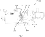
FIG. 1 shows a front structural schematic view of the power take-off transmission device provided by some implementations according to the present application. As shown inFIG. 1 , the power take-off transmission device 100 includes anelectric motor 110, ahydraulic pump 120 and amounting rack 130. Theelectric motor 110 includes an electricmotor output end 111. Thehydraulic pump 120 includes apump input end 121, and thehydraulic pump 120 may be an oil pump. Themounting rack 130 is provided between theelectric motor 110 and thehydraulic pump 120, and is configured to install theelectric motor 110 and thehydraulic pump 120. It can be understood that theelectric motor 110 and thehydraulic pump 120 are provided on themounting rack 130 together, which simplifies the structure. Themounting rack 130 is provided with amounting stop 1301 penetrating themounting rack 130 in an axial direction. The electricmotor output end 111 and thepump input end 121 are connected to each other via themounting stop 1301. The shape of the inner wall of themounting stop 1301 is adapted to the outer wall of the electricmotor output end 111 and/or the outer wall of thepump input end 121, so that themounting stop 1301 forms a radial limit to the electricmotor output end 111 and/or thepump input end 121, thereby ensuring that the electricmotor output end 111 and thepump input end 121 are coaxially installed in the axial direction X, which can avoid the occurrence of vibration, abnormal noise and oil leakage problems, thus guaranteeing the reliability of the power take-off transmission device. -
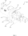
FIG. 3 shows a three-dimensional structural schematic view of the power take-off transmission device provided by the implementation shown inFIG. 1 . As shown inFIG. 3 , in a possible implementation, theelectric motor 110 further includes anelectric motor housing 113, and theelectric motor housing 113 is connected to themounting rack 130, thus making the installation structure of theelectric motor 110 more stable, further ensuring the coaxial installation of theelectric motor 110 and thehydraulic pump 120. -
FIG. 2 shows a partial three-dimensional structural schematic view of the power take-off transmission device provided by the implementation shown inFIG. 1 . As shown inFIG. 2 , in a possible implementation, themounting rack 130 is provided with a plurality ofcounterbore holes 1303 along a circumferential direction of themounting stop 1301 for respectively passing fasteners to connect themounting rack 130 and theelectric motor housing 113. Thecounterbore hole 1303 is a threaded hole, tencounterbore holes 1303 can be provided, tencounterbore holes 1303 are evenly provided around themounting stop 1301, and the recessed part of thecounterbore hole 1303 faces thehydraulic pump 120. The fastener is partially located in thecounterbore hole 1303, for example, the fastener can be a screw or a counterbore bolt, so that the installation structure of themounting rack 130 and theelectric motor 110 can be simplified. - As shown in
FIG. 3 , in a possible implementation, thehydraulic pump 120 further includes apump housing 123, and thepump housing 123 is connected to the mountingrack 130, thus making the installation structure of thehydraulic pump 120 more stable, and further ensuring the coaxial installation of thehydraulic pump 120 and theelectric motor 110. - As shown in
FIG. 3 , in a possible implementation, the mountingrack 130 is provided with a plurality of connectingholes 1305 along a circumferential direction of the mountingstop 1301, for example, four connectingholes 1305 is provided, and the connectinghole 1305 can be threaded hole or unthreaded hole, so as to respectively pass fasteners to connect the mountingrack 130 and thepump housing 123. Four connectingholes 1305 are provided around the mountingstop 1301, and the connectingholes 1305 can be provided on the same circumference as thecounterbore hole 1303, thus making the overall installation structure more compact. - As shown in
FIG. 1 , in a possible implementation, the electricmotor output end 111 and thepump input end 121 are inserted and matched in a concave and convex manner. When the electricmotor output end 111 is provided with a concave structure, such as a cylinder structure, the outer surface of the electricmotor output end 111 matches the inner surface of the mountingstop 1301 to further fix the electricmotor output end 111. For example, a convex structure can be provided on the outer surface of the electricmotor output end 111, a concave structure can be provided on the inner surface of the mountingstop 1301, and the convex structure is inserted into the concave structure to realize the purpose of further fixing the electricmotor output end 111. In this case, thepump input end 121 is provided with a convex structure, and the convex structure is inserted into the concave structure, so that it can be realized that the electricmotor output end 111 and thepump input end 121 are inserted and matched in a concave and convex manner, and the coaxial installation of the electricmotor output end 111 and thepump input end 121 can be better realized. - As shown in
FIG. 3 , in a possible implementation, the electricmotor output end 111 is a spline sleeve, and thepump input end 121 is a spline shaft and the spline sleeve is sleeved on an outside of the spline shaft. The spline sleeve is an internal spline, and the spline shaft is an external spline. Both the internal spline and the external spline are multi-tooth parts. The splines on the inner cylindrical surface are internal splines, and the splines on the outer cylindrical surface are external splines. The spline shaft and the spline sleeve cooperate to form a spline connection. Since more teeth and grooves are directly and evenly produced on the shaft and hub hole, the joint force is more uniform. Since the grooves are shallower, the stress concentration at the tooth root is smaller, the strength of the shaft and hub is less weakened. At the same time, due to the relatively large number of teeth and the relatively large total contact area, it can withstand relatively large loads. The parts on the shaft have good alignment with the shaft, and have good guidance quality. Therefore, the electricmotor output end 111 and thepump input end 121 have good transmission alignment and reliable transmission, which can reduce vibration, and avoid abnormal transmission noise and oil pump oil leakage problems. - As shown in
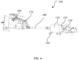
FIG. 3 , in a possible implementation, the power take-off transmission device 100 further includes anauxiliary rack 140 provided on a housing of an input end of theelectric motor 110.FIG. 4 shows a front structural schematic view of the power take-off transmission device provided by some implementations according to the present application. As shown inFIG. 4 , the power take-off transmission device 100 further includes aspeed transmission 160, apower takeoff 170 and a power take-off transmission shaft 180, and thepower takeoff 170 is connected to the output end of thespeed transmission 160. The output end of thepower takeoff 170 is connected to a universal joint, the output end of thepower takeoff 170 is connected to one end of the power take-off transmission shaft 180 by the universal joint, and another end of the power take-off transmission shaft 180 is connected to the input end of theelectric motor 110 by a universal joint. Therefore, the overall cantilever of the power take-off transmission device 100 is relatively long and is prone to vibration, thus leading to oil leakage problems. Theauxiliary rack 140 is L-shaped, and in order to increase the structural strength of theauxiliary rack 140, reinforcing ribs can be provided on theauxiliary rack 140. Theauxiliary rack 140 can be connected to theelectric motor housing 113 of theelectric motor 110 by fasteners, for example, the fastener can be a bolt. In addition, in order to ensure that theauxiliary rack 140 is adjustable, the mounting holes provided on theauxiliary rack 140 are long holes to ensure that the positions of theauxiliary rack 140 are adjustable in the front, back, left and right. Theauxiliary rack 140 is welded and fixed to the machine frame by a support board with adjustable upper and lower positions, and the support plate can be provided in the air. Theauxiliary rack 140 can solve the problem of the power take-off transmission device's cantilever being too long, thus increasing the system rigidity and reducing vibration. - The crane includes a machine frame and the power take-
off transmission device 100 in any implementation, and the power take-off transmission device 100 is provided on the machine frame. - The crane in the present application includes the power take-
off transmission device 100 in any of the above implementations, therefore, the crane has the technical effects of any of the above power take-off transmission device 100, which will not be described again here. - As shown in
FIG. 1 , the crane further includes asupport plate 200 fixedly connected to the machine frame. A mountingrack 130 of the power take-off transmission device 100 includes a mountingplate 131 and abottom plate 133, the mountingplate 131 is provided with a mountingstop 1301, the mountingplate 131 is connected to thebottom plate 133, and thebottom plate 133 is detachably connected to thesupport plate 200. In order to increase the overall structural strength of the mountingrack 130, arib plate 135 is provided on the plate surface of the side of the mountingplate 131 facing theelectric motor 110, and therib plate 135 is respectively connected to the mountingplate 131 and thebottom plate 133. The edge of thesupport plate 200 is provided with anarched part 210 to facilitate hoisting and ensure the convenience of hoisting and maintenance. Thesupport plate 200 is provided on the chassis plate of the vehicle frame. When the power take-off transmission device100 is hoisted, thebottom plate 133 and thesupport plate 200 can be detachably connected by bolts. - The basic principles of the present application have been described above in conjunction with specific embodiments. However, it should be noted that the advantages, benefit, effects, etc. mentioned in the present application are only examples and not limitations. It cannot be considered that these advantages, benefit, effects, etc. are necessarily possessed by each embodiment according to the present application. In addition, the specific details disclosed above are only for the purpose of illustration and to facilitate understanding, and are not limiting. The above details do not limit the application to be implemented using the above specific details.
- The components, devices, and equipment mentioned in the present application are only illustrative examples and are not intended to require or imply that they must be connected, provided, or configured in the manner shown in the block figures. As those skilled in the art will recognize, these components, devices, equipment, and systems may be connected, provided, or configured in any manner. Words such as "include" "contain" "have" etc. are open terms that mean "including, but not limited to," and may be used interchangeably therewith. As used herein, the words "or" and "and" refer to the words "and/or" and are used interchangeably therewith unless the context clearly dictates otherwise. As used herein, the word "such as" refers to the phrase "such as, but not limited to," and may be used interchangeably therewith.
- The above description of the disclosed aspects is provided to enable any person skilled in the art to make or use the present application. Various modifications to these aspects will be readily apparent to those skilled in the art, and the general principles defined herein may be applied to other aspects without departing from the scope of the application. Thus, the present application is not intended to be limited to the aspects shown herein but is to be accorded the widest scope consistent with the principles and novel features disclosed herein.
- The foregoing description has been presented for the purposes of illustration and description. Furthermore, this description is not intended to limit the embodiments according to the present application to the form disclosed herein. Although various example aspects and embodiments have been discussed above, those skilled in the art will recognize certain variations, modifications, changes, additions and sub-combinations thereof.
- The above are only some embodiments according to the present application and are not intended to limit the present application. Any modifications, equivalent substitutions, etc. made within the principles of the present application shall be included in the scope of the present application.
Claims (10)
- A power take-off transmission device, characterized by comprising:an electric motor comprising an electric motor output end;a hydraulic pump comprising a pump input end; anda mounting rack provided with a mounting stop penetrating the mounting rack in an axial direction; andwherein the electric motor output end and the pump input end are connected to each other via the mounting stop.
- The power take-off transmission device according to claim 1, wherein the electric motor further comprises an electric motor housing, and the electric motor housing is connected to the mounting rack.
- The power take-off transmission device according to claim 2, wherein the mounting rack is provided with a plurality of counterbore holes along a circumferential direction of the mounting stop for respectively passing fasteners to connect the mounting rack and the electric motor housing.
- The power take-off transmission device according to claim 1, wherein the hydraulic pump further comprises a pump housing, and the pump housing is connected to the mounting rack.
- The power take-off transmission device according to claim 4, wherein the mounting rack is provided with a plurality of connecting holes along a circumferential direction of the mounting stop for respectively passing fasteners to connect the mounting rack and the pump housing.
- The power take-off transmission device according to any one of claims 1 to 5, wherein the electric motor output end and the pump input end are inserted and matched in a concave and convex manner.
- The power take-off transmission device according to claim 6, wherein the electric motor output end is a spline sleeve, the pump input end is a spline shaft, and the spline sleeve is sleeved on an outside of the spline shaft.
- The power take-off transmission device according to any one of claims 1 to 5, further comprising:
an auxiliary rack provided at an input end of the electric motor housing of the electric motor. - A crane, characterized by comprising:a machine frame;the power take-off transmission device according to any one of claims 1 to 8, wherein the power take-off transmission device is provided on the machine frame.
- The crane according to claim 9, further comprising:a support plate fixedly connected to the machine frame;wherein a mounting rack of the power take-off transmission device comprises a mounting plate and a bottom plate, the mounting plate is provided with a mounting stop, the mounting plate is connected to the bottom plate, and the bottom plate is detachably connected to the support plate.
Applications Claiming Priority (2)
| Application Number | Priority Date | Filing Date | Title |
|---|---|---|---|
| CN202122101569.5U CN215805832U (en) | 2021-09-01 | 2021-09-01 | Power take-off transmission device and crane |
| PCT/CN2022/073804 WO2023029368A1 (en) | 2021-09-01 | 2022-01-25 | Power take-off transmission device and crane |
Publications (3)
| Publication Number | Publication Date |
|---|---|
| EP4389488A1 true EP4389488A1 (en) | 2024-06-26 |
| EP4389488A4 EP4389488A4 (en) | 2025-07-16 |
| EP4389488B1 EP4389488B1 (en) | 2026-04-29 |
Family
ID=80154812
Family Applications (1)
| Application Number | Title | Priority Date | Filing Date |
|---|---|---|---|
| EP22862519.0A Active EP4389488B1 (en) | 2021-09-01 | 2022-01-25 | Power take-off transmission device and crane |
Country Status (3)
| Country | Link |
|---|---|
| EP (1) | EP4389488B1 (en) |
| CN (1) | CN215805832U (en) |
| WO (1) | WO2023029368A1 (en) |
Family Cites Families (8)
| Publication number | Priority date | Publication date | Assignee | Title |
|---|---|---|---|---|
| DE2745628C3 (en) * | 1977-10-11 | 1980-04-24 | Jean Walterscheid Gmbh, 5204 Lohmar | Device for coupling and uncoupling a cardan shaft |
| ITMI20010436A1 (en) * | 2001-03-02 | 2002-09-02 | Comer Group S P A | REDUCER GROUP PARTICULARLY FOR THE OPERATION OF THE AUGERS OF MIXING WAGONS AND AUXILIARY ELEMENTS |
| CN2564778Y (en) * | 2002-04-29 | 2003-08-06 | 烟台电机有限公司 | Unit construction gear oil pump motor |
| JP4680769B2 (en) * | 2005-12-28 | 2011-05-11 | 富士重工業株式会社 | Hybrid drive device for work vehicle |
| CN201931993U (en) * | 2010-12-28 | 2011-08-17 | 徐州重型机械有限公司 | Crane and mechanism drive device |
| CN202439566U (en) * | 2012-02-09 | 2012-09-19 | 北京机械设备研究所 | Power-takeoff transmission device for special automobile hydraulic system |
| CN211335580U (en) * | 2020-01-06 | 2020-08-25 | 湖北航天技术研究院特种车辆技术中心 | Tandem type multi-output power takeoff device |
| CN212803973U (en) * | 2020-07-31 | 2021-03-26 | 湖南铂诚数字科技有限公司 | Direct connection structure for motor and hydraulic pump of electric stacker |
-
2021
- 2021-09-01 CN CN202122101569.5U patent/CN215805832U/en active Active
-
2022
- 2022-01-25 WO PCT/CN2022/073804 patent/WO2023029368A1/en not_active Ceased
- 2022-01-25 EP EP22862519.0A patent/EP4389488B1/en active Active
Also Published As
| Publication number | Publication date |
|---|---|
| WO2023029368A1 (en) | 2023-03-09 |
| EP4389488B1 (en) | 2026-04-29 |
| CN215805832U (en) | 2022-02-11 |
| EP4389488A4 (en) | 2025-07-16 |
Similar Documents
| Publication | Publication Date | Title |
|---|---|---|
| EP4389488A1 (en) | Power take-off transmission device and crane | |
| CN205715320U (en) | The attachment structure of compressor crank shaft and line shaft and extracting tool thereof | |
| CN110701286A (en) | Power head speed reducer and pile machine | |
| CN217898659U (en) | Idler shaft supporting structure | |
| CN106704492B (en) | Modularized yaw pitch drive device | |
| CN211915529U (en) | High-rigidity high-precision numerical control machine tool spindle connecting structure | |
| CN212305011U (en) | Synchronous gang double-shaft drive output speed reducing motor | |
| CN108944394A (en) | Electric car and its integrated dynamic assembly | |
| EP3477826A1 (en) | Transmission device and air-cooling island | |
| CN208730779U (en) | Electric car and its integrated dynamic assembly | |
| CN222974830U (en) | Mounting and fixing structure for auxiliary portal rotary input shaft of ascending three-way stacker | |
| CN201696527U (en) | Variable speed clutch | |
| CN209725108U (en) | A kind of multistage speed reducer | |
| CN106763264B (en) | Metal disc-folding flexible coupling | |
| CN219013156U (en) | Coaxial 48V P1 mixed motion special transmission shaft | |
| CN223524376U (en) | Parallel transmission case | |
| CN219570400U (en) | Diesel engine and oil pump connection structure | |
| CN201196259Y (en) | Fork truck speed reducer of accumulator | |
| CN223424584U (en) | Reducer and crane | |
| CN223213636U (en) | Split type tool ring for hoisting engine | |
| CN218093687U (en) | Fixing and output device of cycloid motor | |
| CN218206854U (en) | Novel transmission connecting device | |
| CN218674241U (en) | Gearbox rack testing device | |
| CN223257333U (en) | Flywheel coupling of engine | |
| CN223549756U (en) | A high-speed connecting shaft assembly, transmission and automobile |
Legal Events
| Date | Code | Title | Description |
|---|---|---|---|
| STAA | Information on the status of an ep patent application or granted ep patent |
Free format text: STATUS: THE INTERNATIONAL PUBLICATION HAS BEEN MADE |
|
| PUAI | Public reference made under article 153(3) epc to a published international application that has entered the european phase |
Free format text: ORIGINAL CODE: 0009012 |
|
| STAA | Information on the status of an ep patent application or granted ep patent |
Free format text: STATUS: REQUEST FOR EXAMINATION WAS MADE |
|
| 17P | Request for examination filed |
Effective date: 20240322 |
|
| AK | Designated contracting states |
Kind code of ref document: A1 Designated state(s): AL AT BE BG CH CY CZ DE DK EE ES FI FR GB GR HR HU IE IS IT LI LT LU LV MC MK MT NL NO PL PT RO RS SE SI SK SM TR |
|
| DAV | Request for validation of the european patent (deleted) | ||
| DAX | Request for extension of the european patent (deleted) | ||
| A4 | Supplementary search report drawn up and despatched |
Effective date: 20250617 |
|
| RIC1 | Information provided on ipc code assigned before grant |
Ipc: B60K 25/06 20060101AFI20250611BHEP Ipc: B66C 13/18 20060101ALI20250611BHEP Ipc: F16D 1/04 20060101ALI20250611BHEP |
|
| GRAP | Despatch of communication of intention to grant a patent |
Free format text: ORIGINAL CODE: EPIDOSNIGR1 |
|
| STAA | Information on the status of an ep patent application or granted ep patent |
Free format text: STATUS: GRANT OF PATENT IS INTENDED |
|
| GRAS | Grant fee paid |
Free format text: ORIGINAL CODE: EPIDOSNIGR3 |
|
| GRAA | (expected) grant |
Free format text: ORIGINAL CODE: 0009210 |
|
| STAA | Information on the status of an ep patent application or granted ep patent |
Free format text: STATUS: THE PATENT HAS BEEN GRANTED |
|
| INTG | Intention to grant announced |
Effective date: 20260304 |
|
| AK | Designated contracting states |
Kind code of ref document: B1 Designated state(s): AL AT BE BG CH CY CZ DE DK EE ES FI FR GB GR HR HU IE IS IT LI LT LU LV MC MK MT NL NO PL PT RO RS SE SI SK SM TR |
|
| REG | Reference to a national code |
Ref country code: CH Ref legal event code: F10 Free format text: ST27 STATUS EVENT CODE: U-0-0-F10-F00 (AS PROVIDED BY THE NATIONAL OFFICE) Effective date: 20260429 |