EP4389473A1 - Dispositif de fixation d'une extrémité d'une barre anti-dévers à un système de suspension d'un véhicule, et véhicule associé - Google Patents
Dispositif de fixation d'une extrémité d'une barre anti-dévers à un système de suspension d'un véhicule, et véhicule associé Download PDFInfo
- Publication number
- EP4389473A1 EP4389473A1 EP23218724.5A EP23218724A EP4389473A1 EP 4389473 A1 EP4389473 A1 EP 4389473A1 EP 23218724 A EP23218724 A EP 23218724A EP 4389473 A1 EP4389473 A1 EP 4389473A1
- Authority
- EP
- European Patent Office
- Prior art keywords
- roll bar
- fixing
- fraction
- cylindrical body
- vehicle
- Prior art date
- Legal status (The legal status is an assumption and is not a legal conclusion. Google has not performed a legal analysis and makes no representation as to the accuracy of the status listed.)
- Pending
Links
- 239000000725 suspension Substances 0.000 title claims abstract description 42
- 230000000284 resting effect Effects 0.000 claims abstract description 5
- 230000004323 axial length Effects 0.000 claims description 35
- 238000010079 rubber tapping Methods 0.000 claims description 22
- 230000001681 protective effect Effects 0.000 claims description 10
- 238000003466 welding Methods 0.000 description 9
- 239000002184 metal Substances 0.000 description 5
- 230000036961 partial effect Effects 0.000 description 5
- 229910000831 Steel Inorganic materials 0.000 description 3
- 238000004519 manufacturing process Methods 0.000 description 3
- 239000000463 material Substances 0.000 description 3
- 230000002829 reductive effect Effects 0.000 description 3
- 239000010959 steel Substances 0.000 description 3
- 101150004367 Il4i1 gene Proteins 0.000 description 2
- 238000002788 crimping Methods 0.000 description 2
- 239000000428 dust Substances 0.000 description 2
- 238000010438 heat treatment Methods 0.000 description 2
- 238000003780 insertion Methods 0.000 description 2
- 230000037431 insertion Effects 0.000 description 2
- 239000007788 liquid Substances 0.000 description 2
- 239000004576 sand Substances 0.000 description 2
- 239000004593 Epoxy Substances 0.000 description 1
- 230000005540 biological transmission Effects 0.000 description 1
- 239000011248 coating agent Substances 0.000 description 1
- 238000000576 coating method Methods 0.000 description 1
- 238000005242 forging Methods 0.000 description 1
- 230000012010 growth Effects 0.000 description 1
- 230000000670 limiting effect Effects 0.000 description 1
- 230000007257 malfunction Effects 0.000 description 1
- 238000000034 method Methods 0.000 description 1
- 238000011084 recovery Methods 0.000 description 1
- 230000006641 stabilisation Effects 0.000 description 1
- 238000011105 stabilization Methods 0.000 description 1
- 239000003381 stabilizer Substances 0.000 description 1
- 239000000126 substance Substances 0.000 description 1
Images


Classifications
-
- B—PERFORMING OPERATIONS; TRANSPORTING
- B60—VEHICLES IN GENERAL
- B60G—VEHICLE SUSPENSION ARRANGEMENTS
- B60G21/00—Interconnection systems for two or more resiliently-suspended wheels, e.g. for stabilising a vehicle body with respect to acceleration, deceleration or centrifugal forces
- B60G21/02—Interconnection systems for two or more resiliently-suspended wheels, e.g. for stabilising a vehicle body with respect to acceleration, deceleration or centrifugal forces permanently interconnected
- B60G21/04—Interconnection systems for two or more resiliently-suspended wheels, e.g. for stabilising a vehicle body with respect to acceleration, deceleration or centrifugal forces permanently interconnected mechanically
- B60G21/05—Interconnection systems for two or more resiliently-suspended wheels, e.g. for stabilising a vehicle body with respect to acceleration, deceleration or centrifugal forces permanently interconnected mechanically between wheels on the same axle but on different sides of the vehicle, i.e. the left and right wheel suspensions being interconnected
- B60G21/055—Stabiliser bars
-
- F—MECHANICAL ENGINEERING; LIGHTING; HEATING; WEAPONS; BLASTING
- F16—ENGINEERING ELEMENTS AND UNITS; GENERAL MEASURES FOR PRODUCING AND MAINTAINING EFFECTIVE FUNCTIONING OF MACHINES OR INSTALLATIONS; THERMAL INSULATION IN GENERAL
- F16C—SHAFTS; FLEXIBLE SHAFTS; ELEMENTS OR CRANKSHAFT MECHANISMS; ROTARY BODIES OTHER THAN GEARING ELEMENTS; BEARINGS
- F16C11/00—Pivots; Pivotal connections
- F16C11/04—Pivotal connections
- F16C11/06—Ball-joints; Other joints having more than one degree of angular freedom, i.e. universal joints
- F16C11/0695—Mounting of ball-joints, e.g. fixing them to a connecting rod
-
- B—PERFORMING OPERATIONS; TRANSPORTING
- B60—VEHICLES IN GENERAL
- B60G—VEHICLE SUSPENSION ARRANGEMENTS
- B60G2204/00—Indexing codes related to suspensions per se or to auxiliary parts
- B60G2204/10—Mounting of suspension elements
- B60G2204/12—Mounting of springs or dampers
- B60G2204/122—Mounting of torsion springs
- B60G2204/1224—End mounts of stabiliser on wheel suspension
-
- B—PERFORMING OPERATIONS; TRANSPORTING
- B60—VEHICLES IN GENERAL
- B60G—VEHICLE SUSPENSION ARRANGEMENTS
- B60G2204/00—Indexing codes related to suspensions per se or to auxiliary parts
- B60G2204/40—Auxiliary suspension parts; Adjustment of suspensions
- B60G2204/416—Ball or spherical joints
-
- B—PERFORMING OPERATIONS; TRANSPORTING
- B60—VEHICLES IN GENERAL
- B60G—VEHICLE SUSPENSION ARRANGEMENTS
- B60G2206/00—Indexing codes related to the manufacturing of suspensions: constructional features, the materials used, procedures or tools
- B60G2206/01—Constructional features of suspension elements, e.g. arms, dampers, springs
- B60G2206/40—Constructional features of dampers and/or springs
- B60G2206/42—Springs
- B60G2206/427—Stabiliser bars or tubes
Definitions
- the invention relates, in general, to any system comprising a ball joint pivot to be joined together, and in particular to such a system operating in a vibratory environment and subject to significant and repeated alternating stresses.
- the invention relates more specifically to an anti-roll bar for a motor vehicle, and relates more particularly to a device for fixing the ends of the anti-roll bar to a vehicle suspension system.
- anti-roll bar also called an anti-roll bar or stabilizer bar, which consists of a metal part, for example steel, substantially U-shaped. circular section and which limits the inclination of the vehicle in curves or in potholes.
- an anti-roll bar connects at each of its ends one of the two suspension systems of the same set of wheels of the vehicle. Each end of the anti-roll bar is therefore linked to the suspension system of one of the wheels of the same set of wheels using a fixing device.
- this fixing device is formed by a screw connection. More specifically, the end of the anti-roll bar is heated and forged to be crushed, bent and then drilled to accommodate a screw and a nut. A link is connected by a first end to the suspension system intended to be connected to said end of the anti-roll bar. The opposite end of this link is secured via the screw and the nut to said end of the anti-roll bar.
- FIG. 1 a partial perspective view of a motor vehicle 1 equipped with an anti-roll assembly 2 according to the prior art.
- the anti-roll assembly 2 includes an anti-roll bar 3, also called an anti-roll bar or stabilization bar.
- the anti-roll bar 3 is, in known manner, a metal part, for example made of steel, substantially U-shaped and of circular section.
- the anti-roll bar 3 thus comprises two identical side arms 3a, and a central section 3b connecting the two side arms 3a via one of their ends.
- Each of the lateral arms 3a thus comprises an end linked to the central section 3b and an opposite free end.
- the anti-roll bar 3 is fixed to the chassis of the vehicle 1 by bearings 1a and 1b partially enclosing the central section 3b.
- vehicle 1 For the same set of front or rear wheels of vehicle 1, vehicle 1 comprises a suspension system 4 associated with each of the wheels.
- the vehicle 1 therefore includes a suspension system 4 for the left wheel and a suspension system 4 for the right wheel.
- Each suspension system 4 is connected to the anti-roll assembly 2 via an identical fixing device 5.
- the fixing device 5 comprises a link 6 and a means 7 for fixing the link to the anti-roll bar 3.
- the link 6 is a metal rod having a first end formed by a first ball joint 7a and a second opposite end formed by a second ball joint 7b.
- the first ball joint 7a connects the link 6 to the anti-roll assembly 2, and more precisely to the anti-roll bar 3, while the second ball joint 7b connects the link 6 to the suspension system 4.
- the ball joints 7a and 7b allow thus to the link 6 in a known manner to orient itself according to the relative movement of the suspension system 4 relative to the anti-roll bar 3.
- the fixing means 7 comprises a fixing insert 8 and a connecting member 9 of the link to the fixing insert illustrated in partial longitudinal section on the figure 2 .
- the fixing insert 8 comprises a support head 8a and a cylindrical body 8b of substantially circular section and of constant diameter less than the diameter of the circular section of the anti-roll bar 3.
- the support head 8a constitutes the one of the ends of the cylindrical body 8b and forms a collar of diameter greater than the diameter respectively of the cylindrical body 8b and of the circular section of the anti-roll bar 3.
- a longitudinal section of the fixing insert is therefore substantially in the shape of " T”.
- the fixing insert 8 is thus partially introduced into one end of the anti-roll bar 3. More precisely, the introduction of the fixing insert 8 into the end of the anti-roll bar 3 is done by insertion of the cylindrical body 8b into the bar 3.
- the support head 8a blocks the introduction of the insert 8 into the bar 3, and rests against the entrance to the end of the anti-roll bar 3. In other words, the support head 8a is positioned against the end of the anti-roll bar and in its axial extension.
- the fixing insert 8 and the end of the anti-roll bar 3 extend along the same axis A carrying the center of their respective circular sections.
- the diameter of the cylindrical body 8b is sufficiently smaller than the diameter of the anti-roll bar 3 so that no contact takes place between the cylindrical body 8b and the anti-roll bar 3.
- the cylindrical body 8b therefore comprises an external surface 10 facing the internal walls of the end of the anti-roll bar 3. This external surface 10 defines an external part 10 of the fixing insert 8.
- the insert 8 is fixed to the anti-roll bar 3 by an electric resistance weld 8c at the level of the contact between the support head 8a of the insert 8 and the end of the anti-roll bar 3 , as shown in the figure 2 .
- the fixing insert 8 is blind.
- a cylindrical cavity 8d is made in the insert 8, this cylindrical cavity 8d passing through the insert 8 and opening out at the support head 8a on the outside of the insert 8.
- the cavity 8d is on the other hand closed on its end opposite the support head 8a.
- the cavity 8d therefore constitutes a housing whose access is constituted by the part opening onto the support head 8a.
- the cavity 8d is cylindrical and is defined by internal walls 11 of the insert 8 of circular section and whose center is carried by the axis A.
- the fixing insert 8 therefore comprises an internal part 11 defined by the walls 11 of the cavity 8c, and an external part 10 defined by the external surface 10 of the cylindrical body 8b.
- the connecting member 9 is fixed to the first ball joint 7a of the link 6, and comprises a protective bellows 12, a tightening means 13 and a threaded end piece 14 aligned along the axis A, so that the connecting member connection 9 extends the same axis A as the cavity 8d, the fixing insert 8 and the end of the anti-roll bar 3.
- the clamping means 13 comprises for example a hexagonal crown intended to serve as a grip for a tightening tool such as an adjustable wrench.
- the protective bellows 12 is arranged in a known manner around a thread of material 12a illustrated in dotted lines on the figure 2 and connecting the clamping means 13 to ball joint 7a. In this way, the bellows 12 protects the ball joint 7a from impact with the tightening tool when tightening the connecting member 9, and also protects the ball joint 7a from possible external attacks such as liquids, sand or dust.
- the threaded end piece 14 extends from a surface of the clamping means 13 opposite the ball joint 7a and the protective bellows 12.
- the radial dimension of the clamping means 13 is greater than the diameter of the threaded end 14, so that the use of the clamping tool is facilitated and the risk of damage reduced.
- the internal surface forming the internal part 11 of the fixing insert 8 is threaded so that the threaded end piece 14 is configured to insert into the internal part of the insert 8 and cooperate with said thread.
- the connecting member 9 is therefore configured to cooperate with the internal part 11 to secure the insert 8 to the ball joint 7a.
- the axial length of the threaded end piece 14 is substantially equal to the axial length of the internal part 11 of the fixing insert 8.
- the clamping means 13 comprises a surface at contact of the head 8a of the insert 8.
- the ball joint 7a of the link 6 is fixed to the anti-roll assembly 2, and more particularly to the anti-roll bar 3 via the connecting member 9 partially inserted in the fixing insert 8 which is secured in a free and hollow end of a lateral arm 3a of the anti-roll bar 3.
- the attachment of the insert 8 to the anti-roll bar 3 is done solely by welding, so that it is the welding which takes up all the forces and moments transmitted by the suspension system 4 and the wheel corresponding to the anti-roll assembly 2. These forces and moments result from alternating hinge-type stresses, which can cause breakage of the weld or even the fixing insert 8 and/or the thread/tapping assembly.
- the threading/tapping system between the connecting member 9 and the internal part 10 of the fixing insert 8 is not sufficiently robust with regard to the stresses suffered, which can cause wear and unscrewing due to their alternation.
- the tapping being very close to the welding zone, the heating necessary for welding can cause changes in the mechanical characteristics of the tapping, resulting in a malfunction of the assembly.
- the present invention therefore aims to avoid the aforementioned drawbacks and to propose a device for fixing one end of an anti-roll bar from a vehicle to a vehicle suspension system that is easy to manufacture, inexpensive and robust.
- the subject of the invention is therefore a device for fixing one end of an anti-roll bar of a vehicle to a vehicle suspension system, comprising a link intended to be connected to the suspension system and a fixing means from the link to the anti-roll bar, the link comprising one end equipped with a ball joint, the fixing means comprising a connecting member fixed to the ball joint and a fixing insert comprising a cylindrical body extending along an axis and a support head formed on one end of the cylindrical body, the support head resting against the end of the anti-roll bar and the body being inserted into the end of the anti-roll bar, the fixing insert comprising an internal part opening onto the support head and receiving a rod of the connecting member, the cylindrical body comprising an external part facing the interior of the anti-roll bar.
- the sum of the axial lengths of the at least one radial protrusion is less than half of the total axial length of the cylindrical body.
- the internal part comprises a first portion of diameter D1 and of axial length L1, a second portion of diameter D2 and of axial length L2, and a third portion of diameter D3 and of axial length L3, the second portion being axially positioned between the first portion and the third portion, the first portion comprising the opening opening from the internal part onto the support head, the diameters of the three portions being linked by the relationship: D3 ⁇ D2 ⁇ D1
- the first portion and the second portion are smooth, and the third portion is partially tapped, the tapping being arranged in axial contact with the second portion.
- the rod of the connecting member comprises a first fraction of diameter D4 and length L4 and a second fraction of diameter D5 and length L5, the first fraction being arranged between the support head and the second fraction , the diameters of the two portions being linked by the relation: D 5 ⁇ D 4
- the first fraction is smooth, the second portion being fitted onto the first fraction, the second fraction being threaded and cooperating with the tapping of the third portion of the fixing insert.
- the respective axial lengths L5 and L2 of the second fraction and the second portions are connected by the following relationship L 2 ⁇ L 5
- the connecting member comprises a tightening means which can be activated using a tightening tool, the connecting member further comprising a first and a second protective base arranged on either side axially and in contact with the clamping means, the first base being arranged axially in contact and between the rod and the clamping means.
- the axial length L4 of the first fraction and the respective axial lengths L1 and L2 of the first and second portions are connected by the following relationship: L 4 ⁇ L 1 + L 2
- the invention also relates to a vehicle comprising a set of wheels comprising a first and a second wheel, the first wheel being associated with a first suspension system and the second wheel being associated with a second suspension system, the two systems of suspension being connected together via an anti-roll bar of the vehicle, the anti-roll bar being fixed to the suspension systems by each of its ends by means of a fixing device as defined above.
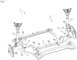
- FIG. 3 a partial perspective view of a motor vehicle 15 equipped with an anti-roll assembly 16 according to the invention.
- the anti-roll assembly 16 comprises a metal anti-roll bar 17, for example made of steel, substantially U-shaped and of circular section.
- the anti-roll bar 17 thus comprises two identical lateral arms 17a, and a central section 17b connecting the two lateral arms 17a via one of their ends.
- Each of the lateral arms 17a thus comprises an end linked to the central section 17b and an opposite hollow free end 17c, this free end 17c corresponding to one end of the anti-roll bar 17.
- Each of the opposite free ends 17c extends up to a slice 17d formed by a lateral surface and comprising an entrance giving access to the interior of the free end, this interior being formed by an internal wall 17e.
- the anti-roll bar 17 is fixed to the vehicle chassis 15 by bearings 15a and 15b partially enclosing the central section 17b.
- the vehicle 15 comprises a suspension system 18 of the same set of front or rear wheels of the vehicle 15 associated with each of the wheels.
- the vehicle 15 therefore comprises a suspension system 18 for the left wheel and a suspension system 18 for the right wheel.
- Each suspension system 18 is connected to the anti-roll assembly 16 via a fixing device 19. More precisely, the fixing devices 19 each allow a suspension system 18 to be connected to a hollow end 17c d a lateral arm 17a of the anti-roll bar 17.
- fixing devices 19 for example the fixing device 19 of the left wheel, all of which will be described being symmetrical and identical for the right side.
- a fixing device 19 is illustrated in partial longitudinal section on the Figure 4 .
- the left hollow free end 17c of the anti-roll bar 17 is thus illustrated on the Figure 4 and extends along a longitudinal axis B.
- the lateral surface forming the end edge 17d is thus orthogonal to the axis B.
- the fixing device 19 comprises a link 20 and a means 21 for fixing the link to the anti-roll bar 17. More precisely, the fixing means 21 is a means for fixing the link 20 to the hollow end 17c d a lateral arm 17a of the anti-roll bar 17.
- the link 20 is a metal rod having a first end formed by a first ball joint 21a and a second opposite end formed by a second ball joint 21b.
- the first ball joint 21a connects the link 20 to the anti-roll bar 17, and more precisely to the hollow end 17c of a lateral arm 17a of the anti-roll bar 17, while the second ball joint 21b connects the link 20 to the suspension system 18.
- the ball joints 21a and 21b thus allow the link 20 to orient itself according to the relative movement of the suspension system 18 relative to the anti-roll bar 17.
- the fixing means 21 comprises a fixing insert 22 and a connecting member 23 of the link to the fixing insert illustrated in partial longitudinal section on the Figure 4 .
- the fixing insert 22 comprises a support head 22a and a cylindrical body 22b of substantially circular section and of diameter less than or equal to the diameter of the circular section of the anti-roll bar 17 defined between the opposite interior walls 17e of a plane orthogonal to the axis B of the anti-roll bar 17.
- the support head 22a constitutes one of the ends of the cylindrical body 22b and forms a collar of diameter greater than the diameter respectively of the cylindrical body 22b and of the section circular of the anti-roll bar 17.
- a longitudinal section of the fixing insert 22 therefore has substantially a “T” shape.
- the fixing insert 22 is thus partially introduced into the hollow end 17c of a lateral arm 17a of the anti-roll bar 17. More precisely, the introduction of the fixing insert 22 into the end 17c of the anti-roll bar 17 is done by inserting the cylindrical body 22b into the bar 17 via the end edge 17d.
- the support head 22a blocks the introduction of the insert 22 into the bar 17, and rests against the edge 17d of the end 17c of the anti-roll bar 17. In other words, the head d
- the support 22a is positioned against the edge 17d of the end 17c of the anti-roll bar 17 and in its axial extension.
- the fixing insert 22 and the hollow end 17c of the lateral arm 17b of the anti-roll bar 17 extend along the same axis B carrying the center of their respective circular section.
- the cylindrical body 22b therefore comprises an external surface 24 facing the internal wall 17e of the end 17c of the anti-roll bar 17. This external surface 24 defines an external part 24 of the fixing insert 22.
- the insert 22 is fixed to the anti-roll bar 17 by an electric resistance weld 22c at the level of the contact between the support head 22a of the insert 22 and the edge 17d of the end 17c of the anti-roll bar 17, as shown in the Figure 4 .
- the welding is therefore carried out at points located on a surface of the support head 22a facing the end 17c of the anti-roll bar 3, and on the edge 17d of the end 17c.
- the external part 24 therefore has a circular section of diameter less than the diameter of the circular section of the anti-roll bar 17 defined by the internal wall 17e.
- the external part 24 further comprises at least one radial protrusion 25.
- the at least one radial protrusion 25 is preferably annular, and extends radially sufficiently to establish contact with the interior wall 17e of the anti-roll bar 17.
- the at least one radial protrusion 25 therefore punctually gives in its axial position to the cylindrical body 22b a circular section of diameter equal to the diameter of the interior wall 17e of the anti-roll bar 17.
- the at least one radial projection 25 of the cylindrical body 22b constitutes for the fixing insert 22 at least one additional point of support on the anti-roll bar 17, in addition to the weld.
- the forces and moments undergone by the anti-roll bar 17 and transmitted by the wheels and the suspension systems 18 are no longer fully taken up by the weld 22c, but also by the points of the bar 17 in contact with the at least one radial protrusion 25.
- the weld 22c is therefore preserved, and the fixing device 19 gains in robustness.
- the at least one protrusion 25 is preferably positioned on the side of the external part 24 opposite the support head 22a in order to optimize the effectiveness of the lever arm.
- the example illustrated on the Figure 4 comprises a first protrusion 25a and a second protrusion 25b, the first protrusion 25a being arranged opposite the support head 22a, and the second protrusion 25b being arranged between the first protrusion 25a and the support head 22a.
- the sum of the axial lengths of at least one radial protrusions 25 is less than half of the total length of the cylindrical body 22a.
- the fixing insert 22 is lightened, the forces necessary for the insertion of the fixing insert 22 into the anti-roll bar 17 are reduced while guaranteeing improved robustness.
- the at least one protrusion 25 that is to say in the example illustrated the protrusions 25a and 25b, also make it possible to ensure better centering of the fixing insert 22 in the end 17c of the anti-roll bar 17, so as to guarantee the coaxial nature along axis B of the elements of the fixing device 19 according to the invention. In this way, the centering of the first ball joint 21a is improved.
- the fixing insert 22 is blind.
- a cylindrical cavity 22d is made in the insert 22, this cylindrical cavity 22d passing through the insert 22 and opening out at the level of the support head 22a on the exterior of the insert 22.
- the cavity 22d is, however, closed on its end opposite the support head 22a.
- the cavity 22d therefore constitutes a housing whose access is constituted by a part opening onto the support head 22a.
- the cavity 22d is cylindrical and is defined by an internal wall 26 of the insert 22 of circular section and whose center is carried by the axis B.
- the fixing insert 22 therefore comprises an internal part 26 defined by the internal wall 26 of the cavity 22d, and an external part 24 defined by the external surface 24 of the cylindrical body 22b.
- the internal part 26 comprises a first portion 26a of diameter D1 and of axial length L1 along the axis B, a second portion 26b of diameter D2 and of axial length L2 along the axis B and a third portion 26c of diameter D3 and axial length L3 along axis B.
- the first portion 26a extends axially between the opening part of the cavity 22d on the support head 22a and the second portion 26b, located at an axial length L1 from the opening part of the cavity 22d.
- the third portion 26c extends from the closed end of the cavity 22d to the second portion 26b, located at an axial length L3 from said closed end of the cavity 22d.
- the second portion 26b is axially positioned and extends axially between the first portion 26a and the third portion 26b.
- the first and second portions 26a and 26b have smooth walls, while the third portion 26c is partially tapped.
- the third portion 26c comprises a tapping extending axially from the second portion 26b to a point axially distant from the second portion 26b of a length less than L3, the remaining part of the third portion 26c comprising smooth walls.
- the connecting member 23 is fixed to the first ball joint 21a of the link 20, and comprises a protective bellows 27, a clamping means 28 and a rod 29 aligned along the axis B, so that the connecting member 23 extends the same axis B as the cavity 22d, the fixing insert 22 and the end 17c of the anti-roll bar 17.
- the clamping means 28 comprises for example a hexagonal crown intended to serve as a grip for a tightening tool such as an adjustable wrench.
- the protective bellows 27 is arranged in a known manner around a thread of material 27a illustrated in dotted lines on the Figure 4 connecting the clamping means 28 to the first ball joint 21a. In this way, the bellows 27 protects the ball joint 21a from impact with the tightening tool when tightening the connecting member 23, and also protects the ball joint 21a from possible external attacks such as liquids, sand or dust.
- the connecting member 23 further comprises a first base 30 and a second base 31 aligned along the axis B with the rod 29, the clamping means 28, and the protective bellows 27 associated with the thread of material 27a.
- the first base 30 is arranged axially between and in contact with the clamping means 28 and the rod 29.
- the second base 31 is arranged axially between and in contact with the clamping means 28 and the protective bellows 27.
- the first base 30 comprises a surface 30a orthogonal to the flat axis B resting against the support head 22a, this surface 30a participating in the transmission of the forces and moments coming from the suspension system 18 to the insert 22.
- the second base 31 is symmetrical and identical to the first base with respect to the clamping means 28, the second base 31 comprising a surface 31a orthogonal to the plane axis B in contact with the protective bellows 27.
- the bases 30 and 31 have a radial dimension greater than the diameter of the clamping means 28, and thus make it possible to protect the elements of the fixing device 19 when using the tightening tool on the clamping means 28.
- the first base 30 protects a coating of the anti-roll bar 17 constituted by an organic protection against chemical and/or mechanical attacks coming from the external environment, such as an epoxy protection.
- the rod 29 extends from the surface 30a of the first base 30, the first base 30a resting against the support head 22a.
- the rod 29 has a circular section orthogonal to the axis B.
- the rod 29 comprises a first fraction 29a of diameter D4 and of axial length L4 along the axis B, and a second fraction 29b of diameter D5 and of axial length L5 according to axis B.
- the first fraction 29a is arranged axially between the clamping means 28 and the second fraction 29b, and more precisely between the first base 30 and the second fraction 29b, the second fraction 29b forming the end of the connecting member 23 opposite to the support head 22a.
- the first fraction 29a is smooth while the second fraction 29b is threaded.
- the rod 29 is configured to insert into the internal part 26 of the insert 22 and cooperate with the fixing insert 22. More precisely, the diameter D5 of the second fraction 29b is substantially equal to the diameter D3 of the third portion 26c. In addition, the threading of the second fraction 29b is able to cooperate with the tapping of the third portion 26c. Thus, the second fraction 29b is configured to cooperate with the third portion 26c for securing the fixing insert 22 with the connecting member 23.
- the axial length of the tapping of the third portion 26c is less than the axial length L3 of this third portion 26c, so that the third portion 26c comprises a smooth axial part.
- the diameter D4 of the first fraction 29a is substantially equal to the diameter D2 of the second portion 26b, greater than the diameter D3, and less than the diameter D1 of the first portion 26a.
- the second portion 26b is configured to be fitted onto the first fraction 29a during the introduction of the rod 29 into the cavity 26 of the fixing insert 22.
- the securing of the fixing insert 22 to the connecting member 23 is therefore done on the one hand by shrinking the second portion 26b onto a part of the first fraction 29a and on the other hand by cooperation of the respective threading and tapping of the second fraction 29b and the third portion 26c.
- the support of the first base 30 on the support head 22a also constitutes a final means of securing the insert 22 to the connecting member 23, making it possible to relieve the threading/tapping.
- the axial length of the rod 29, equal to the sum of the axial length L4 of the first fraction and the axial length L5 of the second threaded fraction 29b, is less than the axial length between the end of the head support 22a in contact with the first base 30 and the axial end of the tapping of the third portion 26c in contact with the smooth axial part of the third portion 26c, so that the thread does not abut at the bottom of the tapping.
- the connecting member 23 and the fixing insert 22 are configured so that the first base 30 is pressed against the support head 22a before the maximum possible shrinkage length is reached, i.e. say before the first fraction 29a abuts against a surface orthogonal to the axis B of the third portion 26c.
- the area of the rod 29 between the first base 30 and the first thread of the thread of the second fraction 29b in engagement with the tapping of the third portion 26c constitutes an elastic reserve of the assembly to avoid unscrewing when the stresses imposed on the assembly are very significant.
- the position of the thread-tapping of the second fraction and third portion is relatively far from the welding point, so that the heating necessary for welding does not risk damaging the thread-tapping.
- connection between the fixing insert 22 and the end 17c of the anti-roll bar 17 is done by crimping between the contact surfaces, so as to avoid welding.
- the crimping can be done by deformation of the anti-roll bar 17 axially between the two protrusions 25a and 25b.
- the shrink fit can be eliminated, without modifying the characteristics relating to the length L4, so as to reduce manufacturing costs for applications with a lower level of stress.
Landscapes
- Engineering & Computer Science (AREA)
- General Engineering & Computer Science (AREA)
- Mechanical Engineering (AREA)
- Vehicle Body Suspensions (AREA)
- Pivots And Pivotal Connections (AREA)
Abstract
Description
- L'invention concerne, de manière générale, tout système comprenant un pivot de rotule à solidariser, et notamment un tel système évoluant dans un environnement vibratoire et sujet à des sollicitations alternées importantes et répétées.
- L'invention concerne plus spécialement une barre anti-dévers pour véhicule automobile, et se rapporte plus particulièrement à un dispositif de fixation des extrémités de la barre anti-dévers à un système de suspension du véhicule
- Depuis plusieurs dizaines d'années, les véhicules automobiles sont équipés d'au moins une barre anti-dévers, aussi appelée barre anti-roulis ou barre stabilisatrice, qui consiste en une pièce métallique, par exemple en acier, sensiblement en forme de U de section circulaire et qui permet de limiter l'inclinaison du véhicule dans les courbes ou dans les nids-de-poule. Un telle barre anti-dévers relie par chacune de ses extrémités l'un des deux systèmes de suspension d'un même train de roues du véhicule. Chaque extrémité de la barre anti-dévers est donc liée au système de suspension d'une des roues du même train de roues à l'aide d'un dispositif de fixation.
- Traditionnellement, ce dispositif de fixation est formé par une liaison vissée. Plus particulièrement, l'extrémité de la barre anti-dévers est chauffée et forgée pour être écrasée, pliée puis trouée, afin de recevoir une vis et un écrou. Une biellette est reliée par une première extrémité au système de suspension destiné à être relié à ladite extrémité de la barre anti-dévers. L'extrémité opposée de cette biellette est solidarisée via la vis et l'écrou à ladite extrémité de la barre anti-dévers.
- Néanmoins, le procédé de fabrication est exigeant et s'avère difficile à mettre en oeuvre, notamment en ce qui concerne l'obtention d'une telle géométrie des extrémités de barre anti-dévers.
- Pour supprimer ces étapes de forgeage difficiles à mettre en oeuvre, un dispositif de fixation selon la
figure 1 a été développé. - On a donc représenté sur la
figure 1 une vue en perspective partielle d'un véhicule automobile 1 équipé d'un ensemble anti-dévers 2 selon l'art antérieur. - L'ensemble anti-dévers 2 comprend une barre anti-dévers 3, aussi appelée barre antiroulis ou barre de stabilisation. La barre anti-dévers 3 est de façon connue une pièce métallique, par exemple en acier, sensiblement en forme de U et de section circulaire. La barre anti-dévers 3 comprend ainsi deux bras latéraux identiques 3a, et un tronçon central 3b reliant les deux bras latéraux 3a par l'une de leurs extrémités. Chacun des bras latéraux 3a comprend ainsi une extrémité liée au tronçon central 3b et une extrémité libre opposée.
- La barre anti-dévers 3 est fixée au châssis du véhicule 1 par des paliers 1a et 1b enserrant partiellement le tronçon central 3b.
- Pour un même train de roues avant ou arrière du véhicule 1, Le véhicule 1 comprend un système de suspension 4 associé à chacune des roues. Le véhicule 1 comprend donc un système de suspension 4 pour la roue gauche et un système de suspension 4 pour la roue droite.
- Chaque système de suspension 4 est connecté à l'ensemble anti-dévers 2 par l'intermédiaire d'un dispositif de fixation 5 identique.
- Par la suite, on ne décrira que l'un des dispositifs de fixation 5, par exemple le dispositif de fixation 5 de la roue gauche, l'ensemble de ce qui sera décrit étant symétrique et identique pour le côté droit.
- Le dispositif de fixation 5 comprend une biellette 6 et un moyen de fixation 7 de la biellette à la barre anti-dévers 3.
- La biellette 6 est une tige métallique comportant une première extrémité formée par une première rotule 7a et une deuxième extrémité opposée formée par une seconde rotule 7b. La première rotule 7a relie la biellette 6 à l'ensemble anti-dévers 2, et plus précisément à la barre anti-dévers 3, tandis que la seconde rotule 7b connecte la biellette 6 au système de suspension 4. Les rotules 7a et 7b permettent ainsi à la biellette 6 de façon connue de s'orienter en fonction du mouvement relatif du système de suspension 4 par rapport à la barre anti-dévers 3.
- Le moyen de fixation 7 comprend un insert de fixation 8 et un organe de raccord 9 de la biellette à l'insert de fixation illustrés en coupe longitudinale partielle sur la
figure 2 . - L'insert de fixation 8 comprend une tête d'appui 8a et un corps cylindrique 8b de section sensiblement circulaire et de diamètre constant inférieur au diamètre de la section circulaire de la barre anti-dévers 3. La tête d'appui 8a constitue l'une des extrémités du corps cylindrique 8b et forme une collerette de diamètre supérieur au diamètre respectivement du corps cylindrique 8b et de la section circulaire de la barre anti-dévers 3. Une coupe longitudinale de l'insert de fixation a donc sensiblement en forme de « T ».
- L'insert de fixation 8 est ainsi introduit partiellement dans une extrémité de la barre anti-dévers 3. Plus précisément, l'introduction de l'insert de fixation 8 dans l'extrémité de la barre anti-dévers 3 se fait par l'insertion du corps cylindrique 8b dans la barre 3. La tête d'appui 8a bloque l'introduction de l'insert 8 dans la barre 3, et s'appuie contre l'entrée de l'extrémité de la barre anti-dévers 3. En d'autres termes, la tête d'appui 8a est positionné contre l'extrémité de la barre anti-dévers et dans son prolongement axial. Ainsi, l'insert de fixation 8 et l'extrémité de la barre anti-dévers 3 s'étendent selon un même axe A portant le centre de leurs section circulaire respective.
- Le diamètre du corps cylindrique 8b est suffisamment inférieur au diamètre de la barre anti-dévers 3 pour qu'aucun contact n'ait lieu entre le corps cylindrique 8b et la barre anti-dévers 3. Le corps cylindrique 8b comprend donc une surface externe 10 en regard des parois internes de l'extrémité de la barre anti-dévers 3. Cette surface externe 10 définit une partie externe 10 de l'insert de fixation 8.
- La fixation de l'insert 8 à la barre anti-dévers 3 se fait par une soudure 8c par résistance électrique au niveau du contact entre la tête d'appui 8a de l'insert 8 et l'extrémité de la barre anti-dévers 3, comme illustré sur la
figure 2 . - L'insert de fixation 8 est borgne. En d'autres termes, une cavité cylindrique 8d est pratiquée dans l'insert 8, cette cavité cylindrique 8d traversant l'insert 8 et débouchant au niveau la tête d'appui 8a sur l'extérieur de l'insert 8. La cavité 8d est en revanche fermée sur son extrémité opposée à la tête d'appui 8a. La cavité 8d constitue donc un logement dont l'accès est constitué par la partie débouchante sur la tête d'appui 8a.
- La cavité 8d est cylindrique et est définie par des parois internes 11 de l'insert 8 de section circulaire et dont le centre est porté par l'axe A.
- L'insert de fixation 8 comprend donc une partie interne 11 définie par les parois 11 de la cavité 8c, et une partie externe 10 définie par la surface externe 10 du corps cylindrique 8b.
- L'organe de raccord 9 est fixé à la première rotule 7a de la biellette 6, et comprend un soufflet de protection 12, un moyen de serrage 13 et un embout fileté 14 alignés selon l'axe A, de sorte que l'organe de raccord 9 s'étend le même axe A que la cavité 8d, l'insert de fixation 8 et l'extrémité de la barre anti-dévers 3.
- Le moyen de serrage 13 comprend par exemple une couronne hexagonale destinée à servir de prise à un outil de serrage tel qu'une clé à molette.
- Le soufflet de protection 12 est disposé de façon connue autour d'un filet de matière 12a illustré en pointillés sur la
figure 2 et reliant le moyen de serrage 13 à la rotule 7a. De cette façon, le soufflet 12 protège la rotule 7a d'un choc avec l'outil de serrage lors du serrage de l'organe de raccord 9, et protège également la rotule 7a d'éventuelles agressions extérieures telles que des liquides, du sable ou de la poussière. - L'embout fileté 14 s'étend depuis une surface du moyen de serrage 13 opposée à la rotule 7a et au soufflet de protection 12.
- La dimension radiale du moyen de serrage 13 est supérieure au diamètre de l'embout fileté 14, de sorte que l'utilisation de l'outil de serrage soit facilitée et les risques de détérioration diminués.
- La surface interne formant la partie interne 11 de l'insert de fixation 8 est taraudée de sorte que l'embout fileté 14 est configuré pour s'introduire dans la partie interne de l'insert 8 et coopérer avec ledit taraudage. L'organe de raccord 9 est donc configuré pour coopérer avec la partie interne 11 pour solidariser l'insert 8 à la rotule 7a.
- La longueur axiale de l'embout fileté 14 est sensiblement égale à la longueur axiale de la partie interne 11 de l'insert de fixation 8. Lorsque la rotule 7a et l'insert 8 sont solidarisés, le moyen de serrage 13 comprend une surface au contact de la tête 8a de l'insert 8.
- Ainsi, la rotule 7a de la biellette 6 est fixée à l'ensemble anti-dévers 2, et plus particulièrement à la barre anti-dévers 3 par l'intermédiaire de l'organe de raccord 9 inséré partiellement dans l'insert de fixation 8 qui est solidarisé dans une extrémité libre et creuse d'un bras latéral 3a de la barre anti-dévers 3.
- La fixation de l'insert 8 à la barre anti-dévers 3 se fait uniquement par la soudure, de sorte que c'est la soudure qui reprend tous les efforts et moments transmis par le système de suspension 4 et la roue correspondante à l'ensemble anti-dévers 2. Ces efforts et moments résultent de sollicitations alternées de type rotulage, ce qui peut provoquer la casse de la soudure voir de l'insert de fixation 8 et/ou de l'ensemble filetage/taraudage.
- De plus, le système de filetage/taraudage entre l'organe de raccord 9 et la partie interne 10 de l'insert de fixation 8 n'est pas suffisamment robuste au regard des sollicitations subies, qui peuvent provoquer une usure et dévissage du fait de leur alternance.
- Enfin, le taraudage étant très proche de la zone de soudure, l'échauffement nécessaire à la soudure peut provoquer des modifications des caractéristiques mécaniques du taraudages, résultant en un dysfonctionnement de l'assemblage.
- La présente invention a donc pour but d'éviter les inconvénients précités et de proposer un dispositif de fixation d'une extrémité d'une barre anti-dévers d'un véhicule à un système de suspension du véhicule facile à fabriquer, peu coûteux et robuste.
- L'invention a donc pour objet un dispositif de fixation d'une extrémité d'une barre anti-dévers d'un véhicule à un système de suspension du véhicule, comprenant une biellette destinée à être connectée au système de suspension et un moyen de fixation de la biellette à la barre anti-dévers, la biellette comportant une extrémité équipée d'une rotule, le moyen de fixation comprenant un organe de raccord fixé à la rotule et un insert de fixation comportant un corps cylindrique s'étendant selon un axe et une tête d'appui formée sur un bout du corps cylindrique, la tête d'appui reposant contre l'extrémité de la barre anti-dévers et le corps étant inséré dans l'extrémité de la barre anti-dévers, l'insert de fixation comprenant une partie interne débouchant sur la tête d'appui et recevant une tige de l'organe de raccord, le corps cylindrique comprenant une partie externe en regard de l'intérieur de la barre anti-dévers.
- Dans le dispositif selon l'invention, la partie externe du corps cylindrique comprend au moins une excroissance s'étendant radialement pour être au contact de l'intérieur de la barre anti-dévers.
- Ainsi, les sollicitations provenant de la roue et du système de suspension du véhicule ne sont plus transmises uniquement par la soudure, mais également par les excroissances de l'insert de fixation en contact avec la barre anti-dévers, ce qui permet de soulager la soudure.
- Avantageusement, la somme des longueurs axiales des au moins une excroissance radiale est inférieure à la moitié de la longueur axiale totale du corps cylindrique.
- Ainsi, les efforts nécessaires à l'introduction de l'insert de fixation dans la barre anti-dévers sont réduits, tout en permettant d'améliorer la robustesse du dispositif de fixation pour la reprise des efforts et sollicitations provenant du système de suspension par le contact entre les excroissances et la barre.
- Avantageusement, la partie interne comprend une première portion de diamètre D1 et de longueur axiale L1, une deuxième portion de diamètre D2 et de longueur axiale L2, et une troisième portion de diamètre D3 et de longueur axiale L3, la deuxième portion étant axialement positionnée entre la première portion et la troisième portion, la première portion comprenant l'ouverture débouchante de la partie interne sur la tête d'appui, les diamètres des trois portions étant liés par la relation :

- Avantageusement, la première portion et la deuxième portion sont lisses, et la troisième portion est partiellement taraudée, le taraudage étant disposé au contact axial de la deuxième portion.
- De manière préférentielle, la tige de l'organe de raccord comprend une première fraction de diamètre D4 et de longueur L4 et une deuxième fraction de diamètre D5 et de longueur L5, la première fraction étant disposée entre la tête d'appui et la deuxième fraction, les diamètres des deux portions étant liés par la relation :
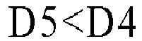
- Avantageusement, la première fraction est lisse, la deuxième portion étant frettée sur la première fraction, la deuxième fraction étant filetée et coopérant avec le taraudage de la troisième portion de l'insert de fixation.
- De cette manière, la localisation du filetage et du taraudage permet d'améliorer le bras de levier et d'améliorer la robustesse du dispositif.
- Avantageusement, les longueurs axiales L5 et L2 respectives de la deuxième fraction et de la deuxième portions sont reliés par la relation suivante

- De manière préférentielle, l'organe de raccord comprend un moyen de serrage activable à l'aide d'un outil de serrage, l'organe de raccord comprenant en outre une première et une deuxième embases de protection disposée de part et d'autre axiale et au contact du moyen de serrage, la première embase étant disposée axialement au contact et entre la tige et le moyen de serrage.
- Avantageusement, la longueur axiale L4 de la première fraction et les longueurs axiales respectives L1 et L2 des première et deuxième portions sont reliés par la relation suivante :

- L'invention a également pour objet un véhicule comprenant un train de roues comportant une première et une deuxième roues, la première roue étant associée à un premier système de suspension et la deuxième roue étant associée à un deuxième système de suspension, les deux systèmes de suspension étant connectés entre eux par l'intermédiaire d'une barre anti-dévers du véhicule, la barre anti-dévers étant fixée aux systèmes de suspension par chacune de ses extrémités au moyen d'un dispositif de fixation tel que défini ci-dessus.
- D'autres buts, caractéristiques et avantages de l'invention apparaîtront à la lecture de la description suivante, donnée uniquement à titre d'exemple non limitatif, et faite en référence aux dessins annexés sur lesquels :
- [
Fig1 ] illustre un dispositif de fixation d'un système de suspension à la barre anti-dévers d'un véhicule selon l'art antérieur ; - [
Fig2 ] illustre une vue en coupe longitudinale du dispositif de fixation de lafigure 1 ; - [
Fig3 ] illustre un dispositif de fixation d'un système de suspension à la barre anti-dévers d'un véhicule selon l'invention ; et - [
Fig4 ] illustre une vue en coupe longitudinale d'un dispositif de fixation de lafigure 3 . - On a donc représenté sur la
figure 3 une vue en perspective partielle d'un véhicule automobile 15 équipé d'un ensemble anti-dévers 16 selon l'invention. - L'ensemble anti-dévers 16 comprend une barre anti-dévers 17 métallique, par exemple en acier, sensiblement en forme de U et de section circulaire. La barre anti-dévers 17 comprend ainsi deux bras latéraux identiques 17a, et un tronçon central 17b reliant les deux bras latéraux 17a par l'une de leurs extrémités. Chacun des bras latéraux 17a comprend ainsi une extrémité liée au tronçon central 17b et une extrémité libre creuse opposée 17c, cette extrémité libre 17c correspondant à une extrémité de la barre anti-dévers 17. Chacune des extrémités libres opposées 17c s'étend jusqu'à une tranche 17d formée par une surface latérale et comprenant une entrée donnant accès à l'intérieur de l'extrémité libre, cet intérieur étant formé par une paroi interne 17e.
- La barre anti-dévers 17 est fixée au châssis du véhicule 15 par des paliers 15a et 15b enserrant partiellement le tronçon central 17b.
- Le véhicule 15 comprend un système de suspension 18 d'un même train de roues avant ou arrière du véhicule 15 associé à chacune des roues. Le véhicule 15 comprend donc un système de suspension 18 pour la roue gauche et un système de suspension 18 pour la roue droite.
- Chaque système de suspension 18 est connecté à l'ensemble anti-dévers 16 par l'intermédiaire d'un dispositif de fixation 19. Plus précisément, les dispositifs de fixation 19 permettent chacun de connecter un système de suspension 18 à une extrémité 17c creuse d'un bras latéral 17a de la barre anti-dévers 17.
- Par la suite, on ne décrira que l'un des dispositifs de fixation 19, par exemple le dispositif de fixation 19 de la roue gauche, l'ensemble de ce qui sera décrit étant symétrique et identique pour le côté droit. Un tel dispositif de fixation 19 est illustré en coupe longitudinale partielle sur la
figure 4 . L'extrémité libre 17c creuse gauche de la barre anti-dévers 17 est ainsi illustrée sur lafigure 4 et s'étend selon un axe B longitudinal. La surface latérale formant la tranche d'extrémité 17d est ainsi orthogonale à l'axe B. - Le dispositif de fixation 19 comprend une biellette 20 et un moyen de fixation 21 de la biellette à la barre anti-dévers 17. Plus précisément, le moyen de fixation 21 est un moyen de fixation de la biellette 20 à l'extrémité creuse 17c d'un bras latéral 17a de la barre anti-dévers 17.
- La biellette 20 est une tige métallique comportant une première extrémité formée par une première rotule 21a et une deuxième extrémité opposée formée par une seconde rotule 21b. La première rotule 21a connecte la biellette 20 à la barre anti-dévers 17, et plus précisément à l'extrémité creuse 17c d'un bras latéral 17a de la barre anti-dévers 17, tandis que la seconde rotule 21b connecte la biellette 20 au système de suspension 18. Les rotules 21a et 21b permettent ainsi à la biellette 20 de s'orienter en fonction du mouvement relatif du système de suspension 18 par rapport à la barre anti-dévers 17.
- Le moyen de fixation 21 comprend un insert de fixation 22 et un organe de raccord 23 de la biellette à l'insert de fixation illustrés en coupe longitudinale partielle sur la
figure 4 . - L'insert de fixation 22 comprend une tête d'appui 22a et un corps cylindrique 22b de section sensiblement circulaire et de diamètre inférieur ou égal au diamètre de la section circulaire de la barre anti-dévers 17 défini entre les parois intérieures 17e opposées d'un plan orthogonal à l'axe B de la barre anti-dévers 17. La tête d'appui 22a constitue l'une des extrémités du corps cylindrique 22b et forme une collerette de diamètre supérieur au diamètre respectivement du corps cylindrique 22b et de la section circulaire de la barre anti-dévers 17. Une coupe longitudinale de l'insert de fixation 22 a donc sensiblement une forme de « T ».
- L'insert de fixation 22 est ainsi introduit partiellement dans l'extrémité creuse 17c d'un bras latéral 17a de la barre anti-dévers 17. Plus précisément, l'introduction de l'insert de fixation 22 dans l'extrémité 17c de la barre anti-dévers 17 se fait par l'insertion du corps cylindrique 22b dans la barre 17 par la tranche d'extrémité 17d. La tête d'appui 22a bloque l'introduction de l'insert 22 dans la barre 17, et s'appuie contre la tranche 17d de l'extrémité 17c de la barre anti-dévers 17. En d'autres termes, la tête d'appui 22a est positionnée contre la tranche 17d de l'extrémité 17c de la barre anti-dévers 17 et dans son prolongement axial. Ainsi, l'insert de fixation 22 et l'extrémité creuse 17c du bras latéral 17b de la barre anti-dévers 17 s'étendent selon le même axe B portant le centre de leurs section circulaire respective. Le corps cylindrique 22b comprend donc une surface externe 24 en regard de la paroi interne 17e de l'extrémité 17c de la barre anti-dévers 17. Cette surface externe 24 définit une partie externe 24 de l'insert de fixation 22.
- La fixation de l'insert 22 à la barre anti-dévers 17 se fait par une soudure 22c par résistance électrique au niveau du contact entre la tête d'appui 22a de l'insert 22 et la tranche 17d de l'extrémité 17c de la barre anti-dévers 17, comme illustré sur la
figure 4 . La soudure est donc réalisée en des points situés sur une surface de la tête d'appui 22a en regard de l'extrémité 17c de la barre anti-dévers 3, et sur la tranche 17d de l'extrémité 17c. - La partie externe 24 a donc une section circulaire de diamètre inférieur au diamètre de la section circulaire de la barre anti-dévers 17 défini par la paroi intérieure 17e. Toutefois, la partie externe 24 comprend en outre au moins une excroissance radiale 25. L'au moins une excroissance radiale 25 est de préférence annulaire, et s'étend radialement suffisamment pour établir un contact avec la paroi intérieure 17e de la barre anti-dévers 17. L'au moins une excroissance radiale 25 confère donc ponctuellement en sa position axiale au corps cylindrique 22b une section circulaire de diamètre égal au diamètre de la paroi intérieure 17e de la barre anti-dévers 17.
- Ainsi, l'au moins une excroissance radiale 25 du corps cylindrique 22b constitue pour l'insert de fixation 22 au moins un point d'appui supplémentaire sur la barre anti-dévers 17, en plus de la soudure. De cette façon, les efforts et moments subis par la barre anti-dévers 17 et transmis par les roues et les systèmes de suspension 18 ne sont plus intégralement repris par la soudure 22c, mais également par les points de la barre 17 en contact de l'au moins une excroissance radiale 25. La soudure 22c est donc ménagée, et le dispositif de fixation 19 gagne en robustesse.
- L'au moins une excroissance 25 est positionnée de préférence du côté de la partie externe 24 opposée à la tête d'appui 22a afin d'optimiser l'efficacité du bras de levier.
- L'exemple illustré sur la
figure 4 comprend une première excroissance 25a et une deuxième excroissance 25b, la première excroissance 25a étant disposée à l'opposé de la tête d'appui 22a, et la deuxième excroissance 25b étant disposée entre la première excroissance 25a et la tête d'appui 22a. - De préférence, la somme des longueurs axiales des au moins une excroissances radiales 25 est inférieure à la moitié de la longueur totale du corps cylindrique 22a. De cette façon, l'insert de fixation 22 est allégé, les efforts nécessaires à l'insertion de l'insert de fixation 22 dans la barre anti-dévers 17 sont réduits tout en garantissant une robustesse améliorée.
- Enfin, l'au moins une excroissance 25, c'est-à-dire dans l'exemple illustré les excroissances 25a et 25b, permettent en outre d'assurer un meilleur centrage de l'insert de fixation 22 dans l'extrémité 17c de la barre anti-dévers 17, de façon à garantir le caractère coaxial selon l'axe B des éléments du dispositif de fixation 19 selon l'invention. De cette manière, le centrage de la première rotule 21a est amélioré.
- L'insert de fixation 22 est borgne. En d'autres termes, une cavité cylindrique 22d est pratiquée dans l'insert 22, cette cavité cylindrique 22d traversant l'insert 22 et débouchant au niveau de la tête d'appui 22a sur l'extérieur de l'insert 22. La cavité 22d est en revanche fermée sur son extrémité opposée à la tête d'appui 22a. La cavité 22d constitue donc un logement dont l'accès est constitué par une partie débouchante sur la tête d'appui 22a.
- La cavité 22d est cylindrique et est définie par une paroi interne 26 de l'insert 22 de section circulaire et dont le centre est porté par l'axe B.
- L'insert de fixation 22 comprend donc une partie interne 26 définie par la paroi interne 26 de la cavité 22d, et une partie externe 24 définie par la surface externe 24 du corps cylindrique 22b.
- La partie interne 26 comprend une première portion 26a de diamètre D1 et de longueur axiale L1 selon l'axe B, une deuxième portion 26b de diamètre D2 et de longueur axiale L2 selon l'axe B et une troisième portion 26c de diamètre D3 et de longueur axiale L3 selon l'axe B.
- La première portion 26a s'étend axialement entre la partie débouchante de la cavité 22d sur la tête d'appui 22a et la deuxième portion 26b, située à une longueur axiale L1 de la partie débouchante de la cavité 22d.
- La troisième portion 26c s'étend depuis l'extrémité fermée de la cavité 22d jusqu'à la deuxième portion 26b, située à une longueur axiale L3 de ladite extrémité fermée de la cavité 22d.
- La deuxième portion 26b est axialement positionnée et s'étend axialement entre la première portion 26a et la troisième portion 26b.
- Les diamètres D1, D2, D3 respectifs des première, deuxième et troisième portions 26a, 26 et 26c sont liés par la relation :

- Les premières et deuxièmes portions 26a et 26b ont des parois lisses, tandis que la troisième portion 26c est partiellement taraudée. En effet, la troisième portion 26c comprend un taraudage s'étendant axialement depuis la deuxième portion 26b jusqu'en un point axialement éloigné de la deuxième portion 26b d'une longueur inférieure à L3, la partie restante de la troisième portion 26c comprenant des parois lisses.
- L'organe de raccord 23 est fixé à la première rotule 21a de la biellette 20, et comprend un soufflet de protection 27, un moyen de serrage 28 et une tige 29 alignés selon l'axe B, de sorte que l'organe de raccord 23 s'étend le même axe B que la cavité 22d, l'insert de fixation 22 et l'extrémité 17c de la barre anti-dévers 17.
- Le moyen de serrage 28 comprend par exemple une couronne hexagonale destinée à servir de prise à un outil de serrage tel qu'une clé à molette.
- Le soufflet de protection 27 est disposé de façon connue autour d'un filet de matière 27a illustré en pointillés sur la
figure 4 reliant le moyen de serrage 28 à la première rotule 21a. De cette façon, le soufflet 27 protège la rotule 21a d'un choc avec l'outil de serrage lors du serrage de l'organe de raccord 23, et protège également la rotule 21a d'éventuelles agressions extérieures telles que des liquides, du sable ou de la poussière. - L'organe de raccord 23 comprend en outre une première embase 30 et une deuxième embase 31 alignées selon l'axe B avec la tige 29, le moyen de serrage 28, et le soufflet de protection 27 associé au filet de matière 27a.
- La première embase 30 est disposée axialement entre et au contact du moyen de serrage 28 et de la tige 29. La deuxième embase 31 est disposée axialement entre et au contact du moyen de serrage 28 et du soufflet de protection 27.
- La première embase 30 comprend une surface 30a orthogonale à l'axe B plane reposant contre la tête d'appui 22a, cette surface 30a participant à la transmission des efforts et moments provenant du système de suspension 18 à l'insert 22.
- La deuxième embase 31 est symétrique et identique à la première embase par rapport au moyen de serrage 28, la deuxième embase 31 comprenant une surface 31a orthogonale à l'axe B plane au contact du soufflet de protection 27.
- Les embases 30 et 31 ont une dimension radiale supérieure au diamètre du moyen de serrage 28, et permettent ainsi de protéger les éléments du dispositif de fixation 19 lors de l'utilisation de l'outil de serrage sur le moyen de serrage 28. En particulier, la première embase 30 protège un revêtement de la barre anti-dévers 17 constitué par une protection organique contre des agressions chimiques et/ou mécaniques provenant du milieu extérieur, telle qu'une protection époxy.
- La tige 29 s'étend depuis la surface 30a de la première embase 30, la première embase 30a reposant contre la tête d'appui 22a.
- La tige 29 a une section circulaire orthogonale à l'axe B. La tige 29 comprend une première fraction 29a de diamètre D4 et de longueur axiale L4 selon l'axe B, et une deuxième fraction 29b de diamètre D5 et de longueur axiale L5 selon l'axe B.
- Les diamètres D4 et D5 respectifs des première et deuxième fractions 29a et 29b sont liés par la relation :

- La première fraction 29a est disposée axialement entre le moyen de serrage 28 et la deuxième fraction 29b, et plus précisément entre la première embase 30 et la deuxième fraction 29b, la deuxième fraction 29b formant l'extrémité de l'organe de raccord 23 opposée à la tête d'appui 22a.
- La première fraction 29a est lisse tandis que la deuxième fraction 29b est filetée.
- La tige 29 est configurée pour s'introduire dans la partie interne 26 de l'insert 22 et coopérer avec l'insert de fixation 22. Plus précisément, le diamètre D5 de la deuxième fraction 29b est sensiblement égal au diamètre D3 de la troisième portion 26c. De plus, le filetage de la deuxième fraction 29b est apte à coopérer avec le taraudage de la troisième portion 26c. Ainsi, la deuxième fraction 29b est configurée pour coopérer avec la troisième portion 26c pour la solidarisation de l'insert de fixation 22 avec l'organe de raccord 23.
- De plus, la longueur axiale du taraudage de la troisième portion 26c est inférieure à la longueur axiale L3 de cette troisième portion 26c, de sorte que la troisième portion 26c comprend une partie axiale lisse.
- En outre, le diamètre D4 de la première fraction 29a est sensiblement égal au diamètre D2 de la deuxième portion 26b, supérieur au diamètre D3, et inférieur au diamètre D1 de la première portion 26a. De la sorte, la deuxième portion 26b est configurée pour être frettée sur la première fraction 29a lors de l'introduction de la tige 29 dans la cavité 26 de l'insert de fixation 22. Ainsi, le taraudage et le filetage sont moins sollicités dans la reprise des efforts et moments extérieurs, de façon à éviter sa casse. La solidarisation de l'insert de fixation 22 à l'organe de raccord 23 se fait donc d'une part par frettage de la deuxième portion 26b sur une partie de la première fraction 29a et d'autre part par coopération des filetage et taraudage respectifs de la deuxième fraction 29b et de la troisième portion 26c. L'appui de la première embase 30 sur la tête d'appui 22a constitue en outre un dernier moyen de solidarisation de l'insert 22 à l'organe de raccord 23, permettant de soulager le filetage/taraudage.
- Les longueurs axiales L5 et L2 respectives de la deuxième fraction 29b, de la première et de la deuxième portions 26a et 26b, sont reliés par la relation suivante :

- De cette façon, lors de l'introduction de la tige 29 de l'organe de raccord 23 dans la cavité 22d de l'insert de fixation 22, le filetage de la deuxième fraction 29b s'engage de quelques pas avec le taraudage de la troisième portion 26c avant que le frettage ne soit possible. De cette manière, une longueur de filetage suffisante est engagée dans le taraudage pour résister à l'effort axial de frettage sans que le filetage-taraudage ne soit endommagé.
- De plus, la longueur axiale de la tige 29, égale à la somme de la longueur axiale L4 de la première fraction et de la longueur axiale L5 de la deuxième fraction 29b filetée, est inférieure à la longueur axiale entre l'extrémité de la tête d'appui 22a au contact de la première embase 30 et l'extrémité axiale du taraudage de la troisième portion 26c au contact de la partie axiale lisse de la troisième portion 26c, de sorte que le filetage ne bute pas au fond du taraudage.
- Enfin, la longueur axiale L4 de la première fraction 29a et les longueurs axiales respectives L1 et L2 des première et deuxième portions 26a et 26b sont reliés par la relation suivante :

- Ainsi, l'organe de raccord 23 et l'insert de fixation 22 sont configurés pour que la première embase 30 soit plaquée contre la tête d'appui 22a avant que la longueur maximale de frettage possible ne soit atteinte, c'est-à-dire avant que la première fraction 29a ne bute contre une surface orthogonale à l'axe B de la troisième portion 26c.
- De plus, de ce fait, la zone de la tige 29 comprise entre la première embase 30 et le premier filet du filetage de la deuxième fraction 29b en prise avec le taraudage de la troisième portion 26c constitue une réserve élastique de l'assemblage pour éviter le dévissage lorsque les sollicitations imposées à l'ensemble sont très importantes.
- Enfin, la position du filetage-taraudage des deuxième fraction et troisième portion est relativement éloignée du point de soudure, de sorte que l'échauffement nécessaire à la soudure ne risque pas d'endommager le filetage-taraudage.
- Dans un autre mode de réalisation, la solidarisation entre l'insert de fixation 22 et l'extrémité 17c de la barre anti-dévers 17 se fait par sertissage entre les surfaces de contact, de manière à éviter la soudure. Par exemple, le sertissage peut se faire par déformation de la barre anti-dévers 17 axialement entre les deux excroissances 25a et 25b.
- Encore dans un autre mode de réalisation, le frettage peut être supprimé, sans pour autant modifier les caractéristiques relatives à la longueur L4, de manière à réduire les coûts de fabrication pour les applications ayant un niveau de sollicitations moins élevé.
Claims (10)
- Dispositif de fixation (19) d'une extrémité (17c) d'une barre anti-dévers (17) d'un véhicule (15) à un système de suspension (18) du véhicule, comprenant une biellette (20) destinée à être connectée au système de suspension (18) et un moyen de fixation (21) de la biellette (20) à la barre anti-dévers (17), la biellette (20) comportant une extrémité équipée d'une rotule (21a), le moyen de fixation (21) comprenant un organe de raccord (23) fixé à la rotule (21a) et un insert de fixation (22) comportant un corps cylindrique (22b) s'étendant selon un axe (B) et une tête d'appui (22a) formée sur un bout du corps cylindrique (22b), la tête d'appui (22a) reposant contre l'extrémité (17c) de la barre anti-dévers (17) et le corps cylindrique (22b) étant inséré dans l'extrémité (17c) de la barre anti-dévers (17), l'insert de fixation (22) comprenant une partie interne (26) débouchant sur la tête d'appui (22a) et recevant une tige (29) de l'organe de raccord (23), le corps cylindrique (22b) comprenant une partie externe (24) en regard de l'intérieur (17e) de la barre anti-dévers (17), caractérisé en ce que la partie externe (24) du corps cylindrique (22a) comprend au moins une excroissance (25, 25a, 25b) s'étendant radialement pour être au contact de l'intérieur (17e) de la barre anti-dévers (17).
- Dispositif de fixation selon la revendication 1, dans lequel la somme des longueurs axiales des au moins une excroissance radiale (25, 25a, 25b) est inférieure à la moitié de la longueur axiale totale du corps cylindrique (25b).
- Dispositif de fixation selon l'une des revendications 1 ou 2, dans lequel la partie interne (26) comprend une première portion (26a) de diamètre D1 et de longueur axiale L1, une deuxième portion (26b) de diamètre D2 et de longueur axiale L2, et une troisième portion (26c) de diamètre D3 et de longueur axiale L3, la deuxième portion (26b) étant axialement positionnée entre la première portion (26a) et la troisième portion (26c), la première portion (26a) comprenant l'ouverture débouchante de la partie interne (26) sur la tête d'appui (22a), les diamètres des trois portions (26a, 26b, 26c) étant liés par la relation :

- Dispositif de fixation selon la revendication 3, dans lequel la première portion (26a) et la deuxième portion (26b) sont lisses, et la troisième portion (26c) est partiellement taraudée, le taraudage étant disposé au contact axial de la deuxième portion (26b).
- Dispositif de fixation selon l'une quelconque des revendications 1 à 4, dans lequel la tige (29) de l'organe de raccord (23) comprend une première fraction (29a) de diamètre D4 et de longueur L4 et une deuxième fraction (29b) de diamètre D5 et de longueur L5, la première fraction (29a) étant disposée entre la tête d'appui (22a) et la deuxième fraction (29b), les diamètres des deux fractions (29a, 29b) étant liés par la relation :

- Dispositif selon les revendications 4 et 5, dans lequel la première fraction (29a) est lisse, la deuxième portion (26b) étant frettée sur la première fraction (29a), la deuxième fraction (29b) étant filetée et coopérant avec le taraudage de la troisième portion (26c) de l'insert de fixation (22).
- Dispositif de fixation selon la revendication 6, dans lequel les longueurs axiales L5 et L2 respectives de la deuxième fraction (29b) et de la deuxième portion (26b) sont reliés par la relation suivante :

- Dispositif de fixation selon la revendication 7, dans lequel l'organe de raccord (23) comprend un moyen de serrage (28) activable à l'aide d'un outil de serrage, l'organe de raccord (23) comprenant en outre une première et une deuxième embases (30 et 31) de protection disposée de part et d'autre axiale et au contact du moyen de serrage (28), la première embase (30) étant disposée axialement au contact et entre la tige (29) et le moyen de serrage (28).
- Dispositif de fixation selon la revendication 8, dans lequel la longueur axiale L4 de la première fraction (29a) et les longueurs axiales respectives L1 et L2 des première et deuxième portions (26a et 26b) sont reliés par la relation suivante :

- Véhicule (15) comprenant un train de roue comportant une première et une deuxième roues, la première roue étant associé à un premier système de suspension (18) et la deuxième roue étant associée à un deuxième système de suspension (18), les deux systèmes de suspension (18) étant connectés entre eux par l'intermédiaire d'une barre anti-dévers (17) du véhicule (15), la barre anti-dévers (17) étant fixé aux systèmes de suspension (18) en chacune de ses extrémités (17c) par un dispositif de fixation selon l'une quelconque des revendications 1 à 9.
Applications Claiming Priority (1)
| Application Number | Priority Date | Filing Date | Title |
|---|---|---|---|
| FR2214291A FR3144056B1 (fr) | 2022-12-22 | 2022-12-22 | Dispositif de fixation d’une extrémité d’une barre anti-dévers à un système de suspension d’un véhicule, et véhicule associé. |
Publications (1)
| Publication Number | Publication Date |
|---|---|
| EP4389473A1 true EP4389473A1 (fr) | 2024-06-26 |
Family
ID=85726840
Family Applications (1)
| Application Number | Title | Priority Date | Filing Date |
|---|---|---|---|
| EP23218724.5A Pending EP4389473A1 (fr) | 2022-12-22 | 2023-12-20 | Dispositif de fixation d'une extrémité d'une barre anti-dévers à un système de suspension d'un véhicule, et véhicule associé |
Country Status (2)
| Country | Link |
|---|---|
| EP (1) | EP4389473A1 (fr) |
| FR (1) | FR3144056B1 (fr) |
Cited By (1)
| Publication number | Priority date | Publication date | Assignee | Title |
|---|---|---|---|---|
| EP4635760A1 (fr) * | 2024-04-15 | 2025-10-22 | Muhr und Bender KG | Stabilisateur pour un train de roulement d'un véhicule automobile et procédé de fabrication d'un stabilisateur |
Citations (2)
| Publication number | Priority date | Publication date | Assignee | Title |
|---|---|---|---|---|
| EP3552851A1 (fr) * | 2018-04-09 | 2019-10-16 | Engineering Developments for Automotive Industry, S.L. | Dispositif de fixation pour la fixation d'une tige d'accouplement avec une barre stabilisatrice creuse |
| DE102019103573A1 (de) * | 2019-02-13 | 2020-08-13 | Muhr Und Bender Kg | Stabilisatoranordnung für ein fahrwerk eines kraftfahrzeugs |
-
2022
- 2022-12-22 FR FR2214291A patent/FR3144056B1/fr active Active
-
2023
- 2023-12-20 EP EP23218724.5A patent/EP4389473A1/fr active Pending
Patent Citations (2)
| Publication number | Priority date | Publication date | Assignee | Title |
|---|---|---|---|---|
| EP3552851A1 (fr) * | 2018-04-09 | 2019-10-16 | Engineering Developments for Automotive Industry, S.L. | Dispositif de fixation pour la fixation d'une tige d'accouplement avec une barre stabilisatrice creuse |
| DE102019103573A1 (de) * | 2019-02-13 | 2020-08-13 | Muhr Und Bender Kg | Stabilisatoranordnung für ein fahrwerk eines kraftfahrzeugs |
Cited By (1)
| Publication number | Priority date | Publication date | Assignee | Title |
|---|---|---|---|---|
| EP4635760A1 (fr) * | 2024-04-15 | 2025-10-22 | Muhr und Bender KG | Stabilisateur pour un train de roulement d'un véhicule automobile et procédé de fabrication d'un stabilisateur |
Also Published As
| Publication number | Publication date |
|---|---|
| FR3144056B1 (fr) | 2025-02-28 |
| FR3144056A1 (fr) | 2024-06-28 |
Similar Documents
| Publication | Publication Date | Title |
|---|---|---|
| EP2751437B1 (fr) | Dispositif de liaison d'une colonne de direction avec un boitier de direction. | |
| FR3144056A1 (fr) | Dispositif de fixation d’une extrémité d’une barre anti-dévers à un système de suspension d’un véhicule, et véhicule associé. | |
| EP4389474A1 (fr) | Dispositif de fixation d'une extrémité d'une barre anti-dévers à un système de suspension d'un véhicule, et véhicule associé | |
| EP3437940B1 (fr) | Adaptateur pour un essuie-glace de véhicule automobile, et ensemble comportant un tel adaptateur | |
| EP1051894B1 (fr) | Dispositif d'adaptation pour barre d'attelage de tracteur | |
| EP2004429B1 (fr) | Train arriere pour vehicule automobile | |
| FR3099463A1 (fr) | Dispositif de montage d’un axe sur une chape pour une turbomachine d’aeronef | |
| FR2810275A1 (fr) | Dispositif de fixation d'un support de palier d'une barre anti-devers a un element de structure d'un vehicule automobile | |
| FR3126380A1 (fr) | Adaptateur d’un système d’essuyage. | |
| FR3099089A1 (fr) | Palier et pièce de réglage pour train multi-bras | |
| EP4067125A1 (fr) | Bague de maintien d'une biellette de barre stabilisatrice d'un vehicule automobile | |
| EP0484215B1 (fr) | Compresseur de ressorts | |
| EP0312425B1 (fr) | Bras oscillant tiré de suspension pour roue arrière d'un véhicule automobile | |
| EP1104736B1 (fr) | Dispositif d'assemblage d'un pignon de direction avec un étrier | |
| EP0943826B1 (fr) | Dispositif d'assemblage d'une biellette de liaison dans un alésage d'une barre anti-devers de véhicule | |
| EP1179469A1 (fr) | Colonne de direction pour un système de direction de véhicule automobile | |
| EP4455497A1 (fr) | Bielle réglable en longueur de façon continue et procédé de montage de la bielle réglable | |
| FR2753932A1 (fr) | Suspension de roue de vehicule automobile | |
| FR2701236A1 (fr) | Suspension à bras tiré et filtrage des chocs longitudinaux, notamment pour une roue arrière de véhicule automobile. | |
| FR3161929A1 (fr) | Joint de cardan pour véhicule automobile | |
| FR3158768A1 (fr) | Ecrou de serrage doté d’au moins une languette de verrouillage anti-desserrement | |
| FR3144807A1 (fr) | Ensemble de tringlerie pour diriger des roues d'un véhicule automobile | |
| FR3153116A1 (fr) | Rotule de pivot pour véhicule automobile et procédé de fabrication | |
| FR2753497A1 (fr) | Paliers de barres anti-devers pour vehicules automobiles ou poids lourds | |
| EP4339075A1 (fr) | Titre de l'invention : ensemble de structure de véhicule automobile à corps creux |
Legal Events
| Date | Code | Title | Description |
|---|---|---|---|
| PUAI | Public reference made under article 153(3) epc to a published international application that has entered the european phase |
Free format text: ORIGINAL CODE: 0009012 |
|
| STAA | Information on the status of an ep patent application or granted ep patent |
Free format text: STATUS: THE APPLICATION HAS BEEN PUBLISHED |
|
| AK | Designated contracting states |
Kind code of ref document: A1 Designated state(s): AL AT BE BG CH CY CZ DE DK EE ES FI FR GB GR HR HU IE IS IT LI LT LU LV MC ME MK MT NL NO PL PT RO RS SE SI SK SM TR |
|
| STAA | Information on the status of an ep patent application or granted ep patent |
Free format text: STATUS: REQUEST FOR EXAMINATION WAS MADE |
|
| 17P | Request for examination filed |
Effective date: 20241203 |
|
| RBV | Designated contracting states (corrected) |
Designated state(s): AL AT BE BG CH CY CZ DE DK EE ES FI FR GB GR HR HU IE IS IT LI LT LU LV MC ME MK MT NL NO PL PT RO RS SE SI SK SM TR |