EP4389435A2 - Printing apparatus - Google Patents
Printing apparatus Download PDFInfo
- Publication number
- EP4389435A2 EP4389435A2 EP23217623.0A EP23217623A EP4389435A2 EP 4389435 A2 EP4389435 A2 EP 4389435A2 EP 23217623 A EP23217623 A EP 23217623A EP 4389435 A2 EP4389435 A2 EP 4389435A2
- Authority
- EP
- European Patent Office
- Prior art keywords
- air blowing
- heating
- medium
- supporting surface
- unit
- Prior art date
- Legal status (The legal status is an assumption and is not a legal conclusion. Google has not performed a legal analysis and makes no representation as to the accuracy of the status listed.)
- Granted
Links
Images


Classifications
-
- B—PERFORMING OPERATIONS; TRANSPORTING
- B41—PRINTING; LINING MACHINES; TYPEWRITERS; STAMPS
- B41J—TYPEWRITERS; SELECTIVE PRINTING MECHANISMS, i.e. MECHANISMS PRINTING OTHERWISE THAN FROM A FORME; CORRECTION OF TYPOGRAPHICAL ERRORS
- B41J11/00—Devices or arrangements of selective printing mechanisms, e.g. ink-jet printers or thermal printers, for supporting or handling copy material in sheet or web form
- B41J11/0015—Devices or arrangements of selective printing mechanisms, e.g. ink-jet printers or thermal printers, for supporting or handling copy material in sheet or web form for treating before, during or after printing or for uniform coating or laminating the copy material before or after printing
- B41J11/002—Curing or drying the ink on the copy materials, e.g. by heating or irradiating
- B41J11/0021—Curing or drying the ink on the copy materials, e.g. by heating or irradiating using irradiation
- B41J11/00216—Curing or drying the ink on the copy materials, e.g. by heating or irradiating using irradiation using infrared [IR] radiation or microwaves
-
- B—PERFORMING OPERATIONS; TRANSPORTING
- B41—PRINTING; LINING MACHINES; TYPEWRITERS; STAMPS
- B41J—TYPEWRITERS; SELECTIVE PRINTING MECHANISMS, i.e. MECHANISMS PRINTING OTHERWISE THAN FROM A FORME; CORRECTION OF TYPOGRAPHICAL ERRORS
- B41J2/00—Typewriters or selective printing mechanisms characterised by the printing or marking process for which they are designed
- B41J2/005—Typewriters or selective printing mechanisms characterised by the printing or marking process for which they are designed characterised by bringing liquid or particles selectively into contact with a printing material
- B41J2/01—Ink jet
-
- B—PERFORMING OPERATIONS; TRANSPORTING
- B41—PRINTING; LINING MACHINES; TYPEWRITERS; STAMPS
- B41J—TYPEWRITERS; SELECTIVE PRINTING MECHANISMS, i.e. MECHANISMS PRINTING OTHERWISE THAN FROM A FORME; CORRECTION OF TYPOGRAPHICAL ERRORS
- B41J11/00—Devices or arrangements of selective printing mechanisms, e.g. ink-jet printers or thermal printers, for supporting or handling copy material in sheet or web form
- B41J11/0015—Devices or arrangements of selective printing mechanisms, e.g. ink-jet printers or thermal printers, for supporting or handling copy material in sheet or web form for treating before, during or after printing or for uniform coating or laminating the copy material before or after printing
-
- B—PERFORMING OPERATIONS; TRANSPORTING
- B41—PRINTING; LINING MACHINES; TYPEWRITERS; STAMPS
- B41J—TYPEWRITERS; SELECTIVE PRINTING MECHANISMS, i.e. MECHANISMS PRINTING OTHERWISE THAN FROM A FORME; CORRECTION OF TYPOGRAPHICAL ERRORS
- B41J11/00—Devices or arrangements of selective printing mechanisms, e.g. ink-jet printers or thermal printers, for supporting or handling copy material in sheet or web form
- B41J11/0015—Devices or arrangements of selective printing mechanisms, e.g. ink-jet printers or thermal printers, for supporting or handling copy material in sheet or web form for treating before, during or after printing or for uniform coating or laminating the copy material before or after printing
- B41J11/002—Curing or drying the ink on the copy materials, e.g. by heating or irradiating
- B41J11/0022—Curing or drying the ink on the copy materials, e.g. by heating or irradiating using convection means, e.g. by using a fan for blowing or sucking air
-
- B—PERFORMING OPERATIONS; TRANSPORTING
- B41—PRINTING; LINING MACHINES; TYPEWRITERS; STAMPS
- B41J—TYPEWRITERS; SELECTIVE PRINTING MECHANISMS, i.e. MECHANISMS PRINTING OTHERWISE THAN FROM A FORME; CORRECTION OF TYPOGRAPHICAL ERRORS
- B41J3/00—Typewriters or selective printing or marking mechanisms characterised by the purpose for which they are constructed
- B41J3/407—Typewriters or selective printing or marking mechanisms characterised by the purpose for which they are constructed for marking on special material
Definitions
- the present disclosure relates to a printing apparatus.
- JP-A-2020-104320 discloses a printing apparatus including a printing unit that performs printing by ejecting liquid to a medium, a supporting part facing the printing unit, a heating unit that heats the printed medium, and a downstream supporting part facing the heating unit.
- the supporting part includes a supporting surface that supports the medium. The medium after the printing is conveyed downward from the supporting part toward the downstream supporting part.
- the heating unit includes a portion located on the upper side of the supporting surface.
- the medium is conveyed downward in a curved manner from the supporting part toward the downstream supporting part. Therefore, the printing apparatus performs printing mainly for a flexible medium such as fabric and roll paper.
- printing apparatuses perform printing not only on flexible mediums, but also on rigid mediums such as thick paper and board paper.
- the rigid medium is not curved, and is therefore conveyed straight along the supporting surface.
- the rigid medium may interfere with the heating unit, the air blowing unit and the like during the conveyance along the supporting surface. In view of this, when printing is performed on the rigid medium, it is necessary to detach the heating unit, the air blowing unit and the like, but such a detaching operation is time consuming, and reduces the usability.
- a printing apparatus for solving the above-described problems includes a printing unit configured to perform printing by ejecting liquid to a medium conveyed, a supporting part facing the printing unit, and including a supporting surface configured to support the medium, a downstream supporting part located downstream of the supporting part in a medium conveyance direction, and including a downstream supporting surface obliquely extending with respect to the supporting surface, and a heating unit facing the downstream supporting part.
- the heating unit includes: a heating part configured to heat the medium, and a heating case configured to house the heating part, the heating case includes a heating top portion located at an uppermost position in the heating case, and the heating top portion is located at a position below the supporting surface.
- a printing apparatus for solving the above-described problems includes a printing unit configured to perform printing by ejecting liquid to a medium conveyed, a supporting part facing the printing unit, and including a supporting surface configured to support the medium, an upstream supporting part located upstream of the supporting part in a medium conveyance direction, and including an upstream supporting surface obliquely extending with respect to the supporting surface, an air blowing unit facing the upstream supporting part.
- the air blowing unit includes an air blowing part configured to blow air toward the upstream supporting surface, and an air blowing case configured to house the air blowing part, the air blowing case includes an air blowing top portion located at an uppermost position in the air blowing case, and the air blowing top portion is located at a position below the supporting surface.
- the printing apparatus is an ink-jet printer that records images such as letters, photographs and diagrams by ejecting ink as an example of liquid to a medium such as fabric and a sheet, for example.
- the printing apparatus performs printing on a soft medium and a rigid medium as the medium.
- a printing apparatus 11 includes a feeding part 12.
- the feeding part 12 is configured to feed a soft medium S1 with flexibility.
- the feeding part 12 feeds the unused soft medium S1.
- the soft medium S1 is a medium such as fabric and thin paper. Therefore, the soft medium S1 can be bent and curved during conveyance.
- the soft medium S1 is fed from a roll R1 obtained by winding the soft medium S1, for example.
- the feeding part 12 includes a feeding shaft 13.
- the feeding shaft 13 holds the unused roll R1.
- the roll R1 held by the feeding shaft 13 rotates, the unused soft medium S1 is fed from the feeding part 12. Images are printed on the soft medium S1 fed from the feeding part 12.
- the printing apparatus 11 includes a winding unit 14.
- the winding unit 14 is configured to wind up the soft medium S1. Specifically, the winding unit 14 winds up the soft medium S1 fed from the feeding part 12. The winding unit 14 winds up the used soft medium S1. That is, an image is printed on the soft medium S1 in the process from the feeding of the soft medium S1 by the feeding part 12 to the winding of the soft medium S1 by the winding unit 14.
- the winding unit 14 includes a winding shaft 15.
- the winding shaft 15 holds the used roll R1.
- the used soft medium S1 is wound around the winding unit 14.
- the printing apparatus 11 includes a printing unit 16.
- the printing unit 16 is configured to print an image on a medium by ejecting liquid.
- the printing unit 16 prints an image on the soft medium S1, for example.
- the printing unit 16 may perform printing not only on the soft medium S1, but also on a rigid medium H1.
- the rigid medium H1 is thick paper, board paper and the like.
- the rigid medium H1 is not bent or curved during conveyance. Therefore, the rigid medium H1 is not fed from the feeding part 12, or wound by the winding unit 14.
- the rigid medium H1 is separately supplied to the printing unit 16 separately from the soft medium S1.
- the printing unit 16 includes a head 17.
- the head 17 includes a nozzle surface 19 at which one or more nozzles 18 open.
- the head 17 ejects liquid from the nozzle 18.
- the printing unit 16 includes a carriage 20.
- the carriage 20 is equipped with the head 17.
- the carriage 20 performs scanning with respect to the medium. Through the scanning of the carriage 20, the head 17 can eject the liquid over the entire width of the medium.
- the printing apparatus 11 is a so-called serial printer.
- the printing apparatus 11 may be a line printer of which the head 17 can eject liquid at the same time over the width of the medium.
- the printing apparatus 11 includes a supporting part 21.
- the supporting part 21 supports a medium. Specifically, the supporting part 21 supports the medium being conveyed.
- the supporting part 21 supports the medium from below.
- the supporting part 21 faces the printing unit 16. Thus, liquid is ejected from the printing unit 16 to the medium in the region supported by the supporting part 21.
- the supporting part 21 includes a supporting surface 22 that supports the medium.
- the supporting surface 22 is a surface that faces the printing unit 16. Specifically, the supporting surface 22 faces the nozzle surface 19. The supporting surface 22 makes contact with the medium.
- the supporting surface 22 faces upward, for example.
- the position of the supporting surface 22 in a vertical direction Z1 is a reference position A1. That is, the reference position A1 represents the height of the supporting surface 22.
- the supporting part 21 is located on the upper side of the feeding part 12.
- the supporting part 21 is located on the upper side of the winding unit 14.
- the soft medium S1 extending from the feeding part 12 to the winding unit 14 is provided across the supporting part 21.
- the printing apparatus 11 includes a conveyance unit 23.
- the conveyance unit 23 is configured to convey a medium.
- the conveyance unit 23 conveys the medium in a conveyance direction Y1 on the supporting surface 22. Therefore, the conveyance direction Y1 is a direction along the supporting surface 22.
- the conveyance unit 23 conveys the soft medium S1 in the conveyance direction Y1 on the supporting surface 22.
- the conveyance unit 23 conveys the rigid medium H1 in the conveyance direction Y1 on the supporting surface 22.
- the conveyance unit 23 is located upstream of the supporting part 21 in the conveyance direction Y1.
- the conveyance unit 23 may be located downstream of the supporting part 21 in the conveyance direction Y1.
- the conveyance unit 23 includes a first roller 24 and a second roller 25.
- the first roller 24 and the second roller 25 convey the medium by rotating with the medium sandwiched therebetween.
- the nip point of the first roller 24 and the second roller 25 is at the same height as the reference position A1.
- the first roller 24 and the second roller 25 sandwich the medium at the reference position A1.
- the first roller 24 and the second roller 25 sandwich the medium, and thus the medium is set in the printing apparatus 11.
- the soft medium S1 is set in the printing apparatus 11 by being provided across the supporting part 21 from the feeding part 12 to the winding unit 14.
- the rigid medium H1 is set in the printing apparatus 11 by being inserted between the first roller 24 and the second roller 25. At this time, the rigid medium H1 is set so as to protrude to the upstream side in the conveyance direction Y1 from the location on the supporting part 21.
- the printing apparatus 11 includes an upstream supporting part 26.
- the upstream supporting part 26 is located upstream of the supporting part 21 in the conveyance direction Y1.
- the upstream supporting part 26 is located at a position below the reference position A1.
- the upstream supporting part 26 supports the soft medium S1.
- the upstream supporting part 26 supports the soft medium S1 in the period from the feeding from the feeding part 12 to the sandwiching by the first roller 24 and the second roller 25.
- the upstream supporting part 26 does not support the rigid medium H1.
- the upstream supporting part 26 includes an upstream supporting surface 27 that supports the soft medium S1.
- the upstream supporting surface 27 is a surface that obliquely extends with respect to the supporting surface 22.
- the upstream supporting surface 27 is a surface that tilts obliquely upward in the direction from the feeding part 12 toward the supporting part 21.
- the printing apparatus 11 includes a downstream supporting part 28.
- the downstream supporting part 28 is located downstream of the supporting part 21 in the conveyance direction Y1.
- the downstream supporting part 28 is located at a position below the reference position A1.
- the downstream supporting part 28 supports the soft medium S1.
- the downstream supporting part 28 supports the soft medium S1 in the period until it is wound by the winding unit 14 after being supported by the supporting part 21.
- the downstream supporting part 28 does not support the rigid medium H1.
- the downstream supporting part 28 includes a downstream supporting surface 29 that supports the soft medium S1.
- the downstream supporting surface 29 is a surface that obliquely extends with respect to the supporting surface 22.
- the downstream supporting surface 29 is a surface that tilts obliquely downward in the direction from the supporting part 21 toward the winding unit 14.
- the printing apparatus 11 may include an air blowing unit 31.
- the air blowing unit 31 faces the upstream supporting part 26. Specifically, the air blowing unit 31 faces the upstream supporting surface 27.
- the air blowing unit 31 is configured to blow air to the soft medium S1.
- the air blowing unit 31 removes foreign matters from the soft medium S1 by blowing air to the soft medium S1. Specifically, the air blowing unit 31 removes foreign matters from the soft medium S1 before the printing. In this manner, the printing quality of the soft medium S1 is improved.
- the air blowing unit 31 includes an air blowing part 32.
- the air blowing part 32 blows air to the soft medium S1 supported by the upstream supporting part 26. Specifically, the air blowing part 32 blows air to the soft medium S1 in the portion located on the upstream supporting surface 27.
- the air blowing part 32 is a fan, for example.
- the air blowing unit 31 includes an air blowing case 33.
- the air blowing case 33 houses the air blowing part 32.
- the air blowing case 33 opens toward the upstream supporting part 26.
- the air blowing case 33 includes an air blowing top portion 34.
- the air blowing top portion 34 is a portion located at the uppermost position in the air blowing case 33.
- the air blowing top portion 34 is located at a position below the reference position A1. That is, the air blowing unit 31 is not located above the supporting surface 22.
- the air blowing unit 31 does not interfere with the rigid medium H1.
- the rigid medium H1 is set in the state where it extends straight to the upstream side in the conveyance direction Y1 from the location on the supporting part 21. In this manner, the printing apparatus 11 can perform printing on the rigid medium H1 without detaching the air blowing unit 31.
- it is not necessary to detach the air blowing unit 31 it is not necessary to ensure the housing space for the detached air blowing unit 31.
- the air blowing top portion 34 is located at the reference position A1. That is, the air blowing top portion 34 is located at the same height as the supporting surface 22. As a result, when setting the rigid medium H1, the air blowing top portion 34 can support the rigid medium H1 together with the supporting part 21. With the air blowing top portion 34 supporting the rigid medium H1, the posture of the rigid medium H1 is stabilized.
- the air blowing top portion 34 may include an air blowing top surface 35.
- the air blowing top surface 35 is the outer surface of the air blowing case 33.
- the air blowing top surface 35 is a surface facing upward in the air blowing case 33.
- the air blowing top surface 35 is located at the reference position A1. That is, the air blowing top surface 35 is located at the same height as the supporting surface 22.
- the air blowing top surface 35 supports the rigid medium H1. In this manner, the posture of the rigid medium H1 is easily stabilized.
- the air blowing case 33 may include an air blowing continuous surface 36 that is continuous with the air blowing top surface 35.
- the air blowing continuous surface 36 extends obliquely downward from the air blowing top surface 35.
- the air blowing continuous surface 36 extends parallel to the upstream supporting surface 27.
- the air blowing case 33 includes an air blowing extension portion 37.
- the air blowing extension portion 37 is a portion extending the air blowing top portion 34.
- the air blowing extension portion 37 includes an air blowing extension surface 38.
- the air blowing extension surface 38 is a surface extending the air blowing top surface 35.
- the air blowing extension surface 38 extends parallel to the air blowing top surface 35.
- the air blowing extension surface 38 is continuous with the air blowing top surface 35.
- the air blowing extension surface 38 is located at the reference position A1 as with the air blowing top surface 35.
- the air blowing extension portion 37 is configured to be displaced to an air blowing housing position P1 and an air blowing extension position P2.
- the air blowing extension portion 37 is displaced by rotating.
- the air blowing extension portion 37 is displaced by rotating around one end portion.
- the air blowing extension portion 37 rotates with a hinge 39.
- the air blowing extension portion 37 may be displaced not only by rotating but also by sliding, for example.
- the air blowing housing position P1 is a position where the air blowing extension portion 37 is housed in the air blowing case 33.
- the air blowing housing position P1 is a position where the air blowing extension portion 37 is set along the air blowing continuous surface 36.
- the air blowing extension portion 37 illustrated in FIG. 2 is located at the air blowing housing position P1.
- the air blowing extension position P2 is a position where the air blowing extension portion 37 extends the air blowing top portion 34.
- the air blowing extension position P2 is a position where the air blowing extension surface 38 is continuous with the air blowing top surface 35.
- the air blowing extension portion 37 illustrated in FIG. 3 is located at the air blowing extension position P2.
- the printing apparatus 11 may include a heating unit 41.
- the heating unit 41 faces the downstream supporting part 28. Specifically, the heating unit 41 faces the downstream supporting surface 29.
- the heating unit 41 is configured to heat the soft medium S1.
- the heating unit 41 dries the soft medium S1 by heating the soft medium S1. That is, the heating unit 41 dries the soft medium S1 after the printing. In this manner, the printing quality of the soft medium S1 is improved.
- the heating unit 41 includes a heating part 42.
- the heating part 42 heats the soft medium S1 supported by the downstream supporting part 28. Specifically, the heating part 42 heats the portion located on the downstream supporting surface 29 in the soft medium S1.
- the heating part 42 is an infrared ray heater, for example.
- the heating unit 41 may include a reflection plate 43.
- the reflection plate 43 reflects, toward the downstream supporting surface 29, the infrared ray emitted from the heating part 42. In this manner, the heating efficiency of the heating part 42 is improved.
- the heating unit 41 includes a heating case 44.
- the heating case 44 houses the heating part 42.
- the heating case 44 houses the reflection plate 43.
- the heating case 44 opens toward the downstream supporting part 28.
- the heating case 44 includes a heating top portion 45.
- the heating top portion 45 is a portion located at the uppermost position in the heating case 44.
- the heating top portion 45 is located at a position below the reference position A1. That is, the heating unit 41 is not located above the supporting surface 22.
- the heating unit 41 does not interfere with the rigid medium H1.
- the printing apparatus 11 can perform printing on the rigid medium H1 without detaching the heating unit 41.
- it is not necessary to detach the heating unit 41 it is not necessary to ensure a housing space for the detached heating unit 41.
- the heating top portion 45 is located at the reference position A1. That is, the heating top portion 45 is located at the same height as the supporting surface 22. In this manner, when ejecting the rigid medium H1, the heating top portion 45 can support the rigid medium H1 together with the supporting part 21. Thus, the posture of the rigid medium H1 is stabilized.
- the heating top portion 45 may include a heating top surface 46.
- the heating top surface 46 is an outer surface of the heating case 44.
- the heating top surface 46 is a surface facing upward in the heating case 44.
- the heating top surface 46 is located at the reference position A1. That is, the heating top surface 46 is located at the same height as the supporting surface 22.
- the heating top surface 46 supports the rigid medium H1. In this manner, the posture of the rigid medium H1 is easily stabilized.
- the heating case 44 may include a heating continuous surface 47 that is continuous with the heating top surface 46.
- the heating continuous surface 47 extends obliquely downward from the heating top surface 46.
- the heating continuous surface 47 extends parallel to the downstream supporting surface 29.
- the heating case 44 includes a heating extension portion 48.
- the heating extension portion 48 is a portion extending the heating top portion 45.
- the heating extension portion 48 includes a heating extension surface 49.
- the heating extension surface 49 is a surface extending the heating top surface 46.
- the heating extension surface 49 extends parallel to the heating top surface 46.
- the heating extension surface 49 is continuous with the heating top surface 46.
- the heating extension surface 49 is located at the reference position A1 as with the heating top surface 46. With the heating extension portion 48 extending the heating top portion 45, the heating top surface 46 and the heating extension surface 49 support the rigid medium H1. In this manner, the posture of the rigid medium H1 is easily stabilized.
- the heating extension portion 48 is configured to be displaced to a heating housing position Q1 and a heating extension position Q2.
- the heating extension portion 48 is displaced by rotating.
- the heating extension portion 48 is displaced by rotating around one end portion.
- the heating extension portion 48 rotates with a hinge 50.
- the heating extension portion 48 may be displaced not only by rotating but also by sliding, for example.
- the heating housing position Q1 is a position where the heating extension portion 48 is housed in the heating case 44.
- the heating housing position Q1 is a position where the heating extension portion 48 is set along the heating continuous surface 47.
- the heating extension portion 48 illustrated in FIG. 2 is located at the heating housing position Q1.
- the heating extension position Q2 is a position where the heating extension portion 48 extends the heating top portion 45.
- the heating extension position Q2 is a position where the heating extension surface 49 is continuous with the heating top surface 46.
- the heating extension portion 48 illustrated in FIG. 3 is located at the heating extension position Q2.
- the printing apparatus 11 may include an operation unit 61.
- the operation unit 61 is a touch panel, for example.
- the operation unit 61 may be a button, a lever, a switch, and the like.
- the user may select whether printing is performed on the soft medium S1 or the rigid medium H1 from the operation unit 61.
- the driving of the feeding part 12, the winding unit 14, the air blowing unit 31, the heating unit 41 and the like is also started.
- the air blowing extension portion 37 and the heating extension portion 48 may be displaced.
- the air blowing extension portion 37 may be displaced to the air blowing extension position P2 and the heating extension portion 48 may be displaced to the heating extension position Q2.
- the supporting surface 22, the air blowing extension surface 38, and the heating extension surface 49 are located at the reference position A1 and arranged on a straight line. In this manner, the rigid medium H1 is conveyed in a stable posture.
- the air blowing extension portion 37 may be displaced to the air blowing housing position P1 and the heating extension portion 48 may be displaced to the heating housing position Q1. In this manner, the air blowing extension portion 37 and the heating extension portion 48 are prevented from hindering the operation. In addition, regardless of the start and termination of the printing, the air blowing extension portion 37 and the heating extension portion 48 may be displaced when the operation unit 61 is operated. In addition, the user may manually displace the air blowing extension portion 37 and the heating extension portion 48 without using the operation unit 61.
- the air blowing extension surface 38 may also serve as the air blowing continuous surface 36.
- the air blowing extension portion 37 may make up the exterior of the air blowing case 33.
- the air blowing extension portion 37 exposes the inside of the air blowing case 33 when it is located at the air blowing extension position P2.
- the air blowing unit 31 is not used. Therefore, no problem occurs even when the inside of the air blowing case 33is exposed.
- the air blowing extension portion 37 is located at the air blowing housing position P1, the air blowing part 32 is covered by the air blowing case 33.
- the heating extension surface 49 may also serve as the heating continuous surface 47.
- the heating extension portion 48 may make up the exterior of the heating case 44.
- the heating extension portion 48 exposes the heating case 44 when it is located at the heating extension position Q2.
- the heating unit 41 is not used. Therefore, no problem occurs even when the heating case 44 is exposed.
- the heating extension portion 48 is located at the heating housing position Q1, the heating part 42 is covered by the heating case 44.
- the liquid ejected by the head 17 is not limited to ink, but may be a liquid member obtained by dispersing or mixing particles of a functional material in liquid.
- the head 17 may eject a liquid member obtained by dispersing or dissolving a material such as an electrode material or a pixel material used for the manufacture of liquid crystal displays, electroluminescence displays, surface-emitting displays and the like.
Landscapes
- Health & Medical Sciences (AREA)
- General Health & Medical Sciences (AREA)
- Toxicology (AREA)
- Ink Jet (AREA)
- Handling Of Sheets (AREA)
Abstract
Description
- The present application is based on, and claims priority from
JP Application Serial Number 2022-202192, filed December 19, 2022 - The present disclosure relates to a printing apparatus.
-
JP-A-2020-104320 - In the printing apparatus disclosed in
JP-A-2020-104320 - A printing apparatus for solving the above-described problems includes a printing unit configured to perform printing by ejecting liquid to a medium conveyed, a supporting part facing the printing unit, and including a supporting surface configured to support the medium, a downstream supporting part located downstream of the supporting part in a medium conveyance direction, and including a downstream supporting surface obliquely extending with respect to the supporting surface, and a heating unit facing the downstream supporting part. The heating unit includes: a heating part configured to heat the medium, and a heating case configured to house the heating part, the heating case includes a heating top portion located at an uppermost position in the heating case, and the heating top portion is located at a position below the supporting surface.
- A printing apparatus for solving the above-described problems includes a printing unit configured to perform printing by ejecting liquid to a medium conveyed, a supporting part facing the printing unit, and including a supporting surface configured to support the medium, an upstream supporting part located upstream of the supporting part in a medium conveyance direction, and including an upstream supporting surface obliquely extending with respect to the supporting surface, an air blowing unit facing the upstream supporting part. The air blowing unit includes an air blowing part configured to blow air toward the upstream supporting surface, and an air blowing case configured to house the air blowing part, the air blowing case includes an air blowing top portion located at an uppermost position in the air blowing case, and the air blowing top portion is located at a position below the supporting surface.
-
-
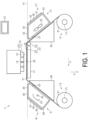
FIG. 1 is a side view illustrating an example of a printing apparatus. -
FIG. 2 is a side view of a state where printing is performed on a rigid medium. -
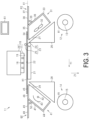
FIG. 3 is a side view of a state where a heating extension portion is located at a heating extension position and an air blowing extension portion is located at an air blowing extension position. -
FIG. 4 is a side view illustrating a modification of the printing apparatus. - An example of a printing apparatus is described below with reference to the drawings. The printing apparatus is an ink-jet printer that records images such as letters, photographs and diagrams by ejecting ink as an example of liquid to a medium such as fabric and a sheet, for example. The printing apparatus performs printing on a soft medium and a rigid medium as the medium.
- As illustrated in
FIGS. 1 and2 , aprinting apparatus 11 includes afeeding part 12. Thefeeding part 12 is configured to feed a soft medium S1 with flexibility. Thefeeding part 12 feeds the unused soft medium S1. - The soft medium S1 is a medium such as fabric and thin paper. Therefore, the soft medium S1 can be bent and curved during conveyance. The soft medium S1 is fed from a roll R1 obtained by winding the soft medium S1, for example.
- The
feeding part 12 includes afeeding shaft 13. Thefeeding shaft 13 holds the unused roll R1. When the roll R1 held by thefeeding shaft 13 rotates, the unused soft medium S1 is fed from thefeeding part 12. Images are printed on the soft medium S1 fed from thefeeding part 12. - The
printing apparatus 11 includes awinding unit 14. Thewinding unit 14 is configured to wind up the soft medium S1. Specifically, thewinding unit 14 winds up the soft medium S1 fed from thefeeding part 12. Thewinding unit 14 winds up the used soft medium S1. That is, an image is printed on the soft medium S1 in the process from the feeding of the soft medium S1 by thefeeding part 12 to the winding of the soft medium S1 by thewinding unit 14. - The
winding unit 14 includes awinding shaft 15. The windingshaft 15 holds the used roll R1. When the roll R1 held by thewinding shaft 15 rotates, the used soft medium S1 is wound around thewinding unit 14. - The
printing apparatus 11 includes aprinting unit 16. Theprinting unit 16 is configured to print an image on a medium by ejecting liquid. Theprinting unit 16 prints an image on the soft medium S1, for example. Theprinting unit 16 may perform printing not only on the soft medium S1, but also on a rigid medium H1. The rigid medium H1 is thick paper, board paper and the like. The rigid medium H1 is not bent or curved during conveyance. Therefore, the rigid medium H1 is not fed from thefeeding part 12, or wound by thewinding unit 14. The rigid medium H1 is separately supplied to theprinting unit 16 separately from the soft medium S1. - The
printing unit 16 includes ahead 17. Thehead 17 includes anozzle surface 19 at which one ormore nozzles 18 open. Thehead 17 ejects liquid from thenozzle 18. - The
printing unit 16 includes acarriage 20. Thecarriage 20 is equipped with thehead 17. Thecarriage 20 performs scanning with respect to the medium. Through the scanning of thecarriage 20, thehead 17 can eject the liquid over the entire width of the medium. As described above, theprinting apparatus 11 is a so-called serial printer. Theprinting apparatus 11 may be a line printer of which thehead 17 can eject liquid at the same time over the width of the medium. - The
printing apparatus 11 includes a supportingpart 21. The supportingpart 21 supports a medium. Specifically, the supportingpart 21 supports the medium being conveyed. The supportingpart 21 supports the medium from below. The supportingpart 21 faces theprinting unit 16. Thus, liquid is ejected from theprinting unit 16 to the medium in the region supported by the supportingpart 21. - The supporting
part 21 includes a supportingsurface 22 that supports the medium. The supportingsurface 22 is a surface that faces theprinting unit 16. Specifically, the supportingsurface 22 faces thenozzle surface 19. The supportingsurface 22 makes contact with the medium. The supportingsurface 22 faces upward, for example. The position of the supportingsurface 22 in a vertical direction Z1 is a reference position A1. That is, the reference position A1 represents the height of the supportingsurface 22. - The supporting
part 21 is located on the upper side of the feedingpart 12. The supportingpart 21 is located on the upper side of the windingunit 14. Thus, the soft medium S1 extending from the feedingpart 12 to the windingunit 14 is provided across the supportingpart 21. - The
printing apparatus 11 includes aconveyance unit 23. Theconveyance unit 23 is configured to convey a medium. Theconveyance unit 23 conveys the medium in a conveyance direction Y1 on the supportingsurface 22. Therefore, the conveyance direction Y1 is a direction along the supportingsurface 22. Theconveyance unit 23 conveys the soft medium S1 in the conveyance direction Y1 on the supportingsurface 22. Theconveyance unit 23 conveys the rigid medium H1 in the conveyance direction Y1 on the supportingsurface 22. As an example, theconveyance unit 23 is located upstream of the supportingpart 21 in the conveyance direction Y1. Theconveyance unit 23 may be located downstream of the supportingpart 21 in the conveyance direction Y1. - The
conveyance unit 23 includes afirst roller 24 and asecond roller 25. Thefirst roller 24 and thesecond roller 25 convey the medium by rotating with the medium sandwiched therebetween. The nip point of thefirst roller 24 and thesecond roller 25 is at the same height as the reference position A1. Thus, thefirst roller 24 and thesecond roller 25 sandwich the medium at the reference position A1. - The
first roller 24 and thesecond roller 25 sandwich the medium, and thus the medium is set in theprinting apparatus 11. The soft medium S1 is set in theprinting apparatus 11 by being provided across the supportingpart 21 from the feedingpart 12 to the windingunit 14. The rigid medium H1 is set in theprinting apparatus 11 by being inserted between thefirst roller 24 and thesecond roller 25. At this time, the rigid medium H1 is set so as to protrude to the upstream side in the conveyance direction Y1 from the location on the supportingpart 21. - The
printing apparatus 11 includes an upstream supportingpart 26. Theupstream supporting part 26 is located upstream of the supportingpart 21 in the conveyance direction Y1. Theupstream supporting part 26 is located at a position below the reference position A1. Theupstream supporting part 26 supports the soft medium S1. Specifically, theupstream supporting part 26 supports the soft medium S1 in the period from the feeding from the feedingpart 12 to the sandwiching by thefirst roller 24 and thesecond roller 25. On the other hand, theupstream supporting part 26 does not support the rigid medium H1. - The
upstream supporting part 26 includes an upstream supportingsurface 27 that supports the soft medium S1. Theupstream supporting surface 27 is a surface that obliquely extends with respect to the supportingsurface 22. As an example, theupstream supporting surface 27 is a surface that tilts obliquely upward in the direction from the feedingpart 12 toward the supportingpart 21. - The
printing apparatus 11 includes a downstream supportingpart 28. The downstream supportingpart 28 is located downstream of the supportingpart 21 in the conveyance direction Y1. The downstream supportingpart 28 is located at a position below the reference position A1. The downstream supportingpart 28 supports the soft medium S1. Specifically, the downstream supportingpart 28 supports the soft medium S1 in the period until it is wound by the windingunit 14 after being supported by the supportingpart 21. On the other hand, the downstream supportingpart 28 does not support the rigid medium H1. - The downstream supporting
part 28 includes a downstream supportingsurface 29 that supports the soft medium S1. The downstream supportingsurface 29 is a surface that obliquely extends with respect to the supportingsurface 22. As an example, the downstream supportingsurface 29 is a surface that tilts obliquely downward in the direction from the supportingpart 21 toward the windingunit 14. - The
printing apparatus 11 may include anair blowing unit 31. Theair blowing unit 31 faces theupstream supporting part 26. Specifically, theair blowing unit 31 faces theupstream supporting surface 27. Theair blowing unit 31 is configured to blow air to the soft medium S1. Theair blowing unit 31 removes foreign matters from the soft medium S1 by blowing air to the soft medium S1. Specifically, theair blowing unit 31 removes foreign matters from the soft medium S1 before the printing. In this manner, the printing quality of the soft medium S1 is improved. - The
air blowing unit 31 includes anair blowing part 32. Theair blowing part 32 blows air to the soft medium S1 supported by theupstream supporting part 26. Specifically, theair blowing part 32 blows air to the soft medium S1 in the portion located on theupstream supporting surface 27. Theair blowing part 32 is a fan, for example. - The
air blowing unit 31 includes anair blowing case 33. Theair blowing case 33 houses theair blowing part 32. Theair blowing case 33 opens toward theupstream supporting part 26. - The
air blowing case 33 includes an air blowingtop portion 34. The air blowingtop portion 34 is a portion located at the uppermost position in theair blowing case 33. The air blowingtop portion 34 is located at a position below the reference position A1. That is, theair blowing unit 31 is not located above the supportingsurface 22. As a result, when setting the rigid medium H1, theair blowing unit 31 does not interfere with the rigid medium H1. Thus, the rigid medium H1 is set in the state where it extends straight to the upstream side in the conveyance direction Y1 from the location on the supportingpart 21. In this manner, theprinting apparatus 11 can perform printing on the rigid medium H1 without detaching theair blowing unit 31. In addition, since it is not necessary to detach theair blowing unit 31, it is not necessary to ensure the housing space for the detachedair blowing unit 31. - The air blowing
top portion 34 is located at the reference position A1. That is, the air blowingtop portion 34 is located at the same height as the supportingsurface 22. As a result, when setting the rigid medium H1, the air blowingtop portion 34 can support the rigid medium H1 together with the supportingpart 21. With the air blowingtop portion 34 supporting the rigid medium H1, the posture of the rigid medium H1 is stabilized. - The air blowing
top portion 34 may include an air blowingtop surface 35. The air blowingtop surface 35 is the outer surface of theair blowing case 33. As an example, the air blowingtop surface 35 is a surface facing upward in theair blowing case 33. The air blowingtop surface 35 is located at the reference position A1. That is, the air blowingtop surface 35 is located at the same height as the supportingsurface 22. The air blowingtop surface 35 supports the rigid medium H1. In this manner, the posture of the rigid medium H1 is easily stabilized. - The
air blowing case 33 may include an air blowingcontinuous surface 36 that is continuous with the air blowingtop surface 35. As an example, the air blowingcontinuous surface 36 extends obliquely downward from the air blowingtop surface 35. Specifically, the air blowingcontinuous surface 36 extends parallel to theupstream supporting surface 27. - As illustrated in
FIG. 3 , theair blowing case 33 includes an airblowing extension portion 37. The airblowing extension portion 37 is a portion extending the air blowingtop portion 34. The airblowing extension portion 37 includes an airblowing extension surface 38. The airblowing extension surface 38 is a surface extending the air blowingtop surface 35. The airblowing extension surface 38 extends parallel to the air blowingtop surface 35. The airblowing extension surface 38 is continuous with the air blowingtop surface 35. The airblowing extension surface 38 is located at the reference position A1 as with the air blowingtop surface 35. With the airblowing extension portion 37 extending the air blowingtop portion 34, the air blowingtop surface 35 and the air blowingextension surface 38 support the rigid medium H1. In this manner, the posture of the rigid medium H1 is easily stabilized. - As illustrated in
FIGS. 2 and3 , the airblowing extension portion 37 is configured to be displaced to an air blowing housing position P1 and an air blowing extension position P2. As an example, the airblowing extension portion 37 is displaced by rotating. For example, the airblowing extension portion 37 is displaced by rotating around one end portion. The airblowing extension portion 37 rotates with ahinge 39. The airblowing extension portion 37 may be displaced not only by rotating but also by sliding, for example. - The air blowing housing position P1 is a position where the air
blowing extension portion 37 is housed in theair blowing case 33. As an example, the air blowing housing position P1 is a position where the airblowing extension portion 37 is set along the air blowingcontinuous surface 36. The airblowing extension portion 37 illustrated inFIG. 2 is located at the air blowing housing position P1. - The air blowing extension position P2 is a position where the air
blowing extension portion 37 extends the air blowingtop portion 34. As an example, the air blowing extension position P2 is a position where the air blowingextension surface 38 is continuous with the air blowingtop surface 35. The airblowing extension portion 37 illustrated inFIG. 3 is located at the air blowing extension position P2. - As illustrated in
FIGS. 1 and2 , theprinting apparatus 11 may include aheating unit 41. Theheating unit 41 faces the downstream supportingpart 28. Specifically, theheating unit 41 faces the downstream supportingsurface 29. Thus, theheating unit 41 is configured to heat the soft medium S1. Theheating unit 41 dries the soft medium S1 by heating the soft medium S1. That is, theheating unit 41 dries the soft medium S1 after the printing. In this manner, the printing quality of the soft medium S1 is improved. - The
heating unit 41 includes aheating part 42. Theheating part 42 heats the soft medium S1 supported by the downstream supportingpart 28. Specifically, theheating part 42 heats the portion located on the downstream supportingsurface 29 in the soft medium S1. Theheating part 42 is an infrared ray heater, for example. - The
heating unit 41 may include areflection plate 43. Thereflection plate 43 reflects, toward the downstream supportingsurface 29, the infrared ray emitted from theheating part 42. In this manner, the heating efficiency of theheating part 42 is improved. - The
heating unit 41 includes aheating case 44. Theheating case 44 houses theheating part 42. Theheating case 44 houses thereflection plate 43. Theheating case 44 opens toward the downstream supportingpart 28. - The
heating case 44 includes aheating top portion 45. Theheating top portion 45 is a portion located at the uppermost position in theheating case 44. Theheating top portion 45 is located at a position below the reference position A1. That is, theheating unit 41 is not located above the supportingsurface 22. Thus, when ejecting the rigid medium H1, theheating unit 41 does not interfere with the rigid medium H1. In this manner, theprinting apparatus 11 can perform printing on the rigid medium H1 without detaching theheating unit 41. In addition, since it is not necessary to detach theheating unit 41, it is not necessary to ensure a housing space for thedetached heating unit 41. - The
heating top portion 45 is located at the reference position A1. That is, theheating top portion 45 is located at the same height as the supportingsurface 22. In this manner, when ejecting the rigid medium H1, theheating top portion 45 can support the rigid medium H1 together with the supportingpart 21. Thus, the posture of the rigid medium H1 is stabilized. - The
heating top portion 45 may include aheating top surface 46. Theheating top surface 46 is an outer surface of theheating case 44. As an example, theheating top surface 46 is a surface facing upward in theheating case 44. Theheating top surface 46 is located at the reference position A1. That is, theheating top surface 46 is located at the same height as the supportingsurface 22. Theheating top surface 46 supports the rigid medium H1. In this manner, the posture of the rigid medium H1 is easily stabilized. - The
heating case 44 may include a heatingcontinuous surface 47 that is continuous with theheating top surface 46. As an example, the heatingcontinuous surface 47 extends obliquely downward from theheating top surface 46. Specifically, the heatingcontinuous surface 47 extends parallel to the downstream supportingsurface 29. - As illustrated in
FIG. 3 , theheating case 44 includes aheating extension portion 48. Theheating extension portion 48 is a portion extending theheating top portion 45. Theheating extension portion 48 includes aheating extension surface 49. Theheating extension surface 49 is a surface extending theheating top surface 46. Theheating extension surface 49 extends parallel to theheating top surface 46. Theheating extension surface 49 is continuous with theheating top surface 46. Theheating extension surface 49 is located at the reference position A1 as with theheating top surface 46. With theheating extension portion 48 extending theheating top portion 45, theheating top surface 46 and theheating extension surface 49 support the rigid medium H1. In this manner, the posture of the rigid medium H1 is easily stabilized. - As illustrated in
FIGS. 2 and3 , theheating extension portion 48 is configured to be displaced to a heating housing position Q1 and a heating extension position Q2. As an example, theheating extension portion 48 is displaced by rotating. For example, theheating extension portion 48 is displaced by rotating around one end portion. Theheating extension portion 48 rotates with ahinge 50. Theheating extension portion 48 may be displaced not only by rotating but also by sliding, for example. - The heating housing position Q1 is a position where the
heating extension portion 48 is housed in theheating case 44. As an example, the heating housing position Q1 is a position where theheating extension portion 48 is set along the heatingcontinuous surface 47. Theheating extension portion 48 illustrated inFIG. 2 is located at the heating housing position Q1. - The heating extension position Q2 is a position where the
heating extension portion 48 extends theheating top portion 45. As an example, the heating extension position Q2 is a position where theheating extension surface 49 is continuous with theheating top surface 46. Theheating extension portion 48 illustrated inFIG. 3 is located at the heating extension position Q2. - The
printing apparatus 11 may include anoperation unit 61. Theoperation unit 61 is a touch panel, for example. Theoperation unit 61 may be a button, a lever, a switch, and the like. When theoperation unit 61 is operated, printing is started. That is, when theoperation unit 61 is operated, the driving of theprinting unit 16, theconveyance unit 23 and the like is started. - The user may select whether printing is performed on the soft medium S1 or the rigid medium H1 from the
operation unit 61. In the case where printing on the soft medium S1 is started through the operation of theoperation unit 61, the driving of the feedingpart 12, the windingunit 14, theair blowing unit 31, theheating unit 41 and the like is also started. In the case where printing on the rigid medium H1 is started through the operation of theoperation unit 61, the airblowing extension portion 37 and theheating extension portion 48 may be displaced. Specifically, the airblowing extension portion 37 may be displaced to the air blowing extension position P2 and theheating extension portion 48 may be displaced to the heating extension position Q2. In this case, the supportingsurface 22, the air blowingextension surface 38, and theheating extension surface 49 are located at the reference position A1 and arranged on a straight line. In this manner, the rigid medium H1 is conveyed in a stable posture. - After printing on the rigid medium H1 is completed, the air
blowing extension portion 37 may be displaced to the air blowing housing position P1 and theheating extension portion 48 may be displaced to the heating housing position Q1. In this manner, the airblowing extension portion 37 and theheating extension portion 48 are prevented from hindering the operation. In addition, regardless of the start and termination of the printing, the airblowing extension portion 37 and theheating extension portion 48 may be displaced when theoperation unit 61 is operated. In addition, the user may manually displace the airblowing extension portion 37 and theheating extension portion 48 without using theoperation unit 61. - Next, operational effects of the above-mentioned embodiment are described.
- (1) The
heating top portion 45 is located at a position below the supportingsurface 22. With the above-mentioned configuration, when the medium is conveyed straight along the supportingsurface 22, i.e., when the rigid medium H1 is conveyed, the rigid medium H1 does not interfere with theheating unit 41. Therefore, even when printing is performed on the rigid medium H1, it is not necessary to detach theheating unit 41. Thus, the reduction in usability is suppressed. - (2) The
heating top portion 45 is located at the same height as the supportingsurface 22. With the above-mentioned configuration, when the medium is conveyed straight along the supportingsurface 22, i.e., when the rigid medium H1 is conveyed, theheating top portion 45 can support the rigid medium H1. With theheating top portion 45 supporting the rigid medium H1, the posture of the rigid medium H1 is stabilized. - (3) The
heating top portion 45 includes theheating top surface 46 located at the same height as the supportingsurface 22. With the above-mentioned configuration, when the medium is conveyed straight along the supportingsurface 22, i.e., when the rigid medium H1 is conveyed, theheating top surface 46 can support the rigid medium H1. Thus, in comparison with the case where theheating top portion 45 supports the rigid medium H1 in a small area, the posture of the rigid medium H1 is stabilized. - (4) The
heating extension portion 48 is configured to be displaced to the heating extension position Q2 where it extends theheating top portion 45 and the heating housing position Q1 where it is housed in theheating case 44. With the above-mentioned configuration, when theheating extension portion 48 is located at the heating extension position Q2, theheating top portion 45 and theheating extension portion 48 can support the rigid medium H1 when the medium is conveyed straight along the supportingsurface 22, i.e., when the rigid medium H1 is conveyed. When theheating extension portion 48 is located at the heating housing position Q1, theheating extension portion 48 is prevented from hindering the operation when the soft medium S1 is conveyed from the supportingpart 21 to the downstream supportingpart 28. - (5) The air blowing
top portion 34 is located at a position below the supportingsurface 22. With the above-mentioned configuration, when the medium is conveyed straight along the supportingsurface 22, i.e., when the rigid medium H1 is conveyed, the rigid medium H1 does not interfere with theair blowing unit 31. Therefore, even when printing is performed on the rigid medium H1, it is not necessary to detach theair blowing unit 31. Thus, the reduction in usability is suppressed. - (6) The air blowing
top portion 34 is located at the same height as the supportingsurface 22. With the above-mentioned configuration, when the medium is conveyed straight along the supportingsurface 22, i.e., when the rigid medium H1 is conveyed, the air blowingtop portion 34 can support the rigid medium H1. With the air blowingtop portion 34 supporting the rigid medium H1, the posture of the rigid medium H1 is stabilized. - (7) The air blowing
top portion 34 includes the air blowingtop surface 35 located at the same height as the supportingsurface 22. With the above-mentioned configuration, when the medium is conveyed straight along the supportingsurface 22, i.e., when the rigid medium H1 is conveyed, the air blowingtop surface 35 can support the rigid medium H1. Thus, in comparison with the case where the air blowingtop portion 34 supports the rigid medium H1 in a small area, the posture of the rigid medium H1 is stabilized. - (8) The air
blowing extension portion 37 is configured to be displaced to the air blowing extension position P2 where it extends the air blowingtop portion 34, and the air blowing housing position P1 where it is housed in theair blowing case 33. With the above-mentioned configuration, when the airblowing extension portion 37 is located at the air blowing extension position P2, the air blowingtop portion 34 and the airblowing extension portion 37 can support the rigid medium H1 when the medium is conveyed straight along the supportingsurface 22, i.e., when the rigid medium H1 is conveyed. When the airblowing extension portion 37 is located at the air blowing housing position P1, the airblowing extension portion 37 is prevented from hindering the operation when the soft medium S1 is conveyed from the supportingpart 21 to the downstream supportingpart 28. - The above-mentioned example may be modified as follows for implementation. The above-mentioned examples and the following modifications may be combined for implementation insofar as they are not technically inconsistent.
- As illustrated in
FIG. 4 , the air blowingextension surface 38 may also serve as the air blowingcontinuous surface 36. Specifically, the airblowing extension portion 37 may make up the exterior of theair blowing case 33. In this modification, the airblowing extension portion 37 exposes the inside of theair blowing case 33 when it is located at the air blowing extension position P2. When printing is performed on the rigid medium H1, theair blowing unit 31 is not used. Therefore, no problem occurs even when the inside of the air blowing case 33is exposed. When the airblowing extension portion 37 is located at the air blowing housing position P1, theair blowing part 32 is covered by theair blowing case 33. - As illustrated in
FIG. 4 , theheating extension surface 49 may also serve as the heatingcontinuous surface 47. Specifically, theheating extension portion 48 may make up the exterior of theheating case 44. In this modification, theheating extension portion 48 exposes theheating case 44 when it is located at the heating extension position Q2. When printing is performed on the rigid medium H1, theheating unit 41 is not used. Therefore, no problem occurs even when theheating case 44 is exposed. When theheating extension portion 48 is located at the heating housing position Q1, theheating part 42 is covered by theheating case 44. - The liquid ejected by the
head 17 is not limited to ink, but may be a liquid member obtained by dispersing or mixing particles of a functional material in liquid. For example, thehead 17 may eject a liquid member obtained by dispersing or dissolving a material such as an electrode material or a pixel material used for the manufacture of liquid crystal displays, electroluminescence displays, surface-emitting displays and the like. - The following describes technical ideas and operational effects thereof derived from the above-described examples and modifications.
- (A) A printing apparatus includes a printing unit configured to perform printing by ejecting liquid to a medium conveyed, a supporting part facing the printing unit, and including a supporting surface configured to support the medium, a downstream supporting part located downstream of the supporting part in a medium conveyance direction, and including a downstream supporting surface obliquely extending with respect to the supporting surface, and a heating unit facing the downstream supporting part. The heating unit includes: a heating part configured to heat the medium, and a heating case configured to house the heating part, the heating case includes a heating top portion located at an uppermost position in the heating case, and the heating top portion is located at a position below the supporting surface. With the above-mentioned configuration, when the medium is conveyed straight along the supporting surface, the medium does not interfere with the heating unit. Therefore, even when the printing is performed on a rigid medium, it is not necessary to detach the heating unit. Thus, the reduction in usability is suppressed.
- (B) In the printing apparatus, the heating top portion is located at the same height as the supporting surface. With the above-mentioned configuration, when the medium is conveyed straight along the supporting surface, the heating top portion can support the medium. With the heating top portion supporting the medium, the posture of the medium is stabilized.
- (C) In the printing apparatus, the heating top portion includes a heating top surface located at the same height as the supporting surface. With the above-mentioned configuration, when the medium is conveyed straight along the supporting surface, the heating top surface supports the medium. In comparison with the case where the heating top part supports the medium in a small area, the posture of the medium is stabilized.
- (D) In the printing apparatus, the heating case includes a heating extension portion extending the heating top portion, and the heating extension portion is configured to be displaced to a heating extension position where the heating extension portion extends the heating top portion, and a heating housing position where the heating extension portion is housed in the heating case. With the above-mentioned configuration, when the heating extension portion is located at the heating extension position, the heating top portion and the heating extension portion can support the medium when the medium is conveyed straight along the supporting surface. When the heating extension portion is located at the heating housing position, the heating extension portion is prevented from hindering the operation when the medium is conveyed from the supporting part to the downstream supporting part.
- (E) The printing apparatus further includes an upstream supporting part located upstream of the supporting part in the conveyance direction, and including an upstream supporting surface obliquely extending with respect to the supporting surface, and an air blowing unit facing the upstream supporting part. The air blowing unit includes: an air blowing part configured to blow air to the medium, and an air blowing case configured to house the air blowing part, the air blowing case includes an air blowing top portion located at an uppermost position in the air blowing case, and the air blowing top portion is located at a position below the supporting surface. With the above-mentioned configuration, when the medium is conveyed straight along the supporting surface, the medium does not interfere with the air blowing unit. Therefore, even when the printing is performed on a rigid medium, it is not necessary to detach the air blowing unit. Thus, the reduction in usability is suppressed.
- (F) In the printing apparatus, the air blowing top portion is located at the same height as the supporting surface. With the above-mentioned configuration, when the medium is conveyed straight along the supporting surface, the air blowing top portion can support the medium. With the air blowing top portion supporting the medium, the posture of the medium is stabilized.
- (G) In the printing apparatus, the air blowing top portion includes an air blowing top surface located at the same height as the supporting surface. With the above-mentioned configuration, when the medium is conveyed straight along the supporting surface, the air blowing top surface supports the medium. In comparison with the case where the air blowing top part supports the medium in a small area, the posture of the medium is stabilized.
- (H) In the printing apparatus, the air blowing case includes an air blowing extension portion extending the air blowing top portion, and the air blowing extension portion is configured to be displaced to an air blowing extension position where the air blowing extension portion extends the air blowing top portion, and an air blowing housing position where the air blowing extension portion is housed in the air blowing case. With the above-mentioned configuration, when the air blowing extension portion is located at the air blowing extension position, the air blowing top portion and the air blowing extension portion can support the medium when the medium is conveyed straight along the supporting surface. When the air blowing extension portion is located at the air blowing housing position, the air blowing extension portion is prevented from hindering the operation when the medium is conveyed from the supporting part to the downstream supporting part.
- (I) A printing apparatus includes a printing unit configured to perform printing by ejecting liquid to a medium conveyed, a supporting part facing the printing unit, and including a supporting surface configured to support the medium, an upstream supporting part located upstream of the supporting part in a medium conveyance direction, and including an upstream supporting surface obliquely extending with respect to the supporting surface, an air blowing unit facing the upstream supporting part. The air blowing unit includes: an air blowing part configured to blow air toward the upstream supporting surface, and an air blowing case configured to house the air blowing part, the air blowing case includes an air blowing top portion located at an uppermost position in the air blowing case, and the air blowing top portion is located at a position below the supporting surface. With the above-mentioned configuration, when the medium is conveyed straight along the supporting surface, the medium does not interfere with the air blowing unit. Therefore, even when the printing is performed on a rigid medium, it is not necessary to detach the air blowing unit. Thus, the reduction in usability is suppressed.
Claims (9)
- A printing apparatus comprising:a printing unit configured to perform printing by ejecting liquid to a medium conveyed;a supporting part facing the printing unit, and including a supporting surface configured to support the medium;a downstream supporting part located downstream of the supporting part in a medium conveyance direction, and including a downstream supporting surface obliquely extending with respect to the supporting surface; anda heating unit facing the downstream supporting part, whereinthe heating unit includes:a heating part configured to heat the medium, anda heating case configured to house the heating part,the heating case includes a heating top portion located at an uppermost position in the heating case, andthe heating top portion is located at a position below the supporting surface.
- The printing apparatus according to claim 1, wherein the heating top portion is located at the same height as the supporting surface.
- The printing apparatus according to claim 2, wherein the heating top portion includes a heating top surface located at the same height as the supporting surface.
- The printing apparatus according to claim 3, whereinthe heating case includes a heating extension portion extending the heating top portion, andthe heating extension portion is configured to be displaced to a heating extension position where the heating extension portion extends the heating top portion, and a heating housing position where the heating extension portion is housed in the heating case.
- The printing apparatus according to claim 1, further comprising:an upstream supporting part located upstream of the supporting part in the conveyance direction, and including an upstream supporting surface obliquely extending with respect to the supporting surface; andan air blowing unit facing the upstream supporting part, whereinthe air blowing unit includes:an air blowing part configured to blow air to the medium, andan air blowing case configured to house the air blowing part,the air blowing case includes an air blowing top portion located at an uppermost position in the air blowing case, andthe air blowing top portion is located at a position below the supporting surface.
- The printing apparatus according to claim 5, wherein the air blowing top portion is located at the same height as the supporting surface.
- The printing apparatus according to claim 6, wherein the air blowing top portion includes an air blowing top surface located at the same height as the supporting surface.
- The printing apparatus according to claim 7, whereinthe air blowing case includes an air blowing extension portion extending the air blowing top portion, andthe air blowing extension portion is configured to be displaced to an air blowing extension position where the air blowing extension portion extends the air blowing top portion, and an air blowing housing position where the air blowing extension portion is housed in the air blowing case.
- A printing apparatus comprising:a printing unit configured to perform printing by ejecting liquid to a medium conveyed;a supporting part facing the printing unit, and including a supporting surface configured to support the medium;an upstream supporting part located upstream of the supporting part in a medium conveyance direction, and including an upstream supporting surface obliquely extending with respect to the supporting surface,an air blowing unit facing the upstream supporting part, whereinthe air blowing unit includes:an air blowing part configured to blow air toward the upstream supporting surface, andan air blowing case configured to house the air blowing part,the air blowing case includes an air blowing top portion located at an uppermost position in the air blowing case, andthe air blowing top portion is located at a position below the supporting surface.
Applications Claiming Priority (1)
| Application Number | Priority Date | Filing Date | Title |
|---|---|---|---|
| JP2022202192A JP2024087391A (en) | 2022-12-19 | 2022-12-19 | Printing device |
Publications (3)
| Publication Number | Publication Date |
|---|---|
| EP4389435A2 true EP4389435A2 (en) | 2024-06-26 |
| EP4389435A3 EP4389435A3 (en) | 2024-07-03 |
| EP4389435B1 EP4389435B1 (en) | 2025-07-16 |
Family
ID=89223820
Family Applications (1)
| Application Number | Title | Priority Date | Filing Date |
|---|---|---|---|
| EP23217623.0A Active EP4389435B1 (en) | 2022-12-19 | 2023-12-18 | Printing apparatus |
Country Status (3)
| Country | Link |
|---|---|
| EP (1) | EP4389435B1 (en) |
| JP (1) | JP2024087391A (en) |
| CN (1) | CN118219672A (en) |
Citations (1)
| Publication number | Priority date | Publication date | Assignee | Title |
|---|---|---|---|---|
| JP2020104320A (en) | 2018-12-26 | 2020-07-09 | セイコーエプソン株式会社 | Dryer and printer |
Family Cites Families (3)
| Publication number | Priority date | Publication date | Assignee | Title |
|---|---|---|---|---|
| US6988797B2 (en) * | 2003-03-12 | 2006-01-24 | Hewlett-Packard Development Company, L.P. | Unbacked fabric transport and condition system |
| JP6531423B2 (en) * | 2015-02-24 | 2019-06-19 | セイコーエプソン株式会社 | Printing device |
| JP6790505B2 (en) * | 2016-06-29 | 2020-11-25 | セイコーエプソン株式会社 | Printing equipment |
-
2022
- 2022-12-19 JP JP2022202192A patent/JP2024087391A/en active Pending
-
2023
- 2023-12-14 CN CN202311722995.8A patent/CN118219672A/en active Pending
- 2023-12-18 EP EP23217623.0A patent/EP4389435B1/en active Active
Patent Citations (1)
| Publication number | Priority date | Publication date | Assignee | Title |
|---|---|---|---|---|
| JP2020104320A (en) | 2018-12-26 | 2020-07-09 | セイコーエプソン株式会社 | Dryer and printer |
Also Published As
| Publication number | Publication date |
|---|---|
| EP4389435A3 (en) | 2024-07-03 |
| CN118219672A (en) | 2024-06-21 |
| EP4389435B1 (en) | 2025-07-16 |
| JP2024087391A (en) | 2024-07-01 |
Similar Documents
| Publication | Publication Date | Title |
|---|---|---|
| CN108454233B (en) | Ink jet printing apparatus | |
| JP4084511B2 (en) | Printer | |
| JP2016511166A (en) | Printing device for printing on a printed circuit board | |
| JP3935310B2 (en) | Internal paper guide for printer media shape control | |
| EP4389435B1 (en) | Printing apparatus | |
| JPH1058661A (en) | Ink jet printer | |
| US6231176B1 (en) | Self-tensioning flexible heater assembly for drying image bearing substrates in an ink jet printer | |
| JP7469954B2 (en) | Recording device | |
| CN115923348A (en) | Printing device and printing method | |
| JP2024098419A (en) | Printing device | |
| JP2020059221A (en) | Printer and control method for printer | |
| JP2023095336A (en) | Sheet feeding device and recording device | |
| JP7617711B2 (en) | Recording device and control method | |
| JP2021074964A (en) | Printer | |
| US20260054506A1 (en) | Recording apparatus | |
| US11607895B2 (en) | Printing apparatus including a detachable star wheel | |
| CN115923347A (en) | Printing device and printing method | |
| JPH07132659A (en) | Sheet delivering device for printer | |
| US20110058002A1 (en) | Printing method | |
| JP2002205854A (en) | Recording device | |
| JP2004155027A (en) | Recording device | |
| JP2004268271A (en) | Recording medium cassette | |
| JPH06305126A (en) | Ink jet printing apparatus | |
| JP2002283557A (en) | Recording device | |
| CN118544690A (en) | Printing apparatus |
Legal Events
| Date | Code | Title | Description |
|---|---|---|---|
| PUAI | Public reference made under article 153(3) epc to a published international application that has entered the european phase |
Free format text: ORIGINAL CODE: 0009012 |
|
| STAA | Information on the status of an ep patent application or granted ep patent |
Free format text: STATUS: THE APPLICATION HAS BEEN PUBLISHED |
|
| PUAL | Search report despatched |
Free format text: ORIGINAL CODE: 0009013 |
|
| AK | Designated contracting states |
Kind code of ref document: A2 Designated state(s): AL AT BE BG CH CY CZ DE DK EE ES FI FR GB GR HR HU IE IS IT LI LT LU LV MC ME MK MT NL NO PL PT RO RS SE SI SK SM TR |
|
| AK | Designated contracting states |
Kind code of ref document: A3 Designated state(s): AL AT BE BG CH CY CZ DE DK EE ES FI FR GB GR HR HU IE IS IT LI LT LU LV MC ME MK MT NL NO PL PT RO RS SE SI SK SM TR |
|
| RIC1 | Information provided on ipc code assigned before grant |
Ipc: B41J 3/407 20060101ALN20240524BHEP Ipc: B41J 11/00 20060101AFI20240524BHEP |
|
| STAA | Information on the status of an ep patent application or granted ep patent |
Free format text: STATUS: REQUEST FOR EXAMINATION WAS MADE |
|
| 17P | Request for examination filed |
Effective date: 20240919 |
|
| RBV | Designated contracting states (corrected) |
Designated state(s): AL AT BE BG CH CY CZ DE DK EE ES FI FR GB GR HR HU IE IS IT LI LT LU LV MC ME MK MT NL NO PL PT RO RS SE SI SK SM TR |
|
| GRAP | Despatch of communication of intention to grant a patent |
Free format text: ORIGINAL CODE: EPIDOSNIGR1 |
|
| STAA | Information on the status of an ep patent application or granted ep patent |
Free format text: STATUS: GRANT OF PATENT IS INTENDED |
|
| INTG | Intention to grant announced |
Effective date: 20250317 |
|
| GRAS | Grant fee paid |
Free format text: ORIGINAL CODE: EPIDOSNIGR3 |
|
| GRAA | (expected) grant |
Free format text: ORIGINAL CODE: 0009210 |
|
| STAA | Information on the status of an ep patent application or granted ep patent |
Free format text: STATUS: THE PATENT HAS BEEN GRANTED |
|
| AK | Designated contracting states |
Kind code of ref document: B1 Designated state(s): AL AT BE BG CH CY CZ DE DK EE ES FI FR GB GR HR HU IE IS IT LI LT LU LV MC ME MK MT NL NO PL PT RO RS SE SI SK SM TR |
|
| REG | Reference to a national code |
Ref country code: GB Ref legal event code: FG4D |
|
| REG | Reference to a national code |
Ref country code: CH Ref legal event code: EP Ref country code: DE Ref legal event code: R096 Ref document number: 602023004881 Country of ref document: DE |
|
| REG | Reference to a national code |
Ref country code: IE Ref legal event code: FG4D |
|
| REG | Reference to a national code |
Ref country code: NL Ref legal event code: MP Effective date: 20250716 |
|
| PG25 | Lapsed in a contracting state [announced via postgrant information from national office to epo] |
Ref country code: PT Free format text: LAPSE BECAUSE OF FAILURE TO SUBMIT A TRANSLATION OF THE DESCRIPTION OR TO PAY THE FEE WITHIN THE PRESCRIBED TIME-LIMIT Effective date: 20251117 |
|
| PG25 | Lapsed in a contracting state [announced via postgrant information from national office to epo] |
Ref country code: NL Free format text: LAPSE BECAUSE OF FAILURE TO SUBMIT A TRANSLATION OF THE DESCRIPTION OR TO PAY THE FEE WITHIN THE PRESCRIBED TIME-LIMIT Effective date: 20250716 |
|
| REG | Reference to a national code |
Ref country code: AT Ref legal event code: MK05 Ref document number: 1813714 Country of ref document: AT Kind code of ref document: T Effective date: 20250716 |
|
| PG25 | Lapsed in a contracting state [announced via postgrant information from national office to epo] |
Ref country code: IS Free format text: LAPSE BECAUSE OF FAILURE TO SUBMIT A TRANSLATION OF THE DESCRIPTION OR TO PAY THE FEE WITHIN THE PRESCRIBED TIME-LIMIT Effective date: 20251116 |
|
| PG25 | Lapsed in a contracting state [announced via postgrant information from national office to epo] |
Ref country code: NO Free format text: LAPSE BECAUSE OF FAILURE TO SUBMIT A TRANSLATION OF THE DESCRIPTION OR TO PAY THE FEE WITHIN THE PRESCRIBED TIME-LIMIT Effective date: 20251016 |
|
| REG | Reference to a national code |
Ref country code: LT Ref legal event code: MG9D |
|
| PG25 | Lapsed in a contracting state [announced via postgrant information from national office to epo] |
Ref country code: AT Free format text: LAPSE BECAUSE OF FAILURE TO SUBMIT A TRANSLATION OF THE DESCRIPTION OR TO PAY THE FEE WITHIN THE PRESCRIBED TIME-LIMIT Effective date: 20250716 |
|
| PG25 | Lapsed in a contracting state [announced via postgrant information from national office to epo] |
Ref country code: FI Free format text: LAPSE BECAUSE OF FAILURE TO SUBMIT A TRANSLATION OF THE DESCRIPTION OR TO PAY THE FEE WITHIN THE PRESCRIBED TIME-LIMIT Effective date: 20250716 |
|
| PG25 | Lapsed in a contracting state [announced via postgrant information from national office to epo] |
Ref country code: HR Free format text: LAPSE BECAUSE OF FAILURE TO SUBMIT A TRANSLATION OF THE DESCRIPTION OR TO PAY THE FEE WITHIN THE PRESCRIBED TIME-LIMIT Effective date: 20250716 |
|
| PG25 | Lapsed in a contracting state [announced via postgrant information from national office to epo] |
Ref country code: GR Free format text: LAPSE BECAUSE OF FAILURE TO SUBMIT A TRANSLATION OF THE DESCRIPTION OR TO PAY THE FEE WITHIN THE PRESCRIBED TIME-LIMIT Effective date: 20251017 |
|
| PGFP | Annual fee paid to national office [announced via postgrant information from national office to epo] |
Ref country code: TR Payment date: 20251128 Year of fee payment: 3 |
|
| PG25 | Lapsed in a contracting state [announced via postgrant information from national office to epo] |
Ref country code: SE Free format text: LAPSE BECAUSE OF FAILURE TO SUBMIT A TRANSLATION OF THE DESCRIPTION OR TO PAY THE FEE WITHIN THE PRESCRIBED TIME-LIMIT Effective date: 20250716 |
|
| PG25 | Lapsed in a contracting state [announced via postgrant information from national office to epo] |
Ref country code: LV Free format text: LAPSE BECAUSE OF FAILURE TO SUBMIT A TRANSLATION OF THE DESCRIPTION OR TO PAY THE FEE WITHIN THE PRESCRIBED TIME-LIMIT Effective date: 20250716 |
|
| PG25 | Lapsed in a contracting state [announced via postgrant information from national office to epo] |
Ref country code: PL Free format text: LAPSE BECAUSE OF FAILURE TO SUBMIT A TRANSLATION OF THE DESCRIPTION OR TO PAY THE FEE WITHIN THE PRESCRIBED TIME-LIMIT Effective date: 20250716 Ref country code: BG Free format text: LAPSE BECAUSE OF FAILURE TO SUBMIT A TRANSLATION OF THE DESCRIPTION OR TO PAY THE FEE WITHIN THE PRESCRIBED TIME-LIMIT Effective date: 20250716 |
|
| PG25 | Lapsed in a contracting state [announced via postgrant information from national office to epo] |
Ref country code: RS Free format text: LAPSE BECAUSE OF FAILURE TO SUBMIT A TRANSLATION OF THE DESCRIPTION OR TO PAY THE FEE WITHIN THE PRESCRIBED TIME-LIMIT Effective date: 20251016 |
|
| PG25 | Lapsed in a contracting state [announced via postgrant information from national office to epo] |
Ref country code: ES Free format text: LAPSE BECAUSE OF FAILURE TO SUBMIT A TRANSLATION OF THE DESCRIPTION OR TO PAY THE FEE WITHIN THE PRESCRIBED TIME-LIMIT Effective date: 20250716 |
|
| PG25 | Lapsed in a contracting state [announced via postgrant information from national office to epo] |
Ref country code: RO Free format text: LAPSE BECAUSE OF FAILURE TO SUBMIT A TRANSLATION OF THE DESCRIPTION OR TO PAY THE FEE WITHIN THE PRESCRIBED TIME-LIMIT Effective date: 20250716 |
|
| PG25 | Lapsed in a contracting state [announced via postgrant information from national office to epo] |
Ref country code: SM Free format text: LAPSE BECAUSE OF FAILURE TO SUBMIT A TRANSLATION OF THE DESCRIPTION OR TO PAY THE FEE WITHIN THE PRESCRIBED TIME-LIMIT Effective date: 20250716 |
|
| PG25 | Lapsed in a contracting state [announced via postgrant information from national office to epo] |
Ref country code: DK Free format text: LAPSE BECAUSE OF FAILURE TO SUBMIT A TRANSLATION OF THE DESCRIPTION OR TO PAY THE FEE WITHIN THE PRESCRIBED TIME-LIMIT Effective date: 20250716 |
|
| PGFP | Annual fee paid to national office [announced via postgrant information from national office to epo] |
Ref country code: IT Payment date: 20251231 Year of fee payment: 3 |
|
| PG25 | Lapsed in a contracting state [announced via postgrant information from national office to epo] |
Ref country code: CZ Free format text: LAPSE BECAUSE OF FAILURE TO SUBMIT A TRANSLATION OF THE DESCRIPTION OR TO PAY THE FEE WITHIN THE PRESCRIBED TIME-LIMIT Effective date: 20250716 |
|
| PG25 | Lapsed in a contracting state [announced via postgrant information from national office to epo] |
Ref country code: EE Free format text: LAPSE BECAUSE OF FAILURE TO SUBMIT A TRANSLATION OF THE DESCRIPTION OR TO PAY THE FEE WITHIN THE PRESCRIBED TIME-LIMIT Effective date: 20250716 Ref country code: SK Free format text: LAPSE BECAUSE OF FAILURE TO SUBMIT A TRANSLATION OF THE DESCRIPTION OR TO PAY THE FEE WITHIN THE PRESCRIBED TIME-LIMIT Effective date: 20250716 |