EP4389363A1 - Robot - Google Patents
Robot Download PDFInfo
- Publication number
- EP4389363A1 EP4389363A1 EP23216726.2A EP23216726A EP4389363A1 EP 4389363 A1 EP4389363 A1 EP 4389363A1 EP 23216726 A EP23216726 A EP 23216726A EP 4389363 A1 EP4389363 A1 EP 4389363A1
- Authority
- EP
- European Patent Office
- Prior art keywords
- placement portion
- arm
- beams
- base
- rotation axis
- Prior art date
- Legal status (The legal status is an assumption and is not a legal conclusion. Google has not performed a legal analysis and makes no representation as to the accuracy of the status listed.)
- Granted
Links
Images



Classifications
-
- B—PERFORMING OPERATIONS; TRANSPORTING
- B25—HAND TOOLS; PORTABLE POWER-DRIVEN TOOLS; MANIPULATORS
- B25J—MANIPULATORS; CHAMBERS PROVIDED WITH MANIPULATION DEVICES
- B25J9/00—Program-controlled manipulators
- B25J9/02—Program-controlled manipulators characterised by movement of the arms, e.g. cartesian coordinate type
- B25J9/04—Program-controlled manipulators characterised by movement of the arms, e.g. cartesian coordinate type by rotating at least one arm, excluding the head movement itself, e.g. cylindrical coordinate type or polar coordinate type
- B25J9/041—Cylindrical coordinate type
- B25J9/042—Cylindrical coordinate type comprising an articulated arm
- B25J9/044—Cylindrical coordinate type comprising an articulated arm with forearm providing vertical linear movement
-
- B—PERFORMING OPERATIONS; TRANSPORTING
- B25—HAND TOOLS; PORTABLE POWER-DRIVEN TOOLS; MANIPULATORS
- B25J—MANIPULATORS; CHAMBERS PROVIDED WITH MANIPULATION DEVICES
- B25J9/00—Program-controlled manipulators
- B25J9/02—Program-controlled manipulators characterised by movement of the arms, e.g. cartesian coordinate type
- B25J9/04—Program-controlled manipulators characterised by movement of the arms, e.g. cartesian coordinate type by rotating at least one arm, excluding the head movement itself, e.g. cylindrical coordinate type or polar coordinate type
-
- B—PERFORMING OPERATIONS; TRANSPORTING
- B25—HAND TOOLS; PORTABLE POWER-DRIVEN TOOLS; MANIPULATORS
- B25J—MANIPULATORS; CHAMBERS PROVIDED WITH MANIPULATION DEVICES
- B25J18/00—Arms
-
- B—PERFORMING OPERATIONS; TRANSPORTING
- B25—HAND TOOLS; PORTABLE POWER-DRIVEN TOOLS; MANIPULATORS
- B25J—MANIPULATORS; CHAMBERS PROVIDED WITH MANIPULATION DEVICES
- B25J18/00—Arms
- B25J18/002—Arms comprising beam bending compensation means
-
- B—PERFORMING OPERATIONS; TRANSPORTING
- B25—HAND TOOLS; PORTABLE POWER-DRIVEN TOOLS; MANIPULATORS
- B25J—MANIPULATORS; CHAMBERS PROVIDED WITH MANIPULATION DEVICES
- B25J9/00—Program-controlled manipulators
- B25J9/08—Program-controlled manipulators characterised by modular constructions
-
- B—PERFORMING OPERATIONS; TRANSPORTING
- B25—HAND TOOLS; PORTABLE POWER-DRIVEN TOOLS; MANIPULATORS
- B25J—MANIPULATORS; CHAMBERS PROVIDED WITH MANIPULATION DEVICES
- B25J9/00—Program-controlled manipulators
- B25J9/10—Program-controlled manipulators characterised by positioning means for manipulator elements
Definitions
- the present disclosure relates to a robot.
- a robot including a base, a first arm coupled to the base rotatably around a first rotation axis, a second arm coupled to the first arm rotatably around a second rotation axis parallel to the first rotation axis, and a working head supported by the second arm is known.
- the first arm and the second arm form a robot arm.
- weight reduction of the respective parts of the robot arm particularly, weight reduction of the second arm is required.
- JP-A-2020-142309 discloses a second arm having a structure in which a ball spline nut and a ball screw nut are not supported by a housing, but interior-finished and supported by a main frame and a sub-frame independently separated and placed and coupled via six pillars without side walls between the main frame and the sub-frame.
- a robot includes a base, a first arm coupled rotatably around a first rotation axis relative to the base, a second arm having a base formed by a frame-shaped member and rotating around a second rotation axis parallel to the first rotation axis relative to the first arm, a shaft placed at an opposite side to the first arm of the second arm, a drive unit rotationally driving the second arm around the second rotation axis relative to the first arm, and a supporting portion supporting the shaft to rotate around a third rotation axis parallel to the second rotation axis and move the shaft along an axial direction of the third rotation axis, wherein the base has a first placement portion in which the drive unit is placed, a second placement portion in which the supporting portion is placed, a first beam placed over between the first placement portion and the second placement portion, and a second beam placed over between the first placement portion and the second placement portion and having a projecting portion projecting toward an axial direction of the second rotation axis relative to the first beam.
- FIG. 1 is an overall view of a robot system according to a first embodiment of a robot of the present disclosure.
- FIG. 2 is a perspective view of a base of a second arm of the robot shown in FIG. 1 .
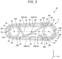
- FIG. 3 is a view as seen from a direction of an arrow A (Z-axis direction) in FIG. 2 .
- FIG. 4 is a view as seen from a direction of an arrow B (X-axis direction) in FIG. 2 .
- FIG. 1 an X-axis, a Y-axis, and a Z-axis as three axes orthogonal to one another are set and the same three axes are respectively shown in FIGS. 2 to 4 .
- Z-axis directions show vertical directions and an XY-plane shows a horizontal plane.
- FIGS. 1 , 2 , and 4 Upward and downward directions in FIGS. 1 , 2 , and 4 are the same as the vertical directions. Upsides (+Z-axis sides) in FIGS. 1 , 2 , and 4 are also referred to as “upper” and downsides (-Z-axis sides) are also referred to as “lower”. Regarding a robot arm 22, a first arm 23, a second arm 24, etc., right sides (+X-axis sides) in FIGS. 1 , 2 , and 3 are referred to as “proximal ends” or “proximal end portions” and left sides (-X-axis sides) are referred to as “distal ends” or “distal end portions”.
- vertical includes not only a case aligned with vertical but also cases slightly inclined within e.g., ⁇ 10° relative to vertical.
- parallel includes not only a case where two objects are in parallel but also cases where two objects are slightly inclined within e.g., ⁇ 10° from parallel.
- a robot system 1 shown in FIG. 1 includes a robot 2 and a robot control apparatus 9 controlling driving of the robot 2.
- the robot 2 in the embodiment is a scalar robot, i.e., a horizontal articulated robot and used for various kinds of work (hereinafter, simply referred to as "work") e.g., holding, transportation, assembly, processing, and inspection of workpieces including electronic components.
- work e.g., holding, transportation, assembly, processing, and inspection of workpieces including electronic components.
- the application of the robot 2 is not particularly limited.
- the robot of the present disclosure may be another than the scalar robot, e.g., a six-axis articulated robot, a dual-arm robot, or the like.
- the robot 2 includes a base 21, the robot arm 22 rotatably coupled to the base 21.
- the base 21 is fixed to a floor surface 10 parallel to a horizontal plane.
- the robot control apparatus 9 is placed inside of the base 21, the robot control apparatus 9 is placed. Note that, unlike the illustrated configuration, the robot control apparatus 9 may be placed outside of the base 21.
- the robot arm 22 includes the first arm 23 having a proximal end portion coupled to the base 21 and rotating around a first rotation axis J1 along vertical directions relative to the base 21 and the second arm 24 having a proximal end portion coupled to a distal end portion of the first arm 23 and rotating around a second rotation axis J2 along the vertical directions relative to the first arm 23.
- the first arm 23 rotates within a predetermined angle range around the first rotation axis J1 within a horizontal plane and the second arm 24 rotates within a predetermined angle range around the second rotation axis J2 within a horizontal plane above the first arm 23.
- a working head 25 is provided in a distal end portion of the second arm 24.
- the working head 25 has a spline nut 251 and a ball screw nut 252 coaxially placed with each other in the distal end portion of the second arm 24 and a spline shaft 253 inserted into the spline nut 251 and the ball screw nut 252.
- the spline nut 251 is located in the upper part of the ball screw nut 252 and fixed relative to the ball screw nut 252.
- the spline shaft 253 is rotatable around a third rotation axis J3 as a center axis thereof along the vertical directions and movable in upward and downward directions along the third rotation axis J3 relative to the second arm 24.
- An end effector 26 is attached to a lower end portion of the spline shaft 253.
- the end effector 26 is detachable and one suitable for intended work is appropriately selected.
- the end effector 26 includes e.g., a hand gripping a workpiece as an object to be assembled or processed, a tool for chucking, drilling, grinding, polishing, or the like, and a painting tool such as a spray gun.
- the robot 2 includes a first joint actuator 27 as a joint portion coupling the base 21 and the first arm 23 and rotating the first arm 23 around the first rotation axis J1 relative to the base 21, and a second joint actuator 28 as a joint portion coupling the first arm 23 and the second arm 24 and rotating the second arm 24 around the second rotation axis J2 relative to the first arm 23.
- the first arm 23 is coupled to the base 21 at a predetermined distance apart from an upper surface 210 of the base 21 by the first joint actuator 27.
- the second arm 24 is coupled to the first arm 23 at a predetermined distance apart from an upper surface 230 of the first arm 23 by the second joint actuator 28.
- the robot 2 includes a first drive mechanism 291 rotating the spline nut 251 to rotate the spline shaft 253 around the third rotation axis J3, and a second drive mechanism 292 rotating the ball screw nut 252 to move the spline shaft 253 upward and downward in directions along the third rotation axis J3.
- the spline shaft 253 rotates in a predetermined direction around the third rotation axis J3 by actuation of the first drive mechanism 291, and the end effector 26 rotates in the same direction with the rotation.
- the spline shaft 253 moves in an axial direction of the third rotation axis J3 by actuation of the second drive mechanism 292, and the end effector 26 moves in the same direction with the movement, that is, moves upward or downward.
- the first joint actuator 27, the second joint actuator 28, the first drive mechanism 291, and the second drive mechanism 292 respectively have motors, reducers, encoders, etc.
- the respective motors and the respective encoders are respectively electrically coupled to the robot control apparatus 9.
- the respective encoders detect rotation position information of the corresponding motors and transmit the information to the robot control apparatus 9.
- the robot control apparatus 9 controls energization conditions of the respective motors via motor drivers (not shown) based on the rotation position information of the respective motors received from the respective encoders.
- the first arm 23, the second arm 24, and the spline shaft 253 are respectively actuated, and the attitude of the robot arm 22 changes over time according to a predetermined program and desired work may be performed.
- motor 281 the motor of the second joint actuator 28
- reducer 282 the reducer of the second joint actuator 28
- encoder 283 the encoder of the second joint actuator 28
- the reducer 282, the motor 281, and the encoder 283 are sequentially arranged from the downside to the upside, i.e., in the +Z-axis direction and coupled.
- the motor 281 and the encoder 283 are placed in a first placement portion 31, which will be described later.
- the motor 281 has an output shaft 281A at the -Z-axis side.
- the reducer 282 is fixed to the output shaft 281A and fixed to the first arm 23.
- the second arm 24 has a base 3 including a frame-shaped member forming a basic skeleton of the second arm 24.
- the base 3 has a function of supporting and protecting mounted objects mounted on the second arm 24 including the above described second joint actuator 28, first drive mechanism 291, and second drive mechanism 292 (hereinafter, also simply referred to as "mounted objects").
- the base 3 is formed by the frame-shaped member having the first placement portion 31, a second placement portion 32, first beams 33, second beams 34, third beams 35, and fourth beams 36 appropriately combined into a desired three-dimensional shape.
- the base 3 is the frame-shaped member, and thereby, the weight of the second arm 24 may be made lighter than that of a plate-shaped base in related art. Even when the base 3 is the frame-shaped member, a sufficient strength may be secured for the following reasons. As below, the reasons will be specifically explained.
- the first placement portion 31 and the second placement portion 32 are placed apart along the X-axis directions.
- the first placement portion 31 is located in a proximal end portion of the base 3 and includes a ring-shaped, particularly, a circular ring-shaped member having an insertion hole 310 inside.
- the insertion hole 310 includes a through hole formed in the center part of the first placement portion 31 and penetrating in the Z-axis directions. As seen from a direction of an arrow A in FIG. 2 , the center of the insertion hole 310 is substantially equal to the center of the whole first placement portion 31 and coincides with the second rotation axis J2.
- the first placement portion 31 has an upper surface 311, a lower surface 312, and an inner circumferential surface 313 of the insertion hole 310, and a shoulder portion of a motor case of the motor 281 forming the second joint actuator 28 is in direct or indirect contact with the upper surface 311 and the inner circumferential surface 313.
- the motor 281 is fixed with the shoulder portion of the motor case fitted in the insertion hole 310.
- the output shaft 281A of the motor 281 is inserted into the insertion hole 310 without contact with the inner circumferential surface 313 and fixed to an input shaft (not shown) of the reducer 282.
- the first placement portion 31 is formed by the ring-shaped member, particularly, the circular ring-shaped member, and thereby, first, the strength of the first placement portion 31 may be increased.
- the first placement portion 31 holding the second joint actuator 28 having a considerably heavy weight may counter forces including inertia forces, centrifugal forces, and impact forces received from the respective directions on the horizontal plane with the actuation of the robot arm 22 by the sufficient strength.
- the motor 281 forming the second joint actuator 28 may be properly held by a force equal over the entire circumference and the second joint actuator 28 may be stably supported regardless of whether the robot arm 22 is actuated or stopped.
- the first placement portion 31 in the embodiment has an inner edge and an outer edge in circular shapes. Note that the portion is not limited to the configuration. For example, at least one of the inner edge and the outer edge may have an oval shape or a polygonal shape such as a rectangular shape.
- the first placement portion 31 is not limited to the above described configuration, but may be e.g., an arc-shaped member with a part of the ring shape cut out, or all or part thereof may be a plate-shaped member, a bar-shaped member, or a net-shaped member. Further, the first placement portion 31 may be formed by a solid body or a hollow body or the members may be appropriately combined.
- the inner diameter of the insertion hole 310 of the first placement portion 31 in the embodiment is constant along the Z-axis directions.
- the hole is not limited to the configuration, but the inner diameter of the insertion hole 310 may change in a stepwise manner or a continuous manner along the Z-axis directions. That is, the shape, dimensions, etc. of the inner circumferential surface 313 of the insertion hole 310 are appropriately determined according to the shape of the held motor case of the motor 281 or the like.
- the inner diameter of the insertion hole 310 changes in a stepwise manner or a continuous manner along the Z-axis directions, that contributes to a strength increase of the first placement portion 31 itself and thus contributes to a strength increase of the whole base 3.
- the second placement portion 32 is a portion located in a distal end portion of the base 3, into which the spline nut 251 and the ball screw nut 252 as supporting portions are placed and fixed.
- the second placement portion 32 includes a ring-shaped, particularly, a circular ring-shaped member having an insertion hole 320 inside.
- the insertion hole 320 includes a through hole formed in the center part of the second placement portion 32 and penetrating in the Z-axis directions. As seen from the direction of the arrow A, the center of the insertion hole 320 is substantially equal to the center of the whole second placement portion 32 and coincides with the third rotation axis J3.
- the second placement portion 32 has an upper surface 321, a lower surface 322, and an inner circumferential surface 323 of the insertion hole 320, and a lower portion of the ball screw nut 252 is in direct or indirect contact with the upper surface 321 and fixed. Note that the lower portion of the ball screw nut 252 may be in contact with the inner circumferential surface 323. Further, the spline shaft 253 is inserted into the insertion hole 320 without contact with the inner circumferential surface 323.
- the second placement portion 32 is formed by the ring-shaped member, particularly, the circular ring-shaped member, and thereby, first, the strength of the second placement portion 32 may be increased.
- the second placement portion 32 holding the working head 25 having a considerably heavy weight, the end effector 26 at the distal end side thereof, etc. may counter various external forces including inertia forces, centrifugal forces, and impact forces received from the respective directions on the horizontal plane and the Z-axis directions with the actuation of the robot arm 22 by the sufficient strength.
- the ball screw nut 252 forming the supporting portion may be properly held over a wide range, and the working head 25 etc. may be stably supported regardless of whether the robot arm 22 is actuated or stopped. Therefore, the spline shaft 253 may be stably rotated and moved upward and downward without wobbling or the like.
- Both the first placement portion 31 and the second placement portion 32 are formed by the circular ring-shaped members, and thereby, the strength of a lower portion of the base 3 may be further increased.
- the position relationship between the spline nut 251 and the ball screw nut 252 may be upside down. That is, the ball screw nut 252 may be fixed to the upper portion of the spline nut 251. In this case, the spline nut 251 is supported and fixed to the second placement portion 32 and, even in this case, the same effects as the above described first and second effects may be exerted.
- the second placement portion 32 in the embodiment has an inner edge and an outer edge in circular shapes. Note that the portion is not limited to the configuration. For example, at least one of the inner edge and the outer edge may have an oval shape or a polygonal shape such as a rectangular shape.
- the second placement portion 32 is not limited to the above described configuration, but may be e.g., an arc-shaped member with a part of the ring shape cut out, or all or part thereof may be a plate-shaped member, a bar-shaped or net-shaped member. Further, the second placement portion 32 may be formed by a solid member or a hollow member or the members may be appropriately combined.
- the inner diameter of the insertion hole 320 of the second placement portion 32 in the embodiment is constant along the Z-axis directions.
- the hole is not limited to the configuration, but the inner diameter of the insertion hole 320 may change in a stepwise manner or a continuous manner along the Z-axis directions. That is, the shape, dimensions, etc. of the inner circumferential surface 323 of the insertion hole 320 are appropriately determined according to the shape of the held ball screw nut 252 or the like.
- the inner diameter of the insertion hole 320 changes in a stepwise manner or a continuous manner along the Z-axis directions, that contributes to a strength increase of the second placement portion 32 itself and thus contributes to a strength increase of the whole base 3.
- the outer diameter of the second placement portion 32 is smaller than the outer diameter of the first placement portion 31 and, accordingly, the inner diameter of the insertion hole 320 is smaller than the inner diameter of the insertion hole 310.
- the shape of the part formed by the first placement portion 31, the second placement portion 32, and a pair of first beams 33A, 33B placed over these portions is a tapered shape from the proximal end toward the distal end, and the base 3 secures the sufficient strength and achieves an efficient weight distribution without excess as a whole.
- the hole is not limited to that, but the inner diameter of the insertion hole 320 may be equal to or larger than the inner diameter of the insertion hole 310.
- the pair of first beams 33A, 33B may be parallel.
- a line segment connecting the center parts of the first placement portion 31 and the second placement portion 32, i.e., a line segment SL connecting the center of the insertion hole 310 and the center of the insertion hole 320 is parallel to the X-axis.
- the first beams 33 are beams placed over between the first placement portion 31 and the second placement portion 32. That is, the first beams 33 couple the first placement portion 31 and the second placement portion 32 and fix the position relationship between the first placement portion 31 and the second placement portion 32.
- the first beams 33 serve to form the basic skeleton of the lower portion of the base 3 with the first placement portion 31 and the second placement portion 32.
- the first beams 33 form bar shapes extending substantially along the X-axis directions and, in the embodiment, the first beams 33 are provided symmetrically with respect to the line segment SL as seen from the direction of the arrow A. Thereby, the strength of the base 3 may be increased.
- first beam 33A the first beam 33 located at the +Y-axis side of the line segment SL
- first beam 33B the first beam 33 located at the -Y-axis side of the line segment SL
- first beam 33B the first beam 33 located at the -Y-axis side of the line segment SL
- the lower portion of the base 3 refers to a part formed by the first placement portion 31, the second placement portion 32, the first beam 33A, the first beam 33B, and the two fourth beams 36, which will be described later, located on the same horizontal plane.
- the first beam 33A and the first beam 33B have linear shapes.
- the first beam 33A and the first beam 33B are inclined relative to the line segment SL to increase the separation distance from each other toward the +X-axis side.
- the first beam 33A and the first beam 33B are placed symmetrically with respect to the line segment SL as seen in the direction of the arrow A. Note that, not limited to those, but the first beam 33A and the first beam 33B may be asymmetrical with respect to the line segment SL.
- the first beam 33A and the first placement portion 31, the first beam 33B and the first placement portion 31, the first beam 33A and the second placement portion 32, and the first beam 33B and the second placement portion 32 are respectively directly coupled.
- the coupling portions thereof may be joined and fixed by e.g., a method of welding, brazing such as soldering, bonding using adhesive agents, riveting, screwing, bolting, or the like or fixed via fixing members (not shown). Or, these may be indirectly coupled via other members, e.g., the third beams 35, the fourth beams 36, which will be described later, or any other coupling members.
- the first beams 33 are not limited to the illustrated linear shapes, but, for example, at least one of the first beam 33A and the first beam 33B may have one, two, or more portions curved or bent (hereinafter, represented by "curved") to project toward the +Z-axis side, the -Z-axis side, the +X-axis side, the -X-axis side, the +Y-axis side, or the -Y-axis side.
- the first beam 33A and the first beam 33B may have portions curved to be closer or coupled to each other near the centers thereof in the longitudinal direction.
- the first beams 33 may be in shapes having branch portions branched into a plurality of portions in the middle or near the end part thereof or shapes having crossing portions in which a plurality of wire materials cross. In these cases, the first beams 33 have one ends coupled to the second beams 34, the third beams 35, or the fourth beams 36 or coupled to the first placement portion 31 or the second placement portion 32 via the third beams 35 or the fourth beams 36.
- the first beam 33A and the first beam 33B may be curved to project in the same direction or projected to curve in opposite directions to each other.
- a coupling portion 30A between the first placement portion 31 and the first beam 33A is located at the -X-axis side and the +Y-axis side of the outer edge of the first placement portion 31.
- a coupling portion 30B between the first placement portion 31 and the first beam 33B is located at the -X-axis side and the -Y-axis side of the outer edge of the first placement portion 31.
- the first beam 33A and the first beam 33B are coupled to different positions of the first placement portion 31, and thereby, the strength of the base 3 may be increased.
- a coupling portion 30C between the second placement portion 32 and the first beam 33A is located at the +X-axis side and the +Y-axis side of the outer edge of the second placement portion 32.
- a coupling portion 30D between the second placement portion 32 and the first beam 33B is located at the +X-axis side and the -Y-axis side of the outer edge of the second placement portion 32.
- the first beam 33A and the first beam 33B are coupled to different positions of the second placement portion 32, and thereby, the strength of the base 3 may be increased.
- the second beams 34 are beams placed over between the first placement portion 31 and the second placement portion 32 in locations at the upside of the first beams 33.
- the second beams 34 have a function of increasing the strength of the base 3 and protecting the mounted objects on the second arm 24.
- the second beams 34 are formed by a single continuous wire material, one end portion and the other end portion of the wire material are respectively coupled to the same or different locations of the first placement portion 31, and the center part of the wire material in the longitudinal direction has a shape folded back in a position slightly over the second placement portion 32 at the -X-axis side as seen from the Z-axis direction.
- the second beams 34 form arch shapes curving and projecting toward the axial direction of the second rotation axis J2, i.e., the +Z-axis side relative to the first beam 33A and the first beam 33B.
- the second beams 34 have projecting portions 340 projecting toward the +Z-axis side relative to the first beam 33A and the first beam 33B.
- the part located at the +Y-side of the line segment SL as seen from the direction of the arrow A is referred to as "second beam 34A” and the part located at the -Y-side of the line segment SL is referred to as "second beam 34B".
- second beam 34A and the second beam 34B are symmetrically provided with respect to the line segment SL. According to the configuration, the strength of the base 3 may be increased.
- the second beam 34A and the second beam 34B have shapes symmetrical with respect to the line segment SL as seen in the direction of the arrow A. Note that, not limited to those, but the second beam 34A and the second beam 34B may be asymmetrical with respect to the line segment SL.
- a center of gravity G of the base 3 is eccentrically located closer to the first placement portion 31 side than the second placement portion 32. That is, the center of gravity G of the base 3 is located at the proximal end side (+X-axis side) of a midpoint SP of the line segment SL as seen from the direction of the arrow A. Thereby, the weight of the part at the distal end side (-X-axis side) may be made lighter than that of the part at the proximal end side (+X-axis side) of the second arm 24. As a result, an inertia force (inertia) of the rotation of the second arm 24 around the second rotation axis J2 may be reduced. That is, the rotation speed of the second arm 24 may be made higher and work may be performed more quickly or energy necessary for the rotational driving of the second arm 24 may be reduced.
- Top parts 341 of the projecting portions 340 of the second beam 34A and the second beam 34B are located at heights to surround to house the mounted objects inside of the projecting portions 340 and protect the mounted objects in good condition.
- the respective top parts 341 are in the same position in the X-axis directions.
- the respective top parts 341 of the second beam 34A and the second beam 34B are eccentrically located closer to the first placement portion 31 side than the second placement portion 32. That is, the respective top parts 341 are located at the proximal end side (+X-axis side) of the midpoint SP of the line segment SL as seen from the direction of the arrow A.
- a larger mounted object i.e., a mounted object having a larger height in the Z-axis directions, having a larger width in the Y-axis directions, or having both is placed in the position eccentrically located at the +X-axis side of the base 3.
- the mounted object is the second joint actuator 28.
- the respective top parts 341 are eccentrically located closer to the first placement portion 31 side than the second placement portion 32, and thereby, even the larger mounted object may be surrounded to be reliably housed between the projecting portions 340 and protected.
- the parts at the proximal end side (+X-axis side) of the top parts 341 of the projecting portions 340 have larger degrees of curves, i.e., average values of curvature of the curves than the parts at the distal end side (-X-axis side) of the top parts 341 of the projecting portions 340.
- the parts are not limited to the configurations.
- the parts at the proximal end side of the top parts 341 of the projecting portions 340 and the parts at the distal end side of the top parts 341 of the projecting portions 340 may have the same average values of curvature of the curves or at least ones may have linear shapes.
- the respective projecting portions 340 of the second beams 34A and 34B have shapes at a larger separation distance from each other as the portions are separated from the first beams 33A and 33B, that is, the positions in the Z-axis directions are closer toward the +Z-axis side.
- larger mounted objects e.g., the motor 281, the encoder 283, etc. may be housed and placed between the second beam 34A and the second beam 34B, particularly, in the upside space between the projecting portions 340 thereof, and the larger mounted objects may be sufficiently protected.
- directions in which the second arm 24 extends are along the X-axis and directions perpendicular to the X-axis within the plane in which the first arm 23 and the second arm 24 rotate are along the Y-axis.
- the top parts 341 are the largest in the distance between the pair of projecting portions 340 along the Y-axis.
- the weight of the part at the distal end side may be made lighter than that of the part at the proximal end side of the second arm 24.
- an inertia force (inertia) of the rotation of the second arm 24 around the second rotation axis J2 may be reduced. That is, the rotation speed of the second arm 24 may be made higher and work may be performed more quickly or energy necessary for the rotational driving of the second arm 24 may be reduced.
- the second beam 34A and the first placement portion 31 and the second beam 34B the and first placement portion 31 are respectively directly coupled.
- the coupling portions thereof may be joined and fixed by e.g., a method of welding, brazing such as soldering, bonding using adhesive agents, riveting, screwing, bolting, or the like or fixed via fixing members (not shown). Or, these may be indirectly coupled via other members, e.g., the third beams 35, the fourth beams 36, which will be described later, or any other coupling members.
- a coupling portion 30E between the first placement portion 31 and the second beam 34A is located at the +X-axis side and the +Y-axis side of the outer edge of the first placement portion 31.
- a coupling portion 30F between the first placement portion 31 and the second beam 34B is located at the +X-axis side and the -Y-axis side of the outer edge of the first placement portion 31.
- the proximal end of the second beam 34A and the proximal end of the second beam 34B are coupled to the different positions of the first placement portion 31, and thereby, the strength of the base 3 may be increased.
- the proximal end of the second beam 34A and the proximal end of the second beam 34B may be coupled to the same position of the first placement portion 31.
- the second beams 34 may be in shapes having branch portions branched into a plurality of portions in the middle or near the end part thereof or shapes having crossing portions in which a plurality of wire materials cross. In these cases, the second beams 34 may have one ends coupled to the first beams 33, the third beams 35, or the fourth beams 36 or coupled to the first placement portion 31 or the first beams 33 via the third beams 35 or the fourth beams 36.
- the third beams 35 reinforce the second beams 34. That is, by provision of the third beams 35, the curved shapes of the whole second beams 34, particularly, the shapes of the projecting portions 340 may be held more reliably against various external forces applied to the base 3. Thereby, the strength of the second beams 34 and thus the strength of the whole base 3 may be sufficiently increased.
- the third beams 35 extend substantially in the Z-axis directions or directions slightly inclined relative to the Z-axis and have substantially linear shapes. Further, in the illustrated configuration, 13 of the third beams 35 are provided.
- the third beams 35 include the beams coupling the first placement portion 31 and the second beams 34, the beams coupling the first beams 33 and the second beams 34, and the beams coupling the second placement portion 32 and the second beams 34.
- the third beams 35 couple the second beams 34 and counterpart members such as the first placement portion 31, the second placement portion 32, or the first beams 33, and have a function of reinforcing not only the second beams 34 but also the counterpart members. That is, by provision of the respective third beams 35, the strength of the whole base 3 may be sufficiently secured.
- the conditions of the dimensions including lengths and diameters, placements, coupling locations, the provided number, etc. of the third beams 35 are not limited to those of the illustrated configuration.
- the lower ends of the third beams 35 coupling the second placement portion 32 and the second beams 34 are located in parts different from the coupling portion 30C and the coupling portion 30D. Thereby, the upside spaces of the coupling portion 30C and the coupling portion 30D may be secured and the strength of the base 3 may be sufficiently obtained. Note that the lower ends of the third beams 35 may be coupled to the coupling portion 30C and the coupling portion 30D.
- the three third beams 35 coupling the parts near the coupling portion 30A between the first placement portion 31 and the first beam 33A and the projecting portion 340 of the second beam 34A are provided. These three third beams 35 are at different angles relative to the Z-axis in the longitudinal direction, and the upper end of the middle third beam 35 of the three is coupled to near the top part 341 of the second beam 34A.
- the three third beams 35 coupling the parts near the coupling portion 30B between the first placement portion 31 and the first beam 33B and the projecting portion 340 of the second beam 34B are provided. These three third beams 35 are at different angles relative to the Z-axis in the longitudinal direction, and the upper end of the middle third beam 35 of the three is coupled to near the top part 341 of the second beam 34B.
- the strengths of the projecting portions 340 requiring higher strengths, particularly, near the top parts 341 may be increased, and deformation of the second beams 34 when subjected to external forces and thus deformation of the whole base 3 may be prevented or suppressed more effectively.
- the mounted objects, particularly, the mounted objects in the first placement portion 31 may be sufficiently protected.
- the third beams 35 are not limited to the illustrated linear shapes, but may have e.g., one, two, or more portions curved to project in the X-axis directions or the Y-axis directions.
- the third beams 35 may be in shapes having branch portions branched into a plurality of portions in the middle or near the end part thereof or shapes having crossing portions in which a plurality of wire materials cross. In these cases, the third beams 35 may have one ends coupled to other third beams 35 or the fourth beams 36 or coupled to the first placement portion 31, the second placement portion 32, or the first beams 33 via the other third beams 35 or the fourth beams 36.
- the coupling members include e.g., grid-like members, net-like members, honeycomb structures, porous structures, and plate-like members having a plurality of small holes or slits penetrating in plate thickness directions.
- the fourth beams 36 couple the first beam 33A and the first beam 33B.
- the strength of the lower portion of the base 3 may be increased and thus the strength of the whole base 3 may be increased.
- Two of the fourth beams 36 are provided in the illustrated configuration. Note that the conditions of the dimensions including lengths and diameters, placements, coupling locations, the provided number, etc. of the fourth beams 36 are not limited to those of the illustrated configuration.
- the fourth beams 36 have a function of mounting and fixing the mounted objects of the second arm 24, e.g., the first joint actuator 27 and the second joint actuator 28 onto the upper portions thereof.
- the fourth beams 36 have screw holes or bolt holes (not shown) for fixing the first joint actuator 27, the second joint actuator 28, etc.
- the strength of the whole base 3, particularly, the lower portion of the base 3 may be increased and the mounted objects may be supported more reliably.
- the strength against the force may be increased.
- the fourth beams 36 may be in shapes having branch portions branched into a plurality of portions in the middle or near the end part thereof or shapes having crossing portions in which a plurality of wire materials cross. Further, the fourth beams 36 may have one ends coupled to the first placement portion 31, the second placement portion 32, or the third beams 35.
- the respective members of the first placement portion 31, the second placement portion 32, the first beams 33, the second beams 34, the third beams 35, and the fourth beams 36 may be respectively formed by solid bodies or hollow bodies.
- the strengths of the members and the base 3 may be further increased.
- the strengths of the members and the whole base 3 may be sufficiently secured and the weight of the base 3 may be further reduced.
- the effects may be exerted more remarkably, and, when all or part of the second beams 34 are formed by hollow bodies, the effects may be exerted more remarkably.
- the first beams 33 and the second beams 34 are formed by hollow bodies. Thereby, the strengths of the first beams 33 and the second beams 34 and the strength of the whole base 3 may be sufficiently secured and the weight of the base 3 may be further reduced.
- the robot 2 of the present disclosure may have at least one fifth beam coupling the first placement portion 31 or the second placement portion 32 and the first beam 33, at least one sixth beam coupling the second beam 34A and the second beam 34B, at least one seventh beam coupling the first beam 33A and the second beam 34B or the first beam 33B and the second beam 34A, at least one eighth beam coupling the third beams 35, the fourth beams 36, or the third beam 35 and the fourth beam 36, etc.
- the constituent materials of the frame-shaped member forming the base 3 or the first placement portion 31, the second placement portion 32, the first beams 33, the second beams 34, the third beams 35, the fourth beams 36, etc. as the respective configurations of the frame-shaped member are not particularly limited.
- Materials preferable for balance between the strength increase and the weight reduction of the base 3 may include e.g., various metal materials including iron and iron alloys such as stainless steel, aluminum or aluminum alloys, copper or copper alloys, titanium or titanium alloys, various ceramics materials, various resin materials (particularly, hard resin materials) including polyester such as polyethylene, polypropylene, polystyrene, and polyethylene terephthalate, acrylic resins such as polycarbonate and polymethylmethacrylate, polyamide, and fluorine resin, high-strength fibrous materials such as aramid, Kevlar (registered trademark), ZYLON (registered trademark), metal fiber, and carbon fiber or materials containing the high-strength fibrous materials (e.g., fiber-reinforced plastic), various ceramics materials, and various carbon materials. Or, composite materials formed by arbitrary combination of two or more of the materials may be used. All of the above described respective configurations may be formed using the same material or part of the configurations may be formed using other materials than those of
- the frame-shaped member forming the base 3 or the respective configurations of the frame-shaped member may be in conditions in which residual stress generated at e.g., molding, processing, coupling by welding or the like, assembly, etc. remains or in conditions in which residual stress is removed or relaxed by e.g., thermal treatment.
- the former case is preferable because residual stress of compression is mainly left and the strength of the whole base 3 may be further increased.
- the latter case is preferable because residual stress of tension is mainly removed and the joint strength of the joint portions and the strength of the whole base 3 may be further increased.
- thermal treatment may be performed on the whole base 3, the whole second beams 34, or the projecting portions 340 to remove or relax residual stress of tension or bending left in the second beams 34, and thereby, the joint strengths of the coupling portions 30E, 30F, the joint strengths to the third beams 35, the strengths of the second beams 34 themselves, and thus, the strength of the whole base 3 may be further increased.
- All or part of the respective configurations of the frame-shaped member forming the base 3, i.e., the first placement portion 31, the second placement portion 32, the first beams 33, the second beams 34, the third beams 35, the fourth beams 36, etc. may be integrally formed, not joined. Thereby, compared to a case where the configurations are joined, the strengths of the joint portions may be made higher.
- the frame-shaped member forming the base 3 or the configurations thereof may be manufactured through various methods including e.g., various kinds of cold or hot plastic forming such as milling, rolling, forging, press molding, compression molding, extrusion molding, tensile molding, wire drawing, drawing, spinning, and bending, casting, injection molding, hot isostatic pressing (HIP), cold isostatic pressing (CIP), cutting, grinding, shaving, electrical discharge machining, laser machining, casting, modeling using 3D printers, powder sintering, and metal injection molding (MIM) or methods formed by appropriate combination of the methods.
- various dies for pressing, injection molding, etc. may be fabricated by modeling using 3D printers and the frame-shaped member or the respective configurations thereof may be manufactured using the dies.
- the robot 2 includes the base 21, the first arm 23 coupled rotatably around the first rotation axis J1 relative to the base 21, the second arm 24 having the base 3 formed by the frame-shaped member and rotating around the second rotation axis J2 parallel to the first rotation axis J1 relative to the first arm 23, the spline shaft 253 as the shaft placed at the opposite side to the first arm 23 of the second arm 24, the second joint actuator 28 as the drive unit rotationally driving the second arm 24 around the second rotation axis J2 relative to the first arm 23, and the spline nut 251 and the ball screw nut 252 as supporting portions supporting the spline shaft 253 to rotate around the third rotation axis J3 parallel to the second rotation axis J2 and move along the axial direction of the third rotation axis J3.
- the base 3 includes the first placement portion 31 in which the second joint actuator 28 is placed, the second placement portion 32 in which the spline nut 251 and the ball screw nut 252 are placed, the first beams 33 placed over between the first placement portion 31 and the second placement portion 32, and the second beams 34 placed over between the first placement portion 31 and the second placement portion 32 and having the projecting portions 340 projecting toward the axial direction of the second rotation axis J2.
- the sufficient strength of the base 3 particularly, the strength in the direction twisting around the extension direction of the second arm 24 may be secured and the weight of the second arm 24 may be reduced. That is, the strength increase and the weight reduction of the base 3 may be balanced.
- the robot 2 performs work, that contributes to an increase in work speed and power consumption saving.
- the second beams 34 may have shapes projecting toward the -Z-axis side.
- first beams 33 are provided symmetrically with respect to the line segment SL connecting the center parts of the first placement portion 31 and the second placement portion 32. Thereby, the strength of the base 3 may be further increased.
- the second beams 34 are provided symmetrically with respect to the line segment SL connecting the center parts of the first placement portion 31 and the second placement portion 32. Thereby, the strength of the base 3 may be further increased.
- the separation distance between the respective projecting portions 340 of the pair of second beams 34 is larger as the portions are farther away from the first beams 33. That is, as described above, the directions in which the second arm 24 extends are along the X-axis and the directions perpendicular to the X-axis within the plane in which the first arm 23 and the second arm 24 rotate are along the Y-axis. Here, in the distance along the Y-axis between the pair of projecting portions 340, the top parts 341 are the largest. Thereby, the larger mounted objects and the heavier mounted objects may be housed and placed inside of the projecting portions 340 of the pair of second beams 34.
- the separation distance between the pair of second beams 34 may be smaller as the beams are farther away from the first beams 33, and the separation distance between the pair of second beams 34 may be the same regardless of the distances from the first beams 33.
- the base 3 includes the third beams 35 reinforcing the second beams 34. Thereby, the strength of the base 3 may be further increased.
- the third beams 35 may be omitted.
- the center of gravity G of the base 3 is eccentrically located closer to the first placement portion 31 side than the second placement portion 32. Thereby, the weight of the distal end side portion of the second arm 24 is made lighter than that of the proximal end side portion, and the inertia force of the rotation of the second arm 24 around the second rotation axis J2 may be reduced. That is, the rotation speed of the second arm 24 may be increased and the work may be performed more quickly, or the energy necessary for rotational driving of the second arm 24 may be reduced.
- the center of gravity G of the base 3 may be eccentrically located closer to the second placement portion 32 side than the first placement portion 31, or located near the midway between the first placement portion 31 and the second placement portion 32, i.e., near the midpoint SP of the line segment SL.
- the top parts 341 of the projecting portions 340 are eccentrically located closer to the first placement portion 31 side than the second placement portion 32. Thereby, even the larger mounted object, particularly, the second joint actuator 28 as the mounted object at the larger height in the Z-axis directions is placed at the proximal end side of the base 3, the second joint actuator 28 may be sufficiently housed and protected inside of the projecting portions 340 of the second beams 34. Accordingly, the weight of the distal end side portion of the second arm 24 is made lighter relative to the proximal end side portion, and the inertia force of the rotation of the second arm 24 around the second rotation axis J2 may be reduced. That is, the rotation speed of the second arm 24 may be increased and the work may be performed more quickly, or the energy necessary for rotational driving of the second arm 24 may be reduced.
- the second arm 24 may have a cover (not shown) detachably attached to the base 3.
- a cover detachably attached to the base 3.
- the cover e.g., a transparent or opaque plastic cover, i.e., a cover having a lighter weight and a sufficient strength may be used.
- the cover is not attached to the base 3.
- the above described configuration of the base 3 may be applied not only to the second arm 24 but also to the base of the first arm 23. Thereby, the weight of the whole robot arm 22 may be further reduced and that contributes to an increase in work speed and power consumption saving.
- the robot of the present disclosure is explained based on the illustrated embodiment, however, the present disclosure is not limited to that.
- the configurations of the respective parts may be replaced by any configurations having the same functions. Further, any other configuration may be added to the robot of the present disclosure.
Landscapes
- Engineering & Computer Science (AREA)
- Robotics (AREA)
- Mechanical Engineering (AREA)
- Manipulator (AREA)
Abstract
Description
- The present application is based on, and claims priority from
JP Application Serial Number 2022-204296, filed December 21, 2022 - The present disclosure relates to a robot.
- For example, a robot including a base, a first arm coupled to the base rotatably around a first rotation axis, a second arm coupled to the first arm rotatably around a second rotation axis parallel to the first rotation axis, and a working head supported by the second arm is known. The first arm and the second arm form a robot arm. In the robot, in view of reduction of an inertia force of the robot arm for responding faster movement, suppression of power consumption, etc., weight reduction of the respective parts of the robot arm, particularly, weight reduction of the second arm is required.
-
JP-A-2020-142309 - However, in the robot disclosed in
JP-A-2020-142309 - A robot according to an aspect of the present disclosure includes a base, a first arm coupled rotatably around a first rotation axis relative to the base, a second arm having a base formed by a frame-shaped member and rotating around a second rotation axis parallel to the first rotation axis relative to the first arm, a shaft placed at an opposite side to the first arm of the second arm, a drive unit rotationally driving the second arm around the second rotation axis relative to the first arm, and a supporting portion supporting the shaft to rotate around a third rotation axis parallel to the second rotation axis and move the shaft along an axial direction of the third rotation axis, wherein the base has a first placement portion in which the drive unit is placed, a second placement portion in which the supporting portion is placed, a first beam placed over between the first placement portion and the second placement portion, and a second beam placed over between the first placement portion and the second placement portion and having a projecting portion projecting toward an axial direction of the second rotation axis relative to the first beam.
-
-
FIG. 1 is an overall view of a robot system according to a first embodiment of a robot of the present disclosure. -
FIG. 2 is a perspective view of a base of a second arm of the robot shown inFIG. 1 . -
FIG. 3 is a view as seen from a direction of an arrow A inFIG. 2 . -
FIG. 4 is a view as seen from a direction of an arrow B inFIG. 2 . - As below, a robot of the present disclosure will be explained in detail based on embodiments shown in the accompanying drawings.
-
FIG. 1 is an overall view of a robot system according to a first embodiment of a robot of the present disclosure.FIG. 2 is a perspective view of a base of a second arm of the robot shown inFIG. 1 .FIG. 3 is a view as seen from a direction of an arrow A (Z-axis direction) inFIG. 2 .FIG. 4 is a view as seen from a direction of an arrow B (X-axis direction) inFIG. 2 . - In
FIG. 1 , an X-axis, a Y-axis, and a Z-axis as three axes orthogonal to one another are set and the same three axes are respectively shown inFIGS. 2 to 4 . Of the three axes, Z-axis directions show vertical directions and an XY-plane shows a horizontal plane. - Upward and downward directions in
FIGS. 1 ,2 , and4 are the same as the vertical directions. Upsides (+Z-axis sides) inFIGS. 1 ,2 , and4 are also referred to as "upper" and downsides (-Z-axis sides) are also referred to as "lower". Regarding arobot arm 22, afirst arm 23, asecond arm 24, etc., right sides (+X-axis sides) inFIGS. 1 ,2 , and3 are referred to as "proximal ends" or "proximal end portions" and left sides (-X-axis sides) are referred to as "distal ends" or "distal end portions". - In the specification, "vertical" includes not only a case aligned with vertical but also cases slightly inclined within e.g., ±10° relative to vertical. Further, in the specification, "parallel" includes not only a case where two objects are in parallel but also cases where two objects are slightly inclined within e.g., ±10° from parallel.
- A
robot system 1 shown inFIG. 1 includes arobot 2 and arobot control apparatus 9 controlling driving of therobot 2. - The
robot 2 in the embodiment is a scalar robot, i.e., a horizontal articulated robot and used for various kinds of work (hereinafter, simply referred to as "work") e.g., holding, transportation, assembly, processing, and inspection of workpieces including electronic components. Note that the application of therobot 2 is not particularly limited. Further, the robot of the present disclosure may be another than the scalar robot, e.g., a six-axis articulated robot, a dual-arm robot, or the like. - As shown in
FIG. 1 , therobot 2 includes abase 21, therobot arm 22 rotatably coupled to thebase 21. Thebase 21 is fixed to afloor surface 10 parallel to a horizontal plane. Inside of thebase 21, therobot control apparatus 9 is placed. Note that, unlike the illustrated configuration, therobot control apparatus 9 may be placed outside of thebase 21. - The
robot arm 22 includes thefirst arm 23 having a proximal end portion coupled to thebase 21 and rotating around a first rotation axis J1 along vertical directions relative to thebase 21 and thesecond arm 24 having a proximal end portion coupled to a distal end portion of thefirst arm 23 and rotating around a second rotation axis J2 along the vertical directions relative to thefirst arm 23. Thefirst arm 23 rotates within a predetermined angle range around the first rotation axis J1 within a horizontal plane and thesecond arm 24 rotates within a predetermined angle range around the second rotation axis J2 within a horizontal plane above thefirst arm 23. - A working
head 25 is provided in a distal end portion of thesecond arm 24. The workinghead 25 has aspline nut 251 and aball screw nut 252 coaxially placed with each other in the distal end portion of thesecond arm 24 and aspline shaft 253 inserted into thespline nut 251 and theball screw nut 252. Thespline nut 251 is located in the upper part of theball screw nut 252 and fixed relative to theball screw nut 252. Thespline shaft 253 is rotatable around a third rotation axis J3 as a center axis thereof along the vertical directions and movable in upward and downward directions along the third rotation axis J3 relative to thesecond arm 24. - An
end effector 26 is attached to a lower end portion of thespline shaft 253. Theend effector 26 is detachable and one suitable for intended work is appropriately selected. Theend effector 26 includes e.g., a hand gripping a workpiece as an object to be assembled or processed, a tool for chucking, drilling, grinding, polishing, or the like, and a painting tool such as a spray gun. - The
robot 2 includes a firstjoint actuator 27 as a joint portion coupling thebase 21 and thefirst arm 23 and rotating thefirst arm 23 around the first rotation axis J1 relative to thebase 21, and asecond joint actuator 28 as a joint portion coupling thefirst arm 23 and thesecond arm 24 and rotating thesecond arm 24 around the second rotation axis J2 relative to thefirst arm 23. - The
first arm 23 is coupled to thebase 21 at a predetermined distance apart from anupper surface 210 of thebase 21 by the firstjoint actuator 27. Thesecond arm 24 is coupled to thefirst arm 23 at a predetermined distance apart from anupper surface 230 of thefirst arm 23 by the secondjoint actuator 28. - Further, the
robot 2 includes afirst drive mechanism 291 rotating thespline nut 251 to rotate thespline shaft 253 around the third rotation axis J3, and asecond drive mechanism 292 rotating theball screw nut 252 to move thespline shaft 253 upward and downward in directions along the third rotation axis J3. Thespline shaft 253 rotates in a predetermined direction around the third rotation axis J3 by actuation of thefirst drive mechanism 291, and theend effector 26 rotates in the same direction with the rotation. Thespline shaft 253 moves in an axial direction of the third rotation axis J3 by actuation of thesecond drive mechanism 292, and theend effector 26 moves in the same direction with the movement, that is, moves upward or downward. - The first
joint actuator 27, the secondjoint actuator 28, thefirst drive mechanism 291, and thesecond drive mechanism 292 respectively have motors, reducers, encoders, etc. The respective motors and the respective encoders are respectively electrically coupled to therobot control apparatus 9. The respective encoders detect rotation position information of the corresponding motors and transmit the information to therobot control apparatus 9. Therobot control apparatus 9 controls energization conditions of the respective motors via motor drivers (not shown) based on the rotation position information of the respective motors received from the respective encoders. Thereby, thefirst arm 23, thesecond arm 24, and thespline shaft 253 are respectively actuated, and the attitude of therobot arm 22 changes over time according to a predetermined program and desired work may be performed. - Hereinafter, the motor of the second
joint actuator 28 is referred to as "motor 281", the reducer of the secondjoint actuator 28 is referred to as "reducer 282", and the encoder of the secondjoint actuator 28 is referred to as "encoder 283". - As shown in
FIG. 1 , thereducer 282, themotor 281, and theencoder 283 are sequentially arranged from the downside to the upside, i.e., in the +Z-axis direction and coupled. Themotor 281 and theencoder 283 are placed in afirst placement portion 31, which will be described later. Themotor 281 has anoutput shaft 281A at the -Z-axis side. Thereducer 282 is fixed to theoutput shaft 281A and fixed to thefirst arm 23. - Next, a structure of the
second arm 24 will be explained. - As shown in
FIGS. 1 to 4 , thesecond arm 24 has abase 3 including a frame-shaped member forming a basic skeleton of thesecond arm 24. Thebase 3 has a function of supporting and protecting mounted objects mounted on thesecond arm 24 including the above described secondjoint actuator 28,first drive mechanism 291, and second drive mechanism 292 (hereinafter, also simply referred to as "mounted objects"). - As shown in
FIG. 2 , thebase 3 is formed by the frame-shaped member having thefirst placement portion 31, asecond placement portion 32, first beams 33,second beams 34,third beams 35, andfourth beams 36 appropriately combined into a desired three-dimensional shape. Thebase 3 is the frame-shaped member, and thereby, the weight of thesecond arm 24 may be made lighter than that of a plate-shaped base in related art. Even when thebase 3 is the frame-shaped member, a sufficient strength may be secured for the following reasons. As below, the reasons will be specifically explained. - The
first placement portion 31 and thesecond placement portion 32 are placed apart along the X-axis directions. Thefirst placement portion 31 is located in a proximal end portion of thebase 3 and includes a ring-shaped, particularly, a circular ring-shaped member having aninsertion hole 310 inside. Theinsertion hole 310 includes a through hole formed in the center part of thefirst placement portion 31 and penetrating in the Z-axis directions. As seen from a direction of an arrow A inFIG. 2 , the center of theinsertion hole 310 is substantially equal to the center of the wholefirst placement portion 31 and coincides with the second rotation axis J2. - The
first placement portion 31 has anupper surface 311, alower surface 312, and an innercircumferential surface 313 of theinsertion hole 310, and a shoulder portion of a motor case of themotor 281 forming the secondjoint actuator 28 is in direct or indirect contact with theupper surface 311 and the innercircumferential surface 313. For example, themotor 281 is fixed with the shoulder portion of the motor case fitted in theinsertion hole 310. Further, theoutput shaft 281A of themotor 281 is inserted into theinsertion hole 310 without contact with the innercircumferential surface 313 and fixed to an input shaft (not shown) of thereducer 282. - The
first placement portion 31 is formed by the ring-shaped member, particularly, the circular ring-shaped member, and thereby, first, the strength of thefirst placement portion 31 may be increased. Especially, thefirst placement portion 31 holding the secondjoint actuator 28 having a considerably heavy weight may counter forces including inertia forces, centrifugal forces, and impact forces received from the respective directions on the horizontal plane with the actuation of therobot arm 22 by the sufficient strength. Second, themotor 281 forming the secondjoint actuator 28 may be properly held by a force equal over the entire circumference and the secondjoint actuator 28 may be stably supported regardless of whether therobot arm 22 is actuated or stopped. - The
first placement portion 31 in the embodiment has an inner edge and an outer edge in circular shapes. Note that the portion is not limited to the configuration. For example, at least one of the inner edge and the outer edge may have an oval shape or a polygonal shape such as a rectangular shape. - The
first placement portion 31 is not limited to the above described configuration, but may be e.g., an arc-shaped member with a part of the ring shape cut out, or all or part thereof may be a plate-shaped member, a bar-shaped member, or a net-shaped member. Further, thefirst placement portion 31 may be formed by a solid body or a hollow body or the members may be appropriately combined. - The inner diameter of the
insertion hole 310 of thefirst placement portion 31 in the embodiment is constant along the Z-axis directions. Note that the hole is not limited to the configuration, but the inner diameter of theinsertion hole 310 may change in a stepwise manner or a continuous manner along the Z-axis directions. That is, the shape, dimensions, etc. of the innercircumferential surface 313 of theinsertion hole 310 are appropriately determined according to the shape of the held motor case of themotor 281 or the like. When the inner diameter of theinsertion hole 310 changes in a stepwise manner or a continuous manner along the Z-axis directions, that contributes to a strength increase of thefirst placement portion 31 itself and thus contributes to a strength increase of thewhole base 3. - The
second placement portion 32 is a portion located in a distal end portion of thebase 3, into which thespline nut 251 and theball screw nut 252 as supporting portions are placed and fixed. Thesecond placement portion 32 includes a ring-shaped, particularly, a circular ring-shaped member having aninsertion hole 320 inside. Theinsertion hole 320 includes a through hole formed in the center part of thesecond placement portion 32 and penetrating in the Z-axis directions. As seen from the direction of the arrow A, the center of theinsertion hole 320 is substantially equal to the center of the wholesecond placement portion 32 and coincides with the third rotation axis J3. - The
second placement portion 32 has anupper surface 321, alower surface 322, and an innercircumferential surface 323 of theinsertion hole 320, and a lower portion of theball screw nut 252 is in direct or indirect contact with theupper surface 321 and fixed. Note that the lower portion of theball screw nut 252 may be in contact with the innercircumferential surface 323. Further, thespline shaft 253 is inserted into theinsertion hole 320 without contact with the innercircumferential surface 323. - The
second placement portion 32 is formed by the ring-shaped member, particularly, the circular ring-shaped member, and thereby, first, the strength of thesecond placement portion 32 may be increased. Especially, thesecond placement portion 32 holding the workinghead 25 having a considerably heavy weight, theend effector 26 at the distal end side thereof, etc. may counter various external forces including inertia forces, centrifugal forces, and impact forces received from the respective directions on the horizontal plane and the Z-axis directions with the actuation of therobot arm 22 by the sufficient strength. Second, theball screw nut 252 forming the supporting portion may be properly held over a wide range, and the workinghead 25 etc. may be stably supported regardless of whether therobot arm 22 is actuated or stopped. Therefore, thespline shaft 253 may be stably rotated and moved upward and downward without wobbling or the like. - Both the
first placement portion 31 and thesecond placement portion 32 are formed by the circular ring-shaped members, and thereby, the strength of a lower portion of thebase 3 may be further increased. - Note that, unlike the illustrated configuration, the position relationship between the
spline nut 251 and theball screw nut 252 may be upside down. That is, theball screw nut 252 may be fixed to the upper portion of thespline nut 251. In this case, thespline nut 251 is supported and fixed to thesecond placement portion 32 and, even in this case, the same effects as the above described first and second effects may be exerted. - The
second placement portion 32 in the embodiment has an inner edge and an outer edge in circular shapes. Note that the portion is not limited to the configuration. For example, at least one of the inner edge and the outer edge may have an oval shape or a polygonal shape such as a rectangular shape. - The
second placement portion 32 is not limited to the above described configuration, but may be e.g., an arc-shaped member with a part of the ring shape cut out, or all or part thereof may be a plate-shaped member, a bar-shaped or net-shaped member. Further, thesecond placement portion 32 may be formed by a solid member or a hollow member or the members may be appropriately combined. - The inner diameter of the
insertion hole 320 of thesecond placement portion 32 in the embodiment is constant along the Z-axis directions. Note that the hole is not limited to the configuration, but the inner diameter of theinsertion hole 320 may change in a stepwise manner or a continuous manner along the Z-axis directions. That is, the shape, dimensions, etc. of the innercircumferential surface 323 of theinsertion hole 320 are appropriately determined according to the shape of the heldball screw nut 252 or the like. When the inner diameter of theinsertion hole 320 changes in a stepwise manner or a continuous manner along the Z-axis directions, that contributes to a strength increase of thesecond placement portion 32 itself and thus contributes to a strength increase of thewhole base 3. - In the embodiment, the outer diameter of the
second placement portion 32 is smaller than the outer diameter of thefirst placement portion 31 and, accordingly, the inner diameter of theinsertion hole 320 is smaller than the inner diameter of theinsertion hole 310. Thereby, the shape of the part formed by thefirst placement portion 31, thesecond placement portion 32, and a pair offirst beams base 3 secures the sufficient strength and achieves an efficient weight distribution without excess as a whole. Note that the hole is not limited to that, but the inner diameter of theinsertion hole 320 may be equal to or larger than the inner diameter of theinsertion hole 310. Particularly, the pair offirst beams - A line segment connecting the center parts of the
first placement portion 31 and thesecond placement portion 32, i.e., a line segment SL connecting the center of theinsertion hole 310 and the center of theinsertion hole 320 is parallel to the X-axis. - The first beams 33 are beams placed over between the
first placement portion 31 and thesecond placement portion 32. That is, thefirst beams 33 couple thefirst placement portion 31 and thesecond placement portion 32 and fix the position relationship between thefirst placement portion 31 and thesecond placement portion 32. The first beams 33 serve to form the basic skeleton of the lower portion of thebase 3 with thefirst placement portion 31 and thesecond placement portion 32. The first beams 33 form bar shapes extending substantially along the X-axis directions and, in the embodiment, thefirst beams 33 are provided symmetrically with respect to the line segment SL as seen from the direction of the arrow A. Thereby, the strength of thebase 3 may be increased. - In this specification, the
first beam 33 located at the +Y-axis side of the line segment SL is referred to as "first beam 33A" and thefirst beam 33 located at the -Y-axis side of the line segment SL is referred to as "first beam 33B". Further, "the lower portion of thebase 3" refers to a part formed by thefirst placement portion 31, thesecond placement portion 32, thefirst beam 33A, thefirst beam 33B, and the twofourth beams 36, which will be described later, located on the same horizontal plane. - The
first beam 33A and thefirst beam 33B have linear shapes. Thefirst beam 33A and thefirst beam 33B are inclined relative to the line segment SL to increase the separation distance from each other toward the +X-axis side. - In the embodiment, the
first beam 33A and thefirst beam 33B are placed symmetrically with respect to the line segment SL as seen in the direction of the arrow A. Note that, not limited to those, but thefirst beam 33A and thefirst beam 33B may be asymmetrical with respect to the line segment SL. - The
first beam 33A and thefirst placement portion 31, thefirst beam 33B and thefirst placement portion 31, thefirst beam 33A and thesecond placement portion 32, and thefirst beam 33B and thesecond placement portion 32 are respectively directly coupled. The coupling portions thereof may be joined and fixed by e.g., a method of welding, brazing such as soldering, bonding using adhesive agents, riveting, screwing, bolting, or the like or fixed via fixing members (not shown). Or, these may be indirectly coupled via other members, e.g., thethird beams 35, thefourth beams 36, which will be described later, or any other coupling members. - Note that the
first beams 33 are not limited to the illustrated linear shapes, but, for example, at least one of thefirst beam 33A and thefirst beam 33B may have one, two, or more portions curved or bent (hereinafter, represented by "curved") to project toward the +Z-axis side, the -Z-axis side, the +X-axis side, the -X-axis side, the +Y-axis side, or the -Y-axis side. For example, thefirst beam 33A and thefirst beam 33B may have portions curved to be closer or coupled to each other near the centers thereof in the longitudinal direction. - The first beams 33 may be in shapes having branch portions branched into a plurality of portions in the middle or near the end part thereof or shapes having crossing portions in which a plurality of wire materials cross. In these cases, the
first beams 33 have one ends coupled to thesecond beams 34, thethird beams 35, or thefourth beams 36 or coupled to thefirst placement portion 31 or thesecond placement portion 32 via thethird beams 35 or the fourth beams 36. - Or, the
first beam 33A and thefirst beam 33B may be curved to project in the same direction or projected to curve in opposite directions to each other. - As shown in
FIG. 3 , acoupling portion 30A between thefirst placement portion 31 and thefirst beam 33A is located at the -X-axis side and the +Y-axis side of the outer edge of thefirst placement portion 31. Acoupling portion 30B between thefirst placement portion 31 and thefirst beam 33B is located at the -X-axis side and the -Y-axis side of the outer edge of thefirst placement portion 31. - As described above, the
first beam 33A and thefirst beam 33B are coupled to different positions of thefirst placement portion 31, and thereby, the strength of thebase 3 may be increased. - A
coupling portion 30C between thesecond placement portion 32 and thefirst beam 33A is located at the +X-axis side and the +Y-axis side of the outer edge of thesecond placement portion 32. Acoupling portion 30D between thesecond placement portion 32 and thefirst beam 33B is located at the +X-axis side and the -Y-axis side of the outer edge of thesecond placement portion 32. - As described above, the
first beam 33A and thefirst beam 33B are coupled to different positions of thesecond placement portion 32, and thereby, the strength of thebase 3 may be increased. - The second beams 34 are beams placed over between the
first placement portion 31 and thesecond placement portion 32 in locations at the upside of the first beams 33. The second beams 34 have a function of increasing the strength of thebase 3 and protecting the mounted objects on thesecond arm 24. - As shown in
FIGS. 2 and3 , in the embodiment, thesecond beams 34 are formed by a single continuous wire material, one end portion and the other end portion of the wire material are respectively coupled to the same or different locations of thefirst placement portion 31, and the center part of the wire material in the longitudinal direction has a shape folded back in a position slightly over thesecond placement portion 32 at the -X-axis side as seen from the Z-axis direction. - The second beams 34 form arch shapes curving and projecting toward the axial direction of the second rotation axis J2, i.e., the +Z-axis side relative to the
first beam 33A and thefirst beam 33B. In other words, thesecond beams 34 have projectingportions 340 projecting toward the +Z-axis side relative to thefirst beam 33A and thefirst beam 33B. - In this specification, of the
second beams 34, the part located at the +Y-side of the line segment SL as seen from the direction of the arrow A is referred to as "second beam 34A" and the part located at the -Y-side of the line segment SL is referred to as "second beam 34B". In other words, as seen from the direction of the arrow A, thesecond beam 34A and thesecond beam 34B are symmetrically provided with respect to the line segment SL. According to the configuration, the strength of thebase 3 may be increased. - In the embodiment, the
second beam 34A and thesecond beam 34B have shapes symmetrical with respect to the line segment SL as seen in the direction of the arrow A. Note that, not limited to those, but thesecond beam 34A and thesecond beam 34B may be asymmetrical with respect to the line segment SL. - As shown in
FIG. 3 , a center of gravity G of thebase 3 is eccentrically located closer to thefirst placement portion 31 side than thesecond placement portion 32. That is, the center of gravity G of thebase 3 is located at the proximal end side (+X-axis side) of a midpoint SP of the line segment SL as seen from the direction of the arrow A. Thereby, the weight of the part at the distal end side (-X-axis side) may be made lighter than that of the part at the proximal end side (+X-axis side) of thesecond arm 24. As a result, an inertia force (inertia) of the rotation of thesecond arm 24 around the second rotation axis J2 may be reduced. That is, the rotation speed of thesecond arm 24 may be made higher and work may be performed more quickly or energy necessary for the rotational driving of thesecond arm 24 may be reduced. -
Top parts 341 of the projectingportions 340 of thesecond beam 34A and thesecond beam 34B are located at heights to surround to house the mounted objects inside of the projectingportions 340 and protect the mounted objects in good condition. The respectivetop parts 341 are in the same position in the X-axis directions. - As shown in
FIG. 3 , the respectivetop parts 341 of thesecond beam 34A and thesecond beam 34B are eccentrically located closer to thefirst placement portion 31 side than thesecond placement portion 32. That is, the respectivetop parts 341 are located at the proximal end side (+X-axis side) of the midpoint SP of the line segment SL as seen from the direction of the arrow A. - There is a tendency that a larger mounted object, i.e., a mounted object having a larger height in the Z-axis directions, having a larger width in the Y-axis directions, or having both is placed in the position eccentrically located at the +X-axis side of the
base 3. In the embodiment, the mounted object is the secondjoint actuator 28. The respectivetop parts 341 are eccentrically located closer to thefirst placement portion 31 side than thesecond placement portion 32, and thereby, even the larger mounted object may be surrounded to be reliably housed between the projectingportions 340 and protected. - In the
second beam 34A and thesecond beam 34B, the parts at the proximal end side (+X-axis side) of thetop parts 341 of the projectingportions 340 have larger degrees of curves, i.e., average values of curvature of the curves than the parts at the distal end side (-X-axis side) of thetop parts 341 of the projectingportions 340. Note that the parts are not limited to the configurations. The parts at the proximal end side of thetop parts 341 of the projectingportions 340 and the parts at the distal end side of thetop parts 341 of the projectingportions 340 may have the same average values of curvature of the curves or at least ones may have linear shapes. - As shown in
FIGS. 2 and4 , the respective projectingportions 340 of thesecond beams first beams motor 281, theencoder 283, etc. may be housed and placed between thesecond beam 34A and thesecond beam 34B, particularly, in the upside space between the projectingportions 340 thereof, and the larger mounted objects may be sufficiently protected. As described above, directions in which thesecond arm 24 extends are along the X-axis and directions perpendicular to the X-axis within the plane in which thefirst arm 23 and thesecond arm 24 rotate are along the Y-axis. In this regard, thetop parts 341 are the largest in the distance between the pair of projectingportions 340 along the Y-axis. - As described above, when the larger mounted object and the heavier mounted object are mounted at the proximal end side of the
second arm 24, the weight of the part at the distal end side may be made lighter than that of the part at the proximal end side of thesecond arm 24. As a result, an inertia force (inertia) of the rotation of thesecond arm 24 around the second rotation axis J2 may be reduced. That is, the rotation speed of thesecond arm 24 may be made higher and work may be performed more quickly or energy necessary for the rotational driving of thesecond arm 24 may be reduced. - The
second beam 34A and thefirst placement portion 31 and thesecond beam 34B the andfirst placement portion 31 are respectively directly coupled. The coupling portions thereof may be joined and fixed by e.g., a method of welding, brazing such as soldering, bonding using adhesive agents, riveting, screwing, bolting, or the like or fixed via fixing members (not shown). Or, these may be indirectly coupled via other members, e.g., thethird beams 35, thefourth beams 36, which will be described later, or any other coupling members. - As shown in
FIG. 3 , acoupling portion 30E between thefirst placement portion 31 and thesecond beam 34A is located at the +X-axis side and the +Y-axis side of the outer edge of thefirst placement portion 31. Acoupling portion 30F between thefirst placement portion 31 and thesecond beam 34B is located at the +X-axis side and the -Y-axis side of the outer edge of thefirst placement portion 31. - As described above, the proximal end of the
second beam 34A and the proximal end of thesecond beam 34B are coupled to the different positions of thefirst placement portion 31, and thereby, the strength of thebase 3 may be increased. Note that, unlike the illustrated configuration, the proximal end of thesecond beam 34A and the proximal end of thesecond beam 34B may be coupled to the same position of thefirst placement portion 31. - The second beams 34 may be in shapes having branch portions branched into a plurality of portions in the middle or near the end part thereof or shapes having crossing portions in which a plurality of wire materials cross. In these cases, the
second beams 34 may have one ends coupled to thefirst beams 33, thethird beams 35, or thefourth beams 36 or coupled to thefirst placement portion 31 or thefirst beams 33 via thethird beams 35 or the fourth beams 36. - The third beams 35 reinforce the second beams 34. That is, by provision of the
third beams 35, the curved shapes of the whole second beams 34, particularly, the shapes of the projectingportions 340 may be held more reliably against various external forces applied to thebase 3. Thereby, the strength of thesecond beams 34 and thus the strength of thewhole base 3 may be sufficiently increased. In the illustrated configuration, thethird beams 35 extend substantially in the Z-axis directions or directions slightly inclined relative to the Z-axis and have substantially linear shapes. Further, in the illustrated configuration, 13 of thethird beams 35 are provided. The third beams 35 include the beams coupling thefirst placement portion 31 and thesecond beams 34, the beams coupling thefirst beams 33 and thesecond beams 34, and the beams coupling thesecond placement portion 32 and the second beams 34. As described above, thethird beams 35 couple thesecond beams 34 and counterpart members such as thefirst placement portion 31, thesecond placement portion 32, or thefirst beams 33, and have a function of reinforcing not only thesecond beams 34 but also the counterpart members. That is, by provision of the respectivethird beams 35, the strength of thewhole base 3 may be sufficiently secured. - Note that the conditions of the dimensions including lengths and diameters, placements, coupling locations, the provided number, etc. of the
third beams 35 are not limited to those of the illustrated configuration. - As shown in
FIG. 3 , the lower ends of thethird beams 35 coupling thesecond placement portion 32 and thesecond beams 34 are located in parts different from thecoupling portion 30C and thecoupling portion 30D. Thereby, the upside spaces of thecoupling portion 30C and thecoupling portion 30D may be secured and the strength of thebase 3 may be sufficiently obtained. Note that the lower ends of thethird beams 35 may be coupled to thecoupling portion 30C and thecoupling portion 30D. - The three
third beams 35 coupling the parts near thecoupling portion 30A between thefirst placement portion 31 and thefirst beam 33A and the projectingportion 340 of thesecond beam 34A are provided. These threethird beams 35 are at different angles relative to the Z-axis in the longitudinal direction, and the upper end of the middlethird beam 35 of the three is coupled to near thetop part 341 of thesecond beam 34A. - On the other hand, the three
third beams 35 coupling the parts near thecoupling portion 30B between thefirst placement portion 31 and thefirst beam 33B and the projectingportion 340 of thesecond beam 34B are provided. These threethird beams 35 are at different angles relative to the Z-axis in the longitudinal direction, and the upper end of the middlethird beam 35 of the three is coupled to near thetop part 341 of thesecond beam 34B. - According to the configuration, of the
second beams 34, the strengths of the projectingportions 340 requiring higher strengths, particularly, near thetop parts 341 may be increased, and deformation of thesecond beams 34 when subjected to external forces and thus deformation of thewhole base 3 may be prevented or suppressed more effectively. As a result, the mounted objects, particularly, the mounted objects in thefirst placement portion 31 may be sufficiently protected. - Note that the
third beams 35 are not limited to the illustrated linear shapes, but may have e.g., one, two, or more portions curved to project in the X-axis directions or the Y-axis directions. - Further, the
third beams 35 may be in shapes having branch portions branched into a plurality of portions in the middle or near the end part thereof or shapes having crossing portions in which a plurality of wire materials cross. In these cases, thethird beams 35 may have one ends coupled to otherthird beams 35 or thefourth beams 36 or coupled to thefirst placement portion 31, thesecond placement portion 32, or thefirst beams 33 via the otherthird beams 35 or the fourth beams 36. - Between the
first beams 33 and thesecond beams 34, in place of thethird beams 35, other coupling members coupling thefirst beams 33 and thesecond beams 34 may be provided. The coupling members include e.g., grid-like members, net-like members, honeycomb structures, porous structures, and plate-like members having a plurality of small holes or slits penetrating in plate thickness directions. - The fourth beams 36 couple the
first beam 33A and thefirst beam 33B. By provision of thefourth beams 36, the strength of the lower portion of thebase 3 may be increased and thus the strength of thewhole base 3 may be increased. Two of thefourth beams 36 are provided in the illustrated configuration. Note that the conditions of the dimensions including lengths and diameters, placements, coupling locations, the provided number, etc. of thefourth beams 36 are not limited to those of the illustrated configuration. - Further, the
fourth beams 36 have a function of mounting and fixing the mounted objects of thesecond arm 24, e.g., the firstjoint actuator 27 and the secondjoint actuator 28 onto the upper portions thereof. The fourth beams 36 have screw holes or bolt holes (not shown) for fixing the firstjoint actuator 27, the secondjoint actuator 28, etc. - By the
fourth beams 36, the strength of thewhole base 3, particularly, the lower portion of thebase 3 may be increased and the mounted objects may be supported more reliably. Particularly, when an external twisting force around the line segment SL is applied to thebase 3, the strength against the force may be increased. - Note that the
fourth beams 36 may be in shapes having branch portions branched into a plurality of portions in the middle or near the end part thereof or shapes having crossing portions in which a plurality of wire materials cross. Further, thefourth beams 36 may have one ends coupled to thefirst placement portion 31, thesecond placement portion 32, or the third beams 35. - The respective members of the
first placement portion 31, thesecond placement portion 32, thefirst beams 33, thesecond beams 34, thethird beams 35, and thefourth beams 36 may be respectively formed by solid bodies or hollow bodies. When the members are formed by solid bodies, the strengths of the members and thebase 3 may be further increased. When the members are formed by hollow bodies, the strengths of the members and thewhole base 3 may be sufficiently secured and the weight of thebase 3 may be further reduced. Particularly, when all or part of thefirst beams 33 are formed by hollow bodies, the effects may be exerted more remarkably, and, when all or part of thesecond beams 34 are formed by hollow bodies, the effects may be exerted more remarkably. - As described above, the
first beams 33 and thesecond beams 34 are formed by hollow bodies. Thereby, the strengths of thefirst beams 33 and thesecond beams 34 and the strength of thewhole base 3 may be sufficiently secured and the weight of thebase 3 may be further reduced. - Note that, though not illustrated, the
robot 2 of the present disclosure may have at least one fifth beam coupling thefirst placement portion 31 or thesecond placement portion 32 and thefirst beam 33, at least one sixth beam coupling thesecond beam 34A and thesecond beam 34B, at least one seventh beam coupling thefirst beam 33A and thesecond beam 34B or thefirst beam 33B and thesecond beam 34A, at least one eighth beam coupling thethird beams 35, thefourth beams 36, or thethird beam 35 and thefourth beam 36, etc. - The constituent materials of the frame-shaped member forming the
base 3 or thefirst placement portion 31, thesecond placement portion 32, thefirst beams 33, thesecond beams 34, thethird beams 35, thefourth beams 36, etc. as the respective configurations of the frame-shaped member are not particularly limited. Materials preferable for balance between the strength increase and the weight reduction of thebase 3 may include e.g., various metal materials including iron and iron alloys such as stainless steel, aluminum or aluminum alloys, copper or copper alloys, titanium or titanium alloys, various ceramics materials, various resin materials (particularly, hard resin materials) including polyester such as polyethylene, polypropylene, polystyrene, and polyethylene terephthalate, acrylic resins such as polycarbonate and polymethylmethacrylate, polyamide, and fluorine resin, high-strength fibrous materials such as aramid, Kevlar (registered trademark), ZYLON (registered trademark), metal fiber, and carbon fiber or materials containing the high-strength fibrous materials (e.g., fiber-reinforced plastic), various ceramics materials, and various carbon materials. Or, composite materials formed by arbitrary combination of two or more of the materials may be used. All of the above described respective configurations may be formed using the same material or part of the configurations may be formed using other materials than those of the rest. - The frame-shaped member forming the
base 3 or the respective configurations of the frame-shaped member may be in conditions in which residual stress generated at e.g., molding, processing, coupling by welding or the like, assembly, etc. remains or in conditions in which residual stress is removed or relaxed by e.g., thermal treatment. The former case is preferable because residual stress of compression is mainly left and the strength of thewhole base 3 may be further increased. The latter case is preferable because residual stress of tension is mainly removed and the joint strength of the joint portions and the strength of thewhole base 3 may be further increased. Further, for example, thermal treatment may be performed on thewhole base 3, the whole second beams 34, or the projectingportions 340 to remove or relax residual stress of tension or bending left in thesecond beams 34, and thereby, the joint strengths of thecoupling portions third beams 35, the strengths of thesecond beams 34 themselves, and thus, the strength of thewhole base 3 may be further increased. - All or part of the respective configurations of the frame-shaped member forming the
base 3, i.e., thefirst placement portion 31, thesecond placement portion 32, thefirst beams 33, thesecond beams 34, thethird beams 35, thefourth beams 36, etc. may be integrally formed, not joined. Thereby, compared to a case where the configurations are joined, the strengths of the joint portions may be made higher. The frame-shaped member forming thebase 3 or the configurations thereof may be manufactured through various methods including e.g., various kinds of cold or hot plastic forming such as milling, rolling, forging, press molding, compression molding, extrusion molding, tensile molding, wire drawing, drawing, spinning, and bending, casting, injection molding, hot isostatic pressing (HIP), cold isostatic pressing (CIP), cutting, grinding, shaving, electrical discharge machining, laser machining, casting, modeling using 3D printers, powder sintering, and metal injection molding (MIM) or methods formed by appropriate combination of the methods. Or, various dies for pressing, injection molding, etc. may be fabricated by modeling using 3D printers and the frame-shaped member or the respective configurations thereof may be manufactured using the dies. - As described above, the
robot 2 includes thebase 21, thefirst arm 23 coupled rotatably around the first rotation axis J1 relative to thebase 21, thesecond arm 24 having thebase 3 formed by the frame-shaped member and rotating around the second rotation axis J2 parallel to the first rotation axis J1 relative to thefirst arm 23, thespline shaft 253 as the shaft placed at the opposite side to thefirst arm 23 of thesecond arm 24, the secondjoint actuator 28 as the drive unit rotationally driving thesecond arm 24 around the second rotation axis J2 relative to thefirst arm 23, and thespline nut 251 and theball screw nut 252 as supporting portions supporting thespline shaft 253 to rotate around the third rotation axis J3 parallel to the second rotation axis J2 and move along the axial direction of the third rotation axis J3. Further, thebase 3 includes thefirst placement portion 31 in which the secondjoint actuator 28 is placed, thesecond placement portion 32 in which thespline nut 251 and theball screw nut 252 are placed, thefirst beams 33 placed over between thefirst placement portion 31 and thesecond placement portion 32, and thesecond beams 34 placed over between thefirst placement portion 31 and thesecond placement portion 32 and having the projectingportions 340 projecting toward the axial direction of the second rotation axis J2. Thereby, the sufficient strength of thebase 3, particularly, the strength in the direction twisting around the extension direction of thesecond arm 24 may be secured and the weight of thesecond arm 24 may be reduced. That is, the strength increase and the weight reduction of thebase 3 may be balanced. As a result, when therobot 2 performs work, that contributes to an increase in work speed and power consumption saving. - Note that the
second beams 34 may have shapes projecting toward the -Z-axis side. - Further, the
first beams 33 are provided symmetrically with respect to the line segment SL connecting the center parts of thefirst placement portion 31 and thesecond placement portion 32. Thereby, the strength of thebase 3 may be further increased. - The second beams 34 are provided symmetrically with respect to the line segment SL connecting the center parts of the
first placement portion 31 and thesecond placement portion 32. Thereby, the strength of thebase 3 may be further increased. - The separation distance between the respective projecting
portions 340 of the pair ofsecond beams 34 is larger as the portions are farther away from the first beams 33. That is, as described above, the directions in which thesecond arm 24 extends are along the X-axis and the directions perpendicular to the X-axis within the plane in which thefirst arm 23 and thesecond arm 24 rotate are along the Y-axis. Here, in the distance along the Y-axis between the pair of projectingportions 340, thetop parts 341 are the largest. Thereby, the larger mounted objects and the heavier mounted objects may be housed and placed inside of the projectingportions 340 of the pair of second beams 34. - Note that the separation distance between the pair of
second beams 34 may be smaller as the beams are farther away from thefirst beams 33, and the separation distance between the pair ofsecond beams 34 may be the same regardless of the distances from the first beams 33. - The
base 3 includes thethird beams 35 reinforcing the second beams 34. Thereby, the strength of thebase 3 may be further increased. - Note that the
third beams 35 may be omitted. - The center of gravity G of the
base 3 is eccentrically located closer to thefirst placement portion 31 side than thesecond placement portion 32. Thereby, the weight of the distal end side portion of thesecond arm 24 is made lighter than that of the proximal end side portion, and the inertia force of the rotation of thesecond arm 24 around the second rotation axis J2 may be reduced. That is, the rotation speed of thesecond arm 24 may be increased and the work may be performed more quickly, or the energy necessary for rotational driving of thesecond arm 24 may be reduced. - The center of gravity G of the
base 3 may be eccentrically located closer to thesecond placement portion 32 side than thefirst placement portion 31, or located near the midway between thefirst placement portion 31 and thesecond placement portion 32, i.e., near the midpoint SP of the line segment SL. - The
top parts 341 of the projectingportions 340 are eccentrically located closer to thefirst placement portion 31 side than thesecond placement portion 32. Thereby, even the larger mounted object, particularly, the secondjoint actuator 28 as the mounted object at the larger height in the Z-axis directions is placed at the proximal end side of thebase 3, the secondjoint actuator 28 may be sufficiently housed and protected inside of the projectingportions 340 of the second beams 34. Accordingly, the weight of the distal end side portion of thesecond arm 24 is made lighter relative to the proximal end side portion, and the inertia force of the rotation of thesecond arm 24 around the second rotation axis J2 may be reduced. That is, the rotation speed of thesecond arm 24 may be increased and the work may be performed more quickly, or the energy necessary for rotational driving of thesecond arm 24 may be reduced. - The
second arm 24 may have a cover (not shown) detachably attached to thebase 3. When the cover is attached to thebase 3, thebase 3 and the mounted objects are covered by the cover and entry of dirt, dust, etc. is prevented. As the cover, e.g., a transparent or opaque plastic cover, i.e., a cover having a lighter weight and a sufficient strength may be used. - In the above described first embodiment, the cover is not attached to the
base 3. Thereby, there are a first advantage that time and effort for attachment and detachment of the cover may be saved, a second advantage that the weight of thesecond arm 24 may be further reduced by the weight of the cover, and a third advantage that heat dissipation of thesecond arm 24, particularly, heat dissipation of the mounted objects of thesecond arm 24 is excellent. - Note that the above described configuration of the
base 3 may be applied not only to thesecond arm 24 but also to the base of thefirst arm 23. Thereby, the weight of thewhole robot arm 22 may be further reduced and that contributes to an increase in work speed and power consumption saving. - As above, the robot of the present disclosure is explained based on the illustrated embodiment, however, the present disclosure is not limited to that. The configurations of the respective parts may be replaced by any configurations having the same functions. Further, any other configuration may be added to the robot of the present disclosure.
Claims (8)
- A robot comprising:a base;a first arm coupled rotatably around a first rotation axis relative to the base;a second arm having a base formed by a frame-shaped member and rotating around a second rotation axis parallel to the first rotation axis relative to the first arm;a shaft placed at an opposite side to the first arm of the second arm;a drive unit rotationally driving the second arm around the second rotation axis relative to the first arm; anda supporting portion supporting the shaft to rotate around a third rotation axis parallel to the second rotation axis and move the shaft along an axial direction of the third rotation axis, whereinthe base hasa first placement portion in which the drive unit is placed,a second placement portion in which the supporting portion is placed,a first beam placed over between the first placement portion and the second placement portion, anda second beam placed over between the first placement portion and the second placement portion and having a projecting portion projecting toward an axial direction of the second rotation axis relative to the first beam.
- The robot according to claim 1, wherein
the first beam is provided symmetrically with respect to a line segment connecting center parts of the first placement portion and the second placement portion. - The robot according to claim 1, wherein
the second beam is provided symmetrically with respect to a line segment connecting center parts of the first placement portion and the second placement portion. - The robot according to claim 3, wherein
a separation distance between the respective projecting portions of a pair of the second beams is larger as the portions are farther from the first beam. - The robot according to claim 1, wherein
the base has a third beam reinforcing the second beam. - The robot according to claim 1, wherein
a center of gravity of the base is eccentrically located closer to the first placement portion side than the second placement portion. - The robot according to claim 1, wherein
a top part of the projecting portion is eccentrically located closer to the first placement portion side than the second placement portion. - The robot according to claim 1, wherein
the first beam and the second beam are formed by hollow bodies.
Applications Claiming Priority (1)
| Application Number | Priority Date | Filing Date | Title |
|---|---|---|---|
| JP2022204296A JP2024089120A (en) | 2022-12-21 | 2022-12-21 | robot |
Publications (2)
| Publication Number | Publication Date |
|---|---|
| EP4389363A1 true EP4389363A1 (en) | 2024-06-26 |
| EP4389363B1 EP4389363B1 (en) | 2025-12-03 |
Family
ID=89223180
Family Applications (1)
| Application Number | Title | Priority Date | Filing Date |
|---|---|---|---|
| EP23216726.2A Active EP4389363B1 (en) | 2022-12-21 | 2023-12-14 | Robot |
Country Status (4)
| Country | Link |
|---|---|
| US (1) | US20250205911A1 (en) |
| EP (1) | EP4389363B1 (en) |
| JP (1) | JP2024089120A (en) |
| CN (1) | CN118219244A (en) |
Families Citing this family (1)
| Publication number | Priority date | Publication date | Assignee | Title |
|---|---|---|---|---|
| TWI914728B (en) * | 2023-02-24 | 2026-02-11 | 美商靈巧公司 | Robot system with articulated or variable length upper arm, and method and computer program to control thereof |
Citations (4)
| Publication number | Priority date | Publication date | Assignee | Title |
|---|---|---|---|---|
| US20160184986A1 (en) * | 2012-02-08 | 2016-06-30 | Vanrx Pharmaceuticals, Inc. | Articulated arm apparatus and system |
| WO2019037364A1 (en) * | 2017-08-21 | 2019-02-28 | 珠海格力节能环保制冷技术研究中心有限公司 | Robot connecting arm and robot having same |
| US10456931B2 (en) * | 2015-12-23 | 2019-10-29 | Comau S.P.A. | Multi-axis industrial SCARA robot |
| JP2020142309A (en) | 2019-03-04 | 2020-09-10 | 株式会社アイエイアイ | Rotation / straight movement mechanism, rotation / straight movement mechanism positioning jig, rotation / straight movement mechanism positioning method, and SCARA robot |
-
2022
- 2022-12-21 JP JP2022204296A patent/JP2024089120A/en active Pending
-
2023
- 2023-12-14 EP EP23216726.2A patent/EP4389363B1/en active Active
- 2023-12-19 CN CN202311757079.8A patent/CN118219244A/en active Pending
- 2023-12-20 US US18/389,790 patent/US20250205911A1/en active Pending
Patent Citations (4)
| Publication number | Priority date | Publication date | Assignee | Title |
|---|---|---|---|---|
| US20160184986A1 (en) * | 2012-02-08 | 2016-06-30 | Vanrx Pharmaceuticals, Inc. | Articulated arm apparatus and system |
| US10456931B2 (en) * | 2015-12-23 | 2019-10-29 | Comau S.P.A. | Multi-axis industrial SCARA robot |
| WO2019037364A1 (en) * | 2017-08-21 | 2019-02-28 | 珠海格力节能环保制冷技术研究中心有限公司 | Robot connecting arm and robot having same |
| JP2020142309A (en) | 2019-03-04 | 2020-09-10 | 株式会社アイエイアイ | Rotation / straight movement mechanism, rotation / straight movement mechanism positioning jig, rotation / straight movement mechanism positioning method, and SCARA robot |
Also Published As
| Publication number | Publication date |
|---|---|
| JP2024089120A (en) | 2024-07-03 |
| US20250205911A1 (en) | 2025-06-26 |
| EP4389363B1 (en) | 2025-12-03 |
| CN118219244A (en) | 2024-06-21 |
Similar Documents
| Publication | Publication Date | Title |
|---|---|---|
| US7971504B2 (en) | Articulated manipulator | |
| US11273602B2 (en) | Coupled positioners | |
| EP1694472B1 (en) | Parallel kinematic manipulator for large workspace | |
| EP2582495B1 (en) | A parallel-kinematical machine with gimbal holders | |
| JP3640087B2 (en) | Machine Tools | |
| CN101291783B (en) | An arm part of an industrial robot as well as an industrial robot provided therewith | |
| EP2275234A1 (en) | Multi-joint robot and system | |
| EP4389363B1 (en) | Robot | |
| US20100206120A1 (en) | Parallel robot provided with wrist section having three degrees of freedom | |
| JP2006212657A (en) | Joining tool for friction stir welding equipment | |
| MX2008011703A (en) | Positioning device. | |
| US20060278622A1 (en) | Positioner for arc welding and arc welding robot system having the positioner | |
| CN106078675A (en) | Robot | |
| US6241437B1 (en) | Hexapodal machining center | |
| CN110774015B (en) | Series-parallel machine tool with overconstrained few-degree-of-freedom parallel modules and movement method | |
| CN204565908U (en) | Robot and system of processing | |
| JP2025084233A (en) | robot | |
| JPH11207549A (en) | Composite process type machining center and parallel mechanism structure thereof | |
| JP2010076071A (en) | Method for fixing link structure before machining, and method for manufacturing link structure using the same, and link structure | |
| KR100237552B1 (en) | Parallel mechanism structure for controlling of 3-dimensional position and orientation | |
| JP2024504278A (en) | Assemblies and equipment for machining mechanical parts | |
| JP4873946B2 (en) | Assembly equipment | |
| Tol et al. | Micro/macro approach for dexterity enhancement of PKM’s | |
| JP7414992B2 (en) | robot equipment | |
| JP2023073021A (en) | Methods of manufacturing sensors, devices, systems, articles |
Legal Events
| Date | Code | Title | Description |
|---|---|---|---|
| PUAI | Public reference made under article 153(3) epc to a published international application that has entered the european phase |
Free format text: ORIGINAL CODE: 0009012 |
|
| STAA | Information on the status of an ep patent application or granted ep patent |
Free format text: STATUS: THE APPLICATION HAS BEEN PUBLISHED |
|
| AK | Designated contracting states |
Kind code of ref document: A1 Designated state(s): AL AT BE BG CH CY CZ DE DK EE ES FI FR GB GR HR HU IE IS IT LI LT LU LV MC ME MK MT NL NO PL PT RO RS SE SI SK SM TR |
|
| STAA | Information on the status of an ep patent application or granted ep patent |
Free format text: STATUS: REQUEST FOR EXAMINATION WAS MADE |
|
| 17P | Request for examination filed |
Effective date: 20250102 |
|
| GRAP | Despatch of communication of intention to grant a patent |
Free format text: ORIGINAL CODE: EPIDOSNIGR1 |
|
| STAA | Information on the status of an ep patent application or granted ep patent |
Free format text: STATUS: GRANT OF PATENT IS INTENDED |
|
| RIC1 | Information provided on ipc code assigned before grant |
Ipc: B25J 9/04 20060101AFI20250703BHEP Ipc: B25J 18/00 20060101ALI20250703BHEP |
|
| INTG | Intention to grant announced |
Effective date: 20250711 |
|
| GRAS | Grant fee paid |
Free format text: ORIGINAL CODE: EPIDOSNIGR3 |
|
| GRAA | (expected) grant |
Free format text: ORIGINAL CODE: 0009210 |
|
| STAA | Information on the status of an ep patent application or granted ep patent |
Free format text: STATUS: THE PATENT HAS BEEN GRANTED |
|
| AK | Designated contracting states |
Kind code of ref document: B1 Designated state(s): AL AT BE BG CH CY CZ DE DK EE ES FI FR GB GR HR HU IE IS IT LI LT LU LV MC ME MK MT NL NO PL PT RO RS SE SI SK SM TR |
|
| REG | Reference to a national code |
Ref country code: CH Ref legal event code: F10 Free format text: ST27 STATUS EVENT CODE: U-0-0-F10-F00 (AS PROVIDED BY THE NATIONAL OFFICE) Effective date: 20251203 Ref country code: GB Ref legal event code: FG4D |
|
| REG | Reference to a national code |
Ref country code: DE Ref legal event code: R096 Ref document number: 602023009273 Country of ref document: DE |
|
| REG | Reference to a national code |
Ref country code: IE Ref legal event code: FG4D |
|
| PGFP | Annual fee paid to national office [announced via postgrant information from national office to epo] |
Ref country code: DE Payment date: 20251125 Year of fee payment: 3 |
|
| PGFP | Annual fee paid to national office [announced via postgrant information from national office to epo] |
Ref country code: AT Payment date: 20260113 Year of fee payment: 3 |
|
| REG | Reference to a national code |
Ref country code: NL Ref legal event code: MP Effective date: 20251203 |
|
| PG25 | Lapsed in a contracting state [announced via postgrant information from national office to epo] |
Ref country code: ES Free format text: LAPSE BECAUSE OF FAILURE TO SUBMIT A TRANSLATION OF THE DESCRIPTION OR TO PAY THE FEE WITHIN THE PRESCRIBED TIME-LIMIT Effective date: 20251203 |
|
| REG | Reference to a national code |
Ref country code: LT Ref legal event code: MG9D |
|
| PG25 | Lapsed in a contracting state [announced via postgrant information from national office to epo] |
Ref country code: NO Free format text: LAPSE BECAUSE OF FAILURE TO SUBMIT A TRANSLATION OF THE DESCRIPTION OR TO PAY THE FEE WITHIN THE PRESCRIBED TIME-LIMIT Effective date: 20260303 |
|
| PG25 | Lapsed in a contracting state [announced via postgrant information from national office to epo] |
Ref country code: FI Free format text: LAPSE BECAUSE OF FAILURE TO SUBMIT A TRANSLATION OF THE DESCRIPTION OR TO PAY THE FEE WITHIN THE PRESCRIBED TIME-LIMIT Effective date: 20251203 Ref country code: HR Free format text: LAPSE BECAUSE OF FAILURE TO SUBMIT A TRANSLATION OF THE DESCRIPTION OR TO PAY THE FEE WITHIN THE PRESCRIBED TIME-LIMIT Effective date: 20251203 |
|
| PG25 | Lapsed in a contracting state [announced via postgrant information from national office to epo] |
Ref country code: RS Free format text: LAPSE BECAUSE OF FAILURE TO SUBMIT A TRANSLATION OF THE DESCRIPTION OR TO PAY THE FEE WITHIN THE PRESCRIBED TIME-LIMIT Effective date: 20260303 |
|
| PG25 | Lapsed in a contracting state [announced via postgrant information from national office to epo] |
Ref country code: PL Free format text: LAPSE BECAUSE OF FAILURE TO SUBMIT A TRANSLATION OF THE DESCRIPTION OR TO PAY THE FEE WITHIN THE PRESCRIBED TIME-LIMIT Effective date: 20251203 |
|
| PG25 | Lapsed in a contracting state [announced via postgrant information from national office to epo] |
Ref country code: LV Free format text: LAPSE BECAUSE OF FAILURE TO SUBMIT A TRANSLATION OF THE DESCRIPTION OR TO PAY THE FEE WITHIN THE PRESCRIBED TIME-LIMIT Effective date: 20251203 |
|
| PG25 | Lapsed in a contracting state [announced via postgrant information from national office to epo] |
Ref country code: BG Free format text: LAPSE BECAUSE OF FAILURE TO SUBMIT A TRANSLATION OF THE DESCRIPTION OR TO PAY THE FEE WITHIN THE PRESCRIBED TIME-LIMIT Effective date: 20251203 |