EP4389348A1 - Machine for sanding panels and cleaning assembly of such machine - Google Patents
Machine for sanding panels and cleaning assembly of such machine Download PDFInfo
- Publication number
- EP4389348A1 EP4389348A1 EP23215776.8A EP23215776A EP4389348A1 EP 4389348 A1 EP4389348 A1 EP 4389348A1 EP 23215776 A EP23215776 A EP 23215776A EP 4389348 A1 EP4389348 A1 EP 4389348A1
- Authority
- EP
- European Patent Office
- Prior art keywords
- abrasive belt
- cleaning assembly
- sanding
- roller
- movable member
- Prior art date
- Legal status (The legal status is an assumption and is not a legal conclusion. Google has not performed a legal analysis and makes no representation as to the accuracy of the status listed.)
- Pending
Links
Images

Classifications
-
- B—PERFORMING OPERATIONS; TRANSPORTING
- B24—GRINDING; POLISHING
- B24B—MACHINES, DEVICES, OR PROCESSES FOR GRINDING OR POLISHING; DRESSING OR CONDITIONING OF ABRADING SURFACES; FEEDING OF GRINDING, POLISHING, OR LAPPING AGENTS
- B24B21/00—Machines or devices using grinding or polishing belts; Accessories therefor
- B24B21/18—Accessories
-
- B—PERFORMING OPERATIONS; TRANSPORTING
- B24—GRINDING; POLISHING
- B24B—MACHINES, DEVICES, OR PROCESSES FOR GRINDING OR POLISHING; DRESSING OR CONDITIONING OF ABRADING SURFACES; FEEDING OF GRINDING, POLISHING, OR LAPPING AGENTS
- B24B21/00—Machines or devices using grinding or polishing belts; Accessories therefor
- B24B21/04—Machines or devices using grinding or polishing belts; Accessories therefor for grinding plane surfaces
- B24B21/12—Machines or devices using grinding or polishing belts; Accessories therefor for grinding plane surfaces involving a contact wheel or roller pressing the belt against the work
-
- B—PERFORMING OPERATIONS; TRANSPORTING
- B24—GRINDING; POLISHING
- B24B—MACHINES, DEVICES, OR PROCESSES FOR GRINDING OR POLISHING; DRESSING OR CONDITIONING OF ABRADING SURFACES; FEEDING OF GRINDING, POLISHING, OR LAPPING AGENTS
- B24B53/00—Devices or means for dressing or conditioning abrasive surfaces
- B24B53/005—Positioning devices for conditioning tools
-
- B—PERFORMING OPERATIONS; TRANSPORTING
- B24—GRINDING; POLISHING
- B24B—MACHINES, DEVICES, OR PROCESSES FOR GRINDING OR POLISHING; DRESSING OR CONDITIONING OF ABRADING SURFACES; FEEDING OF GRINDING, POLISHING, OR LAPPING AGENTS
- B24B53/00—Devices or means for dressing or conditioning abrasive surfaces
- B24B53/007—Cleaning of grinding wheels
-
- B—PERFORMING OPERATIONS; TRANSPORTING
- B24—GRINDING; POLISHING
- B24B—MACHINES, DEVICES, OR PROCESSES FOR GRINDING OR POLISHING; DRESSING OR CONDITIONING OF ABRADING SURFACES; FEEDING OF GRINDING, POLISHING, OR LAPPING AGENTS
- B24B53/00—Devices or means for dressing or conditioning abrasive surfaces
- B24B53/017—Devices or means for dressing, cleaning or otherwise conditioning lapping tools
-
- B—PERFORMING OPERATIONS; TRANSPORTING
- B24—GRINDING; POLISHING
- B24B—MACHINES, DEVICES, OR PROCESSES FOR GRINDING OR POLISHING; DRESSING OR CONDITIONING OF ABRADING SURFACES; FEEDING OF GRINDING, POLISHING, OR LAPPING AGENTS
- B24B7/00—Machines or devices designed for grinding plane surfaces on work, including polishing plane glass surfaces; Accessories therefor
- B24B7/005—Portal grinding machines
-
- B—PERFORMING OPERATIONS; TRANSPORTING
- B24—GRINDING; POLISHING
- B24B—MACHINES, DEVICES, OR PROCESSES FOR GRINDING OR POLISHING; DRESSING OR CONDITIONING OF ABRADING SURFACES; FEEDING OF GRINDING, POLISHING, OR LAPPING AGENTS
- B24B7/00—Machines or devices designed for grinding plane surfaces on work, including polishing plane glass surfaces; Accessories therefor
- B24B7/20—Machines or devices designed for grinding plane surfaces on work, including polishing plane glass surfaces; Accessories therefor characterised by a special design with respect to properties of the material of non-metallic articles to be ground
- B24B7/28—Machines or devices designed for grinding plane surfaces on work, including polishing plane glass surfaces; Accessories therefor characterised by a special design with respect to properties of the material of non-metallic articles to be ground for grinding wood
Definitions
- the present invention concerns a machine for sanding panels and a cleaning assembly of such a machine.
- the invention concerns a machine for a system of the aforementioned type, designed and realized in particular for sanding the surface of wooden panels, but which can be used for any material for which a sanding operation is necessary.
- the machines for sanding panels generally smooth a surface of a panel by abrasion, which is carried out by means of abrasive belts, even large ones, having an abrasive surface.
- belts of similar dimensions are needed.
- belts up to 2200 mm wide are used, which are rotated by appropriate rollers. These belts, due to their size, may have irregularities.
- Sanding machines typically include a belt tensioning roller and a calibrating roller, the latter equipped with means to modify the position of the rotation axis, precisely to compensate for any irregularities in the abrasive belt when it is mounted on the two rollers and allow optimal tensioning and thus correct smoothing of the surfaces. In fact, this also guarantees better adhesion of the tape to the surface of the panel and therefore improved smoothing.
- the rotation axis of the calibrating roller can vary its position both vertically, typically for an interval of 5 millimeters, and horizontally, for an interval that can even reach 60-100 millimeters.
- sanding machines are also equipped with appropriate means for cleaning the abrasive belts from dust and impurities.
- Said means are generally ducts, arranged near the lateral surface of the calibrating roller, and having a plurality of nozzles, uniformly obtained along these ducts, from which a blow of compressed air comes out to remove impurities from the belt.
- the cleaning nozzles are arranged fixed with respect to the calibration cylinder, therefore, by varying the position of the latter they can be at different distances from the sanding belt.
- Another purpose of the invention is to allow the easy replacement of the abrasive belt.
- the object of the present invention is a cleaning assembly as defined in claim 8.
- a sanding machine for sanding panels P is shown, wholly indicated with the reference 1.
- Said sanding machine 1 for sanding panels comprises a support frame 2, an abrasion unit 3, arranged in said support frame 2, and a cleaning assembly 4 operatively coupled to said abrasion unit 3.
- the support frame 2 of the machine 1 comprises a containment casing 21, which in turn comprises an internal hood 22, for the protection of said abrasion unit 3 and for the containment of any chips or dust that may be projected during machining.
- the abrasion unit 3 includes a calibrating roller 31, arranged under said hood 21, which protects it. Said calibrating roller 31 rotates around a rotation axis R, the position of which, as will be better described below, is adjustable.
- the calibrating roller 31 has a cylindrical shape and has a lateral surface 311.
- the abrasion unit 3 also comprises adjustment means 32, in turn having a bearing box 321, mechanically connected to a rotation pin 312 of the calibrating roller 31, not visible in the figures.
- Said rotation pin 312 of the calibrating roller 31 is in fact an end of the axis, on which said calibrating roller 31 rotates and which is evidently arranged on the rotation axis R.
- the bearing box 321 can be operated by a pneumatic cylinder 322.
- the adjustment means 32 allow, through the operation of the gear box 32 by the pneumatic cylinder 322, the adjustment of the position of the pin 312 of the calibrating roller 31, and therefore of the axis of rotation R.
- said rotation axis R can be moved along a solid angle ⁇ , which, in the embodiment, is equal to ⁇ 0.86°, allowing a maximum excursion of the calibrating roller 31 of even 60-100 mm.
- the abrasion unit 3 also comprises a belt tensioning roller 34, arranged below the calibrating roller 31, having a fixed rotation axis arranged substantially parallel to the rotation axis R of the calibrating roller 31.
- the abrasion unit 3 includes an abrasive belt 33, partially wrapped both on the external surface 311 of the calibrating roller 31 and on the external surface of the tensioning roller 34.
- the belt tensioning roller 34 is rotated by a motor (not shown in the figures), so as to also rotate the calibrating roller 31 and the abrasive belt 33.
- the abrasive belt 33 is then put in contact with, for example, the panel P to be machined, which is moving under said tensioning roller 34 in an advancement direction A.
- the cleaning assembly 4 comprises an adjustment unit 41 and a blowing unit 42.
- the adjustment unit 41 comprises a fixed element 411, fixed by means of screws 412 to the support frame 2, and in particular to a lateral edge of the hood 21.
- Said fixed element 411 has a guide 413, oriented substantially perpendicular to the axis of rotation of the tensioning roller 34.
- the adjustment unit 41 also comprises a movable member 414, which in the present embodiment is a piston, mobile along said guide 413, so as to be slidably movable within it.
- the piston 414 has its end facing the external surface 311 of the calibrating roller 31, has a feeler 415, capable of assuming an operating position, in which it is extracted and in contact with the abrasive belt 33 or with an integral reference portion to the calibrating roller 31, and a rest position, in which it is retracted and not in contact with the abrasive belt 33 or with said reference portion integral with the calibrating roller 31.
- said movable member 414 can be a shuttle, a skate or the like.
- the adjustment unit 41 also comprises an actuator 416, for the pneumatic movement of said piston 414.
- Said actuator 416 is preferably of the pneumatic type, such as an electric drive motor, but in other embodiments, other actuation systems of piston 414 can be provided.
- the blowing unit 42 comprises in the present embodiment a support flange 421, fixed, on a portion, to said piston 414, and blowing means 422, fixed to said support flange 421.
- Said blowing means 422 are suitable to emit a flow of compressed air, directed towards the lateral surface 311 of the calibrating roller 31, to remove any residues from the sanding of the panels from the abrasive belt 33.
- the blowing means 422 are one or two hollow barrels or ducts 422, arranged aligned substantially parallel to said rotation axis R of said calibrating roller 31.
- Said ducts 422 are connected to a source of compressed air and have lateral holes, on which nozzles are installed (not visible in the figures), facing the lateral surface 311 of the calibrating roller 31.
- abrasive belts 33 can also have a width of up to 2200 mm, they can present tapers. Therefore, when they are arranged between the calibrating roller 31 and the belt tension roller 34, the abrasive belt 33 may not carry out correct abrasion on the panel P if not correctly tensioned.
- the adjustment means 32 are suitable for moving the position of the rotation axis R of the calibrating roller 31, with a positioning stroke, as mentioned, of up to 60-100 mm, being able to position the abrasive belt 33, i.e., the calibrating roller 31, in two working positions even distant from each other.
- the piston 414 is moved by said driving motor 416 so that the feeler 415 remains in contact with the abrasive belt 33 or with the reference portion integral with the calibrating roller 31.
- the blowing unit 42 is translated, maintaining the distance between the ducts 422, and in particular between the nozzles installed on them, and the lateral surface 311 of the calibrating roller 31, guaranteeing optimal cleaning of the abrasive belt 33 during the use, i.e. while it is moved by said belt tensioning roller 34.
- the compressed air passing through the ducts 422 exits through the nozzles applied to the ducts 422 themselves, interacting with the surface of the abrasive belt 33.
- the feeler 415 is kept at a constant distance from the abrasive belt 33 by means of the actuator 416. This contact is ensured by an appropriate control unit (not shown in the figure), which controls the actuator 416.
- said control unit When it is necessary to replace the abrasive belt 33, said control unit always moves said feeler 415 from said operating position to said rest position, in which said feeler 415 is retracted, as shown in figure 7 .
- An advantage of the machine according to the following invention is that it allows optimal cleaning of the abrasive belt.
- a further advantage of the present invention is that of adapting the position of the cleaning assembly according to the position of the calibrator roller.
Landscapes
- Engineering & Computer Science (AREA)
- Mechanical Engineering (AREA)
- Life Sciences & Earth Sciences (AREA)
- Wood Science & Technology (AREA)
- Finish Polishing, Edge Sharpening, And Grinding By Specific Grinding Devices (AREA)
Abstract
Description
- The present invention concerns a machine for sanding panels and a cleaning assembly of such a machine.
- More in detail, the invention concerns a machine for a system of the aforementioned type, designed and realized in particular for sanding the surface of wooden panels, but which can be used for any material for which a sanding operation is necessary.
- In the following, the description will be directed to a machine for sanding panels made of wood and the blowing assembly installed in it, but it is clear that it should not be considered limited to this specific use.
- As is well known currently in woodworking plants, various machining sections are provided, which carry out, for example, cutting, drilling, edging, etc. operations. Among the various workings, sanding is also provided, which has the aim of making the surface of the wooden panel homogeneous, mechanically removing impurities, splinters, reliefs, and the like. Such machined panels are usually used in industry for the production of furniture or for interior design.
- The machines for sanding panels generally smooth a surface of a panel by abrasion, which is carried out by means of abrasive belts, even large ones, having an abrasive surface.
- For sanding panels with considerable surfaces, e.g., a few square meters, belts of similar dimensions are needed. In particular, belts up to 2200 mm wide are used, which are rotated by appropriate rollers. These belts, due to their size, may have irregularities.
- Sanding machines, therefore, typically include a belt tensioning roller and a calibrating roller, the latter equipped with means to modify the position of the rotation axis, precisely to compensate for any irregularities in the abrasive belt when it is mounted on the two rollers and allow optimal tensioning and thus correct smoothing of the surfaces. In fact, this also guarantees better adhesion of the tape to the surface of the panel and therefore improved smoothing.
- The rotation axis of the calibrating roller can vary its position both vertically, typically for an interval of 5 millimeters, and horizontally, for an interval that can even reach 60-100 millimeters.
- Generally, sanding machines are also equipped with appropriate means for cleaning the abrasive belts from dust and impurities. Said means are generally ducts, arranged near the lateral surface of the calibrating roller, and having a plurality of nozzles, uniformly obtained along these ducts, from which a blow of compressed air comes out to remove impurities from the belt.
- In machines for sanding panels, the cleaning nozzles are arranged fixed with respect to the calibration cylinder, therefore, by varying the position of the latter they can be at different distances from the sanding belt.
- In other words, in the case of "extra-large" type machines, two working positions can occur, in which said nozzles are alternatively too far away or too close to said belt to be cleaned.
- This causes the fact that in these machines the cleaning of the belt may not be homogeneous since the system is characterized by the fact that the nozzles are not always at a constant distance from the abrasive belt during use.
- In light of the above, it is therefore the purpose of the present invention to allow optimal cleaning of the abrasive belt in panel abrasive machines.
- Another purpose of the invention is to allow the easy replacement of the abrasive belt.
- It is, therefore, specific object of the present invention is a machine for sanding panels as defined in
claim 1. - Also the object of the present invention is a cleaning assembly as defined in claim 8.
- Preferred embodiments are defined in the dependent claims.
- The present invention will be now described, for illustrative but not limitative purposes, according to its preferred embodiments, with particular reference to the figures of the enclosed drawings, wherein:
-
figure 1 shows a front view of a machine according to the present invention; -
figure 2 shows a side view of the calibrating roller of the machine offigure 1 ; -
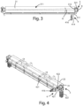
figure 3 shows a top view of the calibrating roller of the machine infigure 1 ; -
figure 4 shows a perspective view offigure 2 ; -
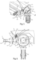
figure 5 shows a perspective view of the cleaning assembly of the machine offigure 1 ; -
figure 6 shows a front view of the cleaning assembly offigure 5 ; and -
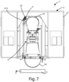
figure 7 shows a front view of a machine according to the present invention in the abrasive belt change configuration. - In the various figures the similar parts will be indicated with the same numerical references.
- Referring to
figures 1 - 6 , a sanding machine for sanding panels P is shown, wholly indicated with thereference 1. - Said
sanding machine 1 for sanding panels comprises asupport frame 2, anabrasion unit 3, arranged in saidsupport frame 2, and acleaning assembly 4 operatively coupled to saidabrasion unit 3. - The
support frame 2 of themachine 1, comprises acontainment casing 21, which in turn comprises aninternal hood 22, for the protection of saidabrasion unit 3 and for the containment of any chips or dust that may be projected during machining. - In the present embodiment, the
abrasion unit 3 includes acalibrating roller 31, arranged under saidhood 21, which protects it. Said calibratingroller 31 rotates around a rotation axis R, the position of which, as will be better described below, is adjustable. The calibratingroller 31 has a cylindrical shape and has alateral surface 311. - The
abrasion unit 3 also comprises adjustment means 32, in turn having abearing box 321, mechanically connected to arotation pin 312 of thecalibrating roller 31, not visible in the figures. Saidrotation pin 312 of thecalibrating roller 31 is in fact an end of the axis, on which said calibratingroller 31 rotates and which is evidently arranged on the rotation axis R. - The
bearing box 321 can be operated by apneumatic cylinder 322. The adjustment means 32 allow, through the operation of thegear box 32 by thepneumatic cylinder 322, the adjustment of the position of thepin 312 of thecalibrating roller 31, and therefore of the axis of rotation R. As can be seen in particular infigure 3 , said rotation axis R can be moved along a solid angle α, which, in the embodiment, is equal to ± 0.86°, allowing a maximum excursion of thecalibrating roller 31 of even 60-100 mm. - The
abrasion unit 3 also comprises abelt tensioning roller 34, arranged below thecalibrating roller 31, having a fixed rotation axis arranged substantially parallel to the rotation axis R of thecalibrating roller 31. - Finally, the
abrasion unit 3 includes anabrasive belt 33, partially wrapped both on theexternal surface 311 of thecalibrating roller 31 and on the external surface of thetensioning roller 34. - Generally, the
belt tensioning roller 34 is rotated by a motor (not shown in the figures), so as to also rotate thecalibrating roller 31 and theabrasive belt 33. Theabrasive belt 33 is then put in contact with, for example, the panel P to be machined, which is moving under saidtensioning roller 34 in an advancement direction A. - The
cleaning assembly 4 comprises an adjustment unit 41 and a blowingunit 42. The adjustment unit 41 comprises afixed element 411, fixed by means ofscrews 412 to thesupport frame 2, and in particular to a lateral edge of thehood 21. Saidfixed element 411 has aguide 413, oriented substantially perpendicular to the axis of rotation of thetensioning roller 34. - The adjustment unit 41 also comprises a
movable member 414, which in the present embodiment is a piston, mobile along saidguide 413, so as to be slidably movable within it. Thepiston 414, has its end facing theexternal surface 311 of thecalibrating roller 31, has afeeler 415, capable of assuming an operating position, in which it is extracted and in contact with theabrasive belt 33 or with an integral reference portion to thecalibrating roller 31, and a rest position, in which it is retracted and not in contact with theabrasive belt 33 or with said reference portion integral with thecalibrating roller 31. - In other embodiments said
movable member 414 can be a shuttle, a skate or the like. - The adjustment unit 41 also comprises an
actuator 416, for the pneumatic movement of saidpiston 414. Saidactuator 416 is preferably of the pneumatic type, such as an electric drive motor, but in other embodiments, other actuation systems ofpiston 414 can be provided. - The blowing
unit 42 comprises in the present embodiment asupport flange 421, fixed, on a portion, to saidpiston 414, and blowingmeans 422, fixed to saidsupport flange 421. Said blowingmeans 422 are suitable to emit a flow of compressed air, directed towards thelateral surface 311 of thecalibrating roller 31, to remove any residues from the sanding of the panels from theabrasive belt 33. - In the present embodiment, the
blowing means 422 are one or two hollow barrels orducts 422, arranged aligned substantially parallel to said rotation axis R of saidcalibrating roller 31. - Said
ducts 422 are connected to a source of compressed air and have lateral holes, on which nozzles are installed (not visible in the figures), facing thelateral surface 311 of thecalibrating roller 31. - The operation of the
sanding machine 1 described above is as follows. - When a change of
abrasive belt 33 is carried out, since saidabrasive belts 33 can also have a width of up to 2200 mm, they can present tapers. Therefore, when they are arranged between the calibratingroller 31 and thebelt tension roller 34, theabrasive belt 33 may not carry out correct abrasion on the panel P if not correctly tensioned. - In this case, the adjustment means 32 are suitable for moving the position of the rotation axis R of the calibrating
roller 31, with a positioning stroke, as mentioned, of up to 60-100 mm, being able to position theabrasive belt 33, i.e., the calibratingroller 31, in two working positions even distant from each other. - When the calibrating
roller 31, and in particular its rotation axis R, is moved by the adjustment means 32 and in particular by thebearing box 321 suitably moved by saidpneumatic cylinder 322, thepiston 414 is moved by said drivingmotor 416 so that thefeeler 415 remains in contact with theabrasive belt 33 or with the reference portion integral with the calibratingroller 31. - At the same time, following the movement of said
piston 414, the blowingunit 42 is translated, maintaining the distance between theducts 422, and in particular between the nozzles installed on them, and thelateral surface 311 of the calibratingroller 31, guaranteeing optimal cleaning of theabrasive belt 33 during the use, i.e. while it is moved by saidbelt tensioning roller 34. In particular, the compressed air passing through theducts 422 exits through the nozzles applied to theducts 422 themselves, interacting with the surface of theabrasive belt 33. - The
feeler 415 is kept at a constant distance from theabrasive belt 33 by means of theactuator 416. This contact is ensured by an appropriate control unit (not shown in the figure), which controls theactuator 416. - When it is necessary to replace the
abrasive belt 33, said control unit always moves saidfeeler 415 from said operating position to said rest position, in which saidfeeler 415 is retracted, as shown infigure 7 . - An advantage of the machine according to the following invention is that it allows optimal cleaning of the abrasive belt.
- It is also an advantage of the present invention that it allows the possibility of installing a cleaning assembly according to the invention in a sanding machine.
- A further advantage of the present invention is that of adapting the position of the cleaning assembly according to the position of the calibrator roller.
- The present invention has been described for illustrative but not limitative purposes, according to its preferred embodiments, but it is to be understood that modifications and/or changes can be introduced by those skilled in the art without departing from the relevant scope as defined in the enclosed claims.
Claims (11)
- Sanding machine (1)for sanding panels (P), such as panels made of wood, fiberglass, plastic, metal, and the like, comprisingan abrasion unit (3) for abrading said panel (P) using an abrasive belt (33), anda cleaning assembly (4), having a blowing unit (42), for cleaning said abrasive belt (33),characterized in that said cleaning assembly (4) comprises an adjustment unit (41), configured to maintain said blowing unit (42) at a predefined distance from said abrasive belt (33).
- Sanding machine (1) according to the preceding claim, characterized in that it comprises a feeler (415), capable of assuming an operating position, wherein it is in contact with the abrasive belt (33) or with a reference integral with the calibrating roller (31), and a rest position.
- Sanding machine (1) according to any one of the preceding claims, characterized in that when said feeler (415) is extracted when, it is in said operative position, while when it is in said rest position, it is retracted.
- Sanding machine (1) according to any one of the preceding claims, characterizedin that it comprises a support frame (2),in that said cleaning assembly (4) comprises:a fixed element (411), fixed to said support frame (2), wherein said fixed element (411) has a guide (413); anda movable member (414), movable in said guide (413),wherein said feeler (415) is arranged on said movable member (414); andin that said blowing unit (42) is fixed to said movable member (414).
- Sanding machine (1) according to the preceding claim, characterized in that said movable member is a piston (414).
- Sanding machine (1) according to any one of claims 4 or 5, characterized in that said blowing unit (42) comprisesa support flange (421), fixed to said movable member (414), andblowing means (422), fixed to said support flange (421), capable of emitting a flow of compressed air towards the lateral surface (311) of said calibrating roller (31), to remove the sanding residues of said panel (P) from said abrasive belt (33).
- Sanding machine (1) according to the preceding claim, characterizedin that said blowing means (42) comprise at least one duct (422), which can be connected to a source of compressed air,wherein said at least one duct (422) has one or more lateral holes, on which nozzles are installed for the release of the compressed air, wherein said nozzles are directed towards said abrasive belt (33).
- Sanding machine (1) according to any one of the preceding claims, characterized in that said abrasion unit (3) comprisesa calibrating roller (31), having a rotation axis (R),a tensioner roller (34), arranged below said calibrating roller (31), wherein said abrasive belt is arranged between said calibrating roller (31) and said tensioner roller (34), andadjustment means (32), for adjusting the position of said rotation axis (R) of said calibrating roller (31).
- Cleaning assembly (4), comprisinga blowing unit (42), for cleaning an abrasive belt (33), andan adjustment unit (41), configured to keep said blowing unit (42) at a predefined distance from said abrasive belt (33).
- Cleaning assembly (4) according to claim 9, characterized in that it comprises a feeler (415), capable of assuming an operating position, wherein it is extracted and in contact with the abrasive belt (33) or with a reference integral with the calibrating roller (31), and a rest position, wherein it is retracted.
- Cleaning assembly (4) according to any one of claims 9 or 10, characterizedin that it comprisesa fixed element (411), having a guide (413), anda movable member (414), movable in said guide (413),wherein said feeler (415) is arranged on said movable member (414); andin that said blowing unit (42) is fixed to said movable member (414).
Applications Claiming Priority (1)
| Application Number | Priority Date | Filing Date | Title |
|---|---|---|---|
| IT102022000026811A IT202200026811A1 (en) | 2022-12-23 | 2022-12-23 | Machine for sanding panels and cleaning of this machine |
Publications (1)
| Publication Number | Publication Date |
|---|---|
| EP4389348A1 true EP4389348A1 (en) | 2024-06-26 |
Family
ID=85462218
Family Applications (1)
| Application Number | Title | Priority Date | Filing Date |
|---|---|---|---|
| EP23215776.8A Pending EP4389348A1 (en) | 2022-12-23 | 2023-12-12 | Machine for sanding panels and cleaning assembly of such machine |
Country Status (2)
| Country | Link |
|---|---|
| EP (1) | EP4389348A1 (en) |
| IT (1) | IT202200026811A1 (en) |
Cited By (1)
| Publication number | Priority date | Publication date | Assignee | Title |
|---|---|---|---|---|
| CN120347636A (en) * | 2025-06-23 | 2025-07-22 | 中国机械工业建设集团有限公司 | Steel construction terminal surface grinding device |
Citations (3)
| Publication number | Priority date | Publication date | Assignee | Title |
|---|---|---|---|---|
| US4109422A (en) * | 1976-04-05 | 1978-08-29 | Parsons Enterprises, Inc. | Sander cleaning process |
| JPH07256550A (en) * | 1994-03-23 | 1995-10-09 | Amitec Corp | Belt sander and cleaning of sanding belt |
| US20070259608A1 (en) * | 2006-05-03 | 2007-11-08 | Bechtold Michael J | Method and apparatus for precision polishing of optical components |
-
2022
- 2022-12-23 IT IT102022000026811A patent/IT202200026811A1/en unknown
-
2023
- 2023-12-12 EP EP23215776.8A patent/EP4389348A1/en active Pending
Patent Citations (3)
| Publication number | Priority date | Publication date | Assignee | Title |
|---|---|---|---|---|
| US4109422A (en) * | 1976-04-05 | 1978-08-29 | Parsons Enterprises, Inc. | Sander cleaning process |
| JPH07256550A (en) * | 1994-03-23 | 1995-10-09 | Amitec Corp | Belt sander and cleaning of sanding belt |
| US20070259608A1 (en) * | 2006-05-03 | 2007-11-08 | Bechtold Michael J | Method and apparatus for precision polishing of optical components |
Cited By (1)
| Publication number | Priority date | Publication date | Assignee | Title |
|---|---|---|---|---|
| CN120347636A (en) * | 2025-06-23 | 2025-07-22 | 中国机械工业建设集团有限公司 | Steel construction terminal surface grinding device |
Also Published As
| Publication number | Publication date |
|---|---|
| IT202200026811A1 (en) | 2024-06-23 |
Similar Documents
| Publication | Publication Date | Title |
|---|---|---|
| EP4061578B1 (en) | Belt sanding head | |
| RU2755910C2 (en) | Method for partial surface grinding and grinding device for implementing this method | |
| KR102171939B1 (en) | Plasma cutting apparatus | |
| KR102689448B1 (en) | Automatic buffing apparatus of cylinder inner surface | |
| US20180311785A1 (en) | A grinding module, a grinding machine and a method for grinding | |
| EP3160673A1 (en) | Wire shaping machine for cutting blocks of natural stone material | |
| US8943934B2 (en) | Apparatus and method for removing board edge waste strips in a ripsawing operation | |
| KR101661926B1 (en) | Cutting Device | |
| KR20220041654A (en) | Deburring apparatus | |
| EP0879677B1 (en) | A planing machine | |
| FI123813B (en) | Method and apparatus for grinding a cylindrical workpiece | |
| FI71508C (en) | ANORDNING FOER SLIPNING AV TORKSYLINDERN HOS EN PAPPERSMASKIN. | |
| EP3827950B1 (en) | Machine for machining panels | |
| IT202200026811A1 (en) | Machine for sanding panels and cleaning of this machine | |
| US4893661A (en) | Drive belt tension control apparatus for inverted rooter | |
| US4346536A (en) | Tilting arbor belt sander | |
| EP3566840B1 (en) | Operating head for machines for the processing of components made of wood or the like | |
| CN219767925U (en) | Automatic sand blasting device | |
| EP1660284B1 (en) | Method and apparatus for crowning band saw pulley wheels | |
| ITMO20100054A1 (en) | CUTTING MACHINE FOR LASTRIFORMS, PARTICULARLY FOR CUTTING CERAMIC TILES, NATURAL AND SIMILAR STONES | |
| US2749675A (en) | Abrasive grinding machines | |
| CN209598898U (en) | A floating primer sander | |
| EP3842198A1 (en) | Moving system for moving a roller for working or cleaning a piece | |
| KR20170131561A (en) | A grinding machine and method for machining an awn edge of a rotor blade | |
| KR100920069B1 (en) | Flexible splitting device for textile coded paper topped with rubber |
Legal Events
| Date | Code | Title | Description |
|---|---|---|---|
| PUAI | Public reference made under article 153(3) epc to a published international application that has entered the european phase |
Free format text: ORIGINAL CODE: 0009012 |
|
| STAA | Information on the status of an ep patent application or granted ep patent |
Free format text: STATUS: THE APPLICATION HAS BEEN PUBLISHED |
|
| AK | Designated contracting states |
Kind code of ref document: A1 Designated state(s): AL AT BE BG CH CY CZ DE DK EE ES FI FR GB GR HR HU IE IS IT LI LT LU LV MC ME MK MT NL NO PL PT RO RS SE SI SK SM TR |
|
| STAA | Information on the status of an ep patent application or granted ep patent |
Free format text: STATUS: REQUEST FOR EXAMINATION WAS MADE |
|
| 17P | Request for examination filed |
Effective date: 20241203 |
|
| RBV | Designated contracting states (corrected) |
Designated state(s): AL AT BE BG CH CY CZ DE DK EE ES FI FR GB GR HR HU IE IS IT LI LT LU LV MC ME MK MT NL NO PL PT RO RS SE SI SK SM TR |
|
| STAA | Information on the status of an ep patent application or granted ep patent |
Free format text: STATUS: EXAMINATION IS IN PROGRESS |
|
| 17Q | First examination report despatched |
Effective date: 20250206 |