EP4389335A1 - Method for wire electrical discharge machining - Google Patents
Method for wire electrical discharge machining Download PDFInfo
- Publication number
- EP4389335A1 EP4389335A1 EP22216266.1A EP22216266A EP4389335A1 EP 4389335 A1 EP4389335 A1 EP 4389335A1 EP 22216266 A EP22216266 A EP 22216266A EP 4389335 A1 EP4389335 A1 EP 4389335A1
- Authority
- EP
- European Patent Office
- Prior art keywords
- wire
- wire electrode
- current
- value reflecting
- machining
- Prior art date
- Legal status (The legal status is an assumption and is not a legal conclusion. Google has not performed a legal analysis and makes no representation as to the accuracy of the status listed.)
- Granted
Links
Images




Classifications
-
- B—PERFORMING OPERATIONS; TRANSPORTING
- B23—MACHINE TOOLS; METAL-WORKING NOT OTHERWISE PROVIDED FOR
- B23H—WORKING OF METAL BY THE ACTION OF A HIGH CONCENTRATION OF ELECTRIC CURRENT ON A WORKPIECE USING AN ELECTRODE WHICH TAKES THE PLACE OF A TOOL; SUCH WORKING COMBINED WITH OTHER FORMS OF WORKING OF METAL
- B23H7/00—Processes or apparatus applicable to both electrical discharge machining and electrochemical machining
- B23H7/02—Wire-cutting
- B23H7/08—Wire electrodes
-
- B—PERFORMING OPERATIONS; TRANSPORTING
- B23—MACHINE TOOLS; METAL-WORKING NOT OTHERWISE PROVIDED FOR
- B23H—WORKING OF METAL BY THE ACTION OF A HIGH CONCENTRATION OF ELECTRIC CURRENT ON A WORKPIECE USING AN ELECTRODE WHICH TAKES THE PLACE OF A TOOL; SUCH WORKING COMBINED WITH OTHER FORMS OF WORKING OF METAL
- B23H3/00—Electrochemical machining, i.e. removing metal by passing current between an electrode and a workpiece in the presence of an electrolyte
Definitions
- the invention relates generally to a method for determining or monitoring the condition of a wire electrode used in a fastwire cutting machine. Moreover, the invention relates to a method for controlling a fastwire machining process in consideration of the present condition of the wire electrode, in particular the wire electrode wearing condition.
- fastwire machines a.k.a. high-speed wire electrical discharge machines, HS-WEDM, reciprocating WEDM
- the typically molybdenum wire electrode travels at about 10m/s.
- the fastwire machining takes place in a conductive fluid (electrolyte).
- the fluid is typically carried to the gap by means of nozzles coaxial to the wire.
- the wire traveling at high speed drags the fluid into the gap.
- the discharge pulses used in a fastwire process are much longer than WEDM discharge pulses, causing less wire wearing.
- molybdenum wire used in fastwire process has a high evaporation temperature, which again makes it less subject to wearing.
- the high wire traveling speed reduces the thermal load per length unit of the active wire section.
- the molybdenum wire can be used thousands of times. For this reason it is made to reciprocate, i.e. move back and forth between two wire drums (as shown exemplarily in Figure 3 ), or more typically, using an individual wire drum which unwinds the wire at one side, and then rewinds the wire on the other side of said drum, once the wire has traveled through the wire traveling circuit (as shown exemplarily in Figure 1 ). Still, there is a degradation of the wire electrode over time.
- a 0.20mm molybdenum wire should be replaced when the residual thickness is about 0.14mm or earlier, to avoid the risk of sudden wire breakage. Wear is typically directional; this means that the wire is somehow flattened on the erosion side. Strictly speaking, the residual thickness of the used wire does not correspond to a diameter. However the residual thickness can be used to monitor the wire wearing because the difference provides a safety margin. However, since wearing depends on the particular machining, on the workpiece material, on the machining parameter settings, flushing condition, etc., service life of the wire electrode cannot always be predicted adequately.
- this machine features a wire electrode traveling horizontally, a rotatory table to turn the baseplate upside-down while cutting, and a collecting tray to orderly collect the parts separated from a baseplate.
- the purpose is increasing the degree of automation in an additive parts production process.
- the separation process is conducted in an electrolyte bath to ensure the safe flushing of the kerf, which in case of horizontal traveling wire electrode is more critical than with vertical traveling wire.
- CN109822169A discloses a fastwire machine having a tensioning adjustment mechanism, by which the wire tension is reduced when the wire diameter is reduced due to wearing.
- the wire circuit includes a wire diameter measuring mechanism for measuring the diameter of the molybdenum wire.
- the wire diameter is measured by means of an ultrasonic distance measuring sensor, or a laser distance measuring sensor or an infrared distance measuring sensor.
- CN206578396U discloses a fastwire machine embedding a molybdenum wire monitoring system, to detect the degree of wear of the wire in real time.
- the monitoring system consists of a digital micrometer and a feedback circuit.
- the diameter of the filament is thus measured directly, by means of a dedicated sensor.
- Optical wire diameter measuring devices are well known and used for instance in the wire drawing process. They are very fast and accurate, and even very small defects can be identified in-process, with the wire drawn at high speed.
- a problem with optical wire diameter measuring devices is that they are sensitive to dirt.
- optical sensors add costs and complexity to the machine.
- Mechanical gauging means are generally excluded for the same reasons and other drawback.
- JPS61209819A discloses a method for the detection of a wire diameter in a machining area and for the detection of a current feeding condition in a wire electrical discharge machine.
- the condition of the wire electrode is detected by measuring a current which flows in a loop including the wire portion between the upper and the lower current feeder.
- the measurement is made between an upper- and the lower current feeder; the resistance of a wire section with progressively narrowing cross-section is measured.
- the distance between the upper- and the lower current feeder is comparably short, and said distance changes with the setting of Z-axis position which is a function of the workpiece thickness.
- the present invention discloses a method for the detection of the condition of a wire electrode, for use with a fastwire cutting process, which is also called as fastwire EDM cutting process.
- the method is used to detect the condition of a fresh- and/or used wire electrode.
- the method is used to determine the wearing condition of the deployed wire electrode.
- a first aspect of the present invention is thus directed to a method for the identification of the condition of the wire electrode deployed in a fastwire machine by an electrical measurement of a value reflecting the electrical impedance of a segment of said wire electrode.
- the invention refers to a method for determining a condition of a wire electrode deployed in a fastwire cutting machine comprising a wire traveling circuit in which the wire travels back- and forth, with a first- and a second wire guiding head by which the wire electrode is guided and positioned in relation to a workpiece laying between these wire guiding heads, whereas the wire electrode is in contact with a first- and a second electrical contact, both contacts being located on said wire traveling circuit, whereas a value reflecting the electrical impedance of a wire electrode segment between the first electrical contact and the second electrical contact is measured, whereas the measurement of said wire electrode segment L is conducted in a dry state and the condition of the wire electrode is derived from the measured value reflecting the electrical impedance of said wire electrode segment L.
- the measurement of the wire electrode segment L is thus conducted in a dry state.
- the identification of the condition includes primarily a wearing status of the deployed wire electrode, which is proportional to its cross section, which in turn is proportional to the electrical impedance of the conductor.
- the identification may further include a wire electrode type, the wire electrode diameter, and the appraisal of the quality of a fresh unused wire.
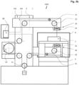
- FIG. 1 is a simplified illustration showing the relevant parts of a typical fastwire EDM machine 1001, which has flushing nozzles to feed the electrolyte to the cutting kerf, but this machine has no bath.
- the wire traveling circuit comprises a wire drum 10, a plurality of pulleys, and a wire tensioning unit 11.
- the wire electrode is unwound and transported from a wire drum 10 to the machining area and back to the same wire drum 10, where it is recoiled. Then, the wire traveling direction is inverted, and the machining continues with the wire traveling back and forth.
- Several hundred meters of wire electrode are coiled on the wire drum 10.
- a predetermined tensioning force is impressed to the wire by means of the wire tensioning unit 11.
- the workpiece 2 is mounted on a table 6, and a pan 7 collects the electrolyte used in the fastwire cutting process.
- the electrolyte is provided by means of the nozzles 23, 33 and is dragged into the kerf by the wire.
- the wire electrode 1 is guided by a wire guide 22 located in the upper wire guiding head 20, and by a wire guide 32 located in the lower wire guiding head 30.
- the current feeding members 21 and 31 serve to feed the machining current to the traveling wire electrode 1.
- the traveling wire electrode 1 is positioned relatively to the workpiece 2 by means of said guiding heads 20, 30, and is moved according to a machining program to generate the desired part.
- FIG 2a shows schematically a fastwire machine 1002, which is very similar to the one depicted in figure 1 , but this one operates in a submerged mode. It has a worktank 8, which is filled with the machining fluid 5.
- the machining fluid used with fastwire machines is an electrolyte having a conductivity of around 3mS/cm.
- Figure 2b shows the same fastwire machine 1002, in which the Worktank 8 was drained, and thus the electrolyte level 5 is low.
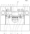
- FIG. 3 shows schematically another fastwire machine 1003, which operates in submerged mode.
- the wire electrode 1 travels horizontally.
- the wire is guided in the machining area by means of the wire guiding heads, in particular a left wire guiding head 120 and a right wire guiding head 130.
- the wire is made to travel back and forth between two wire drums 110 and 111, by which the amount of wire electrode stored can be increased massively.
- This exemplary machine has a rotary axis 210 to rotate a baseplate 4 bearing the additively manufactured parts to be separated by means of the fastwire cutting process.
- fastwire machines use a molybdenum wire electrode, so that there is comparably low wear.
- the fastwire machine is operated in a reciprocating mode and the same wire electrode is reused many times. In this way, the fastwire machine can work for several tens of hours.
- the wire electrode 1 is still subject to wear due to the high energy of the discharges occurring between the wire 1 and the workpiece 2.
- the initial cross-section of the unused wire reduces continuously with the progress of machining by the action of discharges.
- the wire wearing over time can be uneven, and also if the machining produces a substantially even wear, this wear still depends on the current machining task and cutting conditions.
- determining the reduction in wire diameter or more generally, a value reflecting the cross section and thus the condition of the wire electrode is very useful for the safe operation of the system and for the optimal use of the wire.
- the condition of a wire electrode deployed in a fastwire machine is determined.
- the machine comprises a wire traveling circuit with a first- and a second wire guiding head by which the wire electrode is guided and positioned in relation to a workpiece laying between these wire guiding heads.
- the condition of the wire electrode is determined by the fact that the wire electrode is in contact with a first- and a second electrical contact, both contacts being located along of the wire traveling circuit, and that a value reflecting an electrical impedance Z L of a wire electrode segment L between the first electrical contact and the second electrical contact is measured, whereas the measurement of said wire electrode segment L is conducted in a dry state, and that the condition of the wire electrode is derived from the measured value reflecting the electrical impedance Z L of said wire electrode segment L.
- a value reflecting the electrical impedance of an unused wire electrode and/or a value reflecting the electrical impedance of an exhausted wire electrode is pre-stored in a database, or is determined by measurement and stored in the database, for one or more wire electrodes types and/or a wire electrode diameter.
- an unused wire electrode is a new wire electrode.
- an exhausted wire electrode is a wire electrode which, by definition, is at its wire wearing limit.
- the database with the pre-stored items is provided by the machine tool manufacturer.
- the database which may be local or remote, may include reference value reflecting the electrical impedance of a plurality of wire electrodes of different diameter, type, composition and/or structure. Wire electrode database items including reference value reflecting the electrical impedance are thus pre-stored, so that they are available to the control unit for further use.
- the value reflecting the electrical impedance of an unused wire electrode and/or the value reflecting the electrical impedance of an exhausted wire electrode is measured and stored in the database.
- the value reflecting the electrical impedance of an unused wire electrode is measured immediately after the installation of a new molybdenum wire in the wire traveling circuit, and while no machining is performed.
- the measured value of the electrical impedance is stored with additional information, such as wire diameter, wire type, composition and structure, manufacturer, production date, date of first use of the wire spool, etc..
- additional information such as wire diameter, wire type, composition and structure, manufacturer, production date, date of first use of the wire spool, etc.
- Certain data can be automatically retrieved by the fastwire machine, for instance from an RFID chip stuck on the wire spool, or are transcribed manually.
- the measurement it is possible to collect reference values reflecting the impedance of a deployed wire electrode, for instance of a wire electrode having unknown electrical impedance.
- the value reflecting the electrical impedance of an exhausted wire electrode is determined by measurement in dedicated experiments and stored in the database.
- the reference value reflecting the electrical impedance of an exhausted wire electrode can also be determined roughly, in a simplified way, by multiplying the previously determined or known value reflecting the electrical impedance of an unused wire electrode by a factor, for instance 70%.
- a wearing condition of the deployed wire electrode is determined by comparing the measured value reflecting the electrical impedance of the currently deployed wire electrode with a reference value reflecting the electrical impedance
- the actual wearing condition of the deployed wire electrode is thus determined for a wire segment L between the first electrical contact and the second electrical contact by measuring the value reflecting the electrical impedance and by comparing said measured value with a known reference value reflecting the electrical impedance.
- a known reference value reflecting the electrical impedance.
- the reference value one can use the value reflecting the electrical impedance of a new, unused wire electrode of same type, e.g. multiplied by a factor 0.6 to determine a value reflecting the electrical impedance of an exhausted wire electrode.
- knowing e.g. the reference value reflecting the electrical impedance of an exhausted wire electrode one can determine the wearing status by computing the difference of the reference value with the measured value reflecting the electrical impedance of the deployed wire electrode; the end of life of the wire electrode is reached when the said difference is zero. In this way it is also possible to extrapolate how much time the fastwire machine can continue to operate with the currently deployed wire electrode, and to decide if the deployed wire electrode must be replaced to execute the next machining or not, etc.
- the residual machining time to full exhaust of the deployed wire electrode is estimated based on one or more measurements of the value reflecting the electrical impedance Z L .
- the residual wire electrode life is carried out after the execution of a first machining, and a wear rate of the deployed wire electrode is derived based on the difference of the initial value reflecting the electrical impedance (of a new wire electrode) and the measurement carried out after the first machining, in consideration of e.g. the machining time of the first machining.
- the process begins at step 300, with the setup of the machine.
- the impedance of the freshly deployed wire can be measured 302. Based on the measured value and the reference impedance of a new wire having the same type 301, it is determined if the initial value is within the tolerance 303. If the initial value is not in tolerance, the impedance measure circuit or the wire quality is checked 304. If the initial value is in tolerance, the start of machining 1 can be executed 305. After the end of the machining 1 shown in step 306, the impedance of the deployed wire at current machining time is measured again 307. The residual wire electrode life is computed 309 based on the measure value and the reference impedance of exhausted wire having the same type 308.
- step 309 it is determined if the machining 2 can be completed based on the computed residual wire electrode life and the estimated duration of the machining 2. If the computed residual wire electrode life is not sufficient to complete the machining 2, the spool replacement is executed 312. If the computed residual wire electrode life is sufficient to complete the machining 2, the machining 2 can be started 313 and completed as shown in the step 314.
- the value reflecting the impedance of the deployed wire electrode is compared with a reference value reflecting the impedance of the wire electrode at a wire wearing limit, and, when the comparison reveals that the wire electrode is exhausted, the control unit executes one or more of the following actions:
- a 0.20 mm molybdenum wire should be replaced when the residual thickness is about 0.14 mm or earlier, to avoid the risk of sudden wire breakage.
- the reference values reflecting the impedance at a wire wearing limit of the molybdenum wire electrodes of different size is stored in a database, and used for comparison with the value reflecting the impedance of the deployed wire electrode. A decision if and how to continue the fastwire process may be based on said comparison. An action may also be taken before the wire wear limit is reached, so that the current machining can be completed.
- the control unit of the machine tool or its user interface may release a warning message to inform the operator that the wire electrode must be replaced.
- the control unit may pause or stop the process to avoid a wire breaking, and resume after the replacement of the wire electrode by the operator. In future, the replacement of the wire electrode may be an automated process.
- the measurement of the electrical impedance of the currently deployed unused wire electrode is conducted before the machining start, whereas the determined condition of the deployed wire electrode is one of wire electrode type and/or a wire electrode diameter and/or the wire quality.
- the same system used to determine the wearing condition of the wire electrode deployed in the machining process can be used to determine the condition of the fresh wire electrode.
- the determined condition of the wire electrode is not the wire wearing condition, since the measurement is conducted with an unused wire electrode.
- the measurement of the electrical impedance of the unused wire serves to verify if the value for the deployed wire correspond to the expected nominal value.
- the measured electrical impedance may deviate, for example, because the wire type or diameter is wrong, or the quality of the wire electrode is not as expected, or the first- and/or the second electrical contact laying in a wire evacuation section of the wire traveling circuit is not working properly, etc.
- the user may get a warning message, and the machining may be paused, and the wire electrode may be replaced.
- the user may get further information and support to determine the reason for such deviation. This measurement is preferably conducted before the start of machining, once the wire is inserted in the wire traveling circuit, while the wire travels or while it is resting.
- the value reflecting the electrical impedance Z L is determined by applying a DC current signal having a defined value to the considered wire electrode segment L between the first- and the second electrical contact, and by measuring the voltage between these contacts, and/or by applying a DC voltage signal having a defined value to the considered wire electrode segment L between the first- and the second electrical contact, and by measuring the current between these contacts.
- the measured voltage is proportional to the electrical impedance Z L of the wire segment L.
- the measured current is proportional to the electrical impedance Z L of the wire segment L.
- the measured value reflecting the electrical impedance Z L e.g. the resistance R L of a measured wire electrode section L
- the measured value reflecting the electrical impedance Z L is proportional to the cross-sectional area of the deployed wire electrode 1, and therefore it is a meaningful value for assessing the state of wear of the wire.
- the measurement of the value reflecting the electrical impedance Z L the comparison with a stored reference value, e.g. comparison with the reference value reflecting the electrical impedance, reveals the condition of a used- or unused wire electrode.
- the value of an electrical resistance R L can be easily computed e.g. based on an applied current and a measured voltage, but said value of electrical resistance R L is not necessarily required to determine the condition of the wire electrode.
- the first- and a second electrical contact delimiting the wire electrode segment L to be measured may be located at an arbitrary position of the wire traveling circuit. It goes without saying that the contacts must be insulated with respect to each other, and generally also with respect to the machine body. In addition, in case of a fastwire machining with single wire drum, the measurement of the value reflecting the impedance is affected by the fact that there is a section of the wire circuit which is in parallel to the wire section L, i.e. the section of the wire circuit which includes the wire drum. This should be considered by placing the measuring contacts accordingly, or by correction of the measurements.
- the wire electrode traveling in the working area is surrounded by the electrically conductive electrolyte.
- the presence of the electrolyte in parallel to the wire electrode reduces the electrical impedance.
- the value reflecting the electrical impedance of the wire electrode segment L is measured in a dry state, so that the measured value is not affected by the presence of the electrolyte.
- said dry state is achieved by measuring the wire electrode segment L outside of the machining area, and/or by stopping the supply of a machining fluid through the flushing nozzles, and/or by draining or lowering the level of a machining fluid bath, and/or by moving the wire electrode out of the machining fluid bath.
- a "dry state” is achieved for instance by measuring the wire electrode segment L outside of the machining area, e.g. in a wire supply section or a wire evacuation section of the wire traveling circuit.
- the wire electrode is not in contact with the electrolyte, normally.
- the dry state may also be achieved in the machining area, if there is no electrolyte around the wire electrode or other conducting elements in contact or in proximity of the wire electrode.
- the wire electrode segment L to be measured may be located in the machining area, e.g. between the upper current feeder 21 and the lower current feeder 31, when the electrolyte is not supplied through the nozzles 23, 33.
- the measurement of the wire electrode segment L may be carried out at the upper portion of the wire traveling circuit, e.g. between the contact 125 and the upper current feeder 21, in a dry region. In this way, the electrolyte is not necessarily drained from the worktank.
- the figures 2a and 2b further shows the measuring circuit 50, for the measurement of a value reflecting the electrical impedance.
- Figure 4 is an exemplary measuring circuit to measure the value reflecting the electrical impedance of a wire electrode segment.
- Figure 4 shows a measuring loop for the example shown in figure 2a , and an exemplary measuring circuit for the measurement of the electrical impedance (e.g. resistance) of a currently monitored wire electrode segment L.
- a DC current signal I M is provided by the current source 51, and is applied at the measuring loop which comprises the leads 34 and 35, the upper current feeder 21, the measuring contact 125, and the wire segment L to be measured.
- a switch 52 is provided to open the measuring circuit.
- the switch of the measuring circuit is controlled by a control circuit 60.
- the switch is synced with the operation of the fastwire process.
- the switch controlling the measurement circuit is closed e.g. when the machine is paused or stopped.
- the measurement of the value reflecting the electrical impedance Z L of wire electrode segment L may still be carried out in the machining area, e.g. between the current feeders, but here the electrolyte 5 must first be drained from the worktank, or the electrolyte must be lowered at least to a level at which it is not in contact with the wire electrode, and the electrolyte flow around the wire electrode is stopped. In this way the measurement of the electrical impedance Z L of wire electrode segment L is conducted in a substantially dry portion of the wire traveling circuit, in a dry state, and the measurement is not affected by the electrolyte.
- FIG 2b shows the fastwire machine 1002 which can operate in submerged mode.
- the worktank 8 is drained and the electrolyte flushing flow is stopped.
- the measurement of wire electrode segment L is carried out between the upper current feeder 21 and the lower current feeder 31.
- the pulleys 23, 33 are used as power feeder and/or as measuring contacts the measurement of the electrical impedance Z L .
- the use of existing current feeders or pulleys as measuring contacts is of advantage, because no extra contacts are required.
- the residual electrolyte is removed from the electrode wire by one or more air nozzles and/or water nozzles and/or wipers deployed on the wire traveling circuit.
- the electrolyte may still adhere to the wire electrode after stopping the supply of the electrolyte by the nozzles. This may affect the measurement of value reflecting the electrical impedance.
- there is a device along the wire traveling circuit, to remove the residual electrolyte from the wire e.g. an air nozzle coaxial with the wire electrode.
- the at the end of a machining the supply of electrolyte is stopped, then the air supply is activated with the wire electrode still traveling back and forth, and lastly the electrode is stopped for the measurement of the value reflecting the electrical impedance of wire electrode segment L.
- the wire electrode and the workpiece are moved away from each other.
- the measurement is carried out with the wire electrode positioned at a distance from the workpiece, or when there is no workpiece mounted on the table 6 of the machine. This is to avoid an accidental contact with the workpiece while measuring, due to e.g. electrolyte droplets, machining debris, etc.. For this reason, according to an embodiment of the present invention, the wire electrode and the workpiece are moved away from each other for the measurement of the value reflecting the electrical impedance of wire electrode segment L.
- the measurement is carried out before a machining and/or thereafter, to avoid process interruptions.
- the fastwire machine can work for several tens of hours before the wire electrode is exhausted and needs to be replaced, because the molybdenum wire electrode wears very slowly.
- a typical fastwire cutting process may take anywhere from few minutes up to a few hours. Due to the low wearing the fastwire cutting process is not necessarily paused to carry out the measurement of the electrical impedance Z L , but the measurement may be carried out after each one or more cutting operation, when the flushing jet is anyway stopped, and/or the worktank is drained.
- the measurement can also be executed in the course of a process pause.
- an intermediate measurement may be carried out in case of a very long machining, or if disturbances occur in the course of the machining, since disturbances may be the origin of increased wire wearing.
- the value reflecting the impedance of the wire electrode is measured at the time when the wire traveling speed is zero. This is of advantage for the quality of the measurement, because in operation of a fastwire machine the wire traveling speed is very high.
- the average discharge current is controlled as a function of the measured wire wearing condition of the wire electrode.
- the average discharge current is controlled e.g. by adjusting the discharge frequency, or the current amplitude, or the pulse shape, or a combination thereof.
- the process is conducted by adjusting the average discharge current as a function of the measured wire wearing condition of the wire electrode. In this way the machining speed is increased without risk of wire breaking.
- At least one of the current feeders 21, 31 and the pulleys 23, 33 and the wire drum 10, 20, 30 is used as a contact for the measurement of the value reflecting the impedance of the wire electrode.
- the existing elements of the wire traveling circuit such as current feeders 21, 31 or existing pulleys 23, 33, or a wire drum 10, 20, 30, the number of additional components required for the measurement of the value reflecting the electrical impedance of the wire is limited. Moreover, the friction with the traveling wire is not increased by additional elements.
- the value reflecting the electrical impedance is the electrical resistance of the wire segment L.
- Said resistance is measured e.g. by applying a DC current pulse between the contacts and by measuring the resulting voltage, which according to Ohm's law depends only from the applied current and the resistance of wire segment L. If the deployed wire electrode type is unknown, the DC current pulse may be initially set to a low value and progressively raised. In this way a wire type and/or diameter is identified, using additional information available to the control unit, where required.
- the method according to the invention can be combined with other sensing methods, e.g. to improve the trustiness.
- other sensors can be used to determine the size of the fresh wire, e.g. the optical sensors used in the prior art.
- Additional characteristics of the wire electrode can be sensed and combined with the information provided by the invention, e.g. a wire temperature of a used wire.
- the method may be combined with wire wearing and/or a wire temperature derived from a model, e.g. a model based on the discharge pulse energy and discharge pulse frequency to derive a condition of the wire electrode, e.g. a wearing condition.
Landscapes
- Chemical & Material Sciences (AREA)
- Chemical Kinetics & Catalysis (AREA)
- Electrochemistry (AREA)
- Engineering & Computer Science (AREA)
- Mechanical Engineering (AREA)
- Electrical Discharge Machining, Electrochemical Machining, And Combined Machining (AREA)
Abstract
and that a value reflecting an electrical impedance ZL of the wire electrode segment L between the first electrical contact and the second electrical contact is measured. The measurement of said wire electrode segment L is conducted in a dry state, and that the condition of the wire electrode is derived from the measured value reflecting the electrical impedance ZL of said wire electrode segment L.
Description
- The invention relates generally to a method for determining or monitoring the condition of a wire electrode used in a fastwire cutting machine. Moreover, the invention relates to a method for controlling a fastwire machining process in consideration of the present condition of the wire electrode, in particular the wire electrode wearing condition.
- In so-called fastwire machines (a.k.a. high-speed wire electrical discharge machines, HS-WEDM, reciprocating WEDM), the typically molybdenum wire electrode travels at about 10m/s. In contrast to conventional wire electrical discharge machining which takes place in an insulating dielectric, i.e. oil or deionized water, the fastwire machining takes place in a conductive fluid (electrolyte). The fluid is typically carried to the gap by means of nozzles coaxial to the wire. The wire traveling at high speed drags the fluid into the gap. The discharge pulses used in a fastwire process are much longer than WEDM discharge pulses, causing less wire wearing. Moreover, molybdenum wire used in fastwire process has a high evaporation temperature, which again makes it less subject to wearing. Moreover, the high wire traveling speed reduces the thermal load per length unit of the active wire section. The molybdenum wire can be used thousands of times. For this reason it is made to reciprocate, i.e. move back and forth between two wire drums (as shown exemplarily in
Figure 3 ), or more typically, using an individual wire drum which unwinds the wire at one side, and then rewinds the wire on the other side of said drum, once the wire has traveled through the wire traveling circuit (as shown exemplarily inFigure 1 ). Still, there is a degradation of the wire electrode over time. For instance, a 0.20mm molybdenum wire should be replaced when the residual thickness is about 0.14mm or earlier, to avoid the risk of sudden wire breakage. Wear is typically directional; this means that the wire is somehow flattened on the erosion side. Strictly speaking, the residual thickness of the used wire does not correspond to a diameter. However the residual thickness can be used to monitor the wire wearing because the difference provides a safety margin. However, since wearing depends on the particular machining, on the workpiece material, on the machining parameter settings, flushing condition, etc., service life of the wire electrode cannot always be predicted adequately. - Recently, the fastwire machine AgieCharmilles Cut AM 500, specially dedicated to the separation of additively built parts from a baseplate was developed and offered on the market. As illustrated in
EP3360636A1 , this machine features a wire electrode traveling horizontally, a rotatory table to turn the baseplate upside-down while cutting, and a collecting tray to orderly collect the parts separated from a baseplate. The purpose is increasing the degree of automation in an additive parts production process. The separation process is conducted in an electrolyte bath to ensure the safe flushing of the kerf, which in case of horizontal traveling wire electrode is more critical than with vertical traveling wire. - The wearing of the wire electrode is an issue, because it limits the machining autonomy, and because it affects the productive and non-productive costs. In fact, replacing the wire electrode in fastwire machines is still a tedious manual operation. For this reason, it would be desirable to know the current state of the wire electrode, in particular its state of wear, possibly in a simple way.
- In practice one can pause the cutting process and measure the residual wire diameter, manually, to appraise the wearing state using e.g. a micrometric screw gauge, or simply cut until the wire is breaking. But this method is not efficient; it would be desirable to monitor the condition of the wire electrode without user intervention.
- Several methods for the determination of the wire diameter in a wire electrical discharge machine are known.
-
CN109822169A discloses a fastwire machine having a tensioning adjustment mechanism, by which the wire tension is reduced when the wire diameter is reduced due to wearing. The wire circuit includes a wire diameter measuring mechanism for measuring the diameter of the molybdenum wire. The wire diameter is measured by means of an ultrasonic distance measuring sensor, or a laser distance measuring sensor or an infrared distance measuring sensor. -
CN206578396U discloses a fastwire machine embedding a molybdenum wire monitoring system, to detect the degree of wear of the wire in real time. The monitoring system consists of a digital micrometer and a feedback circuit. - According to the two documents cited above, the diameter of the filament is thus measured directly, by means of a dedicated sensor. Optical wire diameter measuring devices are well known and used for instance in the wire drawing process. They are very fast and accurate, and even very small defects can be identified in-process, with the wire drawn at high speed. A problem with optical wire diameter measuring devices is that they are sensitive to dirt. However, in a fastwire machine it cannot be easily avoided, in particular in the machining area. Moreover, such optical sensors add costs and complexity to the machine. Mechanical gauging means are generally excluded for the same reasons and other drawback.
-
JPS61209819A - Thus there is need for a simple and reliable method by which the condition of the wire electrode can be monitored, to ensure a possibly uninterrupted machining process.
- It is an objective of this invention to provide a measuring method to overcome the drawbacks of the known methods. It is an objective of this invention to provide a simple, reliable and universal wire electrode measuring method and device for fastwire cutting process, to monitor the condition of the wire electrode, to ensure a machining process not interrupted by wire breaking, and to use the wire electrode up to the region of the wear limit.
- The present invention discloses a method for the detection of the condition of a wire electrode, for use with a fastwire cutting process, which is also called as fastwire EDM cutting process. In particular, the method is used to detect the condition of a fresh- and/or used wire electrode. Especially, the method is used to determine the wearing condition of the deployed wire electrode.
- A first aspect of the present invention is thus directed to a method for the identification of the condition of the wire electrode deployed in a fastwire machine by an electrical measurement of a value reflecting the electrical impedance of a segment of said wire electrode.
- More specifically, the invention refers to a method for determining a condition of a wire electrode deployed in a fastwire cutting machine comprising a wire traveling circuit in which the wire travels back- and forth, with a first- and a second wire guiding head by which the wire electrode is guided and positioned in relation to a workpiece laying between these wire guiding heads, whereas the wire electrode is in contact with a first- and a second electrical contact, both contacts being located on said wire traveling circuit, whereas a value reflecting the electrical impedance of a wire electrode segment between the first electrical contact and the second electrical contact is measured, whereas the measurement of said wire electrode segment L is conducted in a dry state and the condition of the wire electrode is derived from the measured value reflecting the electrical impedance of said wire electrode segment L.
- According to the present invention, the measurement of the wire electrode segment L is thus conducted in a dry state.
- According to the present invention, the identification of the condition includes primarily a wearing status of the deployed wire electrode, which is proportional to its cross section, which in turn is proportional to the electrical impedance of the conductor. Thus by measuring a value reflecting the electrical impedance of the wire electrode wearing status can be estimated. The identification may further include a wire electrode type, the wire electrode diameter, and the appraisal of the quality of a fresh unused wire.
- Further aspects are set forth in the dependent claims, the following description and the drawings. Other features are inherent in the methods and products disclosed or will become apparent to those skilled in the art from the following detailed description of embodiments and its accompanying drawings.
- Embodiments of the invention are now described, by way of example, and with reference to the accompanying drawings.
- FIG. 1
- a schematic of a fastwire EDM machine;
- FIG. 2a
- a schematic of the fastwire EDM machine for submerged operation, with a filled worktank;
- FIG. 2b
- a schematic of the fastwire machine for submerged operation, in which a worktank was drained;
- FIG. 3
- a schematic of a horizontal fastwire EDM machine for submerged operation;
- FIG. 4
- is an exemplary measuring circuit to measure the a value reflecting the electrical impedance of a wire electrode segment;
- Fig. 5
- is a flowchart to illustrate the monitoring of a deployed wire electrode.
-
Figure 1 is a simplified illustration showing the relevant parts of a typicalfastwire EDM machine 1001, which has flushing nozzles to feed the electrolyte to the cutting kerf, but this machine has no bath. In particular, the machine frame, the wire traveling circuit, and the machining area are represented. Generator, control unit, and electrolyte preparation unit are not shown. The wire traveling circuit comprises awire drum 10, a plurality of pulleys, and awire tensioning unit 11. The wire electrode is unwound and transported from awire drum 10 to the machining area and back to thesame wire drum 10, where it is recoiled. Then, the wire traveling direction is inverted, and the machining continues with the wire traveling back and forth. Several hundred meters of wire electrode are coiled on thewire drum 10. A predetermined tensioning force is impressed to the wire by means of thewire tensioning unit 11. Theworkpiece 2 is mounted on a table 6, and apan 7 collects the electrolyte used in the fastwire cutting process. The electrolyte is provided by means of thenozzles wire electrode 1 is guided by awire guide 22 located in the upperwire guiding head 20, and by awire guide 32 located in the lowerwire guiding head 30. Thecurrent feeding members traveling wire electrode 1. - The traveling
wire electrode 1 is positioned relatively to theworkpiece 2 by means of said guiding heads 20, 30, and is moved according to a machining program to generate the desired part. -
Figure 2a shows schematically afastwire machine 1002, which is very similar to the one depicted infigure 1 , but this one operates in a submerged mode. It has aworktank 8, which is filled with themachining fluid 5. The machining fluid used with fastwire machines is an electrolyte having a conductivity of around 3mS/cm.Figure 2b shows thesame fastwire machine 1002, in which theWorktank 8 was drained, and thus theelectrolyte level 5 is low. -
Figure 3 shows schematically anotherfastwire machine 1003, which operates in submerged mode. Here, opposite to the previous examples, thewire electrode 1 travels horizontally. The wire is guided in the machining area by means of the wire guiding heads, in particular a leftwire guiding head 120 and a rightwire guiding head 130. Moreover, the wire is made to travel back and forth between twowire drums rotary axis 210 to rotate abaseplate 4 bearing the additively manufactured parts to be separated by means of the fastwire cutting process. - As mentioned at the beginning, fastwire machines use a molybdenum wire electrode, so that there is comparably low wear. The fastwire machine is operated in a reciprocating mode and the same wire electrode is reused many times. In this way, the fastwire machine can work for several tens of hours. However, the
wire electrode 1 is still subject to wear due to the high energy of the discharges occurring between thewire 1 and theworkpiece 2. The initial cross-section of the unused wire reduces continuously with the progress of machining by the action of discharges. The wire wearing over time can be uneven, and also if the machining produces a substantially even wear, this wear still depends on the current machining task and cutting conditions. In this respect, determining the reduction in wire diameter or more generally, a value reflecting the cross section and thus the condition of the wire electrode is very useful for the safe operation of the system and for the optimal use of the wire. - According to the present invention, the condition of a wire electrode deployed in a fastwire machine is determined. The machine comprises a wire traveling circuit with a first- and a second wire guiding head by which the wire electrode is guided and positioned in relation to a workpiece laying between these wire guiding heads. The condition of the wire electrode is determined by the fact that the wire electrode is in contact with a first- and a second electrical contact, both contacts being located along of the wire traveling circuit, and that a value reflecting an electrical impedance ZL of a wire electrode segment L between the first electrical contact and the second electrical contact is measured, whereas the measurement of said wire electrode segment L is conducted in a dry state, and that the condition of the wire electrode is derived from the measured value reflecting the electrical impedance ZL of said wire electrode segment L.
- According to an embodiment of the invention, a value reflecting the electrical impedance of an unused wire electrode and/or a value reflecting the electrical impedance of an exhausted wire electrode is pre-stored in a database, or is determined by measurement and stored in the database, for one or more wire electrodes types and/or a wire electrode diameter.
- According to the present invention, an unused wire electrode is a new wire electrode. According to the present invention, an exhausted wire electrode is a wire electrode which, by definition, is at its wire wearing limit. Typically, the database with the pre-stored items is provided by the machine tool manufacturer. The database, which may be local or remote, may include reference value reflecting the electrical impedance of a plurality of wire electrodes of different diameter, type, composition and/or structure. Wire electrode database items including reference value reflecting the electrical impedance are thus pre-stored, so that they are available to the control unit for further use.
- According to an embodiment, the value reflecting the electrical impedance of an unused wire electrode and/or the value reflecting the electrical impedance of an exhausted wire electrode is measured and stored in the database. For example, the value reflecting the electrical impedance of an unused wire electrode is measured immediately after the installation of a new molybdenum wire in the wire traveling circuit, and while no machining is performed.
- Preferably, the measured value of the electrical impedance is stored with additional information, such as wire diameter, wire type, composition and structure, manufacturer, production date, date of first use of the wire spool, etc.. Certain data can be automatically retrieved by the fastwire machine, for instance from an RFID chip stuck on the wire spool, or are transcribed manually. By the measurement it is possible to collect reference values reflecting the impedance of a deployed wire electrode, for instance of a wire electrode having unknown electrical impedance.
- Typically, the value reflecting the electrical impedance of an exhausted wire electrode is determined by measurement in dedicated experiments and stored in the database.
- The reference value reflecting the electrical impedance of an exhausted wire electrode can also be determined roughly, in a simplified way, by multiplying the previously determined or known value reflecting the electrical impedance of an unused wire electrode by a factor, for instance 70%.
- According to an embodiment, a wearing condition of the deployed wire electrode is determined by comparing the measured value reflecting the electrical impedance of the currently deployed wire electrode with a reference value reflecting the electrical impedance
- of an unused wire electrode of same type, or
- of an exhausted wire electrode of same type.
- The actual wearing condition of the deployed wire electrode is thus determined for a wire segment L between the first electrical contact and the second electrical contact by measuring the value reflecting the electrical impedance and by comparing said measured value with a known reference value reflecting the electrical impedance. For the reference value one can use the value reflecting the electrical impedance of a new, unused wire electrode of same type, e.g. multiplied by a factor 0.6 to determine a value reflecting the electrical impedance of an exhausted wire electrode.
- Moreover, knowing e.g. the reference value reflecting the electrical impedance of an exhausted wire electrode, one can determine the wearing status by computing the difference of the reference value with the measured value reflecting the electrical impedance of the deployed wire electrode; the end of life of the wire electrode is reached when the said difference is zero. In this way it is also possible to extrapolate how much time the fastwire machine can continue to operate with the currently deployed wire electrode, and to decide if the deployed wire electrode must be replaced to execute the next machining or not, etc.
- According to another embodiment, the residual machining time to full exhaust of the deployed wire electrode is estimated based on one or more measurements of the value reflecting the electrical impedance ZL. Here, based on the known value reflecting the electrical impedance of the exhausted wire electrode and one or more measurements of the value reflecting the electrical impedance ZL of the partially used wire, one can estimate the residual wire electrode life and set the possible residual machining time accordingly. For instance, a measurement is carried out after the execution of a first machining, and a wear rate of the deployed wire electrode is derived based on the difference of the initial value reflecting the electrical impedance (of a new wire electrode) and the measurement carried out after the first machining, in consideration of e.g. the machining time of the first machining. One can estimate the residual wire electrode life e.g. by applying the same wear rate. As illustrated in
figure 5 , knowing the current wearing condition of the deployed wire electrode (residual wire electrode life) and at least roughly knowing the duration of a second machining, one can determine if it is possible to complete said second machining with the currently deployed wire electrode. Accordingly, the user may get a message with the request to replace the wire electrode, or the machine may execute another action, as discussed here below. - As shown in
figure 5 , the process begins atstep 300, with the setup of the machine. The impedance of the freshly deployed wire can be measured 302. Based on the measured value and the reference impedance of a new wire having thesame type 301, it is determined if the initial value is within thetolerance 303. If the initial value is not in tolerance, the impedance measure circuit or the wire quality is checked 304. If the initial value is in tolerance, the start ofmachining 1 can be executed 305. After the end of themachining 1 shown instep 306, the impedance of the deployed wire at current machining time is measured again 307. The residual wire electrode life is computed 309 based on the measure value and the reference impedance of exhausted wire having the same type 308. In thestep 309, it is determined if themachining 2 can be completed based on the computed residual wire electrode life and the estimated duration of themachining 2. If the computed residual wire electrode life is not sufficient to complete themachining 2, the spool replacement is executed 312. If the computed residual wire electrode life is sufficient to complete themachining 2, themachining 2 can be started 313 and completed as shown in thestep 314. - According to a further embodiment, the value reflecting the impedance of the deployed wire electrode is compared with a reference value reflecting the impedance of the wire electrode at a wire wearing limit, and, when the comparison reveals that the wire electrode is exhausted, the control unit executes one or more of the following actions:
- complete the current cut, the current machining or the current workpiece by using the current machining parameters,
- complete the current cut, the current machining or the current workpiece by using reduced machining parameters,
- release of a warning or alert message,
- pause or stop the current machining,
- replace the wire electrode.
- As mentioned in an earlier example, a 0.20 mm molybdenum wire should be replaced when the residual thickness is about 0.14 mm or earlier, to avoid the risk of sudden wire breakage. Preferably, the reference values reflecting the impedance at a wire wearing limit of the molybdenum wire electrodes of different size is stored in a database, and used for comparison with the value reflecting the impedance of the deployed wire electrode. A decision if and how to continue the fastwire process may be based on said comparison. An action may also be taken before the wire wear limit is reached, so that the current machining can be completed.
- In the fastwire process the wire wears very slowly, so that in general it is possible to finish the current operation for a short while when the wire is "exhausted". However, the wire should be replaced at the earliest opportunity to avoid wire breaking, damage to a workpiece and additional work to restore the operation. Thus, the control unit of the machine tool or its user interface may release a warning message to inform the operator that the wire electrode must be replaced. The control unit may pause or stop the process to avoid a wire breaking, and resume after the replacement of the wire electrode by the operator. In future, the replacement of the wire electrode may be an automated process.
- According to a further embodiment, the measurement of the electrical impedance of the currently deployed unused wire electrode is conducted before the machining start, whereas the determined condition of the deployed wire electrode is one of wire electrode type and/or a wire electrode diameter and/or the wire quality.
- In such embodiment, the same system used to determine the wearing condition of the wire electrode deployed in the machining process can be used to determine the condition of the fresh wire electrode. Here the determined condition of the wire electrode is not the wire wearing condition, since the measurement is conducted with an unused wire electrode. For instance, the measurement of the electrical impedance of the unused wire serves to verify if the value for the deployed wire correspond to the expected nominal value. The measured electrical impedance may deviate, for example, because the wire type or diameter is wrong, or the quality of the wire electrode is not as expected, or the first- and/or the second electrical contact laying in a wire evacuation section of the wire traveling circuit is not working properly, etc.
- If the measured value deviates substantially from an expected value, the user may get a warning message, and the machining may be paused, and the wire electrode may be replaced. The user may get further information and support to determine the reason for such deviation. This measurement is preferably conducted before the start of machining, once the wire is inserted in the wire traveling circuit, while the wire travels or while it is resting.
- According to a further embodiment, the value reflecting the electrical impedance ZL is determined by applying a DC current signal having a defined value to the considered wire electrode segment L between the first- and the second electrical contact, and by measuring the voltage between these contacts, and/or by applying a DC voltage signal having a defined value to the considered wire electrode segment L between the first- and the second electrical contact, and by measuring the current between these contacts.
- In the first case, by applying a defined DC current, the measured voltage is proportional to the electrical impedance ZL of the wire segment L. In the second case, by applying a defined DC voltage, the measured current is proportional to the electrical impedance ZL of the wire segment L.
- Assuming a substantially uniform wire wearing, the measured value reflecting the electrical impedance ZL, e.g. the resistance RL of a measured wire electrode section L, is proportional to the cross-sectional area of the deployed
wire electrode 1, and therefore it is a meaningful value for assessing the state of wear of the wire. Thus, knowing the nominal characteristics of the new deployed wire electrode, the measurement of the value reflecting the electrical impedance ZL, the comparison with a stored reference value, e.g. comparison with the reference value reflecting the electrical impedance, reveals the condition of a used- or unused wire electrode. It is noted that, the value of an electrical resistance RL can be easily computed e.g. based on an applied current and a measured voltage, but said value of electrical resistance RL is not necessarily required to determine the condition of the wire electrode. - The first- and a second electrical contact delimiting the wire electrode segment L to be measured may be located at an arbitrary position of the wire traveling circuit. It goes without saying that the contacts must be insulated with respect to each other, and generally also with respect to the machine body. In addition, in case of a fastwire machining with single wire drum, the measurement of the value reflecting the impedance is affected by the fact that there is a section of the wire circuit which is in parallel to the wire section L, i.e. the section of the wire circuit which includes the wire drum. This should be considered by placing the measuring contacts accordingly, or by correction of the measurements.
- In operation, the wire electrode traveling in the working area is surrounded by the electrically conductive electrolyte. The presence of the electrolyte in parallel to the wire electrode reduces the electrical impedance. Thus, according to the present invention, the value reflecting the electrical impedance of the wire electrode segment L is measured in a dry state, so that the measured value is not affected by the presence of the electrolyte.
- According to the present invention, said dry state is achieved by measuring the wire electrode segment L outside of the machining area, and/or by stopping the supply of a machining fluid through the flushing nozzles, and/or by draining or lowering the level of a machining fluid bath, and/or by moving the wire electrode out of the machining fluid bath.
- A "dry state" is achieved for instance by measuring the wire electrode segment L outside of the machining area, e.g. in a wire supply section or a wire evacuation section of the wire traveling circuit. Here the wire electrode is not in contact with the electrolyte, normally.
- However, the dry state may also be achieved in the machining area, if there is no electrolyte around the wire electrode or other conducting elements in contact or in proximity of the wire electrode. For instance, in case of the
fastwire machine 1001 offigure 1 operating in jet flushing mode, the wire electrode segment L to be measured may be located in the machining area, e.g. between the uppercurrent feeder 21 and the lowercurrent feeder 31, when the electrolyte is not supplied through thenozzles - In case of the
fastwire machine 1002 offigure 2b , which operates in submerged mode, the measurement of the wire electrode segment L may be carried out at the upper portion of the wire traveling circuit, e.g. between thecontact 125 and the uppercurrent feeder 21, in a dry region. In this way, the electrolyte is not necessarily drained from the worktank. - The
figures 2a and2b further shows the measuringcircuit 50, for the measurement of a value reflecting the electrical impedance. -
Figure 4 is an exemplary measuring circuit to measure the value reflecting the electrical impedance of a wire electrode segment.Figure 4 shows a measuring loop for the example shown infigure 2a , and an exemplary measuring circuit for the measurement of the electrical impedance (e.g. resistance) of a currently monitored wire electrode segment L. A DC current signal IM is provided by thecurrent source 51, and is applied at the measuring loop which comprises theleads current feeder 21, the measuringcontact 125, and the wire segment L to be measured. Aswitch 52 is provided to open the measuring circuit. For instance, the switch of the measuring circuit is controlled by acontrol circuit 60. The switch is synced with the operation of the fastwire process. The switch controlling the measurement circuit is closed e.g. when the machine is paused or stopped. When theswitch 52 is closed the measuring current provided by the current source flows through the measuring circuit, and a voltage UM is measured byvoltage measurement unit 53. The resistance RL of the wire segment L is computed according to ohm's law:
- In case of a fastwire machine operating in submerged mode, the measurement of the value reflecting the electrical impedance ZL of wire electrode segment L may still be carried out in the machining area, e.g. between the current feeders, but here the
electrolyte 5 must first be drained from the worktank, or the electrolyte must be lowered at least to a level at which it is not in contact with the wire electrode, and the electrolyte flow around the wire electrode is stopped. In this way the measurement of the electrical impedance ZL of wire electrode segment L is conducted in a substantially dry portion of the wire traveling circuit, in a dry state, and the measurement is not affected by the electrolyte. - An example hereto is shown in
figure 2b , which shows thefastwire machine 1002 which can operate in submerged mode. Theworktank 8 is drained and the electrolyte flushing flow is stopped. The measurement of wire electrode segment L is carried out between the uppercurrent feeder 21 and the lowercurrent feeder 31. In some embodiments thepulleys - According to an embodiment the residual electrolyte is removed from the electrode wire by one or more air nozzles and/or water nozzles and/or wipers deployed on the wire traveling circuit. The electrolyte may still adhere to the wire electrode after stopping the supply of the electrolyte by the nozzles. This may affect the measurement of value reflecting the electrical impedance. For this reason, according to the present embodiment there is a device along the wire traveling circuit, to remove the residual electrolyte from the wire, e.g. an air nozzle coaxial with the wire electrode. For instance, the at the end of a machining the supply of electrolyte is stopped, then the air supply is activated with the wire electrode still traveling back and forth, and lastly the electrode is stopped for the measurement of the value reflecting the electrical impedance of wire electrode segment L.
- According to an embodiment, the wire electrode and the workpiece are moved away from each other.
- Here, the measurement is carried out with the wire electrode positioned at a distance from the workpiece, or when there is no workpiece mounted on the table 6 of the machine. This is to avoid an accidental contact with the workpiece while measuring, due to e.g. electrolyte droplets, machining debris, etc.. For this reason, according to an embodiment of the present invention, the wire electrode and the workpiece are moved away from each other for the measurement of the value reflecting the electrical impedance of wire electrode segment L.
- Preferably, the measurement is carried out before a machining and/or thereafter, to avoid process interruptions.
- As mentioned earlier, the fastwire machine can work for several tens of hours before the wire electrode is exhausted and needs to be replaced, because the molybdenum wire electrode wears very slowly. A typical fastwire cutting process may take anywhere from few minutes up to a few hours. Due to the low wearing the fastwire cutting process is not necessarily paused to carry out the measurement of the electrical impedance ZL, but the measurement may be carried out after each one or more cutting operation, when the flushing jet is anyway stopped, and/or the worktank is drained.
- However, the measurement can also be executed in the course of a process pause. In particular, an intermediate measurement may be carried out in case of a very long machining, or if disturbances occur in the course of the machining, since disturbances may be the origin of increased wire wearing.
- According to another embodiment, the value reflecting the impedance of the wire electrode is measured at the time when the wire traveling speed is zero. This is of advantage for the quality of the measurement, because in operation of a fastwire machine the wire traveling speed is very high.
- According to a further embodiment, the average discharge current is controlled as a function of the measured wire wearing condition of the wire electrode.
- The average discharge current is controlled e.g. by adjusting the discharge frequency, or the current amplitude, or the pulse shape, or a combination thereof.
- The process is conducted by adjusting the average discharge current as a function of the measured wire wearing condition of the wire electrode. In this way the machining speed is increased without risk of wire breaking.
- According to an embodiment, at least one of the
current feeders pulleys wire drum - For instance, one may use the existing
pulley 23 as a first electrical contact andpulley 33 as the second electrical contact for the measurement. By using the existing elements of the wire traveling circuit such ascurrent feeders pulleys wire drum - According to an embodiment, the value reflecting the electrical impedance is the electrical resistance of the wire segment L. Said resistance is measured e.g. by applying a DC current pulse between the contacts and by measuring the resulting voltage, which according to Ohm's law depends only from the applied current and the resistance of wire segment L. If the deployed wire electrode type is unknown, the DC current pulse may be initially set to a low value and progressively raised. In this way a wire type and/or diameter is identified, using additional information available to the control unit, where required.
- It is understood that the method according to the invention can be combined with other sensing methods, e.g. to improve the trustiness. For instance, other sensors can be used to determine the size of the fresh wire, e.g. the optical sensors used in the prior art. Additional characteristics of the wire electrode can be sensed and combined with the information provided by the invention, e.g. a wire temperature of a used wire. In addition, the method may be combined with wire wearing and/or a wire temperature derived from a model, e.g. a model based on the discharge pulse energy and discharge pulse frequency to derive a condition of the wire electrode, e.g. a wearing condition.
-
- 1
- wire electrode
- 2
- workpiece
- 4
- baseplate
- 5
- electrolyte
- 6
- table
- 7
- electrolyte collecting pan
- 8
- work tank
- 10, 110, 111
- wire drum
- 11
- wire tensioning device
- 20, 30
- upper- and lower wire guiding head
- 34, 35
- leads
- 21, 31
- upper- and lower current feeder
- 121, 131
- left- and right current feeder
- 22, 32
- wire guide
- 34, 35
- lead
- 50
- impedance measuring circuit
- 51
- current source
- 52
- switch
- 53
- voltage measurement
- 60
- control circuit
- 120, 130
- left- and right wire guiding head
- 122-125
- measuring contacts
- 209
- dancer roll
- 300-314
- steps of method
- 1001-1003
- a fastwire machine
Claims (13)
- Method for determining a condition of a wire electrode (1) deployed in a fastwire cutting machine (1001, 1002, 1003), the fastwire cutting machine comprising a wire traveling circuit in which the wire travels back and forth, with a first- and a second wire guiding head by which the wire electrode is guided and positioned in relation to a workpiece laying between these wire guiding heads,
characterized in thatthe wire electrode is in contact with a first- and a second electrical contact, both contacts being located on the wire traveling circuit,and that a value reflecting an electrical impedance ZL of the wire electrode segment L between the first electrical contact and the second electrical contact is measured,whereas the measurement of said wire electrode segment L is conducted in a dry state, and that the condition of the wire electrode is derived from the measured value reflecting the electrical impedance ZL of said wire electrode segment L. - The method for determining a condition of a wire electrode according claim 1, characterized in that a reference value reflecting the electrical impedance of an unused wire electrode and/or an exhausted wire electrode is pre-stored in a database or is determined by measurement and stored in the database, for one or more wire electrodes types and/or a wire electrode diameter.
- The method for determining a condition of a wire electrode according to claim 1 or 2, characterized in that a wearing condition of the deployed wire electrode is determined by comparing the measured value reflecting the electrical impedance ZL with the reference value reflecting the electrical impedance- of an unused wire electrode of same type, or- of an exhausted wire electrode of same type.
- The method according to one of the preceding claims, characterized in that residual machining time to full exhaust of the deployed wire electrode is estimated based on one or more measurements of the value reflecting the electrical impedance ZL.
- The method according to one of the preceding claims, wherein the value reflecting the impedance of the wire electrode is compared with a reference value reflecting the impedance of the wire electrode at a wire wearing limit, and that, when the comparison reveals that the wire electrode is exhausted, the control unit executes one or more of the following actions:- complete the current cut, the current machining or the current workpiece by using the current machining parameters,- complete the current cut, the current machining or the current workpiece by using reduced machining parameters,- release of a warning or alert message,- pause or stop the current machining,- replace the wire electrode.
- The method according to one of the preceding claims, characterized in that the determined condition of the deployed wire electrode is one of:- the wire quality,- the wire type,- the wire diameter.
- The method according to one of the preceding claims, wherein the value reflecting the electrical impedance ZL is determined by:- applying a defined DC current signal having a defined value to the considered wire electrode segment L between the first- and the second electrical contact, and by measuring the voltage between the a first- and the second electrical contact, and/or- applying a defined DC voltage signal having a defined value to the considered wire electrode segment L between the first- and the second electrical contact, and by measuring the current between the a first- and the second electrical contact.
- Method according to one of the preceding claims, wherein said dry state is achieved by:- stopping the supply of a machining fluid through the flushing nozzles, and/or- draining or lowering the level of a machining fluid bath, and/or- moving the wire electrode out of the machining fluid bath.
- The method according to one of the preceding claims, characterized in that the residual electrolyte is removed from the electrode wire by one or more air nozzles and/or water nozzles and/or wipers deployed on the wire traveling circuit.
- The method according to one of the preceding claims, characterized in that the wire electrode and the workpiece are moved away from each other.
- The method according to one of the preceding claims, characterized in that the value reflecting the electrical impedance ZL of the wire electrode is measured at a time when the wire traveling speed is zero.
- The method according to one of the preceding claims, characterized in that the average discharge current is controlled as a function of the measured wire wearing condition of the wire electrode.
- The method according to one of the preceding claims, characterized in that at least one of the current feeders (21, 31) and the pulleys (23, 33) and a wire drum (10, 20, 30) is used as a contact for the measurement of the value reflecting the impedance of the wire electrode.
Priority Applications (1)
| Application Number | Priority Date | Filing Date | Title |
|---|---|---|---|
| EP22216266.1A EP4389335B1 (en) | 2022-12-23 | 2022-12-23 | Method for wire electrical discharge machining |
Applications Claiming Priority (1)
| Application Number | Priority Date | Filing Date | Title |
|---|---|---|---|
| EP22216266.1A EP4389335B1 (en) | 2022-12-23 | 2022-12-23 | Method for wire electrical discharge machining |
Publications (2)
| Publication Number | Publication Date |
|---|---|
| EP4389335A1 true EP4389335A1 (en) | 2024-06-26 |
| EP4389335B1 EP4389335B1 (en) | 2025-10-22 |
Family
ID=84602428
Family Applications (1)
| Application Number | Title | Priority Date | Filing Date |
|---|---|---|---|
| EP22216266.1A Active EP4389335B1 (en) | 2022-12-23 | 2022-12-23 | Method for wire electrical discharge machining |
Country Status (1)
| Country | Link |
|---|---|
| EP (1) | EP4389335B1 (en) |
Citations (4)
| Publication number | Priority date | Publication date | Assignee | Title |
|---|---|---|---|---|
| JPS61209819A (en) * | 1985-03-08 | 1986-09-18 | Sodeitsuku:Kk | Wire cut electric discharge machine |
| CN206578396U (en) | 2017-03-28 | 2017-10-24 | 苏州一航电子科技股份有限公司 | A kind of control system of wire cutting machine |
| EP3360636A1 (en) | 2017-02-14 | 2018-08-15 | Agie Charmilles SA | Wire cutting apparatus and method for separating parts from a base plate by means of a wire cutting apparatus |
| CN109822169A (en) | 2019-01-28 | 2019-05-31 | 福州合盈机械有限公司 | A tensioning and equalizing variable mechanism for wire cutting |
-
2022
- 2022-12-23 EP EP22216266.1A patent/EP4389335B1/en active Active
Patent Citations (4)
| Publication number | Priority date | Publication date | Assignee | Title |
|---|---|---|---|---|
| JPS61209819A (en) * | 1985-03-08 | 1986-09-18 | Sodeitsuku:Kk | Wire cut electric discharge machine |
| EP3360636A1 (en) | 2017-02-14 | 2018-08-15 | Agie Charmilles SA | Wire cutting apparatus and method for separating parts from a base plate by means of a wire cutting apparatus |
| CN206578396U (en) | 2017-03-28 | 2017-10-24 | 苏州一航电子科技股份有限公司 | A kind of control system of wire cutting machine |
| CN109822169A (en) | 2019-01-28 | 2019-05-31 | 福州合盈机械有限公司 | A tensioning and equalizing variable mechanism for wire cutting |
Non-Patent Citations (1)
| Title |
|---|
| XU LING-YI ET AL: "Wire breakage prevention for reciprocated traveling WEDM based on discharge location detection", THE INTERNATIONAL JOURNAL OF ADVANCED MANUFACTURING TECHNOLOGY, SPRINGER, LONDON, vol. 123, no. 5-6, 22 October 2022 (2022-10-22), pages 1859 - 1875, XP037935171, ISSN: 0268-3768, [retrieved on 20221022], DOI: 10.1007/S00170-022-10240-0 * |
Also Published As
| Publication number | Publication date |
|---|---|
| EP4389335B1 (en) | 2025-10-22 |
Similar Documents
| Publication | Publication Date | Title |
|---|---|---|
| CN112935437B (en) | Wire cut electric discharge machining method and apparatus | |
| TWI759529B (en) | Wire electrical discharge machining method | |
| CN103252846B (en) | diamond wire saw device and method | |
| US20200316817A1 (en) | Method and apparatus for resuming the wire sawing process of a workpiece after an unplanned interruption | |
| US20150202701A1 (en) | Wire discharge machining apparatus | |
| JP2008080400A (en) | Method of automatically detecting wear of welding electrode | |
| JP2013094959A (en) | Wire saw control system and wire saw | |
| US10500660B2 (en) | Wire electric discharge machine provided with disconnection repairing unit | |
| BR112016005565B1 (en) | METHOD AND SYSTEM FOR ADAPTATIVE MAINTENANCE OF AUTOMATED WELDING ELECTRODE AND MEMORY READ BY COMPUTER | |
| CN105710466A (en) | Controller for wire electric discharge machine having consumable exchange function | |
| EP2925476B1 (en) | Method of monitoring the life of the contact tip in gmaw-pulse based on representative parameters | |
| EP4389335B1 (en) | Method for wire electrical discharge machining | |
| JP6659431B2 (en) | Consumables monitoring device | |
| CN105269096A (en) | Wire-cut electrical discharge machining machine in which position of liquid level of machining fluid is adjusted at time of automatic wire threading | |
| JP6609100B2 (en) | Machining waste collection method and machining waste collection system | |
| US11229967B2 (en) | Wire electrical discharge machine and placement time calculation method | |
| EP4389334A1 (en) | Method and device for wire electrical discharge machining | |
| JP5190973B1 (en) | Wire cut electric discharge machining method and wire cut electric discharge machining apparatus | |
| JP3090937B2 (en) | Device for detecting remaining amount of wire electrode | |
| JP2544763B2 (en) | Device to prevent cutting of metal wires | |
| US11654510B2 (en) | Additive manufacturing apparatus | |
| US11904398B2 (en) | Wire management method for high-speed wire cutting | |
| JP2938524B2 (en) | Device for detecting remaining amount of wire electrode | |
| JPH09174339A (en) | Method and device for wire electric corrosion | |
| JP2001058271A (en) | Cutting defect detection method in plasma machine and device therefor |
Legal Events
| Date | Code | Title | Description |
|---|---|---|---|
| PUAI | Public reference made under article 153(3) epc to a published international application that has entered the european phase |
Free format text: ORIGINAL CODE: 0009012 |
|
| STAA | Information on the status of an ep patent application or granted ep patent |
Free format text: STATUS: THE APPLICATION HAS BEEN PUBLISHED |
|
| AK | Designated contracting states |
Kind code of ref document: A1 Designated state(s): AL AT BE BG CH CY CZ DE DK EE ES FI FR GB GR HR HU IE IS IT LI LT LU LV MC ME MK MT NL NO PL PT RO RS SE SI SK SM TR |
|
| STAA | Information on the status of an ep patent application or granted ep patent |
Free format text: STATUS: REQUEST FOR EXAMINATION WAS MADE |
|
| 17P | Request for examination filed |
Effective date: 20241211 |
|
| GRAP | Despatch of communication of intention to grant a patent |
Free format text: ORIGINAL CODE: EPIDOSNIGR1 |
|
| STAA | Information on the status of an ep patent application or granted ep patent |
Free format text: STATUS: GRANT OF PATENT IS INTENDED |
|
| RIC1 | Information provided on ipc code assigned before grant |
Ipc: B23H 3/00 20060101ALN20250508BHEP Ipc: B23H 7/08 20060101AFI20250508BHEP |
|
| RIC1 | Information provided on ipc code assigned before grant |
Ipc: B23H 3/00 20060101ALN20250513BHEP Ipc: B23H 7/08 20060101AFI20250513BHEP |
|
| INTG | Intention to grant announced |
Effective date: 20250523 |
|
| P01 | Opt-out of the competence of the unified patent court (upc) registered |
Free format text: CASE NUMBER: APP_29263/2025 Effective date: 20250619 |
|
| GRAS | Grant fee paid |
Free format text: ORIGINAL CODE: EPIDOSNIGR3 |
|
| GRAA | (expected) grant |
Free format text: ORIGINAL CODE: 0009210 |
|
| STAA | Information on the status of an ep patent application or granted ep patent |
Free format text: STATUS: THE PATENT HAS BEEN GRANTED |
|
| AK | Designated contracting states |
Kind code of ref document: B1 Designated state(s): AL AT BE BG CH CY CZ DE DK EE ES FI FR GB GR HR HU IE IS IT LI LT LU LV MC ME MK MT NL NO PL PT RO RS SE SI SK SM TR |
|
| REG | Reference to a national code |
Ref country code: CH Ref legal event code: F10 Free format text: ST27 STATUS EVENT CODE: U-0-0-F10-F00 (AS PROVIDED BY THE NATIONAL OFFICE) Effective date: 20251022 Ref country code: GB Ref legal event code: FG4D |
|
| REG | Reference to a national code |
Ref country code: CH Ref legal event code: R17 Free format text: ST27 STATUS EVENT CODE: U-0-0-R10-R17 (AS PROVIDED BY THE NATIONAL OFFICE) Effective date: 20251024 |
|
| REG | Reference to a national code |
Ref country code: CH Ref legal event code: R18 Free format text: ST27 STATUS EVENT CODE: U-0-0-R10-R18 (AS PROVIDED BY THE NATIONAL OFFICE) Effective date: 20251107 |
|
| REG | Reference to a national code |
Ref country code: DE Ref legal event code: R096 Ref document number: 602022023419 Country of ref document: DE |
|
| REG | Reference to a national code |
Ref country code: IE Ref legal event code: FG4D |
|
| REG | Reference to a national code |
Ref country code: CH Ref legal event code: U11 Free format text: ST27 STATUS EVENT CODE: U-0-0-U10-U11 (AS PROVIDED BY THE NATIONAL OFFICE) Effective date: 20260101 |
|
| PGFP | Annual fee paid to national office [announced via postgrant information from national office to epo] |
Ref country code: DE Payment date: 20251211 Year of fee payment: 4 |
|
| PGFP | Annual fee paid to national office [announced via postgrant information from national office to epo] |
Ref country code: AT Payment date: 20260113 Year of fee payment: 4 |
|
| REG | Reference to a national code |
Ref country code: NL Ref legal event code: MP Effective date: 20251022 |
|
| PG25 | Lapsed in a contracting state [announced via postgrant information from national office to epo] |
Ref country code: NL Free format text: LAPSE BECAUSE OF FAILURE TO SUBMIT A TRANSLATION OF THE DESCRIPTION OR TO PAY THE FEE WITHIN THE PRESCRIBED TIME-LIMIT Effective date: 20251022 |
|
| PG25 | Lapsed in a contracting state [announced via postgrant information from national office to epo] |
Ref country code: ES Free format text: LAPSE BECAUSE OF FAILURE TO SUBMIT A TRANSLATION OF THE DESCRIPTION OR TO PAY THE FEE WITHIN THE PRESCRIBED TIME-LIMIT Effective date: 20251022 |
|
| REG | Reference to a national code |
Ref country code: LT Ref legal event code: MG9D |
|
| PG25 | Lapsed in a contracting state [announced via postgrant information from national office to epo] |
Ref country code: NO Free format text: LAPSE BECAUSE OF FAILURE TO SUBMIT A TRANSLATION OF THE DESCRIPTION OR TO PAY THE FEE WITHIN THE PRESCRIBED TIME-LIMIT Effective date: 20260122 |
|
| PG25 | Lapsed in a contracting state [announced via postgrant information from national office to epo] |
Ref country code: FI Free format text: LAPSE BECAUSE OF FAILURE TO SUBMIT A TRANSLATION OF THE DESCRIPTION OR TO PAY THE FEE WITHIN THE PRESCRIBED TIME-LIMIT Effective date: 20251022 Ref country code: HR Free format text: LAPSE BECAUSE OF FAILURE TO SUBMIT A TRANSLATION OF THE DESCRIPTION OR TO PAY THE FEE WITHIN THE PRESCRIBED TIME-LIMIT Effective date: 20251022 Ref country code: AT Free format text: LAPSE BECAUSE OF FAILURE TO SUBMIT A TRANSLATION OF THE DESCRIPTION OR TO PAY THE FEE WITHIN THE PRESCRIBED TIME-LIMIT Effective date: 20251022 |
|
| REG | Reference to a national code |
Ref country code: AT Ref legal event code: MK05 Ref document number: 1848751 Country of ref document: AT Kind code of ref document: T Effective date: 20251022 |
|
| PG25 | Lapsed in a contracting state [announced via postgrant information from national office to epo] |
Ref country code: RS Free format text: LAPSE BECAUSE OF FAILURE TO SUBMIT A TRANSLATION OF THE DESCRIPTION OR TO PAY THE FEE WITHIN THE PRESCRIBED TIME-LIMIT Effective date: 20260122 |
|
| PG25 | Lapsed in a contracting state [announced via postgrant information from national office to epo] |
Ref country code: IS Free format text: LAPSE BECAUSE OF FAILURE TO SUBMIT A TRANSLATION OF THE DESCRIPTION OR TO PAY THE FEE WITHIN THE PRESCRIBED TIME-LIMIT Effective date: 20260222 |
|
| PG25 | Lapsed in a contracting state [announced via postgrant information from national office to epo] |
Ref country code: PT Free format text: LAPSE BECAUSE OF FAILURE TO SUBMIT A TRANSLATION OF THE DESCRIPTION OR TO PAY THE FEE WITHIN THE PRESCRIBED TIME-LIMIT Effective date: 20260223 |
|
| PGFP | Annual fee paid to national office [announced via postgrant information from national office to epo] |
Ref country code: CH Payment date: 20260101 Year of fee payment: 4 |
|
| PG25 | Lapsed in a contracting state [announced via postgrant information from national office to epo] |
Ref country code: PL Free format text: LAPSE BECAUSE OF FAILURE TO SUBMIT A TRANSLATION OF THE DESCRIPTION OR TO PAY THE FEE WITHIN THE PRESCRIBED TIME-LIMIT Effective date: 20251022 |
|
| PG25 | Lapsed in a contracting state [announced via postgrant information from national office to epo] |
Ref country code: LV Free format text: LAPSE BECAUSE OF FAILURE TO SUBMIT A TRANSLATION OF THE DESCRIPTION OR TO PAY THE FEE WITHIN THE PRESCRIBED TIME-LIMIT Effective date: 20251022 |