CROSS-REFERENCE TO RELATED APPLICATION
-
This disclosure claims priority to
Chinese patent Application No. 2022116673858, filed on December 23, 2022 , the content of which is incorporated herein by reference in its entirety.
TECHNICAL FIELD
-
The disclosure relates to the technical field of medical instrument, and more particularly to a defibrillation device, a medical device and a recording instrument.
BACKGROUND
-
Defibrillator is an emergency device which is widely used in various public places and treatment rooms, mainly for timely defibrillation of patients with cardiac arrest caused by ventricular fibrillation.
-
In related technologies, defibrillators typically have a display component on its front surface for user to operate the defibrillator or view relevant information. However, the display component usually occupies a small proportion at the front surface of the defibrillator, resulting in a smaller area for user to operate or less information content displayed for user, which is not convenient for user to perform defibrillation on patient.
SUMMARY
-
An embodiment of this disclosure provides a defibrillation device, a medical device, and a recording instrument, which are capable of increasing a screen-to-body ratio thereof.
-
In a first aspect, an embodiment of this disclosure provides a defibrillation device, including:
- a host housing, which includes a first partial housing at a first side and a second partial housing at a second side;
- a display component, which is assembled at the first partial housing;
- a recording instrument, which includes a housing and a printing component, wherein the housing of the recording instrument is configured to accommodate printing paper, and the housing of the recording instrument is at least partially assembled at the host housing; wherein the recording instrument is configured such that the printing paper inside the housing of the recording instrument is capable of being outputted to the first side, and the printing component is assembled at the housing of the recording instrument and located at the host housing to print the printing paper, which is accommodated inside the housing of the recording instrument, and an orthographic projection of the recording instrument on the first side at least partially overlaps with an orthographic projection of the display component on the first side; and
- a door body, which is at least partially located at the second side and is movably connected with the housing of the recording instrument and/or the host housing; wherein the door body is capable of opening or closing an opening at the housing of the recording instrument, so as to enable the printing paper to be placed into and taken out from the housing of the recording instrument via the second side.
-
In a second aspect, an embodiment of this disclosure provides a defibrillation device, including:
- a host housing, which includes a first partial housing at a first side and a second partial housing at a second side;
- a display component, which is assembled at the first partial housing; and
- a recording instrument, which is at least partially assembled at the host housing and configured to accommodate and print printing paper;
- wherein, the defibrillation device is configured such that: the printing paper which is to be printed is capable of being placed into and taken out from the recording instrument via the second side, and the printing paper which is printed is capable of being outputted from the first side; wherein a distance between a frame of the display component and the second partial housing is less than 35 millimeters, wherein the frame of the display component is adjacent to the second partial housing.
-
In a third aspect, an embodiment of this disclosure provides a defibrillation device, including:
- a host housing, which includes a first partial housing at a first side and a second partial housing at a second side;
- a display component, which is assembled at the first partial housing; and
- a recording instrument, which is at least partially assembled at the host housing and configured to accommodate and print printing paper;
- wherein, the defibrillation device is configured such that: the printing paper which is to be printed is capable of being placed into and taken out from the recording instrument via the second side, wherein the first partial housing includes a first side edge which is located in a fifth direction of the display component, the first side edge is provided with a first opening for outputting the printing paper which is printed, wherein an orthographic projection of the first opening along the fifth direction at least partially overlaps with an orthographic projection of the display component along the fifth direction, and a minimum distance between the display component and the first opening is less than 25 millimeters.
-
In a fourth aspect, an embodiment of this disclosure provides a defibrillation device, including:
- a host housing, which includes a first outer wall at a first side and a second outer wall at a second side;
- a display component, which is assembled at the first outer wall; and
- a recording instrument, which is at least partially assembled at the host housing and configured to accommodate and print printing paper;
- wherein, the defibrillation device is configured such that: the printing paper which is printed is capable of being outputted from the first side, and the printing paper which is to be printed is capable of being placed into and taken out from the recording instrument via the second side; wherein the display component covers at least 50% of an outer surface of the first outer wall.
-
In a fifth aspect, an embodiment of this disclosure provides a defibrillation device, including:
- a host housing, which includes a first partial housing at a first side and a second partial housing at a second side, wherein the second side is adjacent to the first side;
- a display component, which is assembled at the first partial housing;
- a recording instrument, which includes a housing and a printing component, wherein the housing of the recording instrument is configured to accommodate printing paper, and the housing of the recording instrument is at least partially assembled at the host housing; wherein the recording instrument is configured such that the printing paper inside the housing of the recording instrument is capable of being outputted to the first side, and the printing component is assembled at the housing of the recording instrument and located inside the host housing for printing the printing paper, which is accommodated inside the housing of the recording instrument, wherein the printing component is arranged along a direction toward the second partial housing, inclining toward or away from a plane in which the display component is located; and
- a door body, which is at least partially located at the second side and is movably connected with the housing of the recording instrument and/or the host housing; wherein the door body is capable of opening or closing an opening at the housing of the recording instrument, so as to enable the printing paper to be placed into and taken out from the housing of the recording instrument via the second side.
-
In a sixth aspect, an embodiment of this disclosure provides a medical device, including:
- a host housing, which includes a first partial housing at a first side and a second partial housing at a second side, wherein the first partial housing is provided with a first area for fixing a display component; and
- a recording instrument, which is at least partially assembled inside the host housing and configured to accommodate and print printing paper;
- wherein the medical device is configured such that: the printing paper which is printed is capable of being outputted from the first side, and the printing paper which is to be printed is capable of being placed into and taken out from the recording instrument via the second side; wherein an orthographic projection of the recording instrument on the first side at least partially overlaps with an orthographic projection of the first area on the first side.
-
In a seventh aspect, an embodiment of this disclosure provides a recording instrument, which is applied to a medical device, including:
- a housing, which is provided with an accommodating cavity and a second opening, wherein the accommodating cavity is configured to accommodate printing paper, the second opening is configured such that the printing paper is capable of being placed into and taken out from the accommodating cavity, and the housing is further provided with a first snap-fit;
- a door body, which is rotatably connected with the housing, so as to enable the door body to rotate in a first direction to open the second opening, and so as to enable the door body to rotate in a second direction to close the second opening, wherein the first direction is opposite to the second direction; and
- a handle, which is provided with a second snap-fit, wherein a fixed end of the handle is rotatably connected with the door body;
- wherein, the handle is capable of rotating in a fourth direction, so as to enable a free end of the handle to be adjacent to the door body, and so as to enable the second snap-fit to be snap-fitted with the first snap-fit for locking the door body and the housing;
- the handle is further capable of rotating in a third direction, so as to enable the free end of the handle to be away from the door body, and so as to enable the second snap-fit to be separated from the first snap-fit for unlocking the door body and the housing; wherein the third direction is opposite to the fourth direction.
-
In embodiments of this disclosure, it can be understood that the first partial housing is at the front surface of the host housing, while the second partial housing is at other surfaces of the host housing, such as the bottom, top, left, right, or rear surfaces. At this time, the recording instrument outputs printing paper from the front surface of the host housing for the convenience of user. On this basis, compared to setting the entire recording instrument and display component side by side at the front surface of the host housing, embodiments of this disclosure hide at least a portion of the recording instrument at a rear side of the display component, and place into and take out from other surfaces of the host housing printing paper, such that a larger area at the front surface of the host housing can be provided for arranging the display component in embodiments of this disclosure, thereby ultimately improving the screen-to-body ratio of the display component. From this, it can be seen that the defibrillation device in embodiments of this disclosure has the advantage of a large screen-to-body ratio at the front surface, while making it easy for operator to obtain the printing paper which is printed.
BRIEF DESCRIPTION OF THE DRAWINGS
-
The following is a detailed description of the specific implementation of this disclosure, combined with the accompanying drawings, which makes the technical solution and beneficial effects of this disclosure obvious.
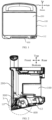
- FIG. 1 is a front view of a defibrillation device provided in an embodiment of this disclosure.
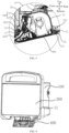
- FIG. 2 is a cross-sectional view of the defibrillation device shown in FIG. 1.
- FIG. 3 is a partially enlarged view of X in FIG. 2.
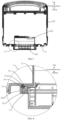
- FIG. 4 is a structural diagram of an opening apparatus for a door body of the defibrillation device shown in FIG. 1.
- FIG. 5 is a cross-sectional view of the defibrillation device shown in FIG. 4.
- FIG. 6 is a partially enlarged view of Y in FIG. 5.
- FIG. 7 is a structural diagram of a fitting structure between a recording instrument and a second partial housing of the defibrillation device shown in FIG. 1.
- FIG. 8 is a partially enlarged view of Z in FIG. 7.
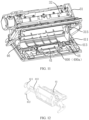
- FIG. 9 is an exploded view of a recording instrument and a door body of the defibrillation device shown in FIG. 1.
- FIG. 10 is a cross-sectional view of a recording instrument and a door body shown in FIG. 4.
- FIG. 11 is a first assembly diagram of a recording instrument and a door body of the defibrillation device shown in FIG. 1.
- FIG. 12 is a structural diagram of a handle shown in FIG. 11.
- FIG. 13 is a partial cross-sectional view of a handle and a door body shown in FIG. 10.
- FIG. 14 is a second assembly diagram of a recording instrument and a door body of the defibrillation device shown in FIG. 1.
- FIG. 15 is a 3D diagram of the defibrillation device shown in FIG. 1.
- FIG. 16 is a block diagram of the defibrillation device shown in FIG. 15.
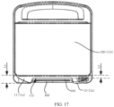
- FIG. 17 is another front view of the defibrillation device shown in FIG. 1.
-
Reference numbers shown in the drawings have following meanings.
- 100. Host housing; 11. First partial housing; 11a. First outer wall; 111. Fourth convex structure; 112. Sound output opening; 113. First opening; 114. First area; 12. Second partial housing; 12a. Second outer wall; 121. Inward convex part; 1211. First inside surface; 1212. Second inside surface; 122. First convex structure; 1221. First convex rib; 1222. Second convex rib; 123. First fastening structure; 13. Third partial housing; 14. Fourth partial housing; 141. Holding structure; 15. Fifth partial housing;
- 200. Display component; 21. Display structure layer; 22. Touch control layer;
- 300. Recording instrument; 31. Housing of recording instrument; 311. Second concave structure; 3111. First groove; 3112. Second groove; 312. First through-hole; 313. First position-limiting rib; 314. Second position-limiting rib; 315. First snap-fit; 32. Printing component; 33. First fastener; 34. First guide component; 341. Third groove; 35. Second guide component; 351. First insertion part; 352. Second insertion part; 353. Connection part; 3531. Third concave structure; 354. First paper output surface; 36. Paper roller;
- 400. Door body; 400a. Door body of recording instrument; 41. Handle; 411. Second snap-fit; 412. Abutting part; 413. Rotating shaft; 42. Second through-hole; 43. Second fastener; 44. Clamping part; 45. Second paper output surface; 451. Paper tearing structure; 452. Paper output opening; 46. Fixing structure for printing paper; 461. Circular lug boss;
- 500. Defibrillation module;
- 600. Parameter interface;
- 700. Treatment interface;
- H1. First direction; H2. Second direction; H3. Third direction; H4. Fourth direction.
DESCRIPTION OF THE PREFERRED EMBODIMENTS
-
The followings provide a clear and complete description of technical solutions in the embodiments of this disclosure combined with the accompanying drawings. Obviously, the described embodiments are only some of the embodiments of this disclosure, not all of them. Based on the embodiments in this disclosure, all other embodiments obtained by those skilled in the art without creative labor fall within the protection scope of this disclosure.
-
The embodiment of this disclosure provides a defibrillation device for timely defibrillation of patient with arrhythmia, such as atrial flutter, atrial fibrillation, supraventricular or ventricular tachycardia. Defibrillation device can be used in public places or in medical rooms, and the embodiments of this disclosure make no limitation for this.
-
Please refer to FIGS. 1 to 3. FIG. 1 is a front view of a defibrillation device provided in an embodiment of this disclosure. FIG. 2 is a cross-sectional view of the defibrillation device shown in FIG. 1. FIG. 3 is a partially enlarged view of X in FIG. 2. The defibrillation device includes a host housing 100, a display component 200, a recording instrument 300, and a door body 400.
-
The host housing 100 serves as an outer housing for the defibrillation device. The host housing 100 includes a first partial housing 11 at a first side and a second partial housing 12 at a second side. That is to say, assuming that the first partial housing 11 is located at a front surface of the host housing 100, or in other words, the first partial housing 11 serves as a front wall of the host housing 100, then the second partial housing 12 can be located at a bottom surface, a left surface, a right surface, a rear surface, or a top surface of the host housing 100, or in other words, the second partial housing 12 servers as a bottom wall, a left wall, a right wall, a rear wall, or a top wall of the host housing 100. The embodiments of this disclosure make no limitation for this. Of course, depending on the shape and placement state of the host housing 100, the first partial housing 11 may also be located at a tilted-up side or a tilted-down side of the host housing 100. Embodiments of this disclosure do not limit this. In the following description, embodiments of this disclosure is explained by taking the first partial housing 11 located at the front surface of the host housing 100, or in other words, the first side being the front side of the host housing 100 as an example.
-
The display component 200 is assembled at the first partial housing 11. That is to say, it can be understood that the display component 200 is assembled at the front surface or the front wall of the host housing 100.
-
The recording instrument 300 includes a housing 31 and a printing component 32. The housing 31 of the recording instrument is configured to accommodate printing paper. The housing 31 of the recording instrument is at least partially assembled at the host housing 100. The recording instrument 300 is configured such that the printing paper inside the housing 31 of the recording instrument is capable of being outputted to the first side of the host housing 100, or in other words, such that the printing paper inside the housing 31 of the recording instrument is capable of being outputted from the front surface of the host housing 100. The printing component 32 is assembled at the housing 31 of the recording instrument and is located at the host housing 100 for printing the printing paper, which is accommodated inside the housing 31 of the recording instrument. Therefore, the recording instrument 300 is capable of printing the printing paper and then outputting the printed paper from the front surface of the host housing 100, making it convenient for a user to obtain the printed paper outputted by the recording instrument 300.
-
The recording instrument 300 is further configured such that an orthographic projection of the recording instrument 300 on the first side at least partially overlaps with an orthographic projection of the display component 200 on the first side. Or in other words, an orthographic projection of the recording instrument 300 on a surface, where the display component 200 is located, at least partially overlaps with the display component 200. Therefore, it can also be understood that the recording instrument 300 is at least partially located behind the display component 200. So that, compared to setting the recording instrument 300 and the display component 200 side by side at the front surface of the host housing 100, as the recording instrument 300 is at least partially hidden behind the display component 200, the display component 200, which is located at the front surface of the host housing 100 in embodiments of this disclosure, can be made larger to increase the screen-to-body ratio of the front surface of the host housing 100.
-
The door body 400 is at least partially located at the second side of the host housing 100. The door body 400 is movably connected with the housing 31 of the recording instrument and/or the host housing 100, so as to enable the door body 400 to open or close an opening at the housing 31 of the recording instrument, thereby enabling the printing paper to be placed into or taken out from the housing 31 of the recording instrument from a side of the second partial housing 12 of the host housing 100. That is to say, the door body 400 of the defibrillation device for replacing the printing paper is at least partially located in an area outside the front surface of the host housing 100, allowing the recording instrument 300 to replace the printing paper from the area outside the front surface of the host housing 100. Therefore, compared to reserving a larger area in the front surface of the host housing 100 for paper replacement, the display component 200, which is located at the front surface of the host housing 100 in the embodiment of this disclosure, can be made larger to increase the screen-to-body ratio at the front surface of the host housing 100.
-
Thus it can be seen, on the basis of outputting the printing paper from the front surface of the host housing 100 for the use to obtain the printing paper, the embodiment of this disclosure reserves more space at the front surface of the defibrillation device to assemble a larger display component 200 by hiding at least a portion of the recording instrument 300 behind the display component 200 and setting the recording instrument 300 to replace the printing paper from surfaces other than the front surface of the host housing 100, thereby increasing the screen-to-body ratio at the front surface of the defibrillation device. Finally, due to the assembly of the larger display component 200 at the front surface of the defibrillation device, the display component 200 displays more content, allowing user to obtain more interrelated information at once, thereby improving the defibrillation efficiency and convenience when using the defibrillation device.
-
As an example, that the orthogonal projection of the recording instrument 300 on the first side at least partially overlaps with the orthogonal projection of the display component 200 on the first side, includes, an orthogonal projection of the housing 31 of the recording instrument on the first side at least partially overlaps with the orthogonal projection of the display component 200 on the first side. In other words, the orthogonal projection of the housing 31 of the recording instrument on a plane, where the display component 200 is located, at least partially overlaps with the display component 200.
-
That is to say, in a vertical direction, the housing 31 of the recording instrument can be completely located at a rear side of the display component 200, or optionally a portion of the housing 31 of the recording instrument, such as four fifths, a half, or one third of the housing 31 of the recording instrument, is located at the rear side of the display component 200. This is not limited by the embodiments of this disclosure.
-
Optionally, that the orthogonal projection of the recording instrument 300 on the first side at least partially overlaps with the orthogonal projection of the display component 200 on the first side, includes, an orthogonal projection of the printing component 32 on the first side at least partially overlaps with the orthogonal projection of the display component 200 on the first side. In other words, the orthogonal projection of the printing component 32 on a plane, where the display component 200 is located, at least partially overlaps with the display component 200.
-
That is to say, in a vertical direction, the printing component 32 can be completely located at a rear side of the display component 200, or optionally a portion of the printing component 32, such as four fifths, a half, or one third of the printing component 32, is located at the rear side of the display component 200. This is not limited by the embodiments of this disclosure.
-
It can also be understood that, it is possible that just the orthogonal projection of the housing 31 of the recording instrument on the first side at least partially overlaps with the orthogonal projection of the display component 200 on the first side; or just the orthogonal projection of the printing component 32 on the first side at least partially overlaps with the orthogonal projection of the display component 200 on the first side; or both the orthogonal projection of the housing 31 of the recording instrument and the orthogonal projection of the printing component 32 on the first side at least partially overlap with the orthogonal projection of the display component 200 on the first side. This is not limited by the embodiments of this disclosure.
-
It can also be understood that, taking the display component 200 as a touch control panel, the touch control panel can include a display structure layer 21 and a touch control layer 22 located outside the display structure layer 21. The display structure layer 21 is used for imaging and displaying information. For example, the display structure layer 21 can be a display structure layer of liquid crystal, including a backlight module, an optical film layer, an array substrate, and a color filter film layer, or the display structure layer 21 can be an OLEDM (Organic Light Emitting Diode) display layer, etc. The embodiments of this disclosure make no limitation for this. The touch control layer 22 is configured to receive touch operations. For example, the touch control layer 22 can be a transparent cover plate provided with a capacitive touch control structure, a resistive touch control structure, or an infrared touch control structure.
-
It can be understood that an orthographic projection of the display structure layer 21 on the first side is usually smaller than an orthographic projection of the touch control layer 22 on the first side. In additional, the orthographic projection of display structure layer 21 on the first side is located within the orthographic projection of the touch control layer 22 on the first side. In other words, the touch control layer 22 typically has a larger area than the display structure layer 21 and covers the entire display structure layer 21.
-
At this point, it is possible that the orthographic projection of the recording instrument 300 on the first side just at least partially overlaps with the orthographic projection of the touch control layer 22 on the first side, or the orthographic projection of the recording instrument 300 on the first side further at least partially overlaps with the orthographic projection of the display structure layer 21 on the first side, which is not limited by embodiments of this disclosure.
-
In some embodiments, in order to make the overall structure of the defibrillation device more compact, the recording instrument 300 can be partially arranged side by side with the display structure layer 21 at an inside surface of the touch control layer 22, and partially located at a side of the display structure layer 21 facing away from the touch control layer 22. It can also be understood that the recording instrument 300 is partially located at a lower side of the display structure layer 21 and partially at a rear side of the display structure layer 21, which can fully utilize an area behind the touch control layer 22 where no display structure layer 21 is arranged, thus ultimately making the defibrillation device as a whole smaller.
-
As an example, the printing component 32 of the recording instrument 300 can be partially arranged side by side with the display structure layer 21 at the inside surface of the touch control layer 22, and partially located at a side of the display structure layer 21 facing away from the touch control layer 22. Furthermore, compared to that the entire printing component 32 is located at one side of the display structure layer 21 facing away from the touch control layer 22, the printing component 32 can be closer to the outer surface of the first partial housing 11. Such that a paper output path for the printing paper to be outputted from the printing component 32 to the outside of the host housing 100 is shorter, thereby reducing the blockage probability of the printing paper inside the host housing 100.
-
Alternatively, the printing component 32 can also be arranged as a whole at one side of the display structure layer 21 facing away from the touch control layer 22, and embodiments of this disclosure do not limit this.
-
The above are some rough examples of the overall position of the recording instrument 300 in the embodiment of this disclosure. Below, a distance explanation is given for the technical solution of the embodiment of this disclosure in combination with the host housing 100 and some connecting and fitting structures of the recording instrument 300.
-
In some embodiments, in order to improve the protection of internal components of the host housing 100, a part which connects with the host housing 100 and the housing 31 of the recording instrument may be provided with a corresponding seal structure.
-
For example, the housing 31 of the recording instrument can only penetrate through the second partial housing 12 to be assembled and fixed at the host housing 100, such that the seal structure can be arranged between the second partial housing 12 and the housing 31 of the recording instrument. Optionally, the housing 31 of the recording instrument can also be connected and fitted with the second partial housing 12 and the first partial housing 11, respectively. Therefore, a connection part between the second partial housing 12 and the housing 31 of the recording instrument can be provided with a seal structure, and a connection part between the first partial housing 11 and the housing 31 of the recording instrument can also be provided with the seal structure. Embodiments of this disclosure do not limit this.
-
As an example, the second partial housing 12 includes an inward convex part 121 extending from its outer surface toward an interior of the host housing 100. At least a portion of the inward convex part 121 is provided with a first convex structure 122 or a first concave structure (not shown in the figure), and the housing 31 of the recording instrument is provided with a second concave structure 311 or a second convex structure that fits with the first convex structure 122 or the first concave structure to seal between the housing 31 of the recording instrument and the second partial housing 12.
-
On the one hand, the fitting between the first convex structure 122 or the first concave structure and the second concave structure 311 or the second convex structure can refer to a tight snap-in connection to achieve a seal, or a throttling gap formed therebetween so as to form a labyrinth seal structure. The embodiments of this disclosure are not limited to this.
-
On the other hand, it can be that the inward convex part 121 is provided with a first convex structure 122, the housing 31 of the recording instrument is provided with a second concave structure 311, and the first convex structure 122 is inserted into the second concave structure 311. It can also be that the inward convex part 121 is provided with a first concave structure, the housing 31 of the recording instrument is provided with a second convex structure, and the second convex structure is inserted (such as snap-in connection or clearance fitting) into the first concave structure. It can also be that the inward convex part 121 is provided with a first convex structure 122, and the housing 31 of the recording instrument is provided with a second convex structure. Along a direction in which the outer surface of the second partial housing 12 faces inwardly, the first convex structure 122 and the second convex structure are misaligned with each other, forming an interface between adjacent surfaces of the inward convex part 121 and the housing 31 of the recording instrument, which interface extends inwardly from the outer surface of the second partial housing 12 in a zigzagged way, thus ultimately achieving a seal and waterproof effect.
-
Of course, in some other embodiments, the inward convex part 121 can also be provided with both a first convex structure 122 and a first concave structure. Along a direction in which the outer surface of the second partial housing 12 faces inwardly, the first convex structure 122 and the first concave structure are misaligned with each other. For example, the first convex structure 122 is located below the first concave structure, or the first concave structure is located below the first convex structure 122. Correspondingly, the housing 31 of the recording instrument is also provided with a second convex structure and a second concave structure 311. Furthermore, the first convex structure 122 is snap-fitted to the second concave structure 311 to form a first seal in a vertical direction, and the second convex structure is snap-fitted the first concave structure to form a second seal in the vertical direction. Alternatively, the first convex structure 122 is inserted into the second concave structure 311, and the second convex structure is inserted into the first concave structure, so that the first convex structure 122, the first concave structure, the second convex structure, and the second concave structure 311 cooperate to form a labyrinth seal.
-
It can be understood that any concave-convex fitting structure, which seals between the housing 31 of the recording instrument and the second partial housing 12, is within the protection scope of embodiments of this disclosure, embodiments of this disclosure do not limit this.
-
Please continue to refer to FIGS. 4 to 6. FIG. 4 is a structural diagram of an opening apparatus for a door body of the defibrillation device shown in FIG. 1. FIG. 5 is a cross-sectional view of the defibrillation device shown in FIG. 4. FIG. 6 is a partially enlarged view of Y in FIG. 5. Below, take the second partial housing 12 provided with a first convex structure 122 and the housing 31 of the recording instrument provided with a second concave structure 311 as examples, so as to illustrate the technical solution of embodiments of this disclosure.
-
The inward convex part 121 includes a first inside surface 1211 which faces the first partial housing 11. The first convex structure 122 includes a first convex rib 1221 which protrudes from the first inside surface 1211. The second concave structure 311 includes a first groove 3111 with an opening which faces the first inside surface 1211. The first convex rib 1221 is snapped into the first groove 3111.
-
Thus, considering that the first partial housing 11 is located at the front surface of the host housing 100 as described above, which can also be understood as that the first inside surface 1211 is located behind the first partial housing 11 and faces the first partial housing 11, at this time, the housing 31 of the recording instrument is sandwiched between the first inside surface 1211 and the first partial housing 11, and the first convex rib 1221 extends from left to right. Furthermore, the seal for the rear surface the housing 31 of the recording instrument can be achieved through the fitting of the first convex rib 1221 and the first groove 3111.
-
In addition, since the first convex rib 1221 is snapped into the first groove 3111, it can also form a first connective fixation between the second partial housing 12 and the housing 31 of the recording instrument.
-
In order to improve the stability of the connective fixation between the housing 31 of the recording instrument and the second partial housing 12, the housing 31 of the recording instrument is provided with a first through-hole 312 that connects the interior of the housing 31 of the recording instrument and the interior of the host housing 100. A first fastener 33 penetrates through the first through-hole 312. The inward convex part 121 is provided with a first fastening structure 123, and the first fastener 33 is detachably connected with the first fastening structure 123.
-
Specifically, the first fastener 33 can be a screw, pin, or the likes. For example, the first fastener 33 is a screw, and the first fastening structure 123 can have threaded holes to allow the screw to be threaded into the threaded hole after penetrating into the first through-hole 312.
-
It can also be understood that on the one hand, compared to that the first fastener 33 is exposed outside of the second partial housing 12, since the first fastener 33 is hidden inside the housing 31 of the recording instrument and the host housing 100, the embodiment of this disclosure can make the outer surface of the second partial housing 12 more tidy and beautiful. On the other hand, compared to that through holes are arranged at the second partial housing 12 to assemble screws, the embodiment of this disclosure can avoid a decrease in seal performance caused by opening holes at the second partial housing 12.
-
Please continue to refer to FIGS. 7 and 8. FIG. 7 is a structural diagram of a fitting structure between a recording instrument and a second partial housing of the defibrillation device shown in FIG. 1. FIG. 8 is a partially enlarged view of Z in FIG. 7. The inward convex part 121 also includes two second inside surfaces 1212, and the housing 31 of the recording instrument is located between the two second inside surfaces 1212, which extend from different ends of the first inside surface 1211 toward the first partial housing 11. Correspondingly, the first convex structure 122 also includes two second convex ribs 1222, each second inside surface 1212 is provided with one second convex rib 1222. The second concave structure 311 also includes two second grooves 3112, and one second convex rib 1222 is snapped into one second groove 3112.
-
At this point, combining that the first inside surface 1211 mentioned above is located behind the housing 31 of the recording instrument, it can be understood that one second inside surfaces 1212 is located at the left side of the housing 31 of the recording instrument and extends from rear to front, and the other second inside surface 1212 is located at the right side of the housing 31 of the recording instrument and extends from rear to front. Correspondingly, the second convex rib 1222 of each second inside surface 1212 extends from rear to front, so that the left and right sides of the housing 31 of the recording instrument are respectively fitted with one second inside surface 1212 to achieve a seal.
-
Below, we continue to provide examples of some optional structures of the housing 31 of the recording instrument to further explain and illustrate the second groove 3112 and the second convex rib 1222.
-
In some embodiments, two pairs of position-limiting ribs protrude from the outer surface of the housing 31 of the recording instrument, each pair of position-limiting ribs include a first position-limiting rib 313 and a second position-limiting rib 314. Both pairs of position-limiting ribs extend from the first inside surface 1211 toward the first partial housing 11. Such that, it can be understood that one pair of position-limiting ribs protrude from rear to front at the left side of the housing 31 of the recording instrument, while the other one pair of position-limiting ribs protrude from rare to front at the right side of the housing 31 of the recording instrument. At this point, the first position-limiting rib 313 and the second position-limiting rib 314 in each pair of position-limiting ribs, as well as the outer surface of the housing 31 of the recording instrument, can form the second groove 3112 mentioned above for fitting with the corresponding second convex rib 1222.
-
Specifically, the first position-limiting rib 313 in the first pair of position-limiting ribs (such as the pair of position-limiting ribs located at the left side of the housing 31 of the recording instrument) abuts against a side of a first second convex rib 1222 (such as the second convex rib located at the left side of the housing 31 of the recording instrument), which side is adjacent to the outside of the second partial housing 12. Optionally, it can also be understood as that the first position-limiting rib 313 abuts against a lower side of the second convex rib 1222. The second position-limiting rib 314 in the first pair of position-limiting ribs is arranged at one side of the first second convex rib 1222, which side back-faces the first position-limiting rib 313. Optionally, it can also be understood that the second position-limiting rib 314 is located above the corresponding second convex rib 1222. In this way, the second position-limiting rib 314 in the first pair of position-limiting ribs, the first second convex rib 1222, as well as the outer surface of the housing 31 of the recording instrument, together form a first insertion groove.
-
Correspondingly, the defibrillation device also includes a first insertion part 351, which is detachably inserted into a first insertion groove to clamp the second convex rib 1222 between the corresponding first insertion part 351 and the first position-limiting rib 313. Furthermore, the first second convex rib 1222 is tightly clamped between the first pair of position-limiting ribs through the first insertion part 351.
-
It can also be understood that since the first position-limiting rib 313 and the second position-limiting rib 314 extend from rear to front, one end of the first insertion groove which is adjacent to the first partial housing 11, or in other words, a front end of the first insertion groove, is an open structure, so that the first insertion part 351 can be inserted into the first insertion groove from front to rear. In this way, during the assembly process of the housing 31 of the recording instrument, the first groove 3111 at the rear side of the housing 31 of the recording instrument can be tightly snapped with the first convex rib 1221 firstly; then the second convex rib 1222 at the left side of the housing 31 of the recording instrument can be inserted between the first position-limiting rib 313 and the second position-limiting rib 314 at the left side; and finally, the first insertion part 351 is inserted from front to rear into the first insertion groove, so that the second convex rib 1222 at the left side is tightly snapped into the first insertion groove.
-
Meanwhile, due to the addition of the first insertion part 351, the second convex rib 1222 at the left side can be more tightly snapped into the second groove 3112 at the left side of the housing 31 of the recording instrument. On the one hand, this can improve the seal effect of the seal structure at the left side of the housing 31 of the recording instrument, and on the other hand, can also improve the stability of the connection between the housing 31 of the recording instrument and the second partial housing 12.
-
In addition, the first position-limiting rib 313 in the second pair (such as the pair of position-limiting ribs located at the right side of the housing 31 of the recording instrument) abuts against a side of a second second convex rib 1222 (such as the second convex rib located at the right side of the housing 31 of the recording instrument), which side is adjacent to the outside of the second partial housing 12. Optionally, it can also be understood as that the first position-limiting rib 313 abuts against a lower side of the second convex rib 1222. The second position-limiting rib 314 in the second pair of position-limiting ribs is arranged at one side of the second second convex rib 1222, which side back-faces the first position-limiting rib 313. Or in other words, the second position-limiting rib 314 is located above the corresponding second convex rib 1222. In this way, the second position-limiting rib 314 in the second pair of position-limiting ribs, the second second convex rib 1222, as well as the outer surface of the housing 31 of the recording instrument, together form a second insertion groove.
-
Correspondingly, please continue to combine FIG. 9, which is an exploded view of a recording instrument and a door body of the defibrillation device shown in FIG. 1. The defibrillation device also includes a second insertion part 352, which can be detachably inserted into the second insertion groove to clamp the second convex rib 1222 between the corresponding insertion part and the first position-limiting rib 313. Furthermore, the second convex rib 1222 is clamped between the second pair of position-limiting ribs through the second insertion part 352.
-
It can also be understood that since the first position-limiting rib 313 and the second position-limiting rib 314 extend from rear to front, one end of the second insertion groove which is adjacent to the first partial housing 11, or in other words, a front end of the second insertion groove, is an open structure, so that the second insertion part 352 can be inserted into the second insertion groove from front to rear. In this way, during the assembly process of the housing 31 of the recording instrument, the first groove 3111 at the rear side of the housing 31 of the recording instrument can be tightly snapped with the first convex rib 1221 of the first inside surface 1211 firstly; then the second convex rib 1222 at the right side of the housing 31 of the recording instrument can be inserted between the first position-limiting rib 313 and the second position-limiting rib 314 at the right side; and finally, the second insertion part 352 is inserted from front to rear into the second insertion groove, so that the second convex rib 1222 at the right side is tightly snapped into the second insertion groove.
-
Meanwhile, due to the addition of the second insertion part 352, the second convex rib 1222 at the right side can be more tightly snapped into the second groove 3112 at the right side of the housing 31 of the recording instrument. On the one hand, this can improve the seal effect of the seal structure at the right side of the housing 31 of the recording instrument, and on the other hand, can also improve the stability of the connection between the housing 31 of the recording instrument and the second partial housing 12.
-
In some embodiments, the defibrillation device further includes a connection part 353, which is partially located between the housing 31 of the recording instrument and the first partial housing 11. Moreover, the connection part 353 is located between two second inside surfaces 1212. Ends of the connection part 353, which are respectively adjacent to each second inside surface 1212, are respectively connected with one insertion part to enable both ends of the connection part 353 to clamp the housing 31 of the recording instrument through the insertion part.
-
Specifically, the connection part 353 is connected with the first insertion part 351 at one end, which end is adjacent to a first second inside surface 1212 (such as the second inside surface 1212 at the left side), and the connection part 353 is connected with the second insertion part 352 at one end, which end is adjacent to the other second inside surface 1212 (such as the second inside surface 1212 at the right side). Furthermore, during the assembly of the housing 31 of the recording instrument, the connection part 353 can be pulled and pushed, so as to simultaneously insert the first insertion part 351 into the first insertion groove and insert the second insertion part 352 into the second insertion groove, ultimately improving the disassembling efficiency of the housing 31 of the recording instrument.
-
In some embodiments, the connection part 353 and at least one insertion part can be integrally formed, thereby reducing the overall number of components of the defibrillation device, thus further reducing the assembly difficulty of the defibrillation device and improving the assembly efficiency of the defibrillation device. Of course, the connection strength between the connection part 353 and the insertion part can also be improved. For example, the first insertion part 351, the second insertion part 352, and the connection part 353 are integrally formed through injection molding, or only the connection part 353 and the first insertion part 351 are integrally formed. Of course, in some other embodiments, the connection part 353 and the both insertion parts can be individually manufactured and assembled, and embodiments of this disclosure do not limit this.
-
Below, we continue to provide examples of the seal structure between the front side of the housing 31 of the recording instrument and the first partial housing 11 in the embodiment of this disclosure, in conjunction with the structure of the connection part 353.
-
Please refer to FIG. 3. A side of the connection part 353, which side back-faces the first inside surface 1211 is provided with a third convex structure or a third concave structure 3531. Optionally, in other words, a front side of the connection part 353 is provided with a third convex structure or a third concave structure 3531. The inner surface of the first partial housing 11 is provided with a fourth concave structure or a fourth convex structure 111 that fits with the third convex structure or the third concave structure 3531 to seal between the connection part 353 and the first partial housing 11. Moreover, the front side of the housing 31 of the recording instrument abuts against so as to be fixed to the inside surface of the first partial housing 11 through the connection part 353. In this way, the seal between the connection part 353 and the first partial housing 11 can also seal between the first partial housing 11 and the front side of the housing 31 of the recording instrument.
-
Specifically, it can be that the connection part 353 is provided with a third convex structure, the inner surface of the first partial housing 11 is provided with a fourth concave structure. Optionally, it can be that the connection part 353 is provided with a third concave structure 3531, and the inner surface of the first partial housing 11 is provided with a fourth convex structure 111. This embodiment of this disclosure does not limit this.
-
Of course, in some other embodiments, the connection part 353 can also be provided with both the third convex structure and the third concave structure 3531, and the first partial housing 11 can be provided with both the fourth concave structure and the fourth convex structure 111. Furthermore, the third convex structure and the fourth concave structure can be fitted to form a first seal between the connection part 353 and the first partial housing 11, while the third concave structure 3531 and the fourth convex structure 111 can be fitted to form a second seal between the connection part 353 and the first partial housing 11. The embodiments of this disclosure make no limitation for this.
-
In summary, the rear side of the housing 31 of the recording instrument is sealed by the fitting of the first groove 3111 and the first convex rib 1221. The left and right sides of the housing 31 of the recording instrument can be sealed by the fitting of the second groove 3112 and the second convex rib 1222. The front side of the housing 31 of the recording instrument can be sealed by the fitting of the connection part 353 and the first partial housing 11.
-
Optionally, one or more sides of the front side, rear side, left side, and right side of the housing 31 of the recording instrument can be sealed through corresponding concave and convex structures, while the remaining portions can be sealed through other structures, such as sealing rubber strips, sealing sponges, etc. Embodiments of this disclosure do not limit this.
-
The above are some examples of the seal structures at the front, left, right, and rear sides of the housing 31 of the recording instrument in the embodiment of this disclosure. The following continues to provide examples of a structure of the door body 400 in the embodiment of this disclosure.
-
Please continue to refer to FIG. 10, which is a cross-sectional view of a recording instrument and a door body shown in FIG. 4. The movable connection methods of the door body 400 can be diverse, for example the door body 400 can be rotatably connected or movable connected, and embodiments of this disclosure do not limit this.
-
For example, at least one of the housing 31 of the recording instrument and the host housing 100 is rotatably connected with the door body 400 to enable the door body 400 to rotate in a first direction H1, so as to open the housing 31 of the recording instrument, and to enable the door body 400 to rotate in a second direction H2, so as to close the housing 31 of the recording instrument. The first direction H1 is opposite to the second direction H2, so it can also be understood that the door body 400 can rotate forward to open the door and backward to close the door.
-
Wherein, the door body 400 can only be rotatably connected with the housing 31 of the recording instrument, so it can be considered as a part of the recording instrument 300 for synchronous disassembly and assembly with the recording instrument 300. Alternatively, the door body 400 can also be rotatably connected only to the host housing 100, or the door body 400 can be rotatably connected with both the host housing 100 and the recording instrument 300 at the same time. Embodiments of this disclosure do not limit this.
-
In some embodiments, in order to facilitate the opening and closing of the door body 400, the door body 400 is provided with a handle 41. A fixed end of the handle 41 is rotatably connected with the door body 400, so that handle 41 can rotate in a third direction H3 until a free end of the handle 41 is away from the door body 400, and the handle 41 can rotate in a fourth direction H4 until the free end of the handle 41 is adjacent to the door body 400, wherein the third direction H3 is opposite to the fourth direction H4. Furthermore, the handle 41 is capable of rotating in the fourth direction H4 to be attached to the door body 400 for easy storage, and the handle 41 is further capable of rotating in the third direction H3 to stand up from the door body 400 for facilitating grip of user.
-
Wherein, the third direction H3 can be same as the first direction H1, and the fourth direction H4 can be same as the second direction H2.
-
It can be understood that taking the second partial housing 12 as a bottom wall of the host housing 100 as an example, the fixed end of the door body 400 is located at its rear side and is rotatably connected with the housing 31 of the recording instrument in a closed state. At this point, if the door body 400a of the recording instrument rotates in the first direction H1 to open the door, the free end of the door body 400, or in other words, the front end of the door body 400, flips backwards. If the handle 41 can rotate in the third direction H3 until the free end of the handle 41 is far away from the door body 400, the free end of the handle 41 flips backwards to stand up from the door body 400, so as to be held. Therefore, the user can flip backward the handle 41 to grasp it and then continue to flip the handle 41 backward to open the door body 400. Therefore, compared to pulling the handle 41 forward, leftward, or rightward firstly, and then backwards to open the door, the door body 400 of embodiments of this disclosure is more convenient to open.
-
Alternatively, the third direction H3 can also be opposite to the first direction H1, and the fourth direction H4 can also be opposite to the second direction H2. The embodiment of this disclosure does not limit this.
-
Please continue to refer to FIG. 11, which is a first assembly diagram of a recording instrument and a door body of the defibrillation device shown in FIG. 1. The inner wall of the housing 31 of the recording instrument is provided with a first snap-fit 315, and the handle 41 is provided with a second snap-fit 411. When the door body 400 closes the housing 31 of the recording instrument, the handle 41 is capable of rotating in the fourth direction H4 until the first snap-fit 315 is snap-fitted with the second snap-fit 411, so as to lock the door body 400 and the housing 31 of the recording instrument. Moreover, the handle 41 is capable of rotating in the third direction H3 to separate the first snap-fit 315 and the second snap-fit 411, so as to unlock the door body 400 and the housing 31 of the recording instrument.
-
That is to say, when the door body 400 closes the housing 31 of the recording instrument, the handle 41 rotates in the fourth direction H4 to be attached to the door body 400, and the first snap-fit 315 is also snap-fitted with the second snap-fit 411 to lock the door body 400. When the handle 41 rotates in the third direction H3 to stand up from the door body 400, the first snap-fit 315 is also separated from the second snap-fit 411 to unlock the door body 400. Such that, when the user opens the door, the user can pull back the handle 41 to complete three actions in one go, which actions include pulling out the handle 41, unlocking the second snap-fit 411, and opening the door body 400. In this way, the opening of the door body 400 is more convenient.
-
Meanwhile, since the first snap-fit 315 is assembled inside the housing 31 of the recording instrument, compared to exposing the first snap-fit 315, the embodiment of this disclosure can also make the external surface of the defibrillation device more beautiful, tidy, and not easily damaged.
-
Please continue to refer to FIG. 12, which is a structural diagram of a handle shown in FIG. 11. The handle 41 can also be provided with an abutting part 412. The abutting part 412 is located at a side of the fixed end of the handle 41, which side back-faces the free end of the handle 41, and a distance from the fixed end of the handle 41 to the abutting part is smaller than a distance from the fixed end of the handle 41 to the free end of the handle 41. Furthermore, the handle 41 can be regarded as a lever as a whole, with the fixed end of the handle 41 being a fulcrum of the handle 41, and a first force arm formed from the abutting part to the fulcrum is smaller than a second arm formed from the free end of the handle 41 to the fulcrum. at least at one moment during handle 41 rotating in the third direction H3, the abutting part 412 abuts against the housing 31 of the recording instrument. That is to say, during the process of rotating the handle 41 to stand up relative to the door body 400, the first force arm can form a resistance arm, and the second force arm can form a power arm. Since the power arm is larger than the resistance arm, user can open the door through the handle 41 more effortlessly.
-
Specifically, the abutting part 412 can be rotated to abut against the first snap-fit 315. Furthermore, there is no need to assemble additional structures inside the housing 31 of the recording instrument to fit the abutting part 412, such that the internal structure of the housing 31 of the recording instrument can be simpler, reducing the manufacturing difficulty and support cost of the housing 31 of the recording instrument.
-
Please continue to refer to FIG. 13, which is a partial cross-sectional view of a handle and a door body shown in FIG. 10. In order to ensure a smoother output process of printing paper to the outside of the host housing 100, the inner surface of the door body 400 can be provided with a first guide component 34. The first guide component 34 is configured to guide the printing paper inside the housing 31 of the recording instrument to the outside of the host housing 100.
-
Continuing to combine the above embodiment in which the door body 400 is provided with the handle 41, the fixed end of the handle 41 can be provided with a rotating shaft 413, so that the handle 41 can rotate the door body 400 through the rotating shaft 413. Specifically, the first guide component 34 is provided with a third groove 341 at a side which faces the door body 400, wherein the third groove 341 and the inner surface of the door body 400 forms a rotating hole. The rotating shaft 413 is rotatably assembled inside the rotating hole. Therefore, the first guide component 34 can also be reused for assembling and fixing the handle 41 to reduce the overall number of components in the defibrillation device, thereby making the defibrillation device lighter and thinner, and making disassembly and assembly easier.
-
Wherein, the second snap-fit 411 and the abutting part 412 mentioned above can be formed at the rotating shaft 413.
-
Wherein, in order to drive the handle 41 to rotate in the fourth direction H4, a torsion spring can also be provided at the handle 41. One torsion arm of the torsion spring abuts against the inner surface of the door body 400, and the other torsion arm of the torsion spring abuts against the rotating shaft 413, so as to drive the rotating shaft 413 and the handle 41 connected with the rotating shaft 413 to rotate in the fourth direction H4, thus ultimately enabling the handle 41 to be attached to the door body 400 and enabling the first snap-fit 315 to be snap-fitted with the second snap-fit 411.
-
The handle 41 and the rotating shaft 413 can be integrally formed, or detachable connected through screw connection, sleeve connection, fitting connection, etc. The embodiment of this disclosure does not limit this.
-
In some embodiments, as shown in FIG. 10, the door body 400 may be provided with a second through-hole 42, a second fastener 43 penetrates through and is arranged inside the second through-hole 42. The second fastener 43 is detachably connected with the first guide component 34, and then the first guide component 34 is fixed and assembled through the second fastener 43.
-
Specifically, the second fastener 43 can be a screw, pin, or the like. Taking the second fastener 43 as an example, which is a screw, the first guide component 34 can have a threaded hole, so that the screw can be threaded into the threaded hole after penetrating the second through hole 42.
-
In order to enhance the appearance of the defibrillation device, the handle 41 can be rotated in the fourth direction H4 to cover the second through-hole 42. Furthermore, when the door body 400 closes the housing 31 of the recording instrument, the handle 41 can rotate in the fourth direction H4 to be attached to the door body 400, so as to cover the second through hole 42 and the second fastener 43 penetrating the second through hole 42.
-
In some embodiments, as shown in FIGS. 11 or 13, the door body 400 may also be provided with a clamping part 44, and the rotating shaft 413 can be rotatably clamped by the clamping part 44. Furthermore, the assembly and fixation of the rotating shaft 413 can be achieved through the clamping part 44.
-
It can be understood that the rotating shaft 413 can be assembled through the clamping part 44, and the rotating shaft 413 can also be assembled through the first guiding component 34. Embodiments of this disclosure do not limit this.
-
Optionally, the rotating shaft 413 can also be assembled simultaneously through the clamping part 44 and the first guide component 34 to ensure the assembly strength of the rotating shaft 413 through a dual fixation structure. Such that, the second snap-fit 411, which is arranged at the rotating shaft 413, can be prevented from being unable to lock the door body 400 due to the damage to the connection structure of the rotating shaft 413.
-
For example, the handle 41 can be arranged in a middle position of the door body 400, so that the corresponding second fastener 43 is also located inside the middle position of the door body 400 to fix the first guide component 34. At this time, at least one clamping part 44 is arranged at both left and right ends of the inner surface of the door body 400.
-
Of course, in some embodiments, the clamping part 44 can also be clamped at any position along an axial direction of the rotating shaft 413, and embodiments of this disclosure do not limit this. It can also be understood that during the specific assembly process, the rotating shaft 413 of the handle 41 can be clamped by the clamping part 44 to achieve preliminary assembly and fixation, and then the first guide component 34 can be assembled at the inner surface of door body 400 to further tighten the handle 41. From this, it can be seen that the embodiment of this disclosure enables the handle 41 to have the advantages of convenient and reliable assembly by double fixing the rotating shaft 413 with the clamping part 44 and the first guide component 34.
-
The above are some examples of the opening method of the door body 400 in the embodiment of this disclosure. The following continues to provide further explanation and illustration of a structure related to the printing paper in the recording instrument 300 in conjunction with the first guide component 34.
-
The inner surface of the door body 400 is provided with a first guide component 34, and the housing 31 of the recording instrument is provided with a second guide component 35 that fits with the first guide component 34. When the door body 400 is rotated to close the housing 31 of the recording instrument, the first guide component 34 and the second guide component 35 together form a paper output channel, which channel is configured to guide the printing paper inside the housing 31 of the recording instrument to be outputted to the outside of the host housing 100.
-
On the one hand, since the first guide component 34 can rotate with the door body 400, during the process of replacing the printing paper, some of the printing paper is directly pulled out a roll of the printing paper and placed at the first guide component 34. After the door body 400 is rotated to close the housing 31 of the recording instrument, the printing paper is directly located inside the paper output channel. In this way, during the process of replacing the printing paper, there is no need to manually pull the printing paper through different guide components or zigzagged paper output channels, making the replacement of the printing paper more convenient.
-
On the other hand, since the printing component 32 is at least partially located at the rear side of the display component 200 in the embodiment of this disclosure, compared to that the printing component 32 and the display component 200 are arranged side by side at the surface side of the first partial housing 11, the printing component 32 is naturally located in a deeper position of the host housing 100, which results in that the printing paper needs to take a longer path to be outputted to the front side of the host housing 100 after being printed by the printed component 32. Therefore, the possibility of jam for the printing paper inside the host housing 100 is even greater. Therefore, the embodiment of this disclosure can reduce the possibility of jam for the printing paper inside the host housing 100 by setting an output channel to guide the printing paper, thereby improving the reliability of the defibrillation device.
-
It can also be understood that the first insertion part 351, the second insertion part 352, and the connection part 353 mentioned above can all be portions of the second guide component 35, and the housing 31 of the recording instrument can be sealed by reusing the second guide component 35. Of course, the second guiding component 35 can also be an independent component fixed to the above-mentioned connection part 353, and embodiments of this disclosure do not limit this.
-
In some embodiments, please continue to refer to FIG. 14, which is a second assembly diagram of a recording instrument and a door body of the defibrillation device shown in FIG. 1. The second guide component 35 is provided with a first paper output surface 354 at one end, which end is adjacent to the first partial housing 11, and the door body 400 includes a second paper output surface 45 that is fitted with the first paper output surface 354. When the door body 400 is rotated to close the housing 31 of the recording instrument, the first paper output surface 354 and the second paper output surface 45 form a paper output opening 425, so as to output the printing paper in the paper output channel from the paper output opening 452 to the outside of the host housing 100. Furthermore, during the process of replacing the printing paper, some of the printing paper is directly pulled out from a roll of the printing paper, and placed at the first guide component 34 and the free end of the door body 400. After the door body 400 is rotated to close the housing 31 of the recording instrument, the printing paper is directly located inside the paper output channel. In this way, during the process of replacing the printing paper, there is no need to manually pull the printing paper through different guide components or zigzagged paper output channels, which make the replacement of printing paper more convenient.
-
Wherein, in order to facilitate the user to tear off the printing paper, at least one of the first paper output surface 354 and the second paper output surface 45 is provided with a paper tearing structure 451. That is to say, it can be that only the first paper output surface 354 can be provided with a paper tearing structure 451. It can also be that only the second paper output surface 45 is provided with a paper tearing structure 451. It can also be that both the first paper output surface 354 and the second paper output surface 45 are provided with a paper tearing structure 451, allowing user to tear paper from more directions.
-
In some embodiments, at least one end of the second paper output surface 45 is provided with a concave-convex structure along a width direction of outputted printing paper to form the paper tearing structure 451, and the middle portion of the second paper output surface 45 along the width direction of the outputted printing paper is a plane. Accordingly, the friction between the middle portion of the second paper output surface 45 and the printing paper is smaller to reduce the probability of jam for the printing paper at the paper output opening 452. At the same time, the paper tearing structures 451 at both ends enable edges of the printing paper to be more easily torn out, so as to facilitate tearing off the printing paper.
-
Alternatively, it is possible that the end of the paper output channel, which is adjacent to the first partial housing 11, is the paper output opening 452. Therefore, the printing paper can be directly outputted to one side of the first partial housing 11 of the host housing 100, or in other words, directly outputted to the front side of the host housing 100 through the paper output channel.
-
Wherein, in order to facilitate the user to tear off the printing paper, the second guide component 35 and/or the first guide component 34 are provided with the paper tearing structure 451 at the paper output opening 452. That is to say, it can be that only the second guide component 35 is provided with the paper tearing structure 451 at the paper output opening 452. It can also be that only the first guide component 34 is provided with the paper tearing structure 451 at the paper output opening 452. It can also be that the first guide component 34 and the second guide component 35 are both provided with the paper tearing structure 451 at the paper output opening 452, allowing user to tear paper from more directions.
-
As an example, the first guide component 34 is provided with a third paper output surface at the paper output opening 452. At least one end of the third paper output surface is provided with a concave-convex structure along the width direction of the outputted printing paper to form the tearing structure 451, and the middle portion of the third paper output surface along the width direction of the outputted printing paper is a plane. Accordingly, the friction between the middle portion of the paper output surface and the printing paper is smaller to reduce the probability of jam for the printing paper at the paper output opening 452. At the same time, the paper tearing structures 451 at both ends enable edges of the printing paper to be more easily torn out, so as to facilitate tearing off the printing paper.
-
Please continue to refer to FIG. 15, which is a 3D diagram of the defibrillation device shown in FIG. 1. In order to enable a larger display component 200 to be assembled to the first partial housing 11, the first partial housing 11 further includes a sound output opening 112, which is arranged side by side with the paper output opening 452 at the same side of the display component 200. For example, the paper output opening 452 and the sound output opening can be arranged side by side at the lower side of the first partial housing 11. Compared to arranging the paper output opening 452 at the lower side of the first partial housing 11 and arranging the sound output opening 112 at the left side of the first partial housing 11, a distance between the left side of the first partial housing 11 and the display component 200 in embodiments of this disclosure can be made smaller, which enables the width of the display component 200 to be larger in the left-right direction, so as to increase the screen-to-body ratio of the display component 200. Of course, in some other embodiments, the sound output opening 112 and the paper output opening 452 can also be respectively arranged at different sides of the first partial housing 11, and embodiments of this disclosure do not limit this.
-
In order to make the printing paper move more smoothly in the paper output channel, the first guide component 34 includes at least one smooth surface, which is configured to form an inner surface of the paper output channel to support the printing paper. Furthermore, by reducing the friction between the printing paper and the first guide component 34 through the smooth surface, the probability of jam for the printing paper in the output channel is reduced.
-
It can be understood that there are one or more smooth surfaces, and the embodiments of this disclosure make no limitation for this. Specifically, a moving path of the printing paper can be determined based on the placement position of the printing paper in the housing 31 of the recording instrument, the printing position of the printing component 32, and the position of the paper output opening 452, etc., and then the printing paper can be supported and guided through one or more smooth surfaces along the movement path of the printing paper.
-
In some embodiments, in order to facilitate the printing of the printing paper by the printing component 32, the recording instrument 300 may also include a paper roller 36, which is configured to fit with the printing component 32 to press the printing paper tightly onto the printing position of the printing component 32.
-
For example, as shown in FIG. 14, the paper roller 36 is rotatably assembled at the first guide component 34 to support the printing paper passing through the first guide component 34, and the printing component 32 is configured to press and print the printing paper supported by the paper roller 36.
-
Alternatively, the paper roller 36 can also be rotatably assembled at the housing 31 of the recording instrument or the second guide component 35, the printing component 32 is assembled at the first guide component 34, and the paper roller 36 is configured to press the printing paper passing through the first guide component 34 onto the printing component 32 for printing by the printing component 32.
-
It can be understood that since one of the printing component 32 and the paper roller 36 is assembled at the first guide component 34, while the first guide component 34 is assembled at the door body 400 and can be opened by following the rotation of the door body 400, such that during the process of replacing the printing paper, some printing paper is directly pulled out from the roll of printing paper and placed at the first guide component 34. In this way, after the door body 400 is rotated to close the housing 31 of the recording instrument, the printing paper is directly located inside the paper output channel and clamped between the printing component 32 and the paper roller 36. Such that, during the process of replacing the printing paper, there is no need to manually pull the printing paper through different guide components or zigzagged paper output channels, making the replacement of the printing paper more convenient.
-
Wherein, the printing component 32 can be a thermal printing device, an ink printing device, etc., which is not limited by the embodiments of this disclosure.
-
In some embodiments, in order to achieve the automatic paper output function of the recording instrument 300, the paper roller 36 may be provided with a first transmission structure, the printing component 32 may be provided with a driving component, which is connected with a second transmission structure. The second transmission structure and the first transmission structure can be separated and connected with each other, so that when the door body 400 opens the housing 31 of the recording instrument, the first transmission structure and the second transmission structure can be separated, and when the door body 400 closes the housing 31 of the recording instrument, the first transmission structure and the second transmission structure can be docked to form transmission connection.
-
For example, the driving components can be electric machines, motors, etc. The first transmission structure can be a first gear arranged at an axial end of the paper roller 36, and the second transmission structure can be a second gear connected with the driving component. When the door body 400 closes the housing 31 of the recording instrument, the first gear and the second gear mesh to achieve transmission connection. Of course, the first transmission structure and the second transmission structure can also be mutually fitted gears and racks, and the embodiments of this disclosure make no limitation for this.
-
The fixation methods of the printing paper accommodated inside the housing 31 of the recording instrument can be diverse, for example the printing paper can be fixed at the door body 400 or fixed at the housing 31 of the recording instrument. Embodiments of this disclosure do not limit this.
-
For example, the printing paper is fixed at the door body 400. The inner surface of the door body 400 is provided with a fixing structure 46 for the printing paper, which is used to assemble the printing paper. It can be understood that since the fixing structure 46 for the printing paper can follow the movement of the door body 400 to the outside of the housing 31 of the recording instrument when opening the door body 400, replacing the printing paper at the door body 400 is more convenient and simpler compared to replacing the printing paper inside the housing 31 of the recording instrument.
-
For example, as shown in FIG. 9, the fixing structure 46 for the printing paper may include two spaced elastic clamping arms to clamp the roll made of printing paper.
-
Specifically, the roll of printing paper can include a hollow paper drum and printing paper wound outside the drum. In this way, a circular lug boss 461 can be arranged at a side of each elastic clamping arm, which side faces the other elastic clamping arm, and the circular lug boss 461 of the two elastic clamping arms can be pivoted to fix the paper drum of the roll of printing paper.
-
The above are some examples of the structure of the recording instrument 300 in the embodiment of this disclosure. Below, we continue to provide examples of the overall structure of the defibrillation device in the embodiment of this disclosure.
-
Please refer to both FIG. 15 and FIG. 16. FIG. 16 is a block diagram of the defibrillation device shown in FIG. 15. The host housing 100 also includes a third partial housing 13, a fourth partial housing 14, and a fifth partial housing 15. The first partial housing 11, the second partial housing 12, the third partial housing 13, the fourth partial housing 14, and the fifth partial housing 15 face different sides, respectively.
-
For example, in combination with that the first partial housing 11 located at the front side of the host housing 100, the second partial housing 12, the third partial housing 13, the fourth partial housing 14, and the fifth partial housing 15 can be sequentially located at the bottom side, left side, top side, and right side of the host housing 100. In other words, the second partial housing 12, the third partial housing 13, the fourth partial housing 14, and the fifth partial housing 15 can be sequentially the bottom wall, left wall, top wall and right wall of the host housing 100. Of course, it can also be understood that the orientations of each partial housing at the host casing 100 are interchangeable, and the embodiments of this disclosure make no limitation for this.
-
The defibrillation device can also include a defibrillation module 500, a parameter interface 600, and a treatment interface 700. The defibrillation module 500 is assembled inside the host housing 100 to process state information of human body and provide a defibrillation current and/or voltage. The parameter interface 600 is arranged inside the third partial housing 13, and is configured to connect detection components, such as some sensors or detection electrodes. The parameter interface 600 is also electrically connected with the defibrillation module 500 to enable the defibrillation module 500 to obtain state information of human body through the detection components, thereby providing more suitable defibrillation current and/or voltage. The treatment interface 700 is arranged inside the fifth partial housing 15, and is configured to connect a defibrillation electrode. The treatment interface 700 is also electrically connected with the defibrillation module 500 to enable the defibrillation module 500 to apply the defibrillation current and/or voltage to the human body through the defibrillation electrode.
-
It can be understood that the defibrillation electrode can be a pre-assembled component of the defibrillation device, or be an external or consumable component which is plugged into the treatment interface 700, etc. The embodiment of this disclosure does not limit this.
-
The defibrillation electrode can be either an electrode sheet or an electrode plate. Correspondingly, taking the fourth partial housing 14 located at the top surface of the host housing 100 as an example, a storage area can be arranged at the fourth partial housing 14 for placing defibrillation electrodes, such as electrode sheets or electrode plates.
-
In order to facilitate the use to move the defibrillation device, the defibrillation device can also include a holding structure 141, which is arranged inside the fourth partial housing 14. Specifically, the holding structure 141 can be a handle or the likes to facilitate the user to lift the defibrillation device.
-
The display component 200 can also be electrically connected with the defibrillation module 500, so as to display the working state of the defibrillation device, state information of patient body, usage indication, and so on. Of course, the display component 200 can also be a touch screen with touch function for user to interact with the defibrillation device, which is not limited in embodiments of this disclosure.
-
The recording instrument 300 can also be electrically connected with the defibrillation module 500 for printing work log of the defibrillation device, state information of patient body, and so on.
-
Please continue to refer to FIG. 17, which is another front view of the defibrillation device shown in FIG. 1. The embodiment of this disclosure also provides a defibrillation device, which includes a host housing 100, a display component 200, and a recording instrument 300.
-
The host housing 100 serves as a housing of the entire defibrillation device, and includes a first partial housing 11 at a first side and a second partial housing 12 at a second side. That is to say, assuming that the first partial housing 11 is located at a front side of the host housing 100, or in other words that the first partial housing 11 is a front wall of the host housing 100, the second partial housing 12 can be located at a bottom surface, a left surface, a right surface, a rear surface, or a top surface of the host housing 100, or in other words, the second partial housing 12 can be a bottom wall, a left wall, a right wall, a rear wall, or a top wall of the host housing 100. The embodiments of this disclosure make no limitation for this. In the following, the embodiment of this disclosure is explained by taking the first partial housing 11 located at the front surface of the host housing 100 as an example.
-
The display component 200 is assembled at the first partial housing 11, which can be understood as being assembled at the front surface or front wall of the host housing 100.
-
The recording instrument 300 is at least partially assembled at the host housing 100, and is configured to hold and print the printing paper.
-
Wherein, the defibrillation device is configured such that: the printing paper which is to be printed is capable of being placed into and taken out from the recording instrument via the second side, which means that the defibrillation device is configured such that, the printing paper is replaced from the area outside the front surface of the host housing 100. Therefore, compared to reserving a larger area at the front surface of the host housing 100 for paper replacement, the display component 200 at the front surface of the host housing 100 in embodiments of this disclosure can be made larger to increase the screen-to-body ratio at the front surface of the host housing 100.
-
The defibrillation device is also configured such that, the printed paper is outputted from the first side, which means that the recording instrument 300 can output the printed paper from the front surface of the host housing 100 for facilitating the user to obtain.
-
Meanwhile, as there is no need to reserve a large area at the front surface of the host housing 100 for paper replacement, a distance L1 between a frame of display component 200, which frame is adjacent to the second partial housing 12, and the second partial housing 12 is less than 35 millimeters.
-
For example, the second partial housing 12 can be located at the bottom surface of the host housing 100, which means that the distance L1 between a lower frame of the display component 200 and the second partial housing 12 can be 35 millimeters, 24 millimeters, 12.3 millimeters, etc. The printing paper can be outputted from an area, which is less than 35 millimeters below the display component 200, so that the screen-to-body ratio of the display component 200 at the front surface of the host housing 100 can be larger.
-
In some embodiments, the structures of the host housing 100, display component 200, and recording instrument 300 can respectively refer to in the aforementioned host housing 100, display component 200, and recording instrument 300. The embodiments of this disclosure give no unnecessary details .
-
In some embodiments, the defibrillation device may further include one or more of the door body 400, the first insertion part 351, the second insertion part 352, the connection part 353, the first guide component 34, the second guide component 35, the defibrillation module 500, the parameter interface 600, the holding structure 141, and the treatment interface 700. Wherein the specific structures of the door body 400, the first insertion part 351, the second insertion part 352, the connection part 353, the first guide component 34, the second guide component 35, the defibrillation module 500, the parameter interface 600, the holding structure 141, and the treatment interface 700, may refer to the above mentioned door body 400, first insertion part 351, second insertion part 352, connection part 353, first guide component 34, second guide component 35, defibrillation module 500, parameter interface 600, holding structure 141, and treatment interface 700, respectively. The embodiments of this disclosure give no unnecessary details herein.
-
As shown in FIG. 17, embodiments of this disclosure also provide a defibrillation device, which includes a host housing 100, a display component 200, and a recording instrument 300.
-
The host housing 100 can serve as a housing of the entire defibrillation device, and includes a first partial housing 11 at a first side and a second partial housing 12 at a second side. That is to say, assuming that the first partial housing 11 is located at the front side of the host housing 100, or in other words that the first partial housing 11 is a front wall of the host housing 100, the second partial housing 12 can be located at a bottom surface, a left surface, a right surface, a rear surface, or a top surface of the host housing 100, or that the second partial housing 12 can be the a bottom wall, a left wall, a right wall, a rear wall, or a top wall of the host housing 100. The embodiments of this disclosure make no limitation for this. In the following, the embodiment of this disclosure is explained by taking the first partial housing 11 located at the front surface of the host housing 100 as an example.
-
The display component 200 can be assembled at the first partial housing 11, which can be understood as being assembled at the front surface of the host housing 100.
-
The recording instrument 300 is at least partially assembled at the host housing 100, and is configured to hold and print the printing paper.
-
Wherein, the defibrillation device is configured such that: the printing paper which is to be printed is capable of being placed into and taken out from the recording instrument via the second side, which means that the defibrillation device is configured such that, the printing paper is replaced from the area outside the front surface of the host housing 100. Therefore, compared to reserving a larger area at the front surface of the host housing 100 for paper replacement, the display component 200 at the front surface of the host housing 100 in embodiments of this disclosure can be made larger to increase the screen-to-body ratio at the front surface of the host housing 100.
-
The first partial housing 11 includes a first side edge, which located in a fifth direction of the display component 200, wherein the first side edge is provided with a first opening 11 to output printed paper. This means that the recording instrument 300 can output the printed paper from the front surface of the host housing 100 for facilitating user to obtain. An orthographic projection of the first opening 113 in the fifth direction at least partially overlaps with an orthographic projection of the display component 200 in the fifth direction, or the first opening 113 is at least partially located at the lower side of the display component 200. A minimum distance L2 between the display component 200 and the first opening 113 is less than 25 millimeters, for example, the minimum distance L2 can be 25 millimeters, 20 millimeters, 13.7 millimeters, 8.1 millimeters, and so on. Furthermore, by transferring a paper replacement area for the recording instrument 300, which is reserved by the host housing 100, to other surfaces of the host housing 100, and compressing the distance between the display component 200 and the first opening 113, the display component 200 has a larger screen proportion at the front surface of the host housing 100.
-
In some embodiments, the structures of the host housing 100, the display component 200, and the recording instrument 300 can respectively refer to the aforementioned host housing 100, display component 200, and recording instrument 300. The embodiments of this disclosure give no unnecessary details .
-
In some embodiments, the defibrillation device may further include one or more of the door body 400, the first insertion part 351, the second insertion part 352, the connection part 353, the first guide component 34, the second guide component 35, the defibrillation module 500, the parameter interface 600, the holding structure 141, the treatment interface 700. The specific structures of the door body 400, the first insertion part 351, the second insertion part 352, the connection part 353, the first guide component 34, the second guide component 35, the defibrillation module 500, the parameter interface 600, the holding structure 141, and the treatment interface 700 can refer to the above mentioned door body 400, first insertion part 351, second insertion part 352, connection part 353, first guidance component 34, second guidance component 35, defibrillation module 500, parameter interface 600, holding structure 141, and treatment interface 700, respectively. The embodiments of this disclosure give no unnecessary details herein.
-
As shown in FIG. 17, the embodiment of this disclosure further provides a defibrillation device, including a host housing 100, a display component 200, and a recording instrument 300.
-
The host housing 100 serves as a housing of the entire defibrillation device, and includes a first outer wall 11a at a first side and a second outer wall 12a at a second side. That is to say, assuming that the first outer wall 11a is located at a front surface or front side of the host housing 100, the second outer wall 12a can be located at a bottom surface, a left surface, a right surface, a rear surface, or a top surface of the host housing 100. The embodiment of this disclosure does not limit this, of course, depending on the shape and placement state of the host housing 100, the first outer wall 11a may also be located at a side of the host housing 100, which side is inclined upwardly or downwardly, etc. The embodiments of this disclosure make no limitation for this. In the following, the embodiments of this disclosure continue to explain the first partial housing 11 located at the front side of the host housing 100 as an example.
-
The display component 200 is assembled at the first outer wall 11a, which can be understood as being assembled at the front surface of the host housing 100.
-
The recording instrument 300 is at least partially assembled at the host housing 100, and configured to accommodate and print printing paper.
-
Wherein, the defibrillation device is configured such that the printing paper which is printed is capable of being outputted from the first side, which means that the defibrillation device is configured such that the printed paper is capable of being outputted from the front surface for the user to obtain the printed paper from the front surface. In addition, the defibrillation device is configured such that: the printing paper which is to be printed is capable of being placed into and taken out from the recording instrument 300 via the second side, such that there is no need to reserve a large area at the front surface of the host housing 100 for paper replacement. Based on this, the defibrillation device can also be configured with a display component 200 covering at least 50% of an outer surface of the first outer wall 11a, so that the display component 200 has a larger screen-to-body ratio at the front surface of the defibrillation device.
-
For example, the display component 200 covers 50%, 60%, and 71.4% of the outer surface of the first outer wall 11a, which is not limited by embodiments of this disclosure.
-
In some embodiments, the structures of the host housing 100, the display component 200, and the recording instrument 300 can respectively refer to the host housing 100, the display component 200, and the recording instrument 300 mentioned above. The first outer wall 11a can be the outer wall of the first partial housing 11 facing the front surface, and the second outer wall 12a can be the outer wall of the second partial housing 12 facing the bottom surface. The embodiments of this disclosure give no unnecessary details herein.
-
In some embodiments, the defibrillation device may further include one or more of the door body 400, the first insertion part 351, the second insertion part 352, the connection part 353, the first guide component 34, the second guide component 35, the defibrillation module 500, the parameter interface 600, the holding structure 141, and the treatment interface 700. The specific structures of the door body 400, the first insertion part 351, the second insertion part 352, the connection part 353, the first guide component 34, the second guide component 35, the defibrillation module 500, the parameter interface 600, the holding structure 141, and the treatment interface 700 can refer to the above mentioned door body 400, first insertion part 351, second insertion part 352, connection part 353, first guidance component 34, second guidance component 35, defibrillation module 500, parameter interface 600, holding structure 141, and treatment interface 700, respectively. The embodiments of this disclosure give no unnecessary details herein.
-
As shown in FIGS. 1 to 3, the embodiment of this disclosure also provides a defibrillation device, including a host housing 100, a display component 200, a recording instrument 300, and a door body 400.
-
The host housing 100 serves as a housing of the entire defibrillation device, and includes a first partial housing 11 at a first side and a second partial housing 12 at a second side which is adjacent to the first side. That is to say, assuming that the first partial housing 11 is located at a front surface, or in other words at a front side of the host housing 100, the second partial housing can be located at a bottom surface, a left surface, a right surface, or a top surface of the host housing 100. The embodiment of this disclosure does not limit this. But of course, depending on the shape and placement state of the host housing 100, The first partial housing 11 may also be located at a side of the host housing 100, which is inclined upwardly or downwardly. The embodiments of this disclosure make no limitation for this. In the following, the embodiments of this disclosure continue to use the first partial housing 11 located at the front side of the host housing 100 as an example for explanation.
-
The display component 200 can be assembled at the first partial housing 11, which can be understood as being assembled at the front surface of the host housing 100.
-
The recording instrument 300 includes a housing 31 and a printing component 32. The housing 31 of the recording instrument is configured to accommodate printing paper, and the housing 31 of the recording instrument is at least partially assembled at the host housing 100. The recording instrument 300 is configured such that the printing paper inside the housing 31 of the recording instrument is capable of being outputted to the first side of the host housing 100. In other words, the printing paper inside the housing 31 of the recording instrument can be outputted from the front surface of the host housing 100, so as to facilitate user to obtain the printing paper. The printing component 32 is assembled at the housing 31 of the recording instrument and is located inside the host housing 100 for printing the printing paper accommodated inside the housing 31 of the recording instrument. The printing component 32 is arranged along a direction toward the second partial housing 12, inclining toward or away from a plane in which the display component 20 is located. Alternatively, it can be understood that the printing component is inclined forwardly or backwardly from top to bottom. Compared to arranging the printing component 32 and the display component 200 side by side, a total height of the printing component 32 and the display component 200 in a vertical direction according to embodiments of this disclosure is lower, and thus the height of the first partial housing 11 in the vertical direction can be made shorter. Therefore, assuming that the size of the display component 200 and the printing component 32 is constant, conversely speaking, the screen-to-body ratio of the display component 200 at the front side of the first partial housing 11 can be larger.
-
The door body 400 is at least partially located at one side of the second partial housing 12 of the host housing 100. The door body 400 is movably connected with the housing 31 of the recording instrument and/or the host housing 100, so as to enable the door body 400 to open or close an opening at the housing 31 of the recording instrument, thereby enabling that the printing paper is capable of being placed into or taken out from the housing 31 of the recording instrument via one side of the second partial housing 12 of the host housing 100. In other words, the door body 400 used by the defibrillation device for replacing printing paper is at least partially located in an area which is outside the front surface of the host housing 100, which further enables that the printing paper is capable of being placed into or taken out from the recording instrument 300 via the area outside the front surface of the host housing 100. Therefore, compared to reserving a larger area at the front surface of the host housing 100 for paper replacement, the display component 200 at the front surface of the host housing 100 in embodiments of this disclosure can be made larger to increase the screen-to-body ratio at the front surface of the host housing 100.
-
From this, it can be seen that on the basis of outputting printing paper from the front surface of the host housing 100 for facilitating the user to obtain the printing paper, embodiments of this disclosure can increase the screen-to-body ratio at the front surface of the defibrillation device by inclining the printing component 32 and arranging the recording instrument 300 to replace the printing paper from surfaces other than the front surface of the host housing 100.
-
In some embodiments, the structures of the host housing 100, the display component 200, and the recording instrument 300 can respectively refer to the host housing 100, the display component 200, and the recording instrument 300 mentioned above. The first outer wall 11a can be the outer wall of the first partial housing 11 facing the front surface, and the second outer wall 12a can be the outer wall of the second partial housing 12 facing the bottom surface. The embodiments of this disclosure give no unnecessary details herein.
-
In some embodiments, the defibrillation device may further include one or more of the door body 400, the first insertion part 351, the second insertion part 352, the connection part 353, the first guide component 34, the second guide component 35, the defibrillation module 500, the parameter interface 600, the holding structure 141, and the treatment interface 700. The specific structures of the door body 400, first insertion part 351, the second insertion part 352, the connection part 353, the first guide component 34, the second guide component 35, the defibrillation module 500, the parameter interface 600, the holding structure 141, and the treatment interface 700 can refer to in the above mentioned door body 400, first insertion part 351, second insertion part 352, connection part 353, first guidance component 34, second guidance component 35, defibrillation module 500, parameter interface 600, holding structure 141, and treatment interface 700, respectively. The embodiments of this disclosure give no unnecessary details herein.
-
As shown in FIG. 17, the embodiment of this disclosure also provides a medical device, which can be a monitor, defibrillation device, etc. The embodiment of this disclosure does not limit this. The medical device can include a host housing 100 and a recording instrument 300.
-
The host housing 100 includes a first partial housing 11 at a first side, and a second partial housing 12 at a second side. The first partial housing 11 has a first area 114 for fixing a display component 200. That is to say, assuming that the first partial housing 11 is located at a front surface, or in other words at a front side of the host housing 100, the second part can be located at a bottom surface, a left surface, a right surface, a rear surface, or a top surface of the host housing 100. The embodiment of this disclosure does not limit this. But of course, depending on the shape and placement state of the host housing 100, the first partial housing 11 may also be located at a side of the host housing 100, which is inclined upwardly or downwardly. The embodiments of this disclosure make no limitation for this. In the following, the embodiments of this disclosure continue to explain and illustrate the first partial housing 11 located at the front surface of the host housing 100, which means that the front surface of the host housing 100 has a first area 114 for assembling and fixing the display component 200.
-
The recording instrument 300 is at least partially assembled inside the host housing 100, and is configured to accommodate and print printing paper.
-
Wherein, the medical device is configured such that: the printing paper which is printed is capable of being outputted from the first side. In other words, the medical device is configured such that: the printing paper which is printed is capable of being outputted from the front surface for facilitating user to obtain.
-
In additional, the medical device is also configured such that the printing paper which is to be printed is capable of being placed into and taken out from the recording instrument 300 via the second side of the host housing 100, thereby enabling the recording instrument 300 to be configured such that the printing paper is capable of being replaced from an area outside the front surface of the host housing 100. Therefore, compared to reserving a larger area at the front surface of the host housing 100 for paper replacement, the first area 114 at the front surface of the host housing 100 in embodiments of this disclosure can be made larger to assemble a larger display component 200.
-
At the same time, an orthographic projection of the recording instrument 300 on the first side at least partially overlaps with an orthographic projection of the first area 114 on the first side. Alternatively, it can be understood that the recording instrument 300 is at least partially located at a rear side of the first area 114. Such that, compared to arranging the recording instrument 300 and the first area 114 side by side at the front surface of the host housing 100, the first area 114 at the front surface of the host housing 100 in embodiments of this disclosure can be made larger.
-
From this, it can be seen that on the basis of outputting the printing paper from the front surface of the host housing 100 to facilitate user to obtain, the embodiment of this disclosure can reserve more space at the front surface of the medical device to assemble a larger display component 200 by hiding at least a portion of the recording instrument 300 behind the first area 114 and arranging the recording instrument 300 to replace the printing paper from surfaces other than the front surface of the host housing 100, thereby increasing the screen-to-body ratio at the front surface of the defibrillation device.
-
In some embodiments, the structures of the host housing 100, the display component 200, and the recording instrument 300 can respectively refer to the aforementioned host housing 100, display component 200, and recording instrument 300. The embodiments of this disclosure give no unnecessary details .
-
In some embodiments, the defibrillation device may further include one or more of the door body 400, the first insertion part 351, the second insertion part 352, the connection part 353, the first guide component 34, the second guide component 35, the defibrillation module 500, the parameter interface 600, the holding structure 141, and the treatment interface 700. Wherein the specific structures of the door body 400, the first insertion part 351, the second insertion part 352, the connection part 353, the first guide component 34, the second guide component 35, the defibrillation module 500, the parameter interface 600, the holding structure 141, and the treatment interface 700 can refer to the above mentioned door body 400, first insertion part 351, second insertion part 352, connection part 353, first guidance component 34, second guidance component 35, defibrillation module 500, parameter interface 600, holding structure 141, and treatment interface 700, respectively. The embodiments of this disclosure give no unnecessary details herein.
-
The embodiment of this disclosure also provides a recording instrument 300, which is applied to a medical device. The medical device can be a defibrillation device, a monitor, a sample analyzer, etc. The embodiment of this disclosure does not limit this.
-
As shown in FIGS. 10 and 11, the recording instrument 300 includes a housing 31, a recording instrument door 400a, and a handle 41.
-
The housing 31 of the recording instrument is provided with an accommodating cavity and a second opening, wherein the accommodating cavity is configured to accommodate printing paper, the second opening is configured such that the printing paper is capable of being placed into or taken out from the accommodating cavity, and the housing 31 is further provided with a first snap-fit 315. The door body 400a of the recording instrument is rotatably connected with the housing 31 of the recording instrument, so as to enable the door body 400a of the recording instrument to rotate in a first direction H1 to open the second opening, and to enable the door body 400a of the recording instrument to rotate in a second direction H2 to close the second opening. The first direction H1 is opposite to the second direction H2. It can also be understood as that the door body 400 can rotate forward to open the door and backward to close the door. The handle 41 is provided with a second snap-fit 411, and a fixed end of the handle 41 is rotatably connected with the door body 400a of the recording instrument. Wherein, the handle 41 is capable of rotating in a fourth direction, so as to enable a free end of the handle 41 to be adjacent to the door body 400a of recording instrument, and so as to enable the second snap-fit 411 and the first snap-fit 315 to be snap-fitted for locking the door body 400a of the recording instrument and the housing 31 of the recording instrument. The handle 41 is further capable of rotating in a third direction, so as to enable the free end of the handle 41 to be away from the door body 400a of recording instrument, and so as to enable the second snap-fit 411 and the first snap-fit 315 to be separated for unlocking the door body 400a of the recording instrument and the housing 31 of the recording instrument. The third direction H3 is opposite to the fourth direction H4.
-
Therefore, it can also be understood that when the handle 41 is rotated to be attached to the door body 400a of the recording instrument, the door body 400a of the recording instrument is locked accordingly, and when the handle 41 is rotated to stand up from the door body 400a of the recording instrument, the door body 400a of the recording instrument is unlocked accordingly. In this way, by setting a simple structure of the second snap-fit 411 at the handle 41, user can more conveniently unlock or lock the door body 400.
-
Wherein, the third direction H3 can be the same as the first direction H1, and the fourth direction H4 can be the same as the second direction H2.
-
Then, taking an example of the door body 400a of the recording instrument located at the bottom surface of the medical device, the door body 400a of the recording instrument is roughly horizontal when it is closed, and a fixed end of the door body 400a of the recording instrument is located at its rear side and rotatably connected with the housing 31 of the recording instrument. At this point, if the door body 400a of the recording instrument is rotated in the first direction H1 to open the door, the free end of the door body 400, or in other words, the front end of the door body 400, flips backwards. The handle 41 can be rotated in the third direction H3 until the free end of the handle 41 is far away from the door body 400, can be that the free end of the handle 41 flips backwards to stand up from the door body 400. Therefore, the user can flip backward the handle 41 to grasp it and then continue to flip the handle 41 backward to open the door body 400. Therefore, compared to pulling the handle 41 forward, left, or right before opening the door, and then pulling the handle backward to open the door, the door body 400 of embodiments of this disclosure is more convenient to open.
-
Alternatively, the third direction H3 can also be opposite to the first direction H1, and the fourth direction H4 is opposite to the second direction H2. The embodiment of this disclosure does not limit this.
-
In some embodiments, as shown in FIG. 12, the handle 41 is further provided with an abutting part. The abutting part is located at a side of the fixed end of the handle 41, which side back-faces the free end, and a distance from the fixed end of the handle 41 to the abutting part is smaller than a distance from the fixed end of the handle 41 to the free end of the handle 41. Furthermore, the handle 41 can be regarded as a lever as a whole, with the fixed end of the handle 41 being a fulcrum of the handle 41, and a first force arm formed from the abutting part to the fulcrum is smaller than a second arm formed from the free end of the handle 41 to the fulcrum. When the first snap-fit 315 and the second snap-fit 411 switch between snap-fitted and separation states, the abutting part 412 abuts against the first snap-fit 315.
-
That is to say, during the process of rotating the handle 41 to stand up relative to the door body 400, the first force arm can form a resistance arm, and the second force arm can form a power arm. Since the power arm is larger than the resistance arm, user can open the door through the handle 41 more effortlessly.
-
In some embodiments, the housing 31 of the recording instrument and the door body 400a of the recording instrument can refer to the aforementioned housing 31 of the recording instrument and door body 400, respectively. The embodiments of this disclosure give no unnecessary details.
-
In some embodiments, the recording instrument 300 may also include one or more of the printing component 32, the first insertion part 351, the second insertion part 352, the connection part 353, the first guide component 34, and the second guide component 35. The specific structures of the printing component 32, the first insertion part 351, the second insertion part 352, the connection part 353, the first guide component 34, and the second guide component 35 can refer to the above-mentioned printing component 32, first insertion part 351, second guide component 35, second insertion part 352, connection part 353, first guide component 34, and second guide component 35, respectively. The embodiments of this disclosure give no unnecessary details .
-
In the above embodiments, the descriptions of each embodiment have their own emphasis. For the parts that are not detailed in one embodiment, please refer to the relevant descriptions of other embodiments.
-
The above provides a detailed description for the defibrillation device, medical device, and recording instrument 300 provided in the embodiments of this disclosure. Specific examples are applied in this disclosure to explain its principles and implementation methods. The explanations of the above embodiments are only used to help understand the methods and core ideas of this disclosure. Meanwhile, for technical personnel in this field, there may be changes in the specific embodiments and application scope based on the ideas of this disclosure. In summary, the content of this description should not be understood as a limitation on this disclosure.
EXAMPLES:
-
- 1. A defibrillation device, characterized in that, comprising:
- a host housing, which comprises a first partial housing at a first side and a second partial housing at a second side;
- a display component, which is assembled at the first partial housing;
- a recording instrument, which comprises a housing and a printing component, wherein the housing of the recording instrument is configured to accommodate printing paper, and the housing of the recording instrument is at least partially assembled at the host housing; wherein the recording instrument is configured such that the printing paper inside the housing of the recording instrument is capable of being outputted to the first side; wherein the printing component is assembled at the housing of the recording instrument and located at the host housing to print the printing paper, which is accommodated inside the housing of the recording instrument; wherein an orthographic projection of the recording instrument on the first side at least partially overlaps with an orthographic projection of the display component on the first side; and
- a door body, which is at least partially located at the second side and is movably connected with the housing of the recording instrument and/or the host housing; wherein the door body is capable of opening or closing an opening at the housing of the recording instrument, so as to enable the printing paper to be placed into and taken out from the housing of the recording instrument via the second side.
- 2. The defibrillation device according to example 1, characterized in that, an orthogonal projection of the housing of the recording instrument on the first side at least partially overlaps with the orthographic projection of the display component on the first side; and/or
an orthogonal projection of the printing component on the first side at least partially overlaps with the orthographic projection of the display component on the first side.
- 3. The defibrillation device according to example 1, characterized in that, the second partial housing comprises an inward convex part, which extends from an outer surface of the second partial housing toward an interior of the host housing; wherein at least a portion of the inward convex part is provided with a first convex structure or a first concave structure, and the housing of the recording instrument is provided with a second concave structure or a second convex structure that fits with the first convex structure or the first concave structure, so as to seal between the housing of the recording instrument and the second partial housing.
- 4. The defibrillation device according to example 3, characterized in that, the inward convex part comprises a first inside surface which faces the first partial housing, the first convex structure comprises a first convex rib which protrudes from the first inside surface, the second concave structure comprises a first groove with an opening which faces the first inside surface, wherein the first convex rib is snapped into the first groove.
- 5. The defibrillation device according to example 3, characterized in that, the housing of the recording instrument is provided with a first through-hole that connects with an interior of the housing of the recording instrument and the interior of the host housing, wherein a first fastener penetrates through and is arranged inside the first through-hole, and the inward convex part is provided with a first fastening structure, wherein the first fastener is detachably connected with the first fastening structure.
- 6. The defibrillation device according to example 4, characterized in that, the inward convex part further comprises two second inside surfaces, the housing of the recording instrument is located between the two second inside surfaces, which extend from different ends of the first inside surface toward the first partial housing;
the first convex structure further comprises two second convex ribs, wherein each second inside surface is provided with one second convex rib; the second concave structure further comprises two second grooves, wherein one second convex rib is snapped into one second groove.
- 7. The defibrillation device according to example 6, characterized in that, two pairs of position-limiting ribs protrude from an outer surface of the housing of the recording instrument, each pair of position-limiting ribs comprise a first position-limiting rib and a second position-limiting rib, both pairs of position-limiting ribs extend from the first inside surface toward the first partial housing;
- wherein the first position-limiting rib in one pair of position-limiting ribs abuts against a side of one second convex rib, which side is adjacent to an outside of the second partial housing; the second position-limiting rib in said one pair of position-limiting ribs is arranged at a side of said one second convex rib, which side back-faces the first position-limiting rib; such that the second position-limiting rib in said one pair of position-limiting ribs, said one second convex rib and the outer surface of the housing of the recording instrument, together form the first insertion groove;
- wherein the first position-limiting rib in the other pair of position-limiting ribs abuts against a side of the other second convex rib, which side is adjacent to the outside of the second partial housing; the second position-limiting rib in the other pair of position-limiting ribs is arranged at a side of the other second convex rib, which side back-faces the first position-limiting rib; such that the second position-limiting rib in the other pair of position-limiting ribs, the other second convex rib and the outer surface of the housing of the recording instrument, together form a second insertion groove;
- the defibrillation device further comprises a first insertion part and a second insertion part, which are detachably inserted into the first insertion groove and the second insertion groove, respectively, so as to clamp the second convex ribs between the insertion parts and the first position-limiting ribs.
- 8. The defibrillation device according to example 7, characterized in that, the defibrillation device further comprises a connection part, which is partially located between the housing of the recording instrument and the first partial housing, and the connection part is located between the two second inside surfaces; wherein both ends of the connection part, which are respectively adjacent to each second inside surface, are respectively connected with one of the insertion parts, so as to enable both ends of the connection part to clamp the housing of the recording instrument through the insertion parts.
- 9. The defibrillation device according to example 8, characterized in that, a side of the connection part, which side back-faces the first inside surface, is provided with a third convex structure or a third concave structure, an inner surface of the first partial housing is provided with a fourth concave structure or a fourth convex structure which fits with the third convex structure or the third concave structure.
- 10. The defibrillation device according to example 1, characterized in that, at least one of the housing of the recording instrument and the host housing is rotatably connected with the door body, so as to enable the door body to rotate in a first direction to open the housing of the recording instrument, and so as to enable the door body to rotate in a second direction to close the housing of the recording instrument; wherein the first direction is opposite to the second direction.
- 11. The defibrillation device according to example 10, characterized in that, the door body is provided with a handle, wherein a fixed end of the handle is rotatably connected with the door body, so as to enable the handle to rotate in a third direction until a free end of the handle is away from the door body, and so as to enable the handle to rotate in a fourth direction until the free end of the handle is adjacent to the door body; wherein the third direction is same as the first direction, and the fourth direction is same as the second direction.
- 12. The defibrillation device according to example 11, characterized in that, an inner wall of the housing of the recording instrument is provided with a first snap-fit, and the handle is provided with a second snap-fit; wherein the handle is capable of rotating in the fourth direction until the first snap-fit is snap-fitted with the second snap-fit, so as to lock the door body and the housing of the recording instrument, and the handle is further capable of rotating in the third direction to separate the first snap-fit and the second snap-fit, so as to unlock the door body and the housing of the recording instrument.
- 13. The defibrillation device according to example 12, characterized in that, the handle is further provided with an abutting part; wherein the abutting part is located at a side of the fixed end of the handle, which side back-faces the free end of the handle, wherein a distance from the fixed end of the handle to the abutting part is smaller than a distance from the fixed end of the handle to the free end of the handle;
wherein at least at one moment during the handle rotating in the third direction, the abutting part abuts against the housing of the recording instrument.
- 14. The defibrillation device according to example 12, characterized in that, an inner surface of the door body is provided with a first guide component, which is configured to guide the printing paper inside the housing of the recording instrument to an outside of the host housing;
- a side of the first guide component, which side faces the door body, is provided with a third groove, wherein the third groove and the inner surface of the door body together form a rotating hole;
- wherein the fixed end of the handle is provided with a rotating shaft, which is rotatably assembled inside the rotating hole.
- 15. The defibrillation device according to example 14, characterized in that, the door body is further provided with a second through-hole, wherein a second fastener penetrates through and is arranged inside the second through-hole; the second fastener is detachably connected with the first guide component, the handle is capable of rotating in the fourth direction to cover the second through-hole.
- 16. The defibrillation device according to example 15, characterized in that, the door body is further provided with a clamping part, and the rotating shaft is rotatably clamped by the clamping part.
- 17. The defibrillation device according to example 10, characterized in that, an inner surface of the door body is provided with a first guide component, the housing of the recording instrument is provided with a second guide component that fits with the first guide component; wherein, when the door body is rotated to close the housing of the recording instrument, the first guide component and the second guide component together form a paper output channel, wherein the paper output channel is configured to guide the printing paper inside the housing of the recording instrument to be outputted to an outside of the host housing.
- 18. The defibrillation device according to example 17, characterized in that, the first guide component comprises at least one smooth surface, which is configured to form an inner surface of the paper output channel to support the printing paper.
- 19. The defibrillation device according to example 17, characterized in that, a first paper output surface is arranged at one end of the second guide component, which end is adjacent to the first partial housing, and the door body comprises a second paper output surface that fits with the first paper output surface; wherein, when the door body is rotated to close the housing of the recording instrument, the first paper output surface and the second paper output surface together form a paper output opening, wherein the paper output opening is configured to guide the printing paper inside the paper output channel to be outputted to the outside of the host housing;
wherein at least one of the first paper output surface and the second paper output surface is provided with a paper tearing structure.
- 20. The defibrillation device according to example 19, characterized in that, at least one end of the second paper output surface is provided with a concave-convex structure along a width direction of the printing paper to form the paper tearing structure, wherein a middle portion of the second paper output surface along the width direction of the printing paper is a plane.
- 21. The defibrillation device according to example 19, characterized in that, the first partial housing further comprises a sound output opening, which is arranged side by side with the paper output opening at a same side of the display component.
- 22. The defibrillation device according to example 17, characterized in that, the recording instrument further comprises a paper roller, which is rotatably assembled at the first guide component to support the printing paper which passes through the first guide component, wherein the printing component is configured to press and print the printing paper which is supported by the paper roller; or
the recording instrument further comprises a paper roller, which is rotatably assembled at the housing of the recording instrument, the printing component is assembled at the first guide component; wherein the paper roller is configured to press the printing paper, which passes through the first guide component, onto the printing component for printing.
- 23. The defibrillation device according to example 10, characterized in that, an inner surface of the door body is provided with a fixing structure for the printing paper, which is configured to fix the printing paper.
- 24. The defibrillation device according to example 23, characterized in that, the fixing structure for the printing paper comprises two spaced elastic clamping arms, which are configured to clamp a roll of the printing paper.
- 25. The defibrillation device according to any one of examples 1-24, characterized in that, the host housing further comprises a third partial housing, a fourth partial housing and a fifth partial housing; wherein the first partial housing, the second partial housing, the third partial housing, the fourth partial housing and the fifth partial housing face different sides, respectively;
wherein the defibrillation device further comprises:
- a defibrillation module, which is arranged inside the host housing, and configured to process state information of a human body and provide a defibrillation current and/or voltage;
- a parameter interface, which is arranged at the third partial housing and connected with a detection component, wherein the parameter interface is electrically connected with the defibrillation module, so as to enable the defibrillation module to acquire the state information of the human body through the detection component;
- a holding structure, which is arranged at the fourth partial housing; and
- a treatment interface, which is arranged at the fifth partial housing and connected with a defibrillation electrode, wherein the treatment interface is electrically connected with the defibrillation module, so as to enable the defibrillation module to apply the defibrillation current and/or voltage to the human body through the defibrillation electrode.
- 26. A defibrillation device, characterized in that, comprising:
- a host housing, which comprises a first partial housing at a first side and a second partial housing at a second side;
- a display component, which is assembled at the first partial housing; and
- a recording instrument, which is at least partially assembled at the host housing and configured to accommodate and print printing paper;
- wherein, the defibrillation device is configured such that: the printing paper which is to be printed is capable of being placed into and taken out from the recording instrument via the second side, and the printing paper which is printed is capable of being outputted from the first side; wherein a distance between a frame of the display component and the second partial housing is less than 35 millimeters, wherein the frame of the display component is adjacent to the second partial housing.
- 27. A defibrillation device, characterized in that, comprising:
- a host housing, which comprises a first partial housing at a first side and a second partial housing at a second side;
- a display component, which is assembled at the first partial housing; and
- a recording instrument, which is at least partially assembled at the host housing and configured to accommodate and print printing paper;
- wherein, the defibrillation device is configured such that: the printing paper which is to be printed is capable of being placed into and taken out from the recording instrument via the second side, wherein the first partial housing comprises a first side edge which is located in a fifth direction of the display component, and the first side edge is provided with a first opening for outputting the printing paper which is printed, wherein an orthographic projection of the first opening along the fifth direction at least partially overlaps with an orthographic projection of the display component along the fifth direction, wherein a minimum distance between the display component and the first opening is less than 25 millimeters.
- 28. A defibrillation device, characterized in that, comprising:
- a host housing, which comprises a first outer wall at a first side and a second outer wall at a second side;
- a display component, which is assembled at the first outer wall; and
- a recording instrument, which is at least partially assembled at the host housing and configured to accommodate and print printing paper;
- wherein, the defibrillation device is configured such that: the printing paper which is printed is capable of being outputted from the first side, and the printing paper which is to be printed is capable of being placed into and taken out from the recording instrument via the second side; wherein the display component covers at least 50% of an outer surface of the first outer wall.
- 29. A defibrillation device, characterized in that, comprising:
- a host housing, which comprises a first partial housing at a first side and a second partial housing at a second side, wherein the second side is adjacent to the first side;
- a display component, which is assembled at the first partial housing;
- a recording instrument, which comprises a housing and a printing component, wherein the housing of the recording instrument is configured to accommodate printing paper, and the housing of the recording instrument is at least partially assembled at the host housing; wherein the recording instrument is configured such that the printing paper inside the housing of the recording instrument is capable of being outputted to the first side, and the printing component is assembled at the housing of the recording instrument and located inside the host housing for printing the printing paper, which is accommodated inside the housing of the recording instrument; wherein the printing component is arranged along a direction toward the second partial housing, inclining toward or away from a plane in which the display component is located; and
- a door body, which is at least partially located at the second side and is movably connected with the housing of the recording instrument and/or the host housing; wherein the door body is capable of opening or closing an opening at the housing of the recording instrument, so as to enable the printing paper to be placed into and taken out from the housing of the recording instrument via the second side.
- 30. A medical device, characterized in that, comprising:
- a host housing, which comprises a first partial housing at a first side and a second partial housing at a second side, wherein the first partial housing is provided with a first area for fixing a display component; and
- a recording instrument, which is at least partially assembled inside the host housing and configured to accommodate and print printing paper;
- wherein the medical device is configured such that: the printing paper which is printed is capable of being outputted from the first side, and the printing paper which is to be printed is capable of being placed into and taken out from the recording instrument via the second side; wherein an orthographic projection of the recording instrument on the first side at least partially overlaps with an orthographic projection of the first area on the first side.
- 31. A recording instrument, which is applied to a medical device, characterized in that, comprising:
- a housing, which is provided with an accommodating cavity and a second opening, wherein the accommodating cavity is configured to accommodate printing paper, the second opening is configured such that the printing paper is capable of being placed into and taken out from the accommodating cavity, and the housing is further provided with a first snap-fit;
- a door body, which is rotatably connected with the housing, so as to enable the door body to rotate in a first direction to open the second opening, and so as to enable the door body to rotate in a second direction to close the second opening, wherein the first direction is opposite to the second direction; and
- a handle, which is provided with a second snap-fit, wherein a fixed end of the handle is rotatably connected with the door body;
- wherein, the handle is capable of rotating in a fourth direction, so as to enable a free end of the handle to be adjacent to the door body, and so as to enable the second snap-fit to be snap-fitted with the first snap-fit for locking the door body and the housing;
- the handle is further capable of rotating in a third direction, so as to enable the free end of the handle to be away from the door body, and so as to enable a separation between the second snap-fit and the first snap-fit for unlocking the door body and the housing; wherein the third direction is opposite to the fourth direction.
- 32. The recording instrument according to example 31, characterized in that, the fourth direction is same as or opposite to the second direction.
- 33. The recording instrument according to example 32, characterized in that, the handle is further provided with an abutting part, wherein the abutting part is located at a side of the fixed end of the handle, which side back-faces the free end of the handle, wherein a distance from the fixed end of the handle to the abutting part is smaller than a distance from the fixed end of the handle to the free end of the handle;
wherein when the first snap-fit and the second snap-fit are switched between snap-fitted and separated states, the abutting part abuts against the first snap-fit.