EP4387925B1 - Process for the preparation of green ammonia synthesis gas - Google Patents
Process for the preparation of green ammonia synthesis gas Download PDFInfo
- Publication number
- EP4387925B1 EP4387925B1 EP22757215.3A EP22757215A EP4387925B1 EP 4387925 B1 EP4387925 B1 EP 4387925B1 EP 22757215 A EP22757215 A EP 22757215A EP 4387925 B1 EP4387925 B1 EP 4387925B1
- Authority
- EP
- European Patent Office
- Prior art keywords
- stream
- hydrogen
- nitrogen
- synthesis gas
- separate
- Prior art date
- Legal status (The legal status is an assumption and is not a legal conclusion. Google has not performed a legal analysis and makes no representation as to the accuracy of the status listed.)
- Active
Links
Images
Classifications
-
- B—PERFORMING OPERATIONS; TRANSPORTING
- B01—PHYSICAL OR CHEMICAL PROCESSES OR APPARATUS IN GENERAL
- B01D—SEPARATION
- B01D53/00—Separation of gases or vapours; Recovering vapours of volatile solvents from gases; Chemical or biological purification of waste gases, e.g. engine exhaust gases, smoke, fumes, flue gases, aerosols
- B01D53/02—Separation of gases or vapours; Recovering vapours of volatile solvents from gases; Chemical or biological purification of waste gases, e.g. engine exhaust gases, smoke, fumes, flue gases, aerosols by adsorption, e.g. preparative gas chromatography
- B01D53/04—Separation of gases or vapours; Recovering vapours of volatile solvents from gases; Chemical or biological purification of waste gases, e.g. engine exhaust gases, smoke, fumes, flue gases, aerosols by adsorption, e.g. preparative gas chromatography with stationary adsorbents
- B01D53/047—Pressure swing adsorption
-
- B—PERFORMING OPERATIONS; TRANSPORTING
- B01—PHYSICAL OR CHEMICAL PROCESSES OR APPARATUS IN GENERAL
- B01D—SEPARATION
- B01D53/00—Separation of gases or vapours; Recovering vapours of volatile solvents from gases; Chemical or biological purification of waste gases, e.g. engine exhaust gases, smoke, fumes, flue gases, aerosols
- B01D53/34—Chemical or biological purification of waste gases
- B01D53/74—General processes for purification of waste gases; Apparatus or devices specially adapted therefor
- B01D53/86—Catalytic processes
- B01D53/8671—Removing components of defined structure not provided for in B01D53/8603 - B01D53/8668
-
- C—CHEMISTRY; METALLURGY
- C01—INORGANIC CHEMISTRY
- C01B—NON-METALLIC ELEMENTS; COMPOUNDS THEREOF; METALLOIDS OR COMPOUNDS THEREOF NOT COVERED BY SUBCLASS C01C
- C01B21/00—Nitrogen; Compounds thereof
- C01B21/04—Purification or separation of nitrogen
- C01B21/0405—Purification or separation processes
- C01B21/0433—Physical processing only
- C01B21/045—Physical processing only by adsorption in solids
- C01B21/0455—Physical processing only by adsorption in solids characterised by the adsorbent
-
- C—CHEMISTRY; METALLURGY
- C01—INORGANIC CHEMISTRY
- C01B—NON-METALLIC ELEMENTS; COMPOUNDS THEREOF; METALLOIDS OR COMPOUNDS THEREOF NOT COVERED BY SUBCLASS C01C
- C01B3/00—Hydrogen; Gaseous mixtures containing hydrogen; Separation of hydrogen from mixtures containing it; Purification of hydrogen; Reversible storage of hydrogen
- C01B3/02—Production of hydrogen; Production of gaseous mixtures containing hydrogen
- C01B3/025—Preparation or purification of gas mixtures for ammonia synthesis
-
- C—CHEMISTRY; METALLURGY
- C01—INORGANIC CHEMISTRY
- C01C—AMMONIA; CYANOGEN; COMPOUNDS THEREOF
- C01C1/00—Ammonia; Compounds thereof
- C01C1/02—Preparation, purification or separation of ammonia
- C01C1/04—Preparation of ammonia by synthesis
- C01C1/0405—Preparation of ammonia by synthesis from N2 and H2 in presence of a catalyst
-
- C—CHEMISTRY; METALLURGY
- C25—ELECTROLYTIC OR ELECTROPHORETIC PROCESSES; APPARATUS THEREFOR
- C25B—ELECTROLYTIC OR ELECTROPHORETIC PROCESSES FOR THE PRODUCTION OF COMPOUNDS OR NON-METALS; APPARATUS THEREFOR
- C25B1/00—Electrolytic production of inorganic compounds or non-metals
- C25B1/01—Products
- C25B1/02—Hydrogen or oxygen
- C25B1/04—Hydrogen or oxygen by electrolysis of water
- C25B1/042—Hydrogen or oxygen by electrolysis of water by electrolysis of steam
-
- C—CHEMISTRY; METALLURGY
- C25—ELECTROLYTIC OR ELECTROPHORETIC PROCESSES; APPARATUS THEREFOR
- C25B—ELECTROLYTIC OR ELECTROPHORETIC PROCESSES FOR THE PRODUCTION OF COMPOUNDS OR NON-METALS; APPARATUS THEREFOR
- C25B15/00—Operating or servicing cells
- C25B15/08—Supplying or removing reactants or electrolytes; Regeneration of electrolytes
- C25B15/081—Supplying products to non-electrochemical reactors that are combined with the electrochemical cell, e.g. Sabatier reactor
-
- B—PERFORMING OPERATIONS; TRANSPORTING
- B01—PHYSICAL OR CHEMICAL PROCESSES OR APPARATUS IN GENERAL
- B01D—SEPARATION
- B01D2256/00—Main component in the product gas stream after treatment
- B01D2256/10—Nitrogen
-
- B—PERFORMING OPERATIONS; TRANSPORTING
- B01—PHYSICAL OR CHEMICAL PROCESSES OR APPARATUS IN GENERAL
- B01D—SEPARATION
- B01D2257/00—Components to be removed
- B01D2257/10—Single element gases other than halogens
- B01D2257/104—Oxygen
-
- B—PERFORMING OPERATIONS; TRANSPORTING
- B01—PHYSICAL OR CHEMICAL PROCESSES OR APPARATUS IN GENERAL
- B01D—SEPARATION
- B01D2258/00—Sources of waste gases
- B01D2258/06—Polluted air
-
- C—CHEMISTRY; METALLURGY
- C01—INORGANIC CHEMISTRY
- C01B—NON-METALLIC ELEMENTS; COMPOUNDS THEREOF; METALLOIDS OR COMPOUNDS THEREOF NOT COVERED BY SUBCLASS C01C
- C01B2203/00—Integrated processes for the production of hydrogen or synthesis gas
- C01B2203/04—Integrated processes for the production of hydrogen or synthesis gas containing a purification step for the hydrogen or the synthesis gas
- C01B2203/0435—Catalytic purification
-
- C—CHEMISTRY; METALLURGY
- C01—INORGANIC CHEMISTRY
- C01B—NON-METALLIC ELEMENTS; COMPOUNDS THEREOF; METALLOIDS OR COMPOUNDS THEREOF NOT COVERED BY SUBCLASS C01C
- C01B2203/00—Integrated processes for the production of hydrogen or synthesis gas
- C01B2203/04—Integrated processes for the production of hydrogen or synthesis gas containing a purification step for the hydrogen or the synthesis gas
- C01B2203/0465—Composition of the impurity
- C01B2203/0495—Composition of the impurity the impurity being water
-
- Y—GENERAL TAGGING OF NEW TECHNOLOGICAL DEVELOPMENTS; GENERAL TAGGING OF CROSS-SECTIONAL TECHNOLOGIES SPANNING OVER SEVERAL SECTIONS OF THE IPC; TECHNICAL SUBJECTS COVERED BY FORMER USPC CROSS-REFERENCE ART COLLECTIONS [XRACs] AND DIGESTS
- Y02—TECHNOLOGIES OR APPLICATIONS FOR MITIGATION OR ADAPTATION AGAINST CLIMATE CHANGE
- Y02E—REDUCTION OF GREENHOUSE GAS [GHG] EMISSIONS, RELATED TO ENERGY GENERATION, TRANSMISSION OR DISTRIBUTION
- Y02E60/00—Enabling technologies; Technologies with a potential or indirect contribution to GHG emissions mitigation
- Y02E60/30—Hydrogen technology
- Y02E60/36—Hydrogen production from non-carbon containing sources, e.g. by water electrolysis
Definitions
- the present invention refers to a process, a system and a plant for producing green ammonia synthesis gas, wherein hydrogen is provided by electrolysis and N 2 is provided by an air separation unit, PSA or membrane separation and wherein oxygen or oxygen containing compounds in a stream of the hydrogen and a stream of the nitrogen are removed in a common deoxidation unit.
- Hydrogen from electrolysis and nitrogen from PSA may contain impurities, such as O 2 , H 2 O , KOH or other, which are usually unwanted in the synthesis of ammonia. These impurities are typically removed by a cleaning unit in order to achieve a close to pure hydrogen and nitrogen ammonia synthesis gas.
- hydrogen is produced at low pressure, i.e. close to atmospheric pressure, approximately 0.1 bar g, it is compressed into the required pressure or the required synthesis pressure, which for NH 3 synthesis is approximately 100-300 bar g. If CO 2 or N 2 are produced at low pressure (e.g., 0.3-1.0 bar g for CO 2 ) they may be compressed into the required pressure, if necessary.
- the standard solution therefore typically comprises a separate cleaning unit for H 2 and for N 2 and also a separate compressor for H 2 and for Another process for the preparation of green ammonia synthesis gas is disclosed in CN 106185984 A .
- Any oxygen containing compound, in particular oxygen will be a poison to ammonia synthesis catalysts, therefor the specification of the hydrogen and nitrogen purity are normally very strict.
- a gas clean-up system will typically be required.
- nitrogen production the high purity demand requires that air separation is carried out in cryogenic air separation unit (ASU), which makes the ammonia process costlier and/or less energy efficient.
- ASU cryogenic air separation unit
- the improvement to the standard known solutions described above is based on employing pressure swing absorption for the separation of atmospheric air (PSA) into nitrogen and oxygen, which operates at near-ambient temperatures and differs significantly from cryogenic air separation , and on combining the streams (H 2 +N 2 ), pressurizing the combined streams in an ammonia synthesis gas compressor and subsequently cleaning the pressurized combined streams in one single unit, in particular a common hydrogenation unit, wherein oxygen is removed by catalytic hydrogenation to water.
- PSA pressure swing absorption for the separation of atmospheric air
- nitrogen and oxygen which operates at near-ambient temperatures and differs significantly from cryogenic air separation
- H 2 +N 2 pressurizing the combined streams in an ammonia synthesis gas compressor and subsequently cleaning the pressurized combined streams in one single unit, in particular a common hydrogenation unit, wherein oxygen is removed by catalytic hydrogenation to water.
- the electrolysis unit is a solid oxide electrolysis cell.
Landscapes
- Chemical & Material Sciences (AREA)
- Organic Chemistry (AREA)
- Analytical Chemistry (AREA)
- Inorganic Chemistry (AREA)
- Engineering & Computer Science (AREA)
- Chemical Kinetics & Catalysis (AREA)
- Materials Engineering (AREA)
- Electrochemistry (AREA)
- Metallurgy (AREA)
- General Chemical & Material Sciences (AREA)
- Oil, Petroleum & Natural Gas (AREA)
- Environmental & Geological Engineering (AREA)
- Combustion & Propulsion (AREA)
- Biomedical Technology (AREA)
- Health & Medical Sciences (AREA)
- Physical Or Chemical Processes And Apparatus (AREA)
- Electrolytic Production Of Non-Metals, Compounds, Apparatuses Therefor (AREA)
- Separation By Low-Temperature Treatments (AREA)
Description
- The present invention refers to a process, a system and a plant for producing green ammonia synthesis gas, wherein hydrogen is provided by electrolysis and N2 is provided by an air separation unit, PSA or membrane separation and wherein oxygen or oxygen containing compounds in a stream of the hydrogen and a stream of the nitrogen are removed in a common deoxidation unit.
- Hydrogen from electrolysis and nitrogen from PSA may contain impurities, such as O2, H2O , KOH or other, which are usually unwanted in the synthesis of ammonia. These impurities are typically removed by a cleaning unit in order to achieve a close to pure hydrogen and nitrogen ammonia synthesis gas.
- If hydrogen is produced at low pressure, i.e. close to atmospheric pressure, approximately 0.1 bar g, it is compressed into the required pressure or the required synthesis pressure, which for NH3 synthesis is approximately 100-300 bar g. If CO2 or N2 are produced at low pressure (e.g., 0.3-1.0 bar g for CO2) they may be compressed into the required pressure, if necessary.
- The standard solution therefore typically comprises a separate cleaning unit for H2 and for N2 and also a separate compressor for H2 and for Another process for the preparation of green ammonia synthesis gas is disclosed in
CN 106185984 A . - Any oxygen containing compound, in particular oxygen will be a poison to ammonia synthesis catalysts, therefor the specification of the hydrogen and nitrogen purity are normally very strict. In hydrogen production based on electrolysis, a gas clean-up system will typically be required. In nitrogen production, the high purity demand requires that air separation is carried out in cryogenic air separation unit (ASU), which makes the ammonia process costlier and/or less energy efficient.
- The present invention provides for the reduction of the number of cleaning units and other equipment such as compressing units in a plant, thereby improving/reducing CAPEX.
- The improvement to the standard known solutions described above, is based on employing pressure swing absorption for the separation of atmospheric air (PSA) into nitrogen and oxygen, which operates at near-ambient temperatures and differs significantly from cryogenic air separation , and on combining the streams (H2+N2), pressurizing the combined streams in an ammonia synthesis gas compressor and subsequently cleaning the pressurized combined streams in one single unit, in particular a common hydrogenation unit, wherein oxygen is removed by catalytic hydrogenation to water.
- Thus, in one aspect the present invention provides a process for producing ammonia synthesis gas comprising the steps of:
- (a) providing a separate stream comprising nitrogen by pressure swing absorption of ambient air;
- (b) providing a separate stream comprising hydrogen by electrolysis of water and/or steam;
- (c) combining the separate streams obtained in steps a) and b) into a mixed stream comprising hydrogen and nitrogen;
- (d) pressurizing the mixed stream from step (c); and
- (e) removing residual amounts of oxygen further contained in the mixed stream by catalytic hydrogenation of the oxygen with a part of the hydrogen contained in the mixed stream upstream step (d) and/or downstream step (d) and/or during step (d) to produce the ammonia synthesis gas.
- When pressurizing the mixed stream prior to the deoxidation step, heat energy is applied to the mixed stream and the temperature of the gas increases. Thereby, a start up heater for the catalytic hydrogenation can be avoided.
- Thus, according to the invention, the mixed stream of hydrogen and nitrogen is pressurized in an ammonia synthesis gas compressor upstream the catalytic hydrogenation.
- The ammonia reaction requires a stoichiometric mole ratio of H2:N2 of about 3. Some of the amount of hydrogen is used in the hydrogenation reaction.
- Thus, in another preferred embodiment, the mixed stream comprises hydrogen and nitrogen in an amount to provide a molar ratio of H2 to N2 of between 2.8 and 3.2.
- In another preferred embodiment, the electrolysis is performed in a solid oxide electrolysis cell.
- In another preferred embodiment, the catalytic hydrogenation is performed in presence of a hydrogenation catalyst comprising platinum and/or palladium Another aspect of the invent is a system for producing ammonia synthesis gas comprising:
- a) one or more pressure swing absorption units for providing a separate stream comprising nitrogen;
- b) one or more electrolysis units for providing a separate stream comprising hydrogen;
- c) combining means for providing a mixed stream comprising the separate hydrogen stream and the separate nitrogen stream;
- d) a compression unit for pressurizing the mixed stream; and
- e) an oxygen hydrogenation unit for the catalytic hydrogenation of oxygen contained in the pressurized mixed stream.
- The compression unit is an ammonia synthesis gas compressor arranged upstream or downstream the hydrogenation unit.
- In another preferred embodiment, the electrolysis unit is a solid oxide electrolysis cell.
- In another preferred embodiment, hydrogenation unit contains a hydrogenation catalyst comprising platinum and/or palladium.
- A third aspect of the invention is a plant comprising a system according to any one of the above embodiments, for operating a process according to any one of the above embodiments.
- In summary, the advantages of the invention are:
- Low cost of PSA compared to cryogenic ASU for all capacities
- PSA is more flexible in operation. Low turn down and fast start-up time compared cryogenic ASU
- Dynamic ammonia loop operates on varying power input from solar and wind between 5 to 100% load. Therefore, is the flexible PSA an advantage in dynamic ammonia loops operated on renewal energy.
- Combined hydrogenation unit for the removal of oxygen in both hydrogen and nitrogen feed streams instead of individual unit for each feed stream.
- As the hydrogenation unit is arranged upstream at the discharge of synthesis gas compressor the need for start up heater will be eliminated.
- Higher pressure will favor reaction and reduce catalyst volume in the hydrogenation unit.
- Higher temperature will favor hydrogenation of oxygen.
-
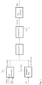
Figure 1 in the drawings shows a preferred embodiment of the present invention for generation of H2 and N2 streams for synthesizing green ammonia,
where compression step is performed, upstream to a joint oxygen removal from a combined stream of or H2 and N2. - The hydrogen stream from the electrolyzer typically contains 99.9 mole% H2 and 0.1 mole% O2. The nitrogen stream from the PSA unit typically contains 99.2 mole% N2, 0.3 mole% O2 and 0.5 mole% Ar as impurities.
- As mentioned hereinbefore, oxygen in ammonia synthesis gas will poison the ammonia catalyst and is therefore necessary to remove the oxygen contained in the hydrogen stream and in the nitrogen stream by catalytic hydrogenation of the oxygen to water.
- By the present invention the streams are combined in a molar ratio of H2 to N2 of about 2.8 to 3.2 and compressed in an upstream synthesis gas compressor and subsequently cleaned in hydrogenation unit.
- In the hydrogenation unit, oxygen will be removed by a catalyzed reaction with hydrogen to form water. Most of the water will be knocked out in an interstage cooling and separation before the thus prepared ammonia synthesis gas is introduced into a downstream ammonia loop.
Claims (8)
- Process for producing an ammonia synthesis gas comprising the steps of:(a) providing a separate stream comprising nitrogen by pressure swing absorption of ambient air;(b) providing a separate stream comprising hydrogen by electrolysis of water and/or steam;(c) combining the separate streams obtained in steps a) and b) into a mixed stream comprising hydrogen and nitrogen;(d) pressurizing the mixed stream from step (c); and(e) removing residual amounts of oxygen further contained in the mixed stream by catalytic hydrogenation of the oxygen with a part of the hydrogen contained in the mixed stream upstream step (d) and/or downstream step (d) and/or during step (d) to produce the ammonia synthesis gas, wherein the mixed stream comprising hydrogen and nitrogen is pressurized in an ammonia synthesis gas compressor upstream the catalytic hydrogenation.
- Process according to claim 1, wherein the mixed stream comprises hydrogen and nitrogen in an amount to provide a molar ratio of H2 to N2 of between 2.8 and 3.2.
- Process according to claims 1 or 2, wherein the electrolysis is performed in a solid oxide electrolysis cell.
- Process according to any one of claims 1 to 3, wherein the catalytic hydrogenation is performed in presence of hydrogenation catalyst.
- System for producing ammonia synthesis gas comprising:a) one or more pressure swing absorption units for providing a separate stream comprising nitrogen;b) one or more electrolysis units for providing a separate stream comprising hydrogen;c) combining means for providing a mixed stream comprising the separate hydrogen stream and the separate nitrogen stream;d) a compression unit for pressurizing the mixed stream; ande) an oxygen hydrogenation unit for the catalytic hydrogenation of oxygen contained in the pressurized mixed stream, wherein the compression unit is an ammonia synthesis gas compressor arranged upstream the hydrogenation unit.
- System according to claim 5, wherein the electrolysis unit is a solid oxide electrolysis cell.
- System according to claims 5 or 6, wherein the hydrogenation unit contains a hydrogenation catalyst.
- Plant comprising a system according to any one of claims 5 to 7, for operating a process according to any one of claims 1 to 4.
Applications Claiming Priority (2)
| Application Number | Priority Date | Filing Date | Title |
|---|---|---|---|
| DKPA202100819 | 2021-08-19 | ||
| PCT/EP2022/070321 WO2023020771A1 (en) | 2021-08-19 | 2022-07-20 | Process for the preparation of green ammonia synthesis gas |
Publications (2)
| Publication Number | Publication Date |
|---|---|
| EP4387925A1 EP4387925A1 (en) | 2024-06-26 |
| EP4387925B1 true EP4387925B1 (en) | 2025-06-11 |
Family
ID=82943071
Family Applications (1)
| Application Number | Title | Priority Date | Filing Date |
|---|---|---|---|
| EP22757215.3A Active EP4387925B1 (en) | 2021-08-19 | 2022-07-20 | Process for the preparation of green ammonia synthesis gas |
Country Status (14)
| Country | Link |
|---|---|
| US (1) | US20240351896A1 (en) |
| EP (1) | EP4387925B1 (en) |
| KR (1) | KR102897346B1 (en) |
| CN (1) | CN117836236A (en) |
| AR (1) | AR126797A1 (en) |
| AU (1) | AU2022330568A1 (en) |
| CA (1) | CA3227905A1 (en) |
| DK (1) | DK4387925T3 (en) |
| ES (1) | ES3040109T3 (en) |
| FI (1) | FI4387925T3 (en) |
| PL (1) | PL4387925T3 (en) |
| PT (1) | PT4387925T (en) |
| TW (1) | TW202308938A (en) |
| WO (1) | WO2023020771A1 (en) |
Families Citing this family (2)
| Publication number | Priority date | Publication date | Assignee | Title |
|---|---|---|---|---|
| EP4570759A1 (en) * | 2023-12-13 | 2025-06-18 | Linde GmbH | Method and installation for producing a process product |
| WO2025176298A1 (en) * | 2024-02-22 | 2025-08-28 | Oü Nordic Stream Group | A method for the synthesis of ammonia |
Family Cites Families (11)
| Publication number | Priority date | Publication date | Assignee | Title |
|---|---|---|---|---|
| US5320818A (en) * | 1992-12-22 | 1994-06-14 | Air Products And Chemicals, Inc. | Deoxygenation of non-cryogenically produced nitrogen with a hydrocarbon |
| US20050019244A1 (en) * | 2003-07-23 | 2005-01-27 | Spiegelman Jeffrey J. | Method for the point of use production of ammonia from water and nitrogen |
| US20130039833A1 (en) * | 2009-07-15 | 2013-02-14 | LiveFuels, Inc. | Systems and methods for producing ammonia fertilizer |
| EP2631213A1 (en) * | 2012-02-24 | 2013-08-28 | Ammonia Casale S.A. | Process for producing ammonia synthesis gas and a related front-end of an ammonia plant |
| US8992842B2 (en) * | 2012-04-17 | 2015-03-31 | Roger Gordon | Systems and methods of making ammonia using hydrogen and nitrogen gases |
| EP2930141A1 (en) * | 2014-04-08 | 2015-10-14 | Casale Sa | A method for revamping a front-end of an ammonia plant |
| CN106460568A (en) * | 2014-06-16 | 2017-02-22 | 西门子股份公司 | System and method for supplying energy from intermittent renewable energy sources to an energy grid |
| CN106185984B (en) * | 2016-07-23 | 2021-06-29 | 陈志强 | System for jointly producing ammonia and nitric acid based on steam electrolysis method |
| CN207046865U (en) * | 2017-06-22 | 2018-02-27 | 湖南高安新材料有限公司 | The device of high-purity ammon is prepared using hydrogen nitrogen mixed gas |
| UA126346C2 (en) * | 2017-07-25 | 2022-09-21 | Хальдор Топсьое А/С | METHOD OF OBTAINING GAS FOR AMMONIA SYNTHESIS |
| UA127164C2 (en) * | 2017-07-25 | 2023-05-24 | Хальдор Топсьое А/С | Method for the preparation of ammonia synthesis gas |
-
2022
- 2022-07-20 EP EP22757215.3A patent/EP4387925B1/en active Active
- 2022-07-20 ES ES22757215T patent/ES3040109T3/en active Active
- 2022-07-20 KR KR1020247004342A patent/KR102897346B1/en active Active
- 2022-07-20 FI FIEP22757215.3T patent/FI4387925T3/en active
- 2022-07-20 CN CN202280056649.8A patent/CN117836236A/en active Pending
- 2022-07-20 CA CA3227905A patent/CA3227905A1/en active Pending
- 2022-07-20 PT PT227572153T patent/PT4387925T/en unknown
- 2022-07-20 AU AU2022330568A patent/AU2022330568A1/en active Pending
- 2022-07-20 PL PL22757215.3T patent/PL4387925T3/en unknown
- 2022-07-20 US US18/683,747 patent/US20240351896A1/en active Pending
- 2022-07-20 WO PCT/EP2022/070321 patent/WO2023020771A1/en not_active Ceased
- 2022-07-20 DK DK22757215.3T patent/DK4387925T3/en active
- 2022-07-27 TW TW111128166A patent/TW202308938A/en unknown
- 2022-08-16 AR ARP220102200A patent/AR126797A1/en active IP Right Grant
Also Published As
| Publication number | Publication date |
|---|---|
| CN117836236A (en) | 2024-04-05 |
| DK4387925T3 (en) | 2025-08-25 |
| WO2023020771A1 (en) | 2023-02-23 |
| CA3227905A1 (en) | 2023-02-23 |
| EP4387925A1 (en) | 2024-06-26 |
| KR102897346B1 (en) | 2025-12-08 |
| PT4387925T (en) | 2025-08-14 |
| US20240351896A1 (en) | 2024-10-24 |
| AU2022330568A1 (en) | 2024-01-04 |
| TW202308938A (en) | 2023-03-01 |
| KR20240048512A (en) | 2024-04-15 |
| ES3040109T3 (en) | 2025-10-28 |
| PL4387925T3 (en) | 2025-10-20 |
| AR126797A1 (en) | 2023-11-15 |
| FI4387925T3 (en) | 2025-08-26 |
Similar Documents
| Publication | Publication Date | Title |
|---|---|---|
| EP3658493B1 (en) | Process for the co-production of methanol and ammonia | |
| EP3658489B1 (en) | Method for the preparation of ammonia synthesis gas | |
| CA2977239C (en) | Process for the ammonia production | |
| EP4387925B1 (en) | Process for the preparation of green ammonia synthesis gas | |
| EP2464601B1 (en) | Process for revamping an ammonia plant with nitrogen-based washing of a purge stream | |
| EP1390291A1 (en) | Syngas production utilizing an oxygen transport membrane | |
| WO2017075564A1 (en) | Increasing hydrogen recovery from co + h2 synthesis gas | |
| AU2004218179A1 (en) | Process and apparatus for the production of methanol | |
| EP4392368B1 (en) | Dual pressure system for producing nitric acid and method of operating thereof | |
| JPH06234517A (en) | Ammonia and methanol co-production method | |
| CN114502525B (en) | Method and apparatus for producing methanol from hydrogen-rich synthesis gas | |
| JP7816451B2 (en) | Ammonia production method and ammonia water production method | |
| EP3390279A1 (en) | A process for production of ammonia from inert-free synthesis gas in multiple reaction systems | |
| EA048748B1 (en) | METHOD OF OBTAINING SYNTHESIS GAS FOR THE PRODUCTION OF GREEN AMMONIA | |
| JP6946478B2 (en) | Increased capacity of existing units and processes to produce hydrogen from syngas in high yield | |
| US20240262770A1 (en) | Process for producing methanol from synthesis gas comprising a high proportion of inert gas components |
Legal Events
| Date | Code | Title | Description |
|---|---|---|---|
| STAA | Information on the status of an ep patent application or granted ep patent |
Free format text: STATUS: UNKNOWN |
|
| STAA | Information on the status of an ep patent application or granted ep patent |
Free format text: STATUS: THE INTERNATIONAL PUBLICATION HAS BEEN MADE |
|
| PUAI | Public reference made under article 153(3) epc to a published international application that has entered the european phase |
Free format text: ORIGINAL CODE: 0009012 |
|
| STAA | Information on the status of an ep patent application or granted ep patent |
Free format text: STATUS: REQUEST FOR EXAMINATION WAS MADE |
|
| 17P | Request for examination filed |
Effective date: 20240208 |
|
| AK | Designated contracting states |
Kind code of ref document: A1 Designated state(s): AL AT BE BG CH CY CZ DE DK EE ES FI FR GB GR HR HU IE IS IT LI LT LU LV MC MK MT NL NO PL PT RO RS SE SI SK SM TR |
|
| DAV | Request for validation of the european patent (deleted) | ||
| DAX | Request for extension of the european patent (deleted) | ||
| GRAP | Despatch of communication of intention to grant a patent |
Free format text: ORIGINAL CODE: EPIDOSNIGR1 |
|
| STAA | Information on the status of an ep patent application or granted ep patent |
Free format text: STATUS: GRANT OF PATENT IS INTENDED |
|
| RIC1 | Information provided on ipc code assigned before grant |
Ipc: C01C 1/04 20060101ALI20241129BHEP Ipc: C25B 15/08 20060101ALI20241129BHEP Ipc: C25B 1/042 20210101ALI20241129BHEP Ipc: C01B 21/04 20060101ALI20241129BHEP Ipc: C01B 3/02 20060101AFI20241129BHEP |
|
| INTG | Intention to grant announced |
Effective date: 20250107 |
|
| GRAS | Grant fee paid |
Free format text: ORIGINAL CODE: EPIDOSNIGR3 |
|
| GRAA | (expected) grant |
Free format text: ORIGINAL CODE: 0009210 |
|
| STAA | Information on the status of an ep patent application or granted ep patent |
Free format text: STATUS: THE PATENT HAS BEEN GRANTED |
|
| AK | Designated contracting states |
Kind code of ref document: B1 Designated state(s): AL AT BE BG CH CY CZ DE DK EE ES FI FR GB GR HR HU IE IS IT LI LT LU LV MC MK MT NL NO PL PT RO RS SE SI SK SM TR |
|
| REG | Reference to a national code |
Ref country code: GB Ref legal event code: FG4D |
|
| REG | Reference to a national code |
Ref country code: CH Ref legal event code: EP |
|
| REG | Reference to a national code |
Ref country code: DE Ref legal event code: R096 Ref document number: 602022015865 Country of ref document: DE |
|
| REG | Reference to a national code |
Ref country code: IE Ref legal event code: FG4D |
|
| P01 | Opt-out of the competence of the unified patent court (upc) registered |
Free format text: CASE NUMBER: APP_31864/2025 Effective date: 20250702 |
|
| REG | Reference to a national code |
Ref country code: PT Ref legal event code: SC4A Ref document number: 4387925 Country of ref document: PT Date of ref document: 20250814 Kind code of ref document: T Free format text: AVAILABILITY OF NATIONAL TRANSLATION Effective date: 20250808 |
|
| REG | Reference to a national code |
Ref country code: DK Ref legal event code: T3 Effective date: 20250818 |
|
| REG | Reference to a national code |
Ref country code: FI Ref legal event code: FGE |
|
| REG | Reference to a national code |
Ref country code: SE Ref legal event code: TRGR |
|
| REG | Reference to a national code |
Ref country code: NL Ref legal event code: FP |
|
| PGFP | Annual fee paid to national office [announced via postgrant information from national office to epo] |
Ref country code: NL Payment date: 20250825 Year of fee payment: 4 |
|
| PGFP | Annual fee paid to national office [announced via postgrant information from national office to epo] |
Ref country code: ES Payment date: 20250812 Year of fee payment: 4 Ref country code: PT Payment date: 20250813 Year of fee payment: 4 Ref country code: FI Payment date: 20250825 Year of fee payment: 4 |
|
| PGFP | Annual fee paid to national office [announced via postgrant information from national office to epo] |
Ref country code: DE Payment date: 20250808 Year of fee payment: 4 Ref country code: DK Payment date: 20250825 Year of fee payment: 4 |
|
| REG | Reference to a national code |
Ref country code: LT Ref legal event code: MG9D |
|
| PG25 | Lapsed in a contracting state [announced via postgrant information from national office to epo] |
Ref country code: GR Free format text: LAPSE BECAUSE OF FAILURE TO SUBMIT A TRANSLATION OF THE DESCRIPTION OR TO PAY THE FEE WITHIN THE PRESCRIBED TIME-LIMIT Effective date: 20250912 |
|
| PGFP | Annual fee paid to national office [announced via postgrant information from national office to epo] |
Ref country code: NO Payment date: 20250819 Year of fee payment: 4 |
|
| PGFP | Annual fee paid to national office [announced via postgrant information from national office to epo] |
Ref country code: TR Payment date: 20250902 Year of fee payment: 4 Ref country code: IT Payment date: 20250731 Year of fee payment: 4 |
|
| PG25 | Lapsed in a contracting state [announced via postgrant information from national office to epo] |
Ref country code: BG Free format text: LAPSE BECAUSE OF FAILURE TO SUBMIT A TRANSLATION OF THE DESCRIPTION OR TO PAY THE FEE WITHIN THE PRESCRIBED TIME-LIMIT Effective date: 20250611 |
|
| PG25 | Lapsed in a contracting state [announced via postgrant information from national office to epo] |
Ref country code: HR Free format text: LAPSE BECAUSE OF FAILURE TO SUBMIT A TRANSLATION OF THE DESCRIPTION OR TO PAY THE FEE WITHIN THE PRESCRIBED TIME-LIMIT Effective date: 20250611 |
|
| PGFP | Annual fee paid to national office [announced via postgrant information from national office to epo] |
Ref country code: AT Payment date: 20251020 Year of fee payment: 4 Ref country code: FR Payment date: 20250818 Year of fee payment: 4 |
|
| PGFP | Annual fee paid to national office [announced via postgrant information from national office to epo] |
Ref country code: SE Payment date: 20250825 Year of fee payment: 4 Ref country code: CH Payment date: 20250825 Year of fee payment: 4 |
|
| PG25 | Lapsed in a contracting state [announced via postgrant information from national office to epo] |
Ref country code: RS Free format text: LAPSE BECAUSE OF FAILURE TO SUBMIT A TRANSLATION OF THE DESCRIPTION OR TO PAY THE FEE WITHIN THE PRESCRIBED TIME-LIMIT Effective date: 20250911 |
|
| REG | Reference to a national code |
Ref country code: ES Ref legal event code: FG2A Ref document number: 3040109 Country of ref document: ES Kind code of ref document: T3 Effective date: 20251028 |
|
| PG25 | Lapsed in a contracting state [announced via postgrant information from national office to epo] |
Ref country code: LV Free format text: LAPSE BECAUSE OF FAILURE TO SUBMIT A TRANSLATION OF THE DESCRIPTION OR TO PAY THE FEE WITHIN THE PRESCRIBED TIME-LIMIT Effective date: 20250611 |
|
| REG | Reference to a national code |
Ref country code: AT Ref legal event code: MK05 Ref document number: 1802225 Country of ref document: AT Kind code of ref document: T Effective date: 20250611 |
|
| PG25 | Lapsed in a contracting state [announced via postgrant information from national office to epo] |
Ref country code: IS Free format text: LAPSE BECAUSE OF FAILURE TO SUBMIT A TRANSLATION OF THE DESCRIPTION OR TO PAY THE FEE WITHIN THE PRESCRIBED TIME-LIMIT Effective date: 20251011 |
|
| PG25 | Lapsed in a contracting state [announced via postgrant information from national office to epo] |
Ref country code: AT Free format text: LAPSE BECAUSE OF FAILURE TO SUBMIT A TRANSLATION OF THE DESCRIPTION OR TO PAY THE FEE WITHIN THE PRESCRIBED TIME-LIMIT Effective date: 20250611 Ref country code: SM Free format text: LAPSE BECAUSE OF FAILURE TO SUBMIT A TRANSLATION OF THE DESCRIPTION OR TO PAY THE FEE WITHIN THE PRESCRIBED TIME-LIMIT Effective date: 20250611 |
|
| PG25 | Lapsed in a contracting state [announced via postgrant information from national office to epo] |
Ref country code: CZ Free format text: LAPSE BECAUSE OF FAILURE TO SUBMIT A TRANSLATION OF THE DESCRIPTION OR TO PAY THE FEE WITHIN THE PRESCRIBED TIME-LIMIT Effective date: 20250611 |
|
| PGFP | Annual fee paid to national office [announced via postgrant information from national office to epo] |
Ref country code: PL Payment date: 20250814 Year of fee payment: 4 |
|
| PG25 | Lapsed in a contracting state [announced via postgrant information from national office to epo] |
Ref country code: EE Free format text: LAPSE BECAUSE OF FAILURE TO SUBMIT A TRANSLATION OF THE DESCRIPTION OR TO PAY THE FEE WITHIN THE PRESCRIBED TIME-LIMIT Effective date: 20250611 |
|
| PG25 | Lapsed in a contracting state [announced via postgrant information from national office to epo] |
Ref country code: SK Free format text: LAPSE BECAUSE OF FAILURE TO SUBMIT A TRANSLATION OF THE DESCRIPTION OR TO PAY THE FEE WITHIN THE PRESCRIBED TIME-LIMIT Effective date: 20250611 |
|
| PG25 | Lapsed in a contracting state [announced via postgrant information from national office to epo] |
Ref country code: RO Free format text: LAPSE BECAUSE OF FAILURE TO SUBMIT A TRANSLATION OF THE DESCRIPTION OR TO PAY THE FEE WITHIN THE PRESCRIBED TIME-LIMIT Effective date: 20250611 |
|
| REG | Reference to a national code |
Ref country code: DE Ref legal event code: R097 Ref document number: 602022015865 Country of ref document: DE |
|
| PG25 | Lapsed in a contracting state [announced via postgrant information from national office to epo] |
Ref country code: LU Free format text: LAPSE BECAUSE OF NON-PAYMENT OF DUE FEES Effective date: 20250720 |
|
| REG | Reference to a national code |
Ref country code: BE Ref legal event code: MM Effective date: 20250731 |
|
| PG25 | Lapsed in a contracting state [announced via postgrant information from national office to epo] |
Ref country code: MC Free format text: LAPSE BECAUSE OF FAILURE TO SUBMIT A TRANSLATION OF THE DESCRIPTION OR TO PAY THE FEE WITHIN THE PRESCRIBED TIME-LIMIT Effective date: 20250611 |
|
| PG25 | Lapsed in a contracting state [announced via postgrant information from national office to epo] |
Ref country code: BE Free format text: LAPSE BECAUSE OF NON-PAYMENT OF DUE FEES Effective date: 20250731 |
|
| PLBE | No opposition filed within time limit |
Free format text: ORIGINAL CODE: 0009261 |
|
| STAA | Information on the status of an ep patent application or granted ep patent |
Free format text: STATUS: NO OPPOSITION FILED WITHIN TIME LIMIT |
|
| REG | Reference to a national code |
Ref country code: CH Ref legal event code: L10 Free format text: ST27 STATUS EVENT CODE: U-0-0-L10-L00 (AS PROVIDED BY THE NATIONAL OFFICE) Effective date: 20260423 |