EP4387266A1 - Speaker device with bistable active vent - Google Patents
Speaker device with bistable active vent Download PDFInfo
- Publication number
- EP4387266A1 EP4387266A1 EP23217139.7A EP23217139A EP4387266A1 EP 4387266 A1 EP4387266 A1 EP 4387266A1 EP 23217139 A EP23217139 A EP 23217139A EP 4387266 A1 EP4387266 A1 EP 4387266A1
- Authority
- EP
- European Patent Office
- Prior art keywords
- blocking mechanism
- closed state
- speaker device
- ear canal
- user
- Prior art date
- Legal status (The legal status is an assumption and is not a legal conclusion. Google has not performed a legal analysis and makes no representation as to the accuracy of the status listed.)
- Pending
Links
Images




Classifications
-
- H—ELECTRICITY
- H04—ELECTRIC COMMUNICATION TECHNIQUE
- H04R—LOUDSPEAKERS, MICROPHONES, GRAMOPHONE PICK-UPS OR LIKE ACOUSTIC ELECTROMECHANICAL TRANSDUCERS; ELECTRIC HEARING AIDS; PUBLIC ADDRESS SYSTEMS
- H04R1/00—Details of transducers, loudspeakers or microphones
- H04R1/20—Arrangements for obtaining desired frequency or directional characteristics
- H04R1/22—Arrangements for obtaining desired frequency or directional characteristics for obtaining desired frequency characteristic only
-
- H—ELECTRICITY
- H04—ELECTRIC COMMUNICATION TECHNIQUE
- H04R—LOUDSPEAKERS, MICROPHONES, GRAMOPHONE PICK-UPS OR LIKE ACOUSTIC ELECTROMECHANICAL TRANSDUCERS; ELECTRIC HEARING AIDS; PUBLIC ADDRESS SYSTEMS
- H04R9/00—Transducers of moving-coil, moving-strip, or moving-wire type
- H04R9/06—Loudspeakers
-
- H—ELECTRICITY
- H04—ELECTRIC COMMUNICATION TECHNIQUE
- H04R—LOUDSPEAKERS, MICROPHONES, GRAMOPHONE PICK-UPS OR LIKE ACOUSTIC ELECTROMECHANICAL TRANSDUCERS; ELECTRIC HEARING AIDS; PUBLIC ADDRESS SYSTEMS
- H04R1/00—Details of transducers, loudspeakers or microphones
- H04R1/10—Earpieces; Attachments therefor ; Earphones; Monophonic headphones
- H04R1/1016—Earpieces of the intra-aural type
-
- H—ELECTRICITY
- H04—ELECTRIC COMMUNICATION TECHNIQUE
- H04R—LOUDSPEAKERS, MICROPHONES, GRAMOPHONE PICK-UPS OR LIKE ACOUSTIC ELECTROMECHANICAL TRANSDUCERS; ELECTRIC HEARING AIDS; PUBLIC ADDRESS SYSTEMS
- H04R25/00—Electric hearing aids
- H04R25/45—Prevention of acoustic reaction, i.e. acoustic oscillatory feedback
- H04R25/456—Prevention of acoustic reaction, i.e. acoustic oscillatory feedback mechanically
-
- H—ELECTRICITY
- H04—ELECTRIC COMMUNICATION TECHNIQUE
- H04R—LOUDSPEAKERS, MICROPHONES, GRAMOPHONE PICK-UPS OR LIKE ACOUSTIC ELECTROMECHANICAL TRANSDUCERS; ELECTRIC HEARING AIDS; PUBLIC ADDRESS SYSTEMS
- H04R9/00—Transducers of moving-coil, moving-strip, or moving-wire type
- H04R9/02—Details
-
- H—ELECTRICITY
- H04—ELECTRIC COMMUNICATION TECHNIQUE
- H04R—LOUDSPEAKERS, MICROPHONES, GRAMOPHONE PICK-UPS OR LIKE ACOUSTIC ELECTROMECHANICAL TRANSDUCERS; ELECTRIC HEARING AIDS; PUBLIC ADDRESS SYSTEMS
- H04R1/00—Details of transducers, loudspeakers or microphones
- H04R1/10—Earpieces; Attachments therefor ; Earphones; Monophonic headphones
- H04R1/1041—Mechanical or electronic switches, or control elements
-
- H—ELECTRICITY
- H04—ELECTRIC COMMUNICATION TECHNIQUE
- H04R—LOUDSPEAKERS, MICROPHONES, GRAMOPHONE PICK-UPS OR LIKE ACOUSTIC ELECTROMECHANICAL TRANSDUCERS; ELECTRIC HEARING AIDS; PUBLIC ADDRESS SYSTEMS
- H04R2400/00—Loudspeakers
- H04R2400/11—Aspects regarding the frame of loudspeaker transducers
-
- H—ELECTRICITY
- H04—ELECTRIC COMMUNICATION TECHNIQUE
- H04R—LOUDSPEAKERS, MICROPHONES, GRAMOPHONE PICK-UPS OR LIKE ACOUSTIC ELECTROMECHANICAL TRANSDUCERS; ELECTRIC HEARING AIDS; PUBLIC ADDRESS SYSTEMS
- H04R2460/00—Details of hearing devices, i.e. of ear- or headphones covered by H04R1/10 or H04R5/033 but not provided for in any of their subgroups, or of hearing aids covered by H04R25/00 but not provided for in any of its subgroups
- H04R2460/11—Aspects relating to vents, e.g. shape, orientation, acoustic properties in ear tips of hearing devices to prevent occlusion
Definitions
- the invention relates to a speaker device with a bistable active vent for reduction of the occlusion effect.
- earbuds or hearing aids Users of hearing devices, such as earbuds or hearing aids, often experience occlusion, when the ear canal is blocked by the device. This is caused by a build-up of sound pressure in the ear canal. Sounds at low frequencies, such as the user's own voice or chewing sounds, are particularly pronounced, which can be highly annoying for the user.
- the hearing device can be provided with a vent which provides fluid connection between the ear canal and the outside of the ear canal. This allows the sound pressure in the ear canal to me reduced and the occlusion effect lessened. This however is not always an advantage, since the user in some cases benefits from a high sound pressure, for example if the user wants a more powerful bass when listening to music, or if a hearing aid user needs extra amplification of sound.
- the hearing device can be provided with an active vent, which can be opened when a reduction of the occlusion effect is desired and closed when a greater sound pressure is desired.
- An active vent comprises a blocking device configured for selectively blocking the vent, thereby preventing fluid connection through the vent, or opening the vent to reduce the occlusion effect.
- a problem in existing active vents is that the blocking device is not actively held in place in the intended position, i.e. open or closed, but is instead passively fixated by friction forces after being driven to the desired position.
- a reason for this is that the energy consumption is increased by actively fixating the blocking device, and it is almost always desired to keep energy consumption low, particularly for hearing aids, which are designed to be as small as possible and have as long operational time on a battery charge as possible.
- the blocking device is passively fixated, the user risks that the blocking device changes position if the hearing device is subjected to external forces, such as dropping the hearing device. Additionally, the friction is reduced over time, which further increases the risk of the blocking device changing its intended position.
- a speaker device adapted to be worn at least partially in a user's ear canal
- the speaker device comprises a speaker and an active vent to reduce occlusion of the ear canal
- the vent comprises a passage that is adapted to providing fluid connection between the ear canal and the user's surroundings when the speaker device is placed in the ear canal, and a blocking mechanism having a closed state in which the blocking mechanism at least partially blocks the passage, and an open state in which the blocking mechanism blocks the passage less than in the closed state
- the active vent further comprises a bistable device adapted to hold the blocking mechanism in the open state and in the closed state, where the bistable device is unstable when the blocking mechanism is between the open and the closed state.
- unstable In this context, unstable must be understood as meaning that the blocking mechanism in positions between the open and closed state will be driven towards one of the two states by a passive force, e.g. of a permanent magnet, a spring or material stresses, meaning that the blocking mechanism will be in a potential energy well in the open and the closed state and will have to cross an energy barrier to change state.
- a passive force e.g. of a permanent magnet, a spring or material stresses
- a potential energy configuration can be provided in different ways.
- An advantage of the invention is that the bistable device will be stable when the blocking mechanism is in the open or closed state and will have to cross an energy barrier to move between the two, preventing sudden, unwanted switching between states or the blocking mechanism drifting between the open and the closed state.
- the user will thus achieve greater operational reliability.
- the vent according to the invention will be able to find use in devices that during use block the user's ear canal, so that occlusion can occur.
- Such devices can be hearing devices designed to create sound in the user's ear canal, e.g. earphones and hearing aids, but it can also be passive devices such as earplugs and hearing protectors.
- the speaker device can be a headphone configured for placement in a user's ear canal and at the opening of the ear canal.
- the hearing device can be a hearing aid configured to be placed behind a user's ear and/or in a user's ear canal.
- hearing aid is understood a hearing device designed to pick up sounds with microphones, make an output sound signal from the picked up sounds by compensating for a user's hearing loss by and reproduce the output sound signal to the user with a loudspeaker and/or a cochlear implant.
- the speaker device may be a hearing aid of the BTE [Behind The Ear] type, comprising a housing designed to be placed behind the user's ear, where the speaker for reproducing the output audio signal is located in the housing, and the sound from there is brought to the user's ear canal through a hollow sound tube.
- the hearing aid may be of the RIE [Receiver In Ear] type, comprising a BTE component with a housing adapted to be placed behind the user's ear, and a speaker device according to the invention coupled to the BTE component, where the speaker for reproducing output the audio signal is located in the speaker device and the output signal is carried from the BTE component to the speaker device through an electrically conductive cable.
- the hearing aid can be of the type ITE [In The Ear] or CIC [Completely In Canal], which include a housing to be placed fully or partially in the user's ear canal, where the loudspeaker for reproduction of the output sound signal is placed in the housing.
- the speaker device of the second aspect of the invention may be a speaker device for an RIE hearing aid.
- the speaker device may be arranged to be coupled with the BTE component of a hearing aid.
- the active vent according to the invention will be able to be used in any device that blocks the user's ear canal and thereby creates an occlusion effect.
- the blocking mechanism can have a center position, where the bistable device drives the blocking mechanism towards the open state when the blocking mechanism is between the open state and the center position, and towards the closed state when the blocking mechanism is between the center position and the closed state.
- the active vent may include an electronic actuator.
- the electronic actuator may comprise a magnetic material comprising a permanent magnet, a paramagnetic material, a ferromagnetic material and/or a ferrimagnetic material, and an electromagnet, which in cooperation are configured to, upon activation, drive the blocking mechanism towards the open state or towards the closed state.
- One of the magnetic material and the electromagnet is movable, relative to the passage, on the blocking mechanism, and the other is arranged immovable, relative to the passage, so that when activated, the electromagnet will be able to attract or repel the magnetic material and thereby change the state of the blocking mechanism.
- the electromagnet is positioned immovably relative to the passage and the magnetic material is attached to the blocking mechanism so that the magnetic material is movable relative to the passage.
- the active vent may comprise a mechanical actuator adapted to move the blocking mechanism between the open and the closed state.
- the mechanical actuator may comprise a mechanical interface, such as a push button, a rotary switch and/or a sliding switch, which is arranged to, upon activation by the user, move the blocking mechanism between states.
- the advantage of a mechanical actuator will be that the extractor will not need electrical energy to move between the open state and the closed state and will thereby be able to operate with lower energy consumption.
- the bistable device comprises a buckling element.
- the buckling element is configured to have a first stable shape and a second stable shape and to be able to change between the first and the second stable shape through temporary mechanical deformation, during which mechanical deformation the buckling element is unstable.
- the blocking mechanism is in the open state
- the bulging element is in its second stable shape
- the blocking mechanism is in the closed state.
- a buckling element in the invention is particularly advantageous in that the blocking mechanism will be able to be held securely in each of the open and closed states, at the same time that a buckling element can be easily designed so that the force required to bring it through the temporary mechanical deformation between the stable forms, is low enough that it can be provided by a small electromagnet or the like, but not so low that spontaneous changes between the two forms will be a risk, e.g. if the user were to drop the speaker device.
- the bistable device may comprise a first biasing element that is adapted to drive the blocking mechanism towards the open state, and/or a second incentive element that is adapted to drive the blocking mechanism towards the closed state.
- Each of the first and second biasing elements may comprise a spring and/or a magnet.
- the first biasing element may be arranged to exert a first force on the blocking mechanism, which first force drives the blocking mechanism towards the open state. The magnitude of the first force may be dependent on the position of the blocking mechanism.
- the second biasing element may be arranged to exert a second force on the blocking mechanism, which second force drives the blocking mechanism towards the closed state. The magnitude of the second force may be dependent on the position of the blocking mechanism.
- the first force may be greater than the second force when the blocking mechanism is between the open state and the center position.
- the second force may be greater than the first force when the blocking mechanism is between the closed state and the center position.
- the blocking mechanism may comprise a plunger which is linearly movable between the open and closed states.
- the blocking mechanism may comprise a disc which is rotatably movable between the open and closed states.
- the blocking mechanism may comprise a diaphragm that can be bent between the open and the closed state.
- the speaker device may comprise a sealing element that is configured to seal the inside of the ear canal from the user's surroundings when the speaker device is placed in the ear canal.
- the sealing element may be provided by a silicone element or an element of a material with compression properties similar to silicone.
- the sealing element can be shaped like a dome.
- the sealing element can be removable so that the user can change it without the use of tools.
- Fig. 1a-f show a speaker device 100 according to the prior art.
- the speaker device 100 is configured to be placed at least partially in a user's ear canal and to be connected to a BTE component 200 of a hearing aid of the type Receiver In Ear, RIE.
- the speaker device 100 comprises a housing 160 with a distal end 180 that is arranged to face the user's eardrum when the speaker device 100 is arranged in the ear canal, and a proximal end 190 that is arranged to face away from the ear canal when the speaker device 100 is arranged in the ear canal.
- the housing 160 houses a speaker 140, which is arranged to receive an electrical input signal and convert it into an acoustic output signal for the user.
- the speaker device 100 comprises a coupling element 130 with an electric wire, which coupling element 130 is designed to connect the speaker device 100 to the BTE component 300.
- the housing comprises a neck 110 in the form of a cylinder which, during use, protrudes into the ear canal.
- the cylinder has a cavity 150 so that, during use, a fluid connection is provided between the inside of the housing 160 and the distal end 190, and thereby the speaker 140 and the ear canal, so that the speaker 140 can generate an acoustic output signal that is sent into the ear canal.
- the speaker device 100 comprises a sealing element 170.
- the sealing element 170 comprises a hollow cylinder which is attached to a fastening flange 120 which is formed on the neck 110.
- the sealing element 170 further comprises a dome of a flexible material, such as silicone, which during use rests against the user's ear canal and through friction with the ear canal holds the speaker device 100 in place.
- the sealing element 170 has the additional function of sealing the ear canal at least partially from the surroundings, i.e. the outside of the user's ear canal, so that a greater sound pressure can be achieved during use of the speaker device 100.
- the disadvantage of this is that an occlusion effect is simultaneously created, where sounds from the user's body, e.g. speech or vibrations are amplified in the ear canal due to the seal, which can feel uncomfortable for the user.
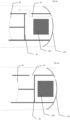
- Fig. 2a and 2b show a speaker device 100 according to the invention.
- the speaker device 100 includes an active vent.
- the active vent includes a passage 10 which is designed to create a fluid connection between the ear canal, i.e. the part of the ear canal which is sealed by the sealing element 170, and the user's surroundings, i.e. the opposite side of the seal, so that a drain is provided for the sound pressure in the ear canal, thereby reducing the occlusion.
- the active vent further comprises a blocking mechanism 20 having a closed state in which the blocking mechanism 20 blocks the passage 10 in whole or in part, and an open state in which the blocking mechanism 20 blocks the passage 10 less than in the closed state. This provides the possibility of selectively choosing the open mode, if it is necessary to reduce the occlusion effect, or the closed mode, if a greater sound pressure is needed.
- the active vent further comprises a bistable element 30 which is designed to hold the blocking mechanism 20 in the open state and in the closed state, where the bistable device 30 is unstable when the blocking mechanism 20 is between the open and the closed state.
- bistable device 30 is described in further detail below.
- the passage 10 runs through the housing 160 and connects the cavity 150 of the neck 110 with the proximal end 190.
- the cavity 150 forms part of the passage 10, so that the passage 10 provides fluid connection between the two sides of the sealing element 170.
- the blocking mechanism is arranged near the proximal 190, but it could be arranged anywhere along the passage 10.
- the neck 110 is provided with an opening that connects the cavity 150 with the outside of the housing 160.
- the passage 10 is provided by the cavity 170, the distal end 180 being in fluid connection with the outside of the sealing element 170 through the cavity 170 and the opening in the neck 110
- the blocking mechanism is arranged at the opening in the neck so that the area of the opening can be limited or blocked, whereby the fluid connection between the two sides of the sealing element 170 can be controlled.
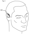
- Fig. 3 shows how a hearing device comprising a BTE component 300 and a speaker device 100 according to the invention is placed on the user.
- the BTE component 300 is worn behind the user's ear, while the speaker device 100 is arranged in the user's ear canal, and therefore cannot be seen in Fig. 3 .
- Fig. 4a and 4b show a speaker device 100 according to the invention with the blocking mechanism 20 in the open state and the closed state, respectively.
- the speaker device 100 comprises a speaker 140 which is arranged to convert an electrical input signal into an acoustic output signal, a sealing element 170 which is arranged to seal the inside of the ear canal from the surroundings when the speaker device 100 is placed in the ear canal.
- the active vent comprises a passage 10 that extends between an opening in the sealing element 170 and an opening in the housing 160, so that a fluid connection is provided between the two sides of the sealing element.
- the active vent further comprises a blocking element 20 which is linearly displaceable between a closed state in which the blocking mechanism 20 is pushed forward so that the passage 10 is blocked, and an open state in which the blocking mechanism 20 is retracted so that the passage 10 is not blocked.
- the active vent further comprises a bistable device 30 connected to the blocking mechanism 20, in the form of a buckling element, which is unstable when the blocking mechanism 20 is not in the open state or the closed state, i.e. when the blocking mechanism 20 is between the open state and the closed state.
- the buckling element has a first stable shape and a second stable shape, and the buckling element can be changed between the stable shapes by temporary deformation.
- the buckling element is configured to counteract this deformation, so that the buckling element drives the blocking mechanism 20 towards the open state when the blocking mechanism 20 is between the open state and the center position.
- the buckling element drives the blocking mechanism 20 toward the closed state when the blocking mechanism 20 is between the closed state and the center position.
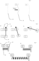
- Fig. 5 shows a buckling element for use in the bistable device according to the invention in three different states, 1), 2), and 3), corresponding respectively to the open state, the center position, i.e. a state between the open and the closed state, and the closed state.
- the buckling element is tensioned, so that in state 1), i.e. the bulge element's first stable shape, buckles out to one side, and that in state 3), i.e. the second stable shape of the buckling element, buckles out to another side, while in state 2) the buckling element undergoes deformation through a force effect, so that it can change between the stable shapes.
- an activation mechanism can be provided which is arranged to exert an external force on the blocking mechanism in the direction towards the open and/or the closed state, e.g. in the form of an electronic actuator with an electromagnet or a mechanical actuator with a push button, which is arranged to transfer a pressure from the user to the blocking mechanism 20.
- Fig. 6 shows a magnetic bistable device according to the invention in three different states, 1), 2), and 3), corresponding respectively to the open state, a center position, i.e. a state between the open and the closed state, and the closed state.
- the blocking mechanism 20 is rotatably mounted to a pivot point so that it can be rotated between states 1) and 3).
- the magnetic bistable device comprises a first biasing element 40 which is configured to drive the blocking mechanism 20 towards the open state, and a second biasing element 50 which is configured to drive the blocking mechanism towards the closed state.
- the first biasing element 40 comprises a set of permanent magnets which are arranged to repel each other, with one magnet connected to the blocking mechanism 20, thereby providing a force which drives the blocking mechanism 20 towards the open state.
- the second biasing element 50 comprises a set of permanent magnets arranged to attract each other, with one magnet connected to the blocking mechanism 20, thereby providing a force which drives the blocking mechanism 20 towards the closed state.
- the first biasing element 40 is arranged closer to the pivot point than the second biasing element 50, which means that the second biasing element 50 affects the blocking mechanism 20 with a greater torque than the first biasing element 40 when the blocking mechanism is in the closed state, so that the blocking mechanism is maintained in the closed state.
- the blocking mechanism 20 is rotated towards the open state, the distance between the magnets in the first biasing element 40 will decrease less than the distance between the magnets in the second biasing element 50, the second biasing element being arranged further from the pivot point.
- an activation mechanism can be provided which is configured to exert an external force on the blocking mechanism in the direction towards the open and/or the closed state, e.g. in the form of an electronic actuator with an electromagnet or a mechanical actuator with a push button, which is arranged to transfer a pressure from the user to the blocking mechanism 20.
- Fig.7 shows a spring/magnetic bistable device according to the invention in three different states, 1), 2), and 3), corresponding respectively to the open state, the center position, and the closed state.
- the spring/magnetic bistable device comprises a first biasing element 40 which is adapted to drive the blocking mechanism 20 towards the open state, and a second biasing element 50 which is adapted to drive the blocking mechanism 20 towards the closed state.
- the first biasing member 40 comprises a spring which is more compressed when the blocking mechanism 20 is in the closed state 20 than when the blocking mechanism 20 is in the closed open 20, thereby providing a force that drives the blocking mechanism 20 towards the open state.
- the second biasing element 50 comprises a set of permanent magnets arranged to attract each other, one magnet being connected to the blocking mechanism 20, thereby providing a force which drives the blocking mechanism 20 towards the closed state.
- the first and second biasing elements 40, 50 are arranged so that the attractive force between the magnets is greater than the spring force when the blocking element 20 is in the closed state and between the closed state and the center position. Since the magnetic attraction is dependent on the distance between the magnets to the minus third power, while the spring force is linear, the attraction force from the magnets will decrease more than the force from the compressed spring when the blocking mechanism 20 is moved from the closed state to the open state. Between the center position and the open state, the magnetic attraction force from the second biasing element 50 will be reduced so much that it will be less than the spring force from the first biasing element 40, from which the spring force will be dominant in pushing the blocking mechanism 20 to the open state.
- an activation mechanism can be provided which is arranged to exert an external force on the blocking mechanism in the direction towards the open and/or the closed state, e.g. in the form of an electronic actuator with an electromagnet or a mechanical actuator with a push button, which is arranged to transfer a pressure from the user to the blocking mechanism 20.
- bistable devices than those shown can be provided by using other configurations of incentive elements comprising one or more springs and/or one or more sets of magnets arranged so that the force from the first biasing element 40 on the blocking mechanism 20 will be greater than the force from the second biasing element 50 when the blocking mechanism is between the open state and the center position, and also that the force from the first biasing element 40 on the blocking mechanism 20 will be less than the force from the second biasing element 50 when the blocking mechanism is between the closed state and the center position.
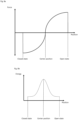
- Fig. 8a shows a force diagram illustrating the force which a bistable device according to the invention exerts on the blocking mechanism depending on the position of the blocking element.
- the force will be negative, corresponding to a force directed towards the closed state.
- the force will be positive, corresponding to a force directed towards the open state. In the two stable states the force goes to zero, as the bistable device is stable in these states.
- Fig. 8b shows an energy diagram illustrating the potential energy of the blocking mechanism 20 connected to a bistable device according to the invention.
- the blocking mechanism 20 will be in an energy well when the blocking mechanism 20 is in the open state and in the closed state. To be moved between the two states, the energy barrier between the two energy wells must be overcome.
- Fig. 9a-h show a speaker device 200 according to the invention in the form of an earphone.
- the speaker device 200 comprises a housing 260 with a distal end 280 that is arranged to face the user's eardrum when the speaker device 200 is arranged in the ear canal, and a proximal end 290 that is arranged to face away from the ear canal when the speaker device 200 is arranged in the ear canal.
- the housing 260 contains a speaker 240 which is arranged to receive an electrical input signal and convert it into an acoustic output signal for the user.
- the housing includes a neck 210 in the form of a cylinder that protrudes into the ear canal during use.
- the cylinder has a cavity 250 so that, during use, a fluid connection is provided between the inside of the housing 260 and the distal end 290, and thereby the speaker 240 and the ear canal, so that the speaker 140 can generate an acoustic output signal that is sent into the ear canal.
- the speaker device 200 comprises a sealing element 270.
- the sealing element 270 comprises a hollow cylinder which is attached to a fastening flange 220 which is formed on the neck 210.
- the sealing element 270 comprises a hollow cylinder 272 with a base 273 which is adapted to engage with fastening flanges 220 so that the sealing element 270 can be attached to the housing 260.
- the sealing element 270 further comprises a dome 271 of a flexible material such as silicone, which during use rests against the user's ear canal and through friction with the ear canal holds the speaker device 200 in place.
- the sealing element 270 has the additional function of sealing the ear canal at least partially from the surroundings, i.e. the outside of the user's ear canal, so that a greater sound pressure can be achieved during use of the speaker device 200.
- the speaker device 200 has an active vent comprising a passage 10.
- the passage 10 is provided by a recess formed in the housing 260, the neck 210 and the attachment flange 220.
- the recess extends between an internal opening 12 in the form of a through hole connecting the recess with the cavity 250 in the neck 210, and an outer opening 11 at the base of the neck 210.
- the sealing element 270 is mounted on the fastening flange 220, the recess is covered so that a closed channel is formed that connects the two sides of the seal of the ear canal, thereby forming fluid connection between the ear canal and the surroundings when the speaker device 200 is placed in the user's ear.
- the active vent further comprises a blocking mechanism 20 and a bistable device arranged so that the blocking mechanism 20 can close the passage 20 at least partially.
- Fig. 10 shows a speaker device according to the invention similar to that shown in Fig. 9a-h .
- This embodiment differs from that of Fig. 9a-h .
- the blocking mechanism 20 is provided by a hollow cylinder arranged concentrically with the neck 210.
- the blocking mechanism 20 is linearly displaceable along the longitudinal axis (z) of the neck so that the blocking mechanism can be displaced forward towards the distal end 280 where it at least partially blocks it through hole 20 that connects the cavity 250 of the neck with the recess. This blocks or reduces the fluid connection, the passage 10 being at least partially closed.
- the blocking mechanism can also be moved linearly back towards the proximal end 290, where it blocks the through hole less than in the closed state or does not cover the through hole 20 at all. This provides the fluid connection, as the blocking mechanism 20 exposes the passage 10, thereby opening it.
- the bistable device 30 is provided by a first biasing element 40 comprising a first permanent magnet, a second biasing element 50 comprising a second permanent magnet and a third permanent magnet.
- the third permanent magnet is attached to the blocking mechanism 20 so that it is linearly displaceable together with the blocking mechanism 20.
- the first permanent magnet is arranged in the housing and so that it attracts the third magnet, thereby driving the blocking mechanism 20 towards the open state.
- the second permanent magnet is arranged at the inner opening 12 and such that it attracts the third magnet to thereby drive the blocking mechanism 20 towards the closed state.
- the magnetic force between the first and third magnets and between the second and third magnets is dependent on the distance between the respective magnets, the magnetic force between the first and third magnets will be greater than the magnetic force between the second and third magnet when the blocking mechanism 20 is between the open state and the center position, meanwhile, the magnetic force between the second and third magnets will be greater than the magnetic force between the first and third magnets when the blocking mechanism 20 is between the closed state and the center position.
- the blocking mechanism 20 of the embodiments shown in Fig. 9a-h and 10 could alternatively be connected to one of the bistable devices shown in previously described embodiments. It can also be connected to a mechanical or electronic actuator that will be able to apply an external force to change the bistable device between the first and the second stable state, thereby moving the blocking mechanism 20 between the open and the closed state.
Landscapes
- Physics & Mathematics (AREA)
- Engineering & Computer Science (AREA)
- Acoustics & Sound (AREA)
- Signal Processing (AREA)
- Health & Medical Sciences (AREA)
- Otolaryngology (AREA)
- General Health & Medical Sciences (AREA)
- Neurosurgery (AREA)
- Headphones And Earphones (AREA)
Abstract
A speaker device configured to be worn at least partially in a user's ear canal. The speaker device comprises a speaker and an active vent to reduce occlusion of the ear canal. The active vent comprises a passage adapted to provide fluid communication between the ear canal and the user's surroundings when the speaker device is positioned in the ear canal. The active vent comprises a blocking mechanism having a closed state in which the blocking mechanism at least partially blocks the passage, and an open state in which the blocking mechanism blocks the passage less than in the closed state. Wherein the active vent further comprises a bistable device adapted to hold the blocking mechanism in the open state and in the closed state. Where the bistable device is unstable when the blocking mechanism is between the open and the closed state. Where the bistable arrangement comprises a bulging element.
Description
- The invention relates to a speaker device with a bistable active vent for reduction of the occlusion effect.
- Users of hearing devices, such as earbuds or hearing aids, often experience occlusion, when the ear canal is blocked by the device. This is caused by a build-up of sound pressure in the ear canal. Sounds at low frequencies, such as the user's own voice or chewing sounds, are particularly pronounced, which can be highly annoying for the user.
- To reduce the occlusion effect, the hearing device can be provided with a vent which provides fluid connection between the ear canal and the outside of the ear canal. This allows the sound pressure in the ear canal to me reduced and the occlusion effect lessened. This however is not always an advantage, since the user in some cases benefits from a high sound pressure, for example if the user wants a more powerful bass when listening to music, or if a hearing aid user needs extra amplification of sound.
- To achieve the advantages of having a vent and a closed ear canal, the hearing device can be provided with an active vent, which can be opened when a reduction of the occlusion effect is desired and closed when a greater sound pressure is desired. An active vent comprises a blocking device configured for selectively blocking the vent, thereby preventing fluid connection through the vent, or opening the vent to reduce the occlusion effect.
- A problem in existing active vents is that the blocking device is not actively held in place in the intended position, i.e. open or closed, but is instead passively fixated by friction forces after being driven to the desired position. A reason for this is that the energy consumption is increased by actively fixating the blocking device, and it is almost always desired to keep energy consumption low, particularly for hearing aids, which are designed to be as small as possible and have as long operational time on a battery charge as possible. In current active vents where the blocking device is passively fixated, the user risks that the blocking device changes position if the hearing device is subjected to external forces, such as dropping the hearing device. Additionally, the friction is reduced over time, which further increases the risk of the blocking device changing its intended position.
- It is an object of the invention to provide an active vent where these problems are reduced.
- In a first aspect of the invention, this is achieved by a speaker device adapted to be worn at least partially in a user's ear canal, where the speaker device comprises a speaker and an active vent to reduce occlusion of the ear canal, where the vent comprises a passage that is adapted to providing fluid connection between the ear canal and the user's surroundings when the speaker device is placed in the ear canal, and a blocking mechanism having a closed state in which the blocking mechanism at least partially blocks the passage, and an open state in which the blocking mechanism blocks the passage less than in the closed state , where the active vent further comprises a bistable device adapted to hold the blocking mechanism in the open state and in the closed state, where the bistable device is unstable when the blocking mechanism is between the open and the closed state.
- In this context, unstable must be understood as meaning that the blocking mechanism in positions between the open and closed state will be driven towards one of the two states by a passive force, e.g. of a permanent magnet, a spring or material stresses, meaning that the blocking mechanism will be in a potential energy well in the open and the closed state and will have to cross an energy barrier to change state. As will be seen from subsequent embodiments, such a potential energy configuration can be provided in different ways.
- An advantage of the invention is that the bistable device will be stable when the blocking mechanism is in the open or closed state and will have to cross an energy barrier to move between the two, preventing sudden, unwanted switching between states or the blocking mechanism drifting between the open and the closed state. The user will thus achieve greater operational reliability. The vent according to the invention will be able to find use in devices that during use block the user's ear canal, so that occlusion can occur. Such devices can be hearing devices designed to create sound in the user's ear canal, e.g. earphones and hearing aids, but it can also be passive devices such as earplugs and hearing protectors.
- The speaker device can be a headphone configured for placement in a user's ear canal and at the opening of the ear canal. The hearing device can be a hearing aid configured to be placed behind a user's ear and/or in a user's ear canal. By hearing aid is understood a hearing device designed to pick up sounds with microphones, make an output sound signal from the picked up sounds by compensating for a user's hearing loss by and reproduce the output sound signal to the user with a loudspeaker and/or a cochlear implant.
- The speaker device may be a hearing aid of the BTE [Behind The Ear] type, comprising a housing designed to be placed behind the user's ear, where the speaker for reproducing the output audio signal is located in the housing, and the sound from there is brought to the user's ear canal through a hollow sound tube. The hearing aid may be of the RIE [Receiver In Ear] type, comprising a BTE component with a housing adapted to be placed behind the user's ear, and a speaker device according to the invention coupled to the BTE component, where the speaker for reproducing output the audio signal is located in the speaker device and the output signal is carried from the BTE component to the speaker device through an electrically conductive cable. The hearing aid can be of the type ITE [In The Ear] or CIC [Completely In Canal], which include a housing to be placed fully or partially in the user's ear canal, where the loudspeaker for reproduction of the output sound signal is placed in the housing. The speaker device of the second aspect of the invention may be a speaker device for an RIE hearing aid. The speaker device may be arranged to be coupled with the BTE component of a hearing aid.
- The person skilled in the art will be able to understand that the active vent according to the invention will be able to be used in any device that blocks the user's ear canal and thereby creates an occlusion effect.
- The blocking mechanism can have a center position, where the bistable device drives the blocking mechanism towards the open state when the blocking mechanism is between the open state and the center position, and towards the closed state when the blocking mechanism is between the center position and the closed state.
- The active vent may include an electronic actuator. The electronic actuator may comprise a magnetic material comprising a permanent magnet, a paramagnetic material, a ferromagnetic material and/or a ferrimagnetic material, and an electromagnet, which in cooperation are configured to, upon activation, drive the blocking mechanism towards the open state or towards the closed state. One of the magnetic material and the electromagnet is movable, relative to the passage, on the blocking mechanism, and the other is arranged immovable, relative to the passage, so that when activated, the electromagnet will be able to attract or repel the magnetic material and thereby change the state of the blocking mechanism. In a preferred embodiment, the electromagnet is positioned immovably relative to the passage and the magnetic material is attached to the blocking mechanism so that the magnetic material is movable relative to the passage. This is an advantage, since the electromagnet is designed to be connected to an energy source, which connection will be more stable if the electromagnet is not movable. Hereby, the electronic actuator will be able to move the blocking mechanism from the open to the closed state and from the closed to the open state, which makes it simple for the user to switch between the states of the blocking mechanism.
- The active vent may comprise a mechanical actuator adapted to move the blocking mechanism between the open and the closed state. The mechanical actuator may comprise a mechanical interface, such as a push button, a rotary switch and/or a sliding switch, which is arranged to, upon activation by the user, move the blocking mechanism between states. The advantage of a mechanical actuator will be that the extractor will not need electrical energy to move between the open state and the closed state and will thereby be able to operate with lower energy consumption.
- The bistable device comprises a buckling element. The buckling element is configured to have a first stable shape and a second stable shape and to be able to change between the first and the second stable shape through temporary mechanical deformation, during which mechanical deformation the buckling element is unstable. When the buckling element is in its first stable shape, the blocking mechanism is in the open state, and when the bulging element is in its second stable shape, the blocking mechanism is in the closed state. The use of a buckling element in the invention is particularly advantageous in that the blocking mechanism will be able to be held securely in each of the open and closed states, at the same time that a buckling element can be easily designed so that the force required to bring it through the temporary mechanical deformation between the stable forms, is low enough that it can be provided by a small electromagnet or the like, but not so low that spontaneous changes between the two forms will be a risk, e.g. if the user were to drop the speaker device.
- The bistable device may comprise a first biasing element that is adapted to drive the blocking mechanism towards the open state, and/or a second incentive element that is adapted to drive the blocking mechanism towards the closed state. Each of the first and second biasing elements may comprise a spring and/or a magnet. The first biasing element may be arranged to exert a first force on the blocking mechanism, which first force drives the blocking mechanism towards the open state. The magnitude of the first force may be dependent on the position of the blocking mechanism. The second biasing element may be arranged to exert a second force on the blocking mechanism, which second force drives the blocking mechanism towards the closed state. The magnitude of the second force may be dependent on the position of the blocking mechanism. The first force may be greater than the second force when the blocking mechanism is between the open state and the center position. The second force may be greater than the first force when the blocking mechanism is between the closed state and the center position.
- The blocking mechanism may comprise a plunger which is linearly movable between the open and closed states. The blocking mechanism may comprise a disc which is rotatably movable between the open and closed states. The blocking mechanism may comprise a diaphragm that can be bent between the open and the closed state.
- The speaker device may comprise a sealing element that is configured to seal the inside of the ear canal from the user's surroundings when the speaker device is placed in the ear canal. The sealing element may be provided by a silicone element or an element of a material with compression properties similar to silicone. The sealing element can be shaped like a dome. The sealing element can be removable so that the user can change it without the use of tools. The advantage of using a sealing element is that a higher sound pressure can be achieved in the ear canal. However, this comes at the expense of the occlusion effect, which can be counteracted at least partially by the active exhaust, so that the advantage from the sealing element is achieved, while the disadvantage is reduced.
- The above and other features and advantages of the invention will become apparent to those skilled in the art from the following detailed description of embodiments together with references to the following figures, in which:
-
Fig. 1a is a schematic view of a speaker device according to the prior art, -
Fig. 1b is a schematic view of a speaker device according to the prior art, -
Fig. 1c is a cross-sectional view of a speaker device according to the prior art, -
Fig. 1d is a schematic representation of a speaker device according to the prior art, -
Fig. 1e is a schematic view of a speaker device according to the prior art, -
Fig. 1f is a schematic representation of a hearing aid with a speaker device according to the prior art, -
Fig. 2a is a cross-sectional view of a speaker device according to the invention, -
Fig. 2a is a cross-sectional view of a speaker device according to the invention, -
Fig. 3 shows an illustration of a user with a hearing aid with a speaker device according to the invention, -
Fig. 4a is an illustration of a speaker device according to the invention in the open state, -
Fig. 4b is an illustration of a speaker device according to the invention in the closed state, -
Fig. 5 is an illustration of a buckling element used in the invention in three states, -
Fig. 6 is an illustration of a magnetically bistable active extractor according to the invention, -
Fig. 7 is an illustration of a spring-driven and magnetically bistable active vent according to the invention, -
Fig. 8a shows a force diagram for a bistable active vent according to the invention, -
Fig. 8b shows an energy diagram for a bistable active vent according to the invention, -
Fig. 9a is a schematic view of a speaker device according to the invention, -
Fig. 9b is a schematic view of a speaker device according to the invention, -
Fig. 9c is a schematic view of a speaker device according to the invention, -
Fig. 9d is a schematic view of a speaker device according to the invention, -
Fig. 9e is a schematic view of a speaker device according to the invention, -
Fig. 9f is a schematic view of a speaker device according to the invention, -
Fig. 9g is a cross-sectional view of a speaker device according to the invention, -
Fig. 9h is a cross-sectional view of a speaker device according to the invention, and -
Fig. 10 is a cross-sectional view of a speaker device according to the invention. - In the following, various embodiments of the invention are described with reference to the drawings. Those skilled in the art will be able to appreciate that the drawings are schematic and simplified for the sake of clarity, and therefore only show details that are essential to understanding the invention, while other details are omitted.
-
Fig. 1a-f show aspeaker device 100 according to the prior art. Thespeaker device 100 is configured to be placed at least partially in a user's ear canal and to be connected to aBTE component 200 of a hearing aid of the type Receiver In Ear, RIE. Thespeaker device 100 comprises ahousing 160 with adistal end 180 that is arranged to face the user's eardrum when thespeaker device 100 is arranged in the ear canal, and aproximal end 190 that is arranged to face away from the ear canal when thespeaker device 100 is arranged in the ear canal. Thehousing 160 houses aspeaker 140, which is arranged to receive an electrical input signal and convert it into an acoustic output signal for the user. Thespeaker device 100 comprises acoupling element 130 with an electric wire, whichcoupling element 130 is designed to connect thespeaker device 100 to theBTE component 300. The housing comprises aneck 110 in the form of a cylinder which, during use, protrudes into the ear canal. The cylinder has acavity 150 so that, during use, a fluid connection is provided between the inside of thehousing 160 and thedistal end 190, and thereby thespeaker 140 and the ear canal, so that thespeaker 140 can generate an acoustic output signal that is sent into the ear canal. - In order to secure the
speaker device 100 in the ear canal and to ensure that thespeaker 140 can create the necessary sound pressure in the ear canal, thespeaker device 100 comprises a sealingelement 170. The sealingelement 170 comprises a hollow cylinder which is attached to afastening flange 120 which is formed on theneck 110. The sealingelement 170 further comprises a dome of a flexible material, such as silicone, which during use rests against the user's ear canal and through friction with the ear canal holds thespeaker device 100 in place. As mentioned, the sealingelement 170 has the additional function of sealing the ear canal at least partially from the surroundings, i.e. the outside of the user's ear canal, so that a greater sound pressure can be achieved during use of thespeaker device 100. The disadvantage of this is that an occlusion effect is simultaneously created, where sounds from the user's body, e.g. speech or vibrations are amplified in the ear canal due to the seal, which can feel uncomfortable for the user. -
Fig. 2a and 2b show aspeaker device 100 according to the invention. To reduce the occlusion effect, thespeaker device 100 includes an active vent. The active vent includes apassage 10 which is designed to create a fluid connection between the ear canal, i.e. the part of the ear canal which is sealed by the sealingelement 170, and the user's surroundings, i.e. the opposite side of the seal, so that a drain is provided for the sound pressure in the ear canal, thereby reducing the occlusion. The active vent further comprises ablocking mechanism 20 having a closed state in which theblocking mechanism 20 blocks thepassage 10 in whole or in part, and an open state in which theblocking mechanism 20 blocks thepassage 10 less than in the closed state. This provides the possibility of selectively choosing the open mode, if it is necessary to reduce the occlusion effect, or the closed mode, if a greater sound pressure is needed. - The active vent further comprises a
bistable element 30 which is designed to hold theblocking mechanism 20 in the open state and in the closed state, where thebistable device 30 is unstable when theblocking mechanism 20 is between the open and the closed state. Thebistable device 30 is described in further detail below. - In the embodiment shown in
Fig. 2a , thepassage 10 runs through thehousing 160 and connects thecavity 150 of theneck 110 with theproximal end 190. Hereby, thecavity 150 forms part of thepassage 10, so that thepassage 10 provides fluid connection between the two sides of the sealingelement 170. In this embodiment, the blocking mechanism is arranged near the proximal 190, but it could be arranged anywhere along thepassage 10. - In the embodiment shown in
Fig. 2b , theneck 110 is provided with an opening that connects thecavity 150 with the outside of thehousing 160. Hereby, thepassage 10 is provided by thecavity 170, thedistal end 180 being in fluid connection with the outside of the sealingelement 170 through thecavity 170 and the opening in theneck 110 In this embodiment, the blocking mechanism is arranged at the opening in the neck so that the area of the opening can be limited or blocked, whereby the fluid connection between the two sides of the sealingelement 170 can be controlled. -
Fig. 3 shows how a hearing device comprising aBTE component 300 and aspeaker device 100 according to the invention is placed on the user. TheBTE component 300 is worn behind the user's ear, while thespeaker device 100 is arranged in the user's ear canal, and therefore cannot be seen inFig. 3 . -
Fig. 4a and 4b show aspeaker device 100 according to the invention with theblocking mechanism 20 in the open state and the closed state, respectively. As described above, thespeaker device 100 comprises aspeaker 140 which is arranged to convert an electrical input signal into an acoustic output signal, a sealingelement 170 which is arranged to seal the inside of the ear canal from the surroundings when thespeaker device 100 is placed in the ear canal. In the embodiment shown, the active vent comprises apassage 10 that extends between an opening in the sealingelement 170 and an opening in thehousing 160, so that a fluid connection is provided between the two sides of the sealing element. The active vent further comprises a blockingelement 20 which is linearly displaceable between a closed state in which theblocking mechanism 20 is pushed forward so that thepassage 10 is blocked, and an open state in which theblocking mechanism 20 is retracted so that thepassage 10 is not blocked. - The active vent further comprises a
bistable device 30 connected to theblocking mechanism 20, in the form of a buckling element, which is unstable when theblocking mechanism 20 is not in the open state or the closed state, i.e. when theblocking mechanism 20 is between the open state and the closed state. The buckling element has a first stable shape and a second stable shape, and the buckling element can be changed between the stable shapes by temporary deformation. The buckling element is configured to counteract this deformation, so that the buckling element drives theblocking mechanism 20 towards the open state when theblocking mechanism 20 is between the open state and the center position. Likewise, the buckling element drives theblocking mechanism 20 toward the closed state when theblocking mechanism 20 is between the closed state and the center position. -
Fig. 5 shows a buckling element for use in the bistable device according to the invention in three different states, 1), 2), and 3), corresponding respectively to the open state, the center position, i.e. a state between the open and the closed state, and the closed state. The buckling element is tensioned, so that in state 1), i.e. the bulge element's first stable shape, buckles out to one side, and that in state 3), i.e. the second stable shape of the buckling element, buckles out to another side, while in state 2) the buckling element undergoes deformation through a force effect, so that it can change between the stable shapes. In state 2), mechanical stresses in the buckling element will cause the buckling element to be unstable so that it will switch to either the first or second stable shape depending on which of these requires the least energy to switch to. This change of shape can be translated to a linear displacement, e.g. as shown inFig. 4a /b so that the buckling element can be used to move theblocking mechanism 20 between the open and the closed state. In order to move the blockingelement 20 between the open and the closed state, an activation mechanism can be provided which is arranged to exert an external force on the blocking mechanism in the direction towards the open and/or the closed state, e.g. in the form of an electronic actuator with an electromagnet or a mechanical actuator with a push button, which is arranged to transfer a pressure from the user to theblocking mechanism 20. -
Fig. 6 shows a magnetic bistable device according to the invention in three different states, 1), 2), and 3), corresponding respectively to the open state, a center position, i.e. a state between the open and the closed state, and the closed state. In the embodiment shown, theblocking mechanism 20 is rotatably mounted to a pivot point so that it can be rotated between states 1) and 3). The magnetic bistable device comprises afirst biasing element 40 which is configured to drive the blockingmechanism 20 towards the open state, and asecond biasing element 50 which is configured to drive the blocking mechanism towards the closed state. Thefirst biasing element 40 comprises a set of permanent magnets which are arranged to repel each other, with one magnet connected to theblocking mechanism 20, thereby providing a force which drives theblocking mechanism 20 towards the open state. Thesecond biasing element 50 comprises a set of permanent magnets arranged to attract each other, with one magnet connected to theblocking mechanism 20, thereby providing a force which drives theblocking mechanism 20 towards the closed state. - The
first biasing element 40 is arranged closer to the pivot point than thesecond biasing element 50, which means that thesecond biasing element 50 affects theblocking mechanism 20 with a greater torque than thefirst biasing element 40 when the blocking mechanism is in the closed state, so that the blocking mechanism is maintained in the closed state. When theblocking mechanism 20 is rotated towards the open state, the distance between the magnets in thefirst biasing element 40 will decrease less than the distance between the magnets in thesecond biasing element 50, the second biasing element being arranged further from the pivot point. This causes the attraction force between the magnets in thesecond biasing element 50 to decrease more than the repulsion force between the magnets in thefirst biasing element 40, so that the torque from thefirst biasing element 40 exceeds the torque from thesecond biasing element 50 when the blocking mechanism is rotated past the center position. In order to move theblocking mechanism 20 between the open and the closed state, an activation mechanism can be provided which is configured to exert an external force on the blocking mechanism in the direction towards the open and/or the closed state, e.g. in the form of an electronic actuator with an electromagnet or a mechanical actuator with a push button, which is arranged to transfer a pressure from the user to theblocking mechanism 20. -
Fig.7 shows a spring/magnetic bistable device according to the invention in three different states, 1), 2), and 3), corresponding respectively to the open state, the center position, and the closed state. The spring/magnetic bistable device comprises afirst biasing element 40 which is adapted to drive the blockingmechanism 20 towards the open state, and asecond biasing element 50 which is adapted to drive the blockingmechanism 20 towards the closed state. Thefirst biasing member 40 comprises a spring which is more compressed when theblocking mechanism 20 is in theclosed state 20 than when theblocking mechanism 20 is in the closed open 20, thereby providing a force that drives theblocking mechanism 20 towards the open state. Thesecond biasing element 50 comprises a set of permanent magnets arranged to attract each other, one magnet being connected to theblocking mechanism 20, thereby providing a force which drives theblocking mechanism 20 towards the closed state. - The first and
second biasing elements element 20 is in the closed state and between the closed state and the center position. Since the magnetic attraction is dependent on the distance between the magnets to the minus third power, while the spring force is linear, the attraction force from the magnets will decrease more than the force from the compressed spring when theblocking mechanism 20 is moved from the closed state to the open state. Between the center position and the open state, the magnetic attraction force from thesecond biasing element 50 will be reduced so much that it will be less than the spring force from thefirst biasing element 40, from which the spring force will be dominant in pushing theblocking mechanism 20 to the open state. In order to move the blockingelement 20 between the open and the closed state, an activation mechanism can be provided which is arranged to exert an external force on the blocking mechanism in the direction towards the open and/or the closed state, e.g. in the form of an electronic actuator with an electromagnet or a mechanical actuator with a push button, which is arranged to transfer a pressure from the user to theblocking mechanism 20. - Through the embodiments shown, the person skilled in the art will be able to understand how other bistable devices than those shown can be provided by using other configurations of incentive elements comprising one or more springs and/or one or more sets of magnets arranged so that the force from the
first biasing element 40 on theblocking mechanism 20 will be greater than the force from thesecond biasing element 50 when the blocking mechanism is between the open state and the center position, and also that the force from thefirst biasing element 40 on theblocking mechanism 20 will be less than the force from thesecond biasing element 50 when the blocking mechanism is between the closed state and the center position. -
Fig. 8a shows a force diagram illustrating the force which a bistable device according to the invention exerts on the blocking mechanism depending on the position of the blocking element. Between the closed state and the center position, the force will be negative, corresponding to a force directed towards the closed state. Between the open state and the center position, the force will be positive, corresponding to a force directed towards the open state. In the two stable states the force goes to zero, as the bistable device is stable in these states. -
Fig. 8b shows an energy diagram illustrating the potential energy of theblocking mechanism 20 connected to a bistable device according to the invention. As can be seen from the figure, theblocking mechanism 20 will be in an energy well when theblocking mechanism 20 is in the open state and in the closed state. To be moved between the two states, the energy barrier between the two energy wells must be overcome. -
Fig. 9a-h show aspeaker device 200 according to the invention in the form of an earphone. Thespeaker device 200 comprises ahousing 260 with adistal end 280 that is arranged to face the user's eardrum when thespeaker device 200 is arranged in the ear canal, and aproximal end 290 that is arranged to face away from the ear canal when thespeaker device 200 is arranged in the ear canal. Thehousing 260 contains aspeaker 240 which is arranged to receive an electrical input signal and convert it into an acoustic output signal for the user. The housing includes aneck 210 in the form of a cylinder that protrudes into the ear canal during use. The cylinder has acavity 250 so that, during use, a fluid connection is provided between the inside of thehousing 260 and thedistal end 290, and thereby thespeaker 240 and the ear canal, so that thespeaker 140 can generate an acoustic output signal that is sent into the ear canal. - In order to secure the
speaker device 200 in the ear canal and to ensure that thespeaker 240 can create the necessary sound pressure in the ear canal, thespeaker device 200 comprises a sealingelement 270. The sealingelement 270 comprises a hollow cylinder which is attached to afastening flange 220 which is formed on theneck 210. The sealingelement 270 comprises ahollow cylinder 272 with a base 273 which is adapted to engage withfastening flanges 220 so that the sealingelement 270 can be attached to thehousing 260. The sealingelement 270 further comprises adome 271 of a flexible material such as silicone, which during use rests against the user's ear canal and through friction with the ear canal holds thespeaker device 200 in place. As mentioned, the sealingelement 270 has the additional function of sealing the ear canal at least partially from the surroundings, i.e. the outside of the user's ear canal, so that a greater sound pressure can be achieved during use of thespeaker device 200. - To reduce the occlusion effect, the
speaker device 200 has an active vent comprising apassage 10. thepassage 10 is provided by a recess formed in thehousing 260, theneck 210 and theattachment flange 220. The recess extends between aninternal opening 12 in the form of a through hole connecting the recess with thecavity 250 in theneck 210, and anouter opening 11 at the base of theneck 210. When the sealingelement 270 is mounted on thefastening flange 220, the recess is covered so that a closed channel is formed that connects the two sides of the seal of the ear canal, thereby forming fluid connection between the ear canal and the surroundings when thespeaker device 200 is placed in the user's ear. The active vent further comprises ablocking mechanism 20 and a bistable device arranged so that theblocking mechanism 20 can close thepassage 20 at least partially. -
Fig. 10 shows a speaker device according to the invention similar to that shown inFig. 9a-h . This embodiment differs from that ofFig. 9a-h . in that theblocking mechanism 20 is provided by a hollow cylinder arranged concentrically with theneck 210. Theblocking mechanism 20 is linearly displaceable along the longitudinal axis (z) of the neck so that the blocking mechanism can be displaced forward towards thedistal end 280 where it at least partially blocks it throughhole 20 that connects thecavity 250 of the neck with the recess. This blocks or reduces the fluid connection, thepassage 10 being at least partially closed. The blocking mechanism can also be moved linearly back towards theproximal end 290, where it blocks the through hole less than in the closed state or does not cover the throughhole 20 at all. This provides the fluid connection, as theblocking mechanism 20 exposes thepassage 10, thereby opening it. - In the embodiment shown, the
bistable device 30 is provided by afirst biasing element 40 comprising a first permanent magnet, asecond biasing element 50 comprising a second permanent magnet and a third permanent magnet. The third permanent magnet is attached to theblocking mechanism 20 so that it is linearly displaceable together with theblocking mechanism 20. The first permanent magnet is arranged in the housing and so that it attracts the third magnet, thereby driving theblocking mechanism 20 towards the open state. The second permanent magnet is arranged at theinner opening 12 and such that it attracts the third magnet to thereby drive the blockingmechanism 20 towards the closed state. Since the magnitude of the magnetic force between the first and third magnets and between the second and third magnets is dependent on the distance between the respective magnets, the magnetic force between the first and third magnets will be greater than the magnetic force between the second and third magnet when theblocking mechanism 20 is between the open state and the center position, meanwhile, the magnetic force between the second and third magnets will be greater than the magnetic force between the first and third magnets when theblocking mechanism 20 is between the closed state and the center position. - The
blocking mechanism 20 of the embodiments shown inFig. 9a-h and10 , could alternatively be connected to one of the bistable devices shown in previously described embodiments. It can also be connected to a mechanical or electronic actuator that will be able to apply an external force to change the bistable device between the first and the second stable state, thereby moving theblocking mechanism 20 between the open and the closed state. - Use of the terms "first", "second", "third", and "primary", "secondary", "tertiary", etc., do not imply any specific order or importance, but are used to identify individual elements. Furthermore, the use of the term "first" does not imply the presence of a "second", "third", etc. and vice versa.
- It is noted that the term "comprises" does not exclude the presence of other elements or method steps than those listed.
- It is noted that the term "an" or "an" does not exclude the presence of more or other elements or method steps than those listed.
- Although elements and features are shown and described above, it will be understood that they are not intended to limit the invention, and it will be obvious to those skilled in the art that changes and modifications can be made without departing from the spirit and scope of the invention according to the claims. The description and drawings must therefore be considered in an illustrative and descriptive manner. The invention as claimed is intended to cover all alternatives, modifications and equivalents.
-
- 10
- passage
- 11
- external opening
- 12
- internal opening
- 20
- blocking mechanism
- 30
- bistable mechanism
- 40
- first biasing element
- 50
- second biasing element
- 100
- speaker device
- 110
- neck
- 120
- fastening flange
- 130
- connecting element
- 140
- speaker
- 150
- cavity
- 160
- housing
- 170
- sealing element
- 180
- distal end
- 190
- proximal end
- 200
- loudspeaker arrangement
- 210
- neck
- 220
- fastening flange
- 230
- connecting element
- 240
- speaker
- 250
- cavity
- 260
- housing
- 270
- sealing element
- 271
- dome of sealing element
- 272
- hollow cylinder of sealing element
- 273
- base of sealing element
- 280
- distal end
- 290
- proximal end
- 300
- BTE-component
Claims (6)
- A speaker device (100) configured to be worn at least partially in a user's ear canal, where the speaker device (100) includes a speaker (140) and an active vent to reduce occlusion of the ear canal, where the active vent comprises:a passage (10) that is configured to provide a fluid connection between the ear canal and the user's surroundings when the speaker device (100) is placed in the ear canal, anda blocking mechanism (20) having a closed state in which the blocking mechanism (20) blocks the passage (10) at least partially, and an open state in which the blocking mechanism (20) blocks the passage (10) less than in the closed state,where the active vent further comprises a bistable device (30) which is connected to the blocking mechanism (20) and which is configured to keep the blocking mechanism (20) in either the open state or in the closed state where the bistable device (30) is unstable when the blocking mechanism is between the open and the closed state,CHARACTERISTED IN THAT the bistable device (30) comprises a buckling element.
- The speaker device (100) according to claim 1, wherein the blocking mechanism (20) has a center position, and wherein the bistable device (30) drives the blocking mechanism (20) toward the open state when the blocking mechanism (20) is between the open state and the center position, and toward the closed state when the blocking mechanism (20) is between the center position and the closed state.
- The speaker device (100) according to any one of the preceding claims, wherein the bistable device (30) comprises a first biasing element (40) that drives the blocking mechanism towards the open state and/or a second biasing element (50) that drives the blocking mechanism (20) towards the closed state.
- The speaker device (100) according to any one of the preceding claims, wherein the active vent (30) comprises an electronic actuator.
- The speaker device (100) according to claim 4, where the electronic actuator comprises a magnetically susceptible material and an electromagnet, which are configured to, in cooperation, drive the blocking mechanism (20) towards the open state or towards the closed state upon activation.
- The speaker device (100) according to any one of the preceding claims, wherein the blocking mechanism (20) is linearly movable between the open state and the closed state.
Applications Claiming Priority (1)
| Application Number | Priority Date | Filing Date | Title |
|---|---|---|---|
| DKPA202270625 | 2022-12-16 |
Publications (1)
| Publication Number | Publication Date |
|---|---|
| EP4387266A1 true EP4387266A1 (en) | 2024-06-19 |
Family
ID=91130848
Family Applications (1)
| Application Number | Title | Priority Date | Filing Date |
|---|---|---|---|
| EP23217139.7A Pending EP4387266A1 (en) | 2022-12-16 | 2023-12-15 | Speaker device with bistable active vent |
Country Status (3)
| Country | Link |
|---|---|
| US (1) | US12621600B2 (en) |
| EP (1) | EP4387266A1 (en) |
| CN (1) | CN118214983A (en) |
Citations (3)
| Publication number | Priority date | Publication date | Assignee | Title |
|---|---|---|---|---|
| WO2012149970A1 (en) * | 2011-05-04 | 2012-11-08 | Phonak Ag | Adjustable vent of an open fitted ear mould of a hearing aid |
| US20190116436A1 (en) * | 2017-10-16 | 2019-04-18 | Sonion Nederland B.V. | Personal hearing device |
| US20230379637A1 (en) * | 2022-05-19 | 2023-11-23 | Apple Inc. | Shape memory alloy valve for an electronic device |
Family Cites Families (5)
| Publication number | Priority date | Publication date | Assignee | Title |
|---|---|---|---|---|
| EP2835987B1 (en) | 2013-12-06 | 2017-08-30 | Oticon A/s | Hearing aid having controllable vent |
| US9706290B2 (en) | 2015-02-27 | 2017-07-11 | Apple Inc. | Balanced armature based valve |
| US9774941B2 (en) | 2016-01-19 | 2017-09-26 | Apple Inc. | In-ear speaker hybrid audio transparency system |
| EP3471432B1 (en) | 2017-10-16 | 2022-09-14 | Sonion Nederland B.V. | A sound channel element with a valve and a transducer with the sound channel element |
| EP3668117B1 (en) | 2018-12-14 | 2023-06-28 | GN Hearing A/S | Earpiece for determining state of closing element for vent |
-
2023
- 2023-12-01 US US18/526,381 patent/US12621600B2/en active Active
- 2023-12-14 CN CN202311720303.6A patent/CN118214983A/en active Pending
- 2023-12-15 EP EP23217139.7A patent/EP4387266A1/en active Pending
Patent Citations (3)
| Publication number | Priority date | Publication date | Assignee | Title |
|---|---|---|---|---|
| WO2012149970A1 (en) * | 2011-05-04 | 2012-11-08 | Phonak Ag | Adjustable vent of an open fitted ear mould of a hearing aid |
| US20190116436A1 (en) * | 2017-10-16 | 2019-04-18 | Sonion Nederland B.V. | Personal hearing device |
| US20230379637A1 (en) * | 2022-05-19 | 2023-11-23 | Apple Inc. | Shape memory alloy valve for an electronic device |
Also Published As
| Publication number | Publication date |
|---|---|
| US12621600B2 (en) | 2026-05-05 |
| CN118214983A (en) | 2024-06-18 |
| US20240205591A1 (en) | 2024-06-20 |
Similar Documents
| Publication | Publication Date | Title |
|---|---|---|
| CN111357300B (en) | AC installations including acoustic seals and drain openings | |
| CN107278377B (en) | Balanced armature based valve | |
| US7016512B1 (en) | BTE/CIC auditory device and modular connector system therefor | |
| CN109672967B (en) | Personal hearing device | |
| US7110562B1 (en) | BTE/CIC auditory device and modular connector system therefor | |
| US9407994B2 (en) | Direct drive micro hearing device | |
| EP2747455B1 (en) | Hearing assistance device vent valve | |
| EP1537760B1 (en) | A bte/cic auditory device and modular connector system therefor | |
| US20220132258A1 (en) | Earmold with closing element for vent | |
| EP1323333A2 (en) | Automatic switch for hearing aid | |
| US12621600B2 (en) | Speaker device with bistable active vent | |
| JP2008147710A (en) | Earphone | |
| EP3280160B1 (en) | A hearing aid battery drawer with a thin film | |
| EP3573351B1 (en) | Hearing aid with hinge less battery drawer | |
| CN119012069A (en) | earphone |
Legal Events
| Date | Code | Title | Description |
|---|---|---|---|
| PUAI | Public reference made under article 153(3) epc to a published international application that has entered the european phase |
Free format text: ORIGINAL CODE: 0009012 |
|
| STAA | Information on the status of an ep patent application or granted ep patent |
Free format text: STATUS: THE APPLICATION HAS BEEN PUBLISHED |
|
| AK | Designated contracting states |
Kind code of ref document: A1 Designated state(s): AL AT BE BG CH CY CZ DE DK EE ES FI FR GB GR HR HU IE IS IT LI LT LU LV MC ME MK MT NL NO PL PT RO RS SE SI SK SM TR |
|
| STAA | Information on the status of an ep patent application or granted ep patent |
Free format text: STATUS: REQUEST FOR EXAMINATION WAS MADE |
|
| 17P | Request for examination filed |
Effective date: 20241219 |