EP4387208A1 - Hinge assembly and electronic device - Google Patents
Hinge assembly and electronic device Download PDFInfo
- Publication number
- EP4387208A1 EP4387208A1 EP22854965.5A EP22854965A EP4387208A1 EP 4387208 A1 EP4387208 A1 EP 4387208A1 EP 22854965 A EP22854965 A EP 22854965A EP 4387208 A1 EP4387208 A1 EP 4387208A1
- Authority
- EP
- European Patent Office
- Prior art keywords
- driving rod
- support member
- assembly
- limiting
- seat
- Prior art date
- Legal status (The legal status is an assumption and is not a legal conclusion. Google has not performed a legal analysis and makes no representation as to the accuracy of the status listed.)
- Granted
Links
Images





Classifications
-
- G—PHYSICS
- G06—COMPUTING OR CALCULATING; COUNTING
- G06F—ELECTRIC DIGITAL DATA PROCESSING
- G06F1/00—Details not covered by groups G06F3/00 - G06F13/00 and G06F21/00
- G06F1/16—Constructional details or arrangements
- G06F1/1613—Constructional details or arrangements for portable computers
- G06F1/1633—Constructional details or arrangements of portable computers not specific to the type of enclosures covered by groups G06F1/1615 - G06F1/1626
- G06F1/1675—Miscellaneous details related to the relative movement between the different enclosures or enclosure parts
- G06F1/1681—Details related solely to hinges
-
- F—MECHANICAL ENGINEERING; LIGHTING; HEATING; WEAPONS; BLASTING
- F16—ENGINEERING ELEMENTS AND UNITS; GENERAL MEASURES FOR PRODUCING AND MAINTAINING EFFECTIVE FUNCTIONING OF MACHINES OR INSTALLATIONS; THERMAL INSULATION IN GENERAL
- F16C—SHAFTS; FLEXIBLE SHAFTS; ELEMENTS OR CRANKSHAFT MECHANISMS; ROTARY BODIES OTHER THAN GEARING ELEMENTS; BEARINGS
- F16C11/00—Pivots; Pivotal connections
- F16C11/04—Pivotal connections
- F16C11/10—Arrangements for locking
-
- H—ELECTRICITY
- H04—ELECTRIC COMMUNICATION TECHNIQUE
- H04M—TELEPHONIC COMMUNICATION
- H04M1/00—Substation equipment, e.g. for use by subscribers
- H04M1/02—Constructional features of telephone sets
-
- H—ELECTRICITY
- H04—ELECTRIC COMMUNICATION TECHNIQUE
- H04M—TELEPHONIC COMMUNICATION
- H04M1/00—Substation equipment, e.g. for use by subscribers
- H04M1/02—Constructional features of telephone sets
- H04M1/0202—Portable telephone sets, e.g. cordless phones, mobile phones or bar type handsets
- H04M1/0206—Portable telephones comprising a plurality of mechanically joined movable body parts, e.g. hinged housings
- H04M1/0208—Portable telephones comprising a plurality of mechanically joined movable body parts, e.g. hinged housings characterized by the relative motions of the body parts
- H04M1/0214—Foldable telephones, i.e. with body parts pivoting to an open position around an axis parallel to the plane they define in closed position
- H04M1/0216—Foldable in one direction, i.e. using a one degree of freedom hinge
-
- F—MECHANICAL ENGINEERING; LIGHTING; HEATING; WEAPONS; BLASTING
- F16—ENGINEERING ELEMENTS AND UNITS; GENERAL MEASURES FOR PRODUCING AND MAINTAINING EFFECTIVE FUNCTIONING OF MACHINES OR INSTALLATIONS; THERMAL INSULATION IN GENERAL
- F16C—SHAFTS; FLEXIBLE SHAFTS; ELEMENTS OR CRANKSHAFT MECHANISMS; ROTARY BODIES OTHER THAN GEARING ELEMENTS; BEARINGS
- F16C11/00—Pivots; Pivotal connections
- F16C11/04—Pivotal connections
-
- G—PHYSICS
- G06—COMPUTING OR CALCULATING; COUNTING
- G06F—ELECTRIC DIGITAL DATA PROCESSING
- G06F1/00—Details not covered by groups G06F3/00 - G06F13/00 and G06F21/00
- G06F1/16—Constructional details or arrangements
- G06F1/1613—Constructional details or arrangements for portable computers
- G06F1/1615—Constructional details or arrangements for portable computers with several enclosures having relative motions, each enclosure supporting at least one I/O or computing function
- G06F1/1616—Constructional details or arrangements for portable computers with several enclosures having relative motions, each enclosure supporting at least one I/O or computing function with folding flat displays, e.g. laptop computers or notebooks having a clamshell configuration, with body parts pivoting to an open position around an axis parallel to the plane they define in closed position
-
- G—PHYSICS
- G06—COMPUTING OR CALCULATING; COUNTING
- G06F—ELECTRIC DIGITAL DATA PROCESSING
- G06F1/00—Details not covered by groups G06F3/00 - G06F13/00 and G06F21/00
- G06F1/16—Constructional details or arrangements
- G06F1/1613—Constructional details or arrangements for portable computers
- G06F1/1633—Constructional details or arrangements of portable computers not specific to the type of enclosures covered by groups G06F1/1615 - G06F1/1626
- G06F1/1637—Details related to the display arrangement, including those related to the mounting of the display in the housing
- G06F1/1652—Details related to the display arrangement, including those related to the mounting of the display in the housing the display being flexible, e.g. mimicking a sheet of paper, or rollable
-
- G—PHYSICS
- G09—EDUCATION; CRYPTOGRAPHY; DISPLAY; ADVERTISING; SEALS
- G09F—DISPLAYING; ADVERTISING; SIGNS; LABELS OR NAME-PLATES; SEALS
- G09F9/00—Indicating arrangements for variable information in which the information is built-up on a support by selection or combination of individual elements
- G09F9/30—Indicating arrangements for variable information in which the information is built-up on a support by selection or combination of individual elements in which the desired character or characters are formed by combining individual elements
- G09F9/301—Indicating arrangements for variable information in which the information is built-up on a support by selection or combination of individual elements in which the desired character or characters are formed by combining individual elements flexible foldable or roll-able electronic displays, e.g. thin LCD, OLED
-
- H—ELECTRICITY
- H04—ELECTRIC COMMUNICATION TECHNIQUE
- H04M—TELEPHONIC COMMUNICATION
- H04M1/00—Substation equipment, e.g. for use by subscribers
- H04M1/02—Constructional features of telephone sets
- H04M1/0202—Portable telephone sets, e.g. cordless phones, mobile phones or bar type handsets
- H04M1/026—Details of the structure or mounting of specific components
- H04M1/0266—Details of the structure or mounting of specific components for a display module assembly
- H04M1/0268—Details of the structure or mounting of specific components for a display module assembly including a flexible display panel
Definitions
- the present disclosure relates to the field of terminals, and in particular to a hinge assembly and an electronic device.
- the state switching of the folding electronic devices mainly depends on hinge assemblies, which drive the electronic device to fold and unfold through the folding and unfolding of the hinge assemblies.
- the present disclosure provides a hinge assembly and an electronic device.
- a hinge assembly including:
- the magnetic assembly includes:
- the magnetic assembly includes a first magnetic member arranged on the magnet bracket; and the hinge assembly further includes a second magnetic member;
- the limiting assembly includes:
- the magnetic assembly further includes a second elastic member arranged along the second direction, and having a first end coupled to the magnet bracket and a second end coupled to the limiting member, when the driving member responds to an operation instruction, the limiting member moves in the second direction and compresses the second elastic member, the limiting assembly is switched to the unlocked state, the limiting member, the second elastic member and the driving member move with the magnet bracket, and the driving rod limits the limiting member in the second direction; and when the driving rod slides away from the magnet bracket in the first direction to release limiting on the limiting member, the second elastic member returns, the limiting member returns, and the limiting assembly is switched to the locked state.
- the magnet bracket includes a body part, a first extension part and a second extension part, the first extension part and the second extension part extend from an edge of the body part parallel to the second direction; and the first magnetic member is arranged on the body part, the first extension part includes a groove recessed along the first direction, an end of the driving rod away from the hinge body extends into the groove and is slidably coupled to the magnet bracket, the driving member is coupled to the second extension part, and the limiting member extends into the groove along the second direction and is slidably coupled to the first extension part.
- the hinge body includes a seat, a first support member and a second support member, the first support member and the second support member are respectively coupled to two sides of the seat, and the driving rod is slidably coupled to the first support member along the first direction; and when the hinge body is switched to the folded state, the first support member and the second support member separately rotate relative to the seat and move away from the seat, and the driving rod slides along the first direction relative to the first support member and moves closer to the magnet bracket to press against the limiting member; when the hinge body is switched to the unfolded state, the first support member and the second support member separately rotate relative to the seat and move closer to the seat, the driving rod slides along the first direction relative to the first support member and moves away from the bracket, the second elastic member returns, and the limiting assembly is switched to the locked state.
- the hinge body includes a seat, a first support member and a second support member, the first support member and the second support member are respectively coupled to two sides of the seat, and the driving rod is slidably coupled to the first support member along the first direction;
- the limiting member includes a tail part and a tip end coupled to the tail part, and the tail part is coupled to the second elastic member
- the tail part includes a first guide surface inclined along a direction pointing from the tip end to the tail part
- the driving rod includes a second guide surface located at the end far away from the hinge body, and the second guide surface is configured to fit with the first guide surface
- the hinge body includes a plurality of control pull-rods, at least one control pull-rod having a first end movably coupled to the seat and a second end rotatably coupled to the first support member, and at least one control pull-rod has a first end movably coupled to the seat and a second end rotatably coupled to the second support member; any one of the control pull-rods is configured to drive the first support member or the second support member to rotate relative to the seat, and allow the first support member or the second support member to move away from or closer to the seat when rotating.
- the seat includes an arc-shaped track; each control pull-rod includes an arc-shaped guide part and a rotating part coupled to the arc-shaped guide part, the rotating part is rotatably coupled to the first support member or the second support member, and the arc-shaped guide part is fitted with the arc-shaped track to drive the first support member or the second support member to rotate relative to the seat, and push the first support member or the second support member to move away from or closer to the seat when the arc-shaped guide part moves along the arc-shaped track.
- the seat includes a bracket and a cover
- the bracket includes an arc-shaped recessed part and the cover includes an arc-shaped protruded part
- the arc-shaped protruded part is arranged in the arc-shaped recessed part to cooperatively form the arc-shaped track.
- the hinge body further includes: a synchronization mechanism including a first guide rod gear and a second guide rod gear, the first guide rod gear includes a first guide rod end and a first gear end, the second guide rod gear includes a second guide rod end and a second gear end, the second gear end is meshed with the first gear end, and the first gear end and the second gear end are rotatably coupled to the seat; the first guide rod end is slidably coupled to the first support member, and the second guide rod end is slidably coupled to the second support member.
- a synchronization mechanism including a first guide rod gear and a second guide rod gear
- the first guide rod gear includes a first guide rod end and a first gear end
- the second guide rod gear includes a second guide rod end and a second gear end
- the second gear end is meshed with the first gear end
- the first gear end and the second gear end are rotatably coupled to the seat
- the first guide rod end is slidably coupled to the first support member
- the second guide rod end
- the driving rod includes a mating slot
- the first guide rod end includes a column
- the column extends into the mating slot to drive the driving rod to rotate relative to the seat and move relative to the first support member along the first direction when the first guide rod gear rotates.
- the synchronization mechanism further includes a gear set including an even number of gears meshed with each other, and the gear set has a first end gear meshed with the first gear end and a second end gear meshed with the second gear end.
- the first end of the driving rod is rotatably coupled to the seat, the second end of the driving rod faces the magnet bracket, and the driving rod is slidably coupled to the first support member and the magnet bracket along the first direction.
- an electronic device including:
- the magnetic assembly may be pressed by the fitting of the limiting assembly and the driving rod to be kept in the first position, which is beneficial to maintaining the folded state of the hinge body through the mutual attraction between the magnetic assembly and the matching magnetic member; and subsequently the limiting assembly may be switched to the unlocked state in response to the operation instruction, and the magnetic assembly may be switched to the second position to release the interaction force of attraction.
- the hinge assembly may be driven to restore to the unfolded state under the action of the flexible screen of the electronic device equipped with the hinge assembly, such that the automatic unfolding of the hinge assembly and the electronic device may be realized, and the user does not need to manually unfold the folding electronic devices under the trend of lightweight and thinness, thus improving the user experience.
- first, second, third, etc. may be used to describe various information in the present disclosure, these information should not be limited to these terms. These terms are only used to distinguish the same type of information from each other.
- first information may also be called the second information, and similarly, the second information may also be called the first information.
- word “if” as used herein may be interpreted as "at the time of” or "when” or "in response to determining that”.
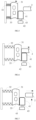
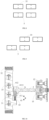
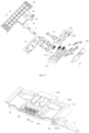
- FIG.1 is a structural schematic diagram of a hinge assembly 100 according to an illustrative embodiment.
- FIG.2 is an exploded schematic diagram of a driving rod 2, a magnetic assembly 3 and a limiting assembly 4 according to an illustrative embodiment.
- FIG.3 is a structural schematic diagram of a hinge body 1 according to an illustrative embodiment.
- the hinge assembly 100 may include a hinge body 1, a driving rod 2, a magnetic assembly 3 and a limiting assembly 4.
- the hinge body 1 may be used to couple to a housing of an electronic device equipped with the hinge assembly 100.
- the hinge body 1 may include the folded state and an unfolded state, and may be switched between the folded state and the unfolded state.
- the folded state is a state of being folded by 90 degrees relative to the unfolded state.
- the hinge body 1 may only hover in the unfolded state and the folded state.
- the hinge body 1 may also hover in any bending state between the unfolded state and the folded state, and the bending state may be a state of being bent by 30 degrees, 60 degrees or any other angle relative to the unfolded state, which is not limited by the present disclosure.
- a first end of the driving rod 2 may be slidably coupled to the hinge body 1, and a second end of the driving rod 2 may be slidably coupled to the magnetic assembly 3 along the first direction.
- the magnetic assembly 3 may be coupled to the housing of the electronic device equipped with the hinge assembly 100, that is, the magnetic assembly 3 and the hinge body 1 may be relatively fixed through the housing of the electronic device, and the driving rod 2 may inherently slide relative to the magnetic assembly 3 when sliding relative to the hinge body 1.
- the first end of the driving rod 2 may slide relative to the hinge body 1 along the first direction and the second end of the driving rod 2 may slide relative to the magnetic assembly 3 along the first direction.
- the first direction is the length direction of the driving rod 2, that is, a direction indicated by arrow A in FIGS. 1 and 2 .
- the first end of the driving rod 2 may slide relative to the hinge body 1 in the direction from the upper left to the lower right in FIG.2
- the second end of the driving rod 2 may slide relative to the magnetic assembly 3 in the direction from the upper left to the lower right in FIG.2 to move away from the magnetic assembly 3.
- the first end of the driving rod 2 may slide relative to the hinge body 1 in the direction from the lower right to the upper left in FIG.2 , and the second end of the driving rod 2 may slide relative to the magnetic assembly 3 in the direction from the lower right to the upper left in FIG.2 to move closer to the magnetic assembly 3.
- the first end of the driving rod 2 may slide relative to the hinge body 1 in the direction from the lower right to the upper left in FIG.2
- the second end of the driving rod 2 may slide relative to the magnetic assembly 3 in the direction from the lower right to the upper left in FIG.2 to move closer to the magnetic assembly 3.
- the first end of the driving rod 2 may slide relative to the hinge body 1 in the direction from the upper left to the lower right in FIG.2
- the second end of the driving rod 2 may slide relative to the magnetic assembly 3 in the direction from the upper left to the lower right in FIG.2 to move away from the magnetic assembly 3, which is not limited by the present disclosure.
- the sliding coupling between the driving rod 2 and the hinge body 1, and the sliding coupling between the driving rod 2 and the magnetic assembly 3 may all be realized by fitting of a chute with a guide rail.
- the limiting assembly 4 may include a locked state and an unlocked state.
- a part of the limiting assembly 4 may be located between two opposite surfaces of the driving rod 2 and the magnetic assembly 3.
- the limiting assembly 4 may move out of the two opposite surfaces of the driving rod 2 and the magnetic assembly 3.
- the hinge body 1 is switched to the folded state, the limiting assembly 4 may be in the locked state, and the driving rod 2 may press against the limiting assembly 4 and then press against the magnetic assembly 3, such that the magnetic assembly 3 may be maintained in the first position.
- the magnetic assembly 3 may move from the first position towards the driving rod 2 along the first direction to the second position.
- the magnetic assembly 3 may be pressed by the fitting of the limiting assembly 4 and the driving rod 2 may press against the magnetic assembly 3 to be kept in the first position, which is beneficial to maintaining the folded state of the hinge body 1 through the mutual attraction between the magnetic assembly 3 and the matching magnetic member, and subsequently the limiting assembly 4 may be switched to the unlocked state in response to the operation instruction, and the magnetic assembly 3 may be switched to the second position to release the interaction force of attraction.
- the flexible screen of the electronic device equipped with the hinge assembly 100 is also in the folded state when the hinge assembly 100 is in the folded state, the flexible screen may release the internal stress to restore to the flattened state without attractive force when the magnetic assembly 3 is switched to the second position, such that the hinge assembly 100 may be driven to restore to the unfolded state, and the automatic unfolding of the hinge assembly 100 and the electronic device may be realized, and the user does not need to manually unfold the folding electronic devices under the trend of lightweight and thinness, thus improving the user experience.
- the magnetic assembly 3 may include a magnet bracket 31 and a first elastic member 32.
- the magnet bracket 31 may be slidably coupled to the driving rod 2 along the first direction.
- An end of the first elastic member 32 may be coupled to the magnet bracket 31, and the other end may be configured for fixing, for example, to the housing of the electronic device equipped with the hinge assembly 100.
- FIGS.4-7 when the hinge body 1 is in the folded state, the first elastic member 32 is compressed, and when the limiting assembly 4 is switched to the unlocked state in response to an operation instruction, the limiting assembly 4 moves out from between the two opposite surfaces of the driving rod 2 and the magnet to provide a space gap for the first elastic member 32 to restore deformation, thereby providing a force to the magnet bracket 31 to move the magnet bracket 31.
- the whole magnetic assembly 3 may be switched from the first position to the second position, such that the magnetic assembly 3 and the matching magnetic member no longer attract each other, and the hinge assembly 100 may be automatically unfolded by using the internal force of the flexible screen of the electronic device.
- the first elastic member 32 may include a compression spring.
- the magnetic assembly 3 may include a first magnetic member 33, and the magnetic member 33 may be arranged on the magnet bracket 31.
- the hinge assembly 100 may include a second magnetic member 5.
- the first magnetic member 33 and the second magnetic member 5 attract each other in a second direction perpendicular to the first direction.
- the magnetic assembly 3 is in the second position, as illustrated in FIG.9 , the first magnetic member 33 and the second magnetic member 5 repel each other.
- the magnetic assembly 3 When the magnetic assembly 3 is in the second position, the mutual repulsion between the first magnetic member 33 and the second magnetic member 5 may generate a repulsive force perpendicular to the first direction, which may provide a force for the hinge assembly 100 to restore to the unfolded state.
- the force between the first magnetic member 33 and the second magnetic member 5 may be zero, and at this time, the hinge assembly 100 may be restored to the unfolded state by the internal force of the flexible screen of the electronic device equipped with the hinge assembly 100, and the electronic device may be unfolded automatically.
- the first magnetic assembly 3 may be located inside one side of the main body of the device equipped with the hinge assembly 100, and the second magnetic assembly 3 may be located in the other side of the main body of the device equipped with the hinge assembly 100.
- the limiting assembly 4 may include a limiting member 41 and a driving member 42.
- the driving member 42 may be fixed to the magnet bracket 31, and the limiting member 41 may be coupled to the driving member 42.
- the limiting member 41 may be driven to move in a second direction under the driving action of the driving member 42, that is, the limiting member 41 may move in a direction illustrated by the arrow B in FIG. 10 , and the second direction is perpendicular to the first direction (the direction illustrated by the arrow A). Based on this, when the hinge body 1 is in the folded state, at least a part of the limiting member 41 may be located between the two opposite surfaces of the driving rod 2 and the magnet bracket 31, and the limiting member component 4 is in the locked state.
- the driving member 42 may act on the limiting member 41 in response to the operation instruction, such that the limiting member 41 moves out of the two opposite surfaces of the driving rod 2 and the magnet bracket 31, and a gap is formed between the driving rod 2 and the magnet.
- the first elastic member 32 returns and pushes the magnet bracket 31, such that the magnetic assembly 3 moves from the first position towards the driving rod 2 along the first direction to the second position, and the mutual attractive force between the first magnetic member 33 and the second magnetic member 5 is released, such that the hinge body 1 may be automatically switched to the unfolded state, and the electronic device equipped with the hinge assembly 100 may be automatically unfolded.
- the driving member 42 may include an output shaft, and the output shaft and the limiting member 41 may be coupled in a threaded way, such that the limiting member 41 may be driven to reciprocate in the second direction through the rotation of the output shaft;
- the driving member 42 may include a memory metal, and the limiting member 41 is driven by the stretching and contraction of the memory metal with electricity.
- the driving member 42 may include an electromagnet.
- the limiting assembly 4 may further include a second elastic member 43, and the second elastic member 43 is arranged along the second direction. A first end of the second elastic member 43 is coupled to the magnet bracket 31, and a second end of the second elastic member 43 is coupled to the limiting member 41.
- the driving member 42 responds to the operation instruction, the limiting member 41 moves along the second direction and compresses the second elastic member 43, and the limiting assembly 4 is switched to the unlocked state.
- the driving rod 2 may limit the limiting member 41 in the second direction, and the second elastic member 43 remains in a compressed state.
- the second elastic member 43 may be return, the limiting member 41 returns under the action of the second elastic member 43, and the limiting assembly 4 is switched to the locked state, and the limiting member 41 may be located between the two opposite surfaces of the driving rod 2 and the magnet bracket 31.
- the magnet bracket 31 may include a body part 311, a first extension part 312 and a second extension part 313. Both of the first extension part 312 and the second extension part 313 are coupled to the body part 311, and both the first extension part 312 and the second extension part 313 are formed by extending outwards from an edge of the body part 311 parallel to the second direction, and an interval distance is defined between the first extension part and the second extension part 313 in the second direction.
- the first magnetic member 33 of the magnetic assembly 3 may be arranged in the body part 311, for example, the body part 311 may include an installation groove, one or a plurality of first magnetic members 33 may be arranged in the installation groove.
- the plurality of first magnetic members 33 may be arranged side by side or in multiple rows, and may be designed adaptively according to the shape of the installation groove, which is not limited by the present disclosure.
- the first extension part 312 may include a groove 3121 that is recessed along the first direction. An end of the driving rod 2 away from the hinge body 1 may extend into the groove 3121 to be slidably coupled to the magnet bracket 31.
- the driving member 42 of the limiting assembly 4 may be coupled to the second extension part 313.
- the limiting member 41 extends toward the first extension part 312 in the second direction and extends into the groove 3121, and the limiting member 41 may be slidably coupled to the first extension part 312, such that the movement of the limiting member 41 may be limited when the driving member 42 or the second elastic member 43 subsequently acts on the limiting member 41.
- the limiting member 41 may include a guide groove
- the first extension part 312 may include a guide block arranged in the groove 3121, and the limiting member 41 is limited by the sliding coupling between the guide block and the guide groove.
- the movement of the limiting member 41 may be limited by the fitting between the chute and the guide rail, which is not limited by the present disclosure.
- the shapes of the first extension part 312 and the second extension part 313 may be adaptively designed.
- All the above embodiments may be applied to the technical solution that when the hinge body 1 switches to the unfolded state, the driving rod 2 moves away from the magnetic assembly 3, and when the hinge body 1 switches to the folded state, the driving rod 2 moves closer to the magnetic assembly 3; and may also be applied to the technical solution that when the hinge body 1 switches to the unfolded state, the driving rod 2 moves closer to the magnetic assembly 3, and when the hinge body 1 switches to the folded state, the driving rod 2 moves away from the magnetic assembly 3.
- the automatic reset in the above two structures will be illustrated as follows.
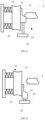
- the driving rod 2 moves away from the magnetic assembly 3 when the hinge body 1 is switched to the unfolded state, and the driving rod 2 moves closer to the magnetic assembly 3 when the hinge body 1 is switched to the folded state, as illustrated in FIG.4- FIG.7 , in the process of switching the folded state of the hinge body 1, the driving rod 2 may move closer to the magnetic assembly 3 from right to left. In the process of continuous folding, an end of the driving rod 2 may press against the magnet bracket 31 through the limiting assembly 4 to further compress the first elastic member 32. The magnetic assembly 3 is in the first position, and the first elastic member 32 is in the compressed state until the hinge body 1 is switched to the folded state where the relative position relationship of the magnetic assembly 3, the limiting assembly 4 and the driving rod 2 is illustrated in FIG.4 .
- the first magnetic member 33 and the second magnetic member 5 attract each other.
- the limiting assembly 4 may move out of the two opposite surfaces of the magnet bracket 31 and the driving rod 2, thus providing a space gap and the first elastic member 32 restores deformation and switches to the state illustrated in FIG.6 , the magnet bracket 31 moves in the direction from right to left in FIG.6 under the action of the first elastic member 32, and the magnetic assembly 3 switches to the second position.
- the first magnetic member 33 and the second magnetic member 33 repel each other, and under the action of the repulsive force and the flexible screen, the hinge body 1 switches to the unfolded state, and the electronic device automatically unfolds.
- the driving rod 2 may move away from the magnetic assembly 3, that is, the driving rod 2 may move in the direction from left to right in FIG.7 , and the limiting of the driving rod 2 on the limiting assembly 4 in the second direction may be released, and the second elastic member 43 may restore deformation, and under the action of the second elastic member 43, the limiting assembly 41 may move from bottom to top, and the limiting assembly 4 may be restored to the locked state, such that when the hinge assembly 100 is subsequently switched to the folded state, the driving rod 2 presses against the magnetic assembly 3 by pressing against limiting assembly 4.
- the above-mentioned directions from top to bottom and from left to right are all illustrated in the corresponding legend, and the moving direction in the actual spatial structure may be determined
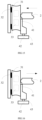
- the driving rod 2 moves closer to the magnetic assembly 3 when the hinge body 1 is switched to the unfolded state, and the driving rod 2 moves away from the magnetic assembly 3 when the hinge body 1 is switched to the folded state, as illustrated in FIGS.11-18 , when the hinge body 1 is in the folded state, the relative positional relationship of the driving rod 2, the limiting assembly 4 and the magnetic assembly 3 is illustrated in FIG. 11 , and at this time, the limiting assembly 4 is in the locked state, the driving rod 2 presses against the magnet bracket 31 by pressing against the limiting member 41, and the first elastic member 32 is compressed. At this time, as illustrated in FIG.8 , the first magnetic member 33 and the second magnetic member 5 attract each other.
- the limiting member 41 moves out of the two opposite surfaces of the driving rod 2 and the magnet bracket 31, such that a space gap may be provided and under the action of the first elastic member 32, the magnet bracket 31 may be pushed to slide in the direction from left to right in FIG.2 and be switched to the state illustrated in FIG. 13 , and the magnetic assembly 13 is switched to the second position.
- the first magnetic member 33 and the second magnetic member 5 repel each other, and under the action of the repulsive force and the flexible screen, the hinge body 1 switches to the unfolded state, and the electronic device automatically unfolds.
- the driving rod 2 may move closer to the magnet bracket 31, that is, the driving rod 2 may move in the direction from right to left as illustrated in FIG.14 , and the driving rod 2 may continuously press against the first elastic member 32, and may continuously limit the limiting member 41 in the second direction, such that the second elastic member 43 is continuously compressed.
- the hinge body 1 since the hinge body 1 has unfolded at a certain angle at this time, the first magnetic member 33 and the second magnetic member 5 cannot attract each other, so the hinge body 1 may be automatically switched to the unfolded state all the time.
- the relative positional relationship of the magnetic assembly 3, limiting assembly 4 and the driving rod 2 is illustrated in FIG. 15 .
- the driving rod 2 may move away from the magnet bracket 31 from left to right as illustrated in FIG.16 , and the first elastic member 32 gradually returns, until the first elastic member 32 is in a natural state and there is a certain gap between the driving rod 2 and the magnet bracket 31 as illustrated in FIG.17 .
- the second elastic member 43 may restore deformation and push the limiting member 41 to move from bottom to top in FIG.17 , the limiting assembly 4 is switched to the locked state, and the first elastic member 32 may be compressed due to the extension of the limiting member 41 as illustrated in FIG.18 .
- the driving rod 2 moves from right to left in FIG.18 , and the first elastic member 32 restores deformation.
- the magnet bracket 31 and the limiting assembly 4 both move from right to left until switching to the relative positional relationship illustrated in FIG.11 .
- the hinge body 1 switches to the folded state.
- the limiting member 41 may include a tip end 412 and a tail part 411 coupled to the tip end 412. It may be understood that in the first direction, a width of the tail part 411 may be greater than a width of the tip end 412, and the tail part 411 may be coupled to the second elastic member 43.
- the tip end 412 may be pushed into between the driving rod 2 and the magnet bracket 31 under the action of the second elastic member 43, and the tail part 411 may be further extended into between the driving rod 2 and the magnet bracket 31 to compress the first elastic member 32.
- the tail part 411 may include a first guide surface 4111 inclined in the direction pointing form the tip end 412 to the tail part 411, and the end of the driving rod 2 away from the hinge body 1 may include a second guide surface 21. Through the fitting of the first guide surface 4111 and the second guide surface 21, the smoothness of the tail part 411 extending into between the magnet bracket 31 and the driving rod 2 may be improved, and the compression of the first elastic member 32 may be realized.
- the hinge body 1 may include a seat 11, a first support member 12 and a second support member 13.
- the first support member 12 is coupled to a first side of the seat 11, and the second support member 13 is coupled to a second side of the seat 11.
- the driving rod 2 may be slidably coupled to the first support member 12.
- the first support member 12 and the second support member 13 separately rotate relative to the seat 11 and move in the direction closer to the seat 11.
- the first end of the driving rod 2 fitted with the first support member 12 may slide relative to the first support member 12, and the second end of the driving rod 2 may slide relative to the magnet bracket 31 and the driving rod 2 moves closer to the magnet bracket 31 to release the limiting on the limiting assembly 4.
- the hinge body 1 may further include a plurality of control pull-rods 14. At least one control pull-rod 14 has a first end movably coupled to the seat 11 and a second end rotatably coupled to the first support member 12, and at least one control pull-rod 14 has a first end movably coupled to the seat 11 and a second end rotatably coupled to the second support member 13.
- the first support member 12 may be driven to rotate relative to the seat 11, and the first support member 12 may be moved closer to or away from the seat 11.
- the hinge body 1 includes four control pull-rods 14, which are symmetrically arranged in pairs; In other embodiments, the hinge body 1 may also include two or three control pull-rods 14 or other numbers of control pull-rods 14, which is not limited by the present disclosure.
- the seat 11 may include an arc-shaped track
- each control pull-rod 14 may include an arc-shaped guide part 141 and a rotating part 142 coupled to the arc-shaped guide part 141.
- the rotating part 142 is configured to rotatably coupling to the first support member 12 or the second support member 13, and the arc-shaped guide part 141 may be fitted with the arc-shaped track of the seat 11.
- the rotating part 142 may be pushed to move along the length direction of the control pull-rod 14, such that the rotating part 142 of the control pull-rod 14 coupled to the first support member 12 may drive the first support member 12 to move closer to or away from the seat 11 while driving the first support member 12 to rotate relative to the seat 11, and the rotating part 142 of the control pull-rod 14 coupled to the second support member 13 may drive the second support member 13 move closer to or away from the seat 11 while driving the second support member 13 to rotate relative to the seat 11.
- the seat 11 may include a bracket 111 and a cover 112 coupled to the bracket 111.
- the bracket 111 may include an arc-shaped recessed part 1111
- the cover 112 may include an arc-shaped protruded part 1121.
- the arc-shaped protruded part 1121 may extend into the arc-shaped recessed part 1111 to form the arc-shaped track when the cover 112 is assembled with the bracket 111.
- the arc-shaped track may be formed by assembling the bracket 111 and the cover 112, facilitating the installation of the control pull-rod 14.
- the arc-shaped recessed part 1111 may have a semicircle shape
- the arc-shaped protruded part 1121 may have a semicircle shape
- a radius of the arc-shaped protruded part 1121 is smaller than a radius of the arc-shaped recessed part 1111, such that when the arc-shaped protruded part 1121 is fitted with the arc-shaped recessed part 1111, the arc-shaped track may be formed due to the radius difference.
- the arc-shaped guide part 141 may have a semicircle shape to fit with the arc-shaped track.
- the arc-shaped protruded part 1121 and the arc-shaped recessed part 1111 having the semicircle shape are described herein as an example only, and in other embodiments, they may also have other shapes, as long as a displacement change may occur while a movable part rotates relative to the arc-shaped track.
- the hinge body 1 may further include a synchronization mechanism 15.
- the synchronization mechanism 15 may include a first guide rod gear 151 and a second guide rod gear 152.
- the first guide rod gear 151 includes a first guide rod end 1511 and a first gear end 1512
- the second guide rod gear 152 includes a second guide rod end 1521 and a second gear end 1522.
- the first gear end 1512 and the second gear end 1522 are directly or indirectly meshed, and the first gear end 1512 and the second gear end 1522 are rotatably coupled to the seat 11.
- the first guide rod end 1511 is slidably coupled to the first support member 12, and the second guide rod end 1521 is slidably coupled to the second support member 13.
- the control pull-rod 14 may be driven to rotate relative to the seat 11, such that the first support member 12 moves away from or closer to the seat 11.
- the first gear end 1512 of the first guide rod gear 151 rotates synchronously, such that the second gear end 1522 of the second guide rod gear 152 is driven to rotate synchronously, to realize that the hinge body 1 is folded in half.
- the driving rod 2 may be directly rotatably coupled to the seat 11, and simultaneously slidably coupled to the first support member 12 and the magnet bracket 31 in the first direction, such that when the first support member 12 rotates relative to the seat 11 and moves away from or closer to the seat 11, the driving rod 2 may also rotate relative to the seat 11 and move closer to or away from the magnet bracket 31 along the first direction.
- the driving rod 2 may include a mating slot 22, and the first guide rod end 1511 of the first guide rod gear 151 may include a column 15111. The column 15111 may extend into the mating slot 22.
- the driving rod 2 may be synchronously driven to rotate relative to the seat 11 through the column 15111, and at the same time, the driving rod 2 may slide in the first direction relative to the first support member 12 and the magnet bracket 31.
- the present disclosure is beneficial to shortening the length of the driving rod 2 and improving the strength of the driving rod 2.
- the synchronization mechanism 15 may further include a gear set 153.
- the gear set 153 may include an even number of gears, and the gear set 153 may have a first end gear meshing with the first gear end 1512 and a second end gear meshing with the second gear end 1522.
- the gear set 153 includes two gears meshed with each other, with a left gear meshing with the second gear end 1522, and a right gear meshing with the first gear end 1512, to realize power transmission.
- both the first gear end 1512 and the second gear end 1522 may be ensured to rotate towards the same side of the seat 11.
- the hinge body 1 may include a seat 11, a first support member 12 and a second support member 13.
- the first support member 12 is coupled to a first side of the seat 11, and the second support member 13 is coupled to a second side of the seat 11.
- the driving rod 2 may be slidably coupled to the first support member 12.
- the first support member 12 and the second support member 13 may rotate relative to the seat 11 and move in the direction away from the seat 11, the first end of the driving rod 2 fitted with the first support member 12 may slide relative to the first support member 12, the second end of the driving rod 2 may slide relative to the magnet bracket 31, and the driving rod 2 moves closer to the magnet bracket 31.
- the first support member 12 and the second support member 13 separately rotate relative to the seat 11 and move in the direction closer to the seat 11.
- the first end of the driving rod 2 fitted with the first support member 12 may slide relative to the first support member 12, the second end of the driving rod 2 may slide relative to the magnet bracket 31, and the driving rod 2 moves away from the magnet bracket 31, to release the limiting on the limiting assembly 4.
- the slidable coupling between the first guide rod end 1511 and the first support member 12, the slidable coupling between the second guide rod end 1521 and the second support member 13, the slidable coupling between the driving rod 2 and the first support member 12, and the slidable coupling between the driving rod 2 and the magnet bracket 31 may all be realized by the way that the chute and the guide rail are fitted.
- the chute may be an open chute or a through chute, and the guide rail may be designed adaptively according to the structure and form of the chute, which is not limited by the present disclosure.
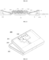
- the present disclosure also provides an electronic device 200.
- the electronic device 200 may include a first housing 201, a second housing 202, a flexible display panel 203 and a hinge assembly 100 described in any of the above embodiments, and the flexible display panel 203 may be arranged on the first housing 201 and the second housing 202.
- the hinge body 1 of the hinge assembly 100 may be coupled to the first housing 201 and the second housing 202, for example, the first housing 201 may be coupled to the first support member 12, and the second housing 202 may be coupled to the second support member 13.
- Both the magnetic assembly 3 and the limiting assembly 4 of the hinge assembly 100 may be arranged in the first housing 201, the first elastic member 32 of the magnetic assembly 3 may be fixedly coupled to the first housing, and the magnet bracket 31 may be slidably coupled to the first housing.
- the hinge body 1 When the hinge body 1 is in the folded state, the first housing and the second housing are oppositely arranged, the flexible display panel is folded in half, and the first magnetic member 33 of the magnetic assembly 3 may attract the second magnetic member 5 arranged in the second housing.
- the magnetic assembly 3 moves from the first position to the second position along the first direction towards the driving rod 2, the second magnetic member 5 of the magnetic assembly 3 is released from attraction, and the flexible display panel is unfolded under the action of internal force, thereby pushing the hinge body 1 to automatically switch to the unfolded state, and the electronic device is automatically unfolded, thus solving the disadvantages of the electronic device when the user unfold it with one hand under the trend of thin and lightweight electronic device.
Landscapes
- Engineering & Computer Science (AREA)
- General Engineering & Computer Science (AREA)
- Theoretical Computer Science (AREA)
- Computer Hardware Design (AREA)
- Physics & Mathematics (AREA)
- Signal Processing (AREA)
- Human Computer Interaction (AREA)
- General Physics & Mathematics (AREA)
- Mechanical Engineering (AREA)
- Mathematical Physics (AREA)
- Pivots And Pivotal Connections (AREA)
- Microelectronics & Electronic Packaging (AREA)
- Telephone Set Structure (AREA)
Abstract
Description
- The present application is based on and claims the priority of
Chinese patent application No.202110926282.8 filed on August 12, 2021 - The present disclosure relates to the field of terminals, and in particular to a hinge assembly and an electronic device.
- With the development of flexible OLED (Organic Light Emitting Diode) display technologies and the folding electronic devices having both the portability of ordinary electronic devices and the ultimate experience of large-screen display after being unfolded, the folding electronic devices have gradually become an important trend in the development of mobile terminals and an important field of competition among major terminal manufacturers.
- However, in the related art, the state switching of the folding electronic devices mainly depends on hinge assemblies, which drive the electronic device to fold and unfold through the folding and unfolding of the hinge assemblies.
- The present disclosure provides a hinge assembly and an electronic device.
- According to a first aspect of embodiments of the present disclosure, there is provided a hinge assembly, including:
- a hinge body including a folded state and an unfolded state;
- a driving rod, a first end of the driving rod being slidably coupled to the hinge body, when the hinge body is switched to the folded state or the unfolded state, the driving rod sliding relative to the hinge body in a first direction, the first direction being a length direction of the driving rod;
- a magnetic assembly slidably coupled to a second end of the driving rod along the first direction;
- a limiting assembly including a locked state and an unlocked state, a part of the limiting assembly being located between two opposite surfaces of the driving rod and the magnetic assembly when the limiting assembly is in the locked state, and the limiting assembly being located outside the two opposite surfaces of the driving rod and the magnetic assembly when the limiting assembly is in the unlocked state,
- when the hinge body is in the folded state, the driving rod presses against the magnetic assembly through the limiting assembly along the first direction such that the magnetic assembly is maintained in a first position; and in response to an operation instruction, the limiting assembly is switched to the unlocked state and the magnetic assembly moves from the first position towards the driving rod along the first direction to a second position.
- In some embodiments, the magnetic assembly includes:
- a magnet bracket slidably coupled to the driving rod along the first direction; and
- a first elastic member having a first end configured for fixing and a second end coupled to the magnet bracket,
- when the hinge body is in the folded state, the first elastic member is compressed, and when the limiting assembly is switched to the unlocked state in response to an operation instruction, the first elastic member returns to push the magnetic assembly to move from the first position towards the driving rod along the first direction to the second position.
- In some embodiments, the magnetic assembly includes a first magnetic member arranged on the magnet bracket; and the hinge assembly further includes a second magnetic member;
- when the magnetic assembly is in the first position, the first magnetic member and the second magnetic member attract each other along a second direction perpendicular to the first direction; and
- when the magnetic assembly is in the second position, an interaction force between the first magnetic member and the second magnetic member is zero.
- In some embodiments, the limiting assembly includes:
- a limiting member; and
- a driving member fixed on the magnet bracket, and configured to drive the limiting member to move along a second direction perpendicular to the first direction,
- when the hinge body is in the folded state, the limiting member is located between the two opposite surfaces of the driving rod and the magnet bracket, the driving rod presses against the magnet bracket through the limiting member along the first direction, and the first elastic member is compressed; and
- the driving member responds to an operation instruction, the limiting assembly is switched to the unlocked state, the limiting assembly moves out of the two opposite surfaces of the driving rod and the magnetic assembly, a gap is formed between the driving rod and the magnet, the first elastic member returns to push the magnet bracket, and the magnetic assembly moves from the first position towards the driving rod along the first direction to the second position.
- In some embodiments, the magnetic assembly further includes a second elastic member arranged along the second direction, and having a first end coupled to the magnet bracket and a second end coupled to the limiting member,
when the driving member responds to an operation instruction, the limiting member moves in the second direction and compresses the second elastic member, the limiting assembly is switched to the unlocked state, the limiting member, the second elastic member and the driving member move with the magnet bracket, and the driving rod limits the limiting member in the second direction; and when the driving rod slides away from the magnet bracket in the first direction to release limiting on the limiting member, the second elastic member returns, the limiting member returns, and the limiting assembly is switched to the locked state. - In some embodiments, the magnet bracket includes a body part, a first extension part and a second extension part, the first extension part and the second extension part extend from an edge of the body part parallel to the second direction; and
the first magnetic member is arranged on the body part, the first extension part includes a groove recessed along the first direction, an end of the driving rod away from the hinge body extends into the groove and is slidably coupled to the magnet bracket, the driving member is coupled to the second extension part, and the limiting member extends into the groove along the second direction and is slidably coupled to the first extension part. - In some embodiments, the hinge body includes a seat, a first support member and a second support member, the first support member and the second support member are respectively coupled to two sides of the seat, and the driving rod is slidably coupled to the first support member along the first direction; and
when the hinge body is switched to the folded state, the first support member and the second support member separately rotate relative to the seat and move away from the seat, and the driving rod slides along the first direction relative to the first support member and moves closer to the magnet bracket to press against the limiting member; when the hinge body is switched to the unfolded state, the first support member and the second support member separately rotate relative to the seat and move closer to the seat, the driving rod slides along the first direction relative to the first support member and moves away from the bracket, the second elastic member returns, and the limiting assembly is switched to the locked state. - In some embodiments, the hinge body includes a seat, a first support member and a second support member, the first support member and the second support member are respectively coupled to two sides of the seat, and the driving rod is slidably coupled to the first support member along the first direction;
- when the hinge body is in the folded state, the driving rod presses against the limiting member and the magnet bracket, the first elastic member is compressed, and when the driving member responds to an operation instruction, the limiting assembly is switched to the unlocked state, the first elastic member returns, the hinge body is switched to the unfolded state, the first support member and the second support member separately rotate relative to the seat and move closer to the seat, the driving rod slides along the first direction relative to the first support member and move closer to the magnet bracket, and the first elastic member is compressed; and
- when the hinge body is switched from the unfolded state to the folded state, the first support member and the second support member separately rotate relative to the seat and move away from the seat, the driving rod slides relative to the first support member along the first direction and moves away from the magnet bracket, the first elastic member returns until the driving rod releases the limiting on the limiting member, the second elastic member returns, and the limiting is switched to the locked state.
- In some embodiments, the limiting member includes a tail part and a tip end coupled to the tail part, and the tail part is coupled to the second elastic member
- In some embodiments, the tail part includes a first guide surface inclined along a direction pointing from the tip end to the tail part, and the driving rod includes a second guide surface located at the end far away from the hinge body, and the second guide surface is configured to fit with the first guide surface.
- In some embodiments, the hinge body includes a plurality of control pull-rods, at least one control pull-rod having a first end movably coupled to the seat and a second end rotatably coupled to the first support member, and at least one control pull-rod has a first end movably coupled to the seat and a second end rotatably coupled to the second support member;
any one of the control pull-rods is configured to drive the first support member or the second support member to rotate relative to the seat, and allow the first support member or the second support member to move away from or closer to the seat when rotating. - In some embodiments, the seat includes an arc-shaped track;
each control pull-rod includes an arc-shaped guide part and a rotating part coupled to the arc-shaped guide part, the rotating part is rotatably coupled to the first support member or the second support member, and the arc-shaped guide part is fitted with the arc-shaped track to drive the first support member or the second support member to rotate relative to the seat, and push the first support member or the second support member to move away from or closer to the seat when the arc-shaped guide part moves along the arc-shaped track. - In some embodiments, the seat includes a bracket and a cover, the bracket includes an arc-shaped recessed part and the cover includes an arc-shaped protruded part, and the arc-shaped protruded part is arranged in the arc-shaped recessed part to cooperatively form the arc-shaped track.
- In some embodiments, the hinge body further includes:
a synchronization mechanism including a first guide rod gear and a second guide rod gear, the first guide rod gear includes a first guide rod end and a first gear end, the second guide rod gear includes a second guide rod end and a second gear end, the second gear end is meshed with the first gear end, and the first gear end and the second gear end are rotatably coupled to the seat; the first guide rod end is slidably coupled to the first support member, and the second guide rod end is slidably coupled to the second support member. - In some embodiments, the driving rod includes a mating slot, and the first guide rod end includes a column, and the column extends into the mating slot to drive the driving rod to rotate relative to the seat and move relative to the first support member along the first direction when the first guide rod gear rotates.
- In some embodiments, the synchronization mechanism further includes a gear set including an even number of gears meshed with each other, and the gear set has a first end gear meshed with the first gear end and a second end gear meshed with the second gear end.
- In some embodiments, the first end of the driving rod is rotatably coupled to the seat, the second end of the driving rod faces the magnet bracket, and the driving rod is slidably coupled to the first support member and the magnet bracket along the first direction.
- According to a second aspect of embodiments of the present disclosure, there is provided an electronic device, including:
- a first housing;
- a second housing;
- a flexible display panel arranged on the first housing and the second housing;
- a hinge assembly according to any of the first aspect described above, the hinge body is coupled to the first housing and the second housing, and the magnetic assembly and the limiting assembly are both arranged in the first housing;
- when the hinge body is in the folded state, the first housing and the second housing are oppositely arranged, the flexible display panel is folded in half, and the magnetic assembly and the second magnetic member arranged in the second housing attract each other; and
- the limiting assembly is switched to the unlocked state in response to an operation instruction, the magnetic assembly moves from the first position towards the driving rod along the first direction to the second position, the magnetic assembly and the second magnetic member are released from attraction, and the flexible display panel is unfolded.
- The technical solution provided by embodiments of the present disclosure may include the following beneficial effects.
- It may be seen from the above-mentioned embodiments that in the technical solution of the present disclosure, the magnetic assembly may be pressed by the fitting of the limiting assembly and the driving rod to be kept in the first position, which is beneficial to maintaining the folded state of the hinge body through the mutual attraction between the magnetic assembly and the matching magnetic member; and subsequently the limiting assembly may be switched to the unlocked state in response to the operation instruction, and the magnetic assembly may be switched to the second position to release the interaction force of attraction. Subsequently, the hinge assembly may be driven to restore to the unfolded state under the action of the flexible screen of the electronic device equipped with the hinge assembly, such that the automatic unfolding of the hinge assembly and the electronic device may be realized, and the user does not need to manually unfold the folding electronic devices under the trend of lightweight and thinness, thus improving the user experience.
- It is to be understood that both the foregoing general description and the following detailed description are illustrative and explanatory only and are not restrictive of the present disclosure.
- The accompanying drawings, which are incorporated in and constitute a part of this specification, illustrate embodiments consistent with the present disclosure and together with the description, serve to explain the principles of the present disclosure.
-
FIG.1 is a schematic structural diagram of a hinge assembly according to an illustrative embodiment. -
FIG.2 is an exploded schematic diagram of a driving rod, a magnetic assembly and a limiting assembly according to an illustrative embodiment. -
FIG.3 is a schematic structural diagram of a hinge body according to an illustrative embodiment. -
FIG.4 is a first the schematic diagram of a motion state of a hinge assembly according to an illustrative embodiment. -
FIG.5 is a second schematic diagram of a motion state of a hinge assembly according to an illustrative embodiment. -
FIG.6 is a third schematic diagram of a motion state of a hinge assembly according to an illustrative embodiment. -
FIG.7 is a fourth schematic diagram of a motion state of a hinge assembly according to an illustrative embodiment. -
FIG.8 is a schematic diagram showing a positional relationship between a first magnetic member and a second magnetic member according to an illustrative embodiment. -
FIG.9 is a schematic diagram showing another positional relationship between a first magnetic member and a second magnetic member according to an illustrative embodiment. -
FIG. 10 is a partial sectional schematic diagram of a hinge assembly according to an illustrative embodiment. -
FIG.11 is a first schematic diagram of a motion state of another hinge assembly according to an illustrative embodiment. -
FIG.12 is a second schematic diagram of a motion state of another hinge assembly according to an illustrative embodiment. -
FIG.13 is a third schematic diagram of a motion state of another hinge assembly according to an illustrative embodiment. -
FIG.14 is a fourth schematic diagram of a motion state of another hinge assembly according to an illustrative embodiment. -
FIG.15 is a fifth schematic diagram of a motion state of another hinge assembly according to an illustrative embodiment. -
FIG.16 is a sixth schematic diagram of a motion state of another hinge assembly according to an illustrative embodiment. -
FIG.17 is a seventh schematic diagram of a motion state of another hinge assembly according to an illustrative embodiment. -
FIG.18 is an eighth schematic diagram of a motion state of another hinge assembly according to an illustrative embodiment. -
FIG.19 is an exploded schematic diagram of a hinge assembly according to an illustrative embodiment. -
FIG.20 is a three-dimensional sectional schematic diagram of a hinge assembly according to an illustrative embodiment. -
FIG.21 is a two-dimensional sectional schematic diagram of a hinge assembly according to an illustrative embodiment. -
FIG.22 is a schematic structural diagram of an electronic device according to an illustrative embodiment. -
FIG.23 is a schematic sectional diagram of an electronic device according to an illustrative embodiment. - Reference will now be made in detail to illustrative embodiments, examples of which are illustrated in the accompanying drawings. When the following description refers to the drawings, unless otherwise indicated, the same numbers in different drawings indicate the same or similar elements. The implementations described in the following illustrative embodiments do not represent all implementations consistent with the present disclosure. Rather, they are merely examples of devices and methods consistent with some aspects of the present disclosure as detailed in the appended claims.
- The terminology used in the present disclosure is for the purpose of describing specific embodiments only and is not intended to limit the present disclosure. The singular forms of expressions "a", "said" and "the" used in the present disclosure and the appended claims are also intended to include the plural forms, unless the context clearly indicates other meaning. It should also be understood that the term "and/or" as used herein refers to and includes any or all possible combinations of one or more associated listed items.
- It should be understood that although the terms first, second, third, etc. may be used to describe various information in the present disclosure, these information should not be limited to these terms. These terms are only used to distinguish the same type of information from each other. For example, without departing from the scope of the present disclosure, the first information may also be called the second information, and similarly, the second information may also be called the first information. Depending on the context, the word "if" as used herein may be interpreted as "at the time of" or "when" or "in response to determining that".
-
FIG.1 is a structural schematic diagram of ahinge assembly 100 according to an illustrative embodiment.FIG.2 is an exploded schematic diagram of a drivingrod 2, amagnetic assembly 3 and a limiting assembly 4 according to an illustrative embodiment.FIG.3 is a structural schematic diagram of ahinge body 1 according to an illustrative embodiment. As illustrated inFIGS. 1 to 3 , thehinge assembly 100 may include ahinge body 1, a drivingrod 2, amagnetic assembly 3 and a limiting assembly 4. Thehinge body 1 may be used to couple to a housing of an electronic device equipped with thehinge assembly 100. Thehinge body 1 may include the folded state and an unfolded state, and may be switched between the folded state and the unfolded state. The folded state is a state of being folded by 90 degrees relative to the unfolded state. In some embodiments, thehinge body 1 may only hover in the unfolded state and the folded state. In other embodiments, thehinge body 1 may also hover in any bending state between the unfolded state and the folded state, and the bending state may be a state of being bent by 30 degrees, 60 degrees or any other angle relative to the unfolded state, which is not limited by the present disclosure. - A first end of the driving
rod 2 may be slidably coupled to thehinge body 1, and a second end of the drivingrod 2 may be slidably coupled to themagnetic assembly 3 along the first direction. Themagnetic assembly 3 may be coupled to the housing of the electronic device equipped with thehinge assembly 100, that is, themagnetic assembly 3 and thehinge body 1 may be relatively fixed through the housing of the electronic device, and the drivingrod 2 may inherently slide relative to themagnetic assembly 3 when sliding relative to thehinge body 1. When thehinge body 1 is switched to the unfolded state or the folded state, the first end of the drivingrod 2 may slide relative to thehinge body 1 along the first direction and the second end of the drivingrod 2 may slide relative to themagnetic assembly 3 along the first direction. The first direction is the length direction of the drivingrod 2, that is, a direction indicated by arrow A inFIGS. 1 and 2 . For example, in some embodiments, when thehinge body 1 is switched to the unfolded state, the first end of the drivingrod 2 may slide relative to thehinge body 1 in the direction from the upper left to the lower right inFIG.2 , and the second end of the drivingrod 2 may slide relative to themagnetic assembly 3 in the direction from the upper left to the lower right inFIG.2 to move away from themagnetic assembly 3. When thehinge body 1 is switched to the folded state, the first end of the drivingrod 2 may slide relative to thehinge body 1 in the direction from the lower right to the upper left inFIG.2 , and the second end of the drivingrod 2 may slide relative to themagnetic assembly 3 in the direction from the lower right to the upper left inFIG.2 to move closer to themagnetic assembly 3. In other embodiments, when thehinge body 1 is switched to the unfolded state, the first end of the drivingrod 2 may slide relative to thehinge body 1 in the direction from the lower right to the upper left inFIG.2 , and the second end of the drivingrod 2 may slide relative to themagnetic assembly 3 in the direction from the lower right to the upper left inFIG.2 to move closer to themagnetic assembly 3. When thehinge body 1 is switched to the folded state, the first end of the drivingrod 2 may slide relative to thehinge body 1 in the direction from the upper left to the lower right inFIG.2 , and the second end of the drivingrod 2 may slide relative to themagnetic assembly 3 in the direction from the upper left to the lower right inFIG.2 to move away from themagnetic assembly 3, which is not limited by the present disclosure. The sliding coupling between the drivingrod 2 and thehinge body 1, and the sliding coupling between the drivingrod 2 and themagnetic assembly 3 may all be realized by fitting of a chute with a guide rail. - The limiting assembly 4 may include a locked state and an unlocked state. When the limiting assembly 4 is in the locked state, a part of the limiting assembly 4 may be located between two opposite surfaces of the driving
rod 2 and themagnetic assembly 3. When the limiting assembly 4 is in the unlocked state, the limiting assembly 4 may move out of the two opposite surfaces of the drivingrod 2 and themagnetic assembly 3. When thehinge body 1 is switched to the folded state, the limiting assembly 4 may be in the locked state, and the drivingrod 2 may press against the limiting assembly 4 and then press against themagnetic assembly 3, such that themagnetic assembly 3 may be maintained in the first position. When the limiting assembly 4 is switched to the unlocked state in response to an operation instruction, themagnetic assembly 3 may move from the first position towards the drivingrod 2 along the first direction to the second position. - Based on this, the
magnetic assembly 3 may be pressed by the fitting of the limiting assembly 4 and the drivingrod 2 may press against themagnetic assembly 3 to be kept in the first position, which is beneficial to maintaining the folded state of thehinge body 1 through the mutual attraction between themagnetic assembly 3 and the matching magnetic member, and subsequently the limiting assembly 4 may be switched to the unlocked state in response to the operation instruction, and themagnetic assembly 3 may be switched to the second position to release the interaction force of attraction. Because the flexible screen of the electronic device equipped with thehinge assembly 100 is also in the folded state when thehinge assembly 100 is in the folded state, the flexible screen may release the internal stress to restore to the flattened state without attractive force when themagnetic assembly 3 is switched to the second position, such that thehinge assembly 100 may be driven to restore to the unfolded state, and the automatic unfolding of thehinge assembly 100 and the electronic device may be realized, and the user does not need to manually unfold the folding electronic devices under the trend of lightweight and thinness, thus improving the user experience. - The
magnetic assembly 3 may include amagnet bracket 31 and a firstelastic member 32. Themagnet bracket 31 may be slidably coupled to the drivingrod 2 along the first direction. An end of the firstelastic member 32 may be coupled to themagnet bracket 31, and the other end may be configured for fixing, for example, to the housing of the electronic device equipped with thehinge assembly 100. As illustrated inFIGS.4-7 , when thehinge body 1 is in the folded state, the firstelastic member 32 is compressed, and when the limiting assembly 4 is switched to the unlocked state in response to an operation instruction, the limiting assembly 4 moves out from between the two opposite surfaces of the drivingrod 2 and the magnet to provide a space gap for the firstelastic member 32 to restore deformation, thereby providing a force to themagnet bracket 31 to move themagnet bracket 31. Therefore, the wholemagnetic assembly 3 may be switched from the first position to the second position, such that themagnetic assembly 3 and the matching magnetic member no longer attract each other, and thehinge assembly 100 may be automatically unfolded by using the internal force of the flexible screen of the electronic device. The firstelastic member 32 may include a compression spring. - Still as illustrated in
FIGS. 4-7 , themagnetic assembly 3 may include a firstmagnetic member 33, and themagnetic member 33 may be arranged on themagnet bracket 31. Thehinge assembly 100 may include a secondmagnetic member 5. When themagnetic assembly 3 is in the first position, as illustrated inFIG.8 , the firstmagnetic member 33 and the secondmagnetic member 5 attract each other in a second direction perpendicular to the first direction. When themagnetic assembly 3 is in the second position, as illustrated inFIG.9 , the firstmagnetic member 33 and the secondmagnetic member 5 repel each other. When themagnetic assembly 3 is in the second position, the mutual repulsion between the firstmagnetic member 33 and the secondmagnetic member 5 may generate a repulsive force perpendicular to the first direction, which may provide a force for thehinge assembly 100 to restore to the unfolded state. In some embodiments, when themagnetic assembly 3 is in the second position, the force between the firstmagnetic member 33 and the secondmagnetic member 5 may be zero, and at this time, thehinge assembly 100 may be restored to the unfolded state by the internal force of the flexible screen of the electronic device equipped with thehinge assembly 100, and the electronic device may be unfolded automatically. The firstmagnetic assembly 3 may be located inside one side of the main body of the device equipped with thehinge assembly 100, and the secondmagnetic assembly 3 may be located in the other side of the main body of the device equipped with thehinge assembly 100. - As illustrated in
FIG. 10 , the limiting assembly 4 may include a limitingmember 41 and a drivingmember 42. The drivingmember 42 may be fixed to themagnet bracket 31, and the limitingmember 41 may be coupled to the drivingmember 42. The limitingmember 41 may be driven to move in a second direction under the driving action of the drivingmember 42, that is, the limitingmember 41 may move in a direction illustrated by the arrow B inFIG. 10 , and the second direction is perpendicular to the first direction (the direction illustrated by the arrow A). Based on this, when thehinge body 1 is in the folded state, at least a part of the limitingmember 41 may be located between the two opposite surfaces of the drivingrod 2 and themagnet bracket 31, and the limiting member component 4 is in the locked state. The drivingmember 42 may act on the limitingmember 41 in response to the operation instruction, such that the limitingmember 41 moves out of the two opposite surfaces of the drivingrod 2 and themagnet bracket 31, and a gap is formed between the drivingrod 2 and the magnet. The firstelastic member 32 returns and pushes themagnet bracket 31, such that themagnetic assembly 3 moves from the first position towards the drivingrod 2 along the first direction to the second position, and the mutual attractive force between the firstmagnetic member 33 and the secondmagnetic member 5 is released, such that thehinge body 1 may be automatically switched to the unfolded state, and the electronic device equipped with thehinge assembly 100 may be automatically unfolded. - The driving
member 42 may include an output shaft, and the output shaft and the limitingmember 41 may be coupled in a threaded way, such that the limitingmember 41 may be driven to reciprocate in the second direction through the rotation of the output shaft; In another embodiment, the drivingmember 42 may include a memory metal, and the limitingmember 41 is driven by the stretching and contraction of the memory metal with electricity. In some embodiments, the drivingmember 42 may include an electromagnet. - The limiting assembly 4 may further include a second
elastic member 43, and the secondelastic member 43 is arranged along the second direction. A first end of the secondelastic member 43 is coupled to themagnet bracket 31, and a second end of the secondelastic member 43 is coupled to the limitingmember 41. When the drivingmember 42 responds to the operation instruction, the limitingmember 41 moves along the second direction and compresses the secondelastic member 43, and the limiting assembly 4 is switched to the unlocked state. At the same time, under the action of the firstelastic member 32, the limitingmember 41, the secondelastic member 43 and the drivingmember 42 move with themagnet bracket 31, the drivingrod 2 may limit the limitingmember 41 in the second direction, and the secondelastic member 43 remains in a compressed state. When the drivingrod 2 slides away from themagnet bracket 31 in the first direction to release the limiting on the limitingmember 41, the secondelastic member 43 may be return, the limitingmember 41 returns under the action of the secondelastic member 43, and the limiting assembly 4 is switched to the locked state, and the limitingmember 41 may be located between the two opposite surfaces of the drivingrod 2 and themagnet bracket 31. - With regard to the coupling of the limiting assembly 4 to the
magnet bracket 31 and the coupling between the drivingrod 2 and themagnet bracket 31, detailed description will be made in the following. Themagnet bracket 31 may include abody part 311, afirst extension part 312 and asecond extension part 313. Both of thefirst extension part 312 and thesecond extension part 313 are coupled to thebody part 311, and both thefirst extension part 312 and thesecond extension part 313 are formed by extending outwards from an edge of thebody part 311 parallel to the second direction, and an interval distance is defined between the first extension part and thesecond extension part 313 in the second direction. The firstmagnetic member 33 of themagnetic assembly 3 may be arranged in thebody part 311, for example, thebody part 311 may include an installation groove, one or a plurality of firstmagnetic members 33 may be arranged in the installation groove. The plurality of firstmagnetic members 33 may be arranged side by side or in multiple rows, and may be designed adaptively according to the shape of the installation groove, which is not limited by the present disclosure. - The
first extension part 312 may include agroove 3121 that is recessed along the first direction. An end of the drivingrod 2 away from thehinge body 1 may extend into thegroove 3121 to be slidably coupled to themagnet bracket 31. The drivingmember 42 of the limiting assembly 4 may be coupled to thesecond extension part 313. The limitingmember 41 extends toward thefirst extension part 312 in the second direction and extends into thegroove 3121, and the limitingmember 41 may be slidably coupled to thefirst extension part 312, such that the movement of the limitingmember 41 may be limited when the drivingmember 42 or the secondelastic member 43 subsequently acts on the limitingmember 41. For example, the limitingmember 41 may include a guide groove, and thefirst extension part 312 may include a guide block arranged in thegroove 3121, and the limitingmember 41 is limited by the sliding coupling between the guide block and the guide groove. Alternatively, the movement of the limitingmember 41 may be limited by the fitting between the chute and the guide rail, which is not limited by the present disclosure. The shapes of thefirst extension part 312 and thesecond extension part 313 may be adaptively designed. - All the above embodiments may be applied to the technical solution that when the
hinge body 1 switches to the unfolded state, the drivingrod 2 moves away from themagnetic assembly 3, and when thehinge body 1 switches to the folded state, the drivingrod 2 moves closer to themagnetic assembly 3; and may also be applied to the technical solution that when thehinge body 1 switches to the unfolded state, the drivingrod 2 moves closer to themagnetic assembly 3, and when thehinge body 1 switches to the folded state, the drivingrod 2 moves away from themagnetic assembly 3. The automatic reset in the above two structures will be illustrated as follows. - For the technical solution that the driving
rod 2 moves away from themagnetic assembly 3 when thehinge body 1 is switched to the unfolded state, and the drivingrod 2 moves closer to themagnetic assembly 3 when thehinge body 1 is switched to the folded state, as illustrated inFIG.4- FIG.7 , in the process of switching the folded state of thehinge body 1, the drivingrod 2 may move closer to themagnetic assembly 3 from right to left. In the process of continuous folding, an end of the drivingrod 2 may press against themagnet bracket 31 through the limiting assembly 4 to further compress the firstelastic member 32. Themagnetic assembly 3 is in the first position, and the firstelastic member 32 is in the compressed state until thehinge body 1 is switched to the folded state where the relative position relationship of themagnetic assembly 3, the limiting assembly 4 and the drivingrod 2 is illustrated inFIG.4 . At this time, as illustrated inFIG.8 , the firstmagnetic member 33 and the secondmagnetic member 5 attract each other. As illustrated inFIG.5 , at the moment when the limiting assembly 4 responds to the operation instruction, the limiting assembly 4 may move out of the two opposite surfaces of themagnet bracket 31 and the drivingrod 2, thus providing a space gap and the firstelastic member 32 restores deformation and switches to the state illustrated inFIG.6 , themagnet bracket 31 moves in the direction from right to left inFIG.6 under the action of the firstelastic member 32, and themagnetic assembly 3 switches to the second position. At this time, as illustrated inFIG.9 , the firstmagnetic member 33 and the secondmagnetic member 33 repel each other, and under the action of the repulsive force and the flexible screen, thehinge body 1 switches to the unfolded state, and the electronic device automatically unfolds. With the continuous unfolding of thehinge body 1, the drivingrod 2 may move away from themagnetic assembly 3, that is, the drivingrod 2 may move in the direction from left to right inFIG.7 , and the limiting of the drivingrod 2 on the limiting assembly 4 in the second direction may be released, and the secondelastic member 43 may restore deformation, and under the action of the secondelastic member 43, the limitingassembly 41 may move from bottom to top, and the limiting assembly 4 may be restored to the locked state, such that when thehinge assembly 100 is subsequently switched to the folded state, the drivingrod 2 presses against themagnetic assembly 3 by pressing against limiting assembly 4. It should be noted that the above-mentioned directions from top to bottom and from left to right are all illustrated in the corresponding legend, and the moving direction in the actual spatial structure may be determined according to the corresponding position relationship. - For the technical solution that the driving
rod 2 moves closer to themagnetic assembly 3 when thehinge body 1 is switched to the unfolded state, and the drivingrod 2 moves away from themagnetic assembly 3 when thehinge body 1 is switched to the folded state, as illustrated inFIGS.11-18 , when thehinge body 1 is in the folded state, the relative positional relationship of the drivingrod 2, the limiting assembly 4 and themagnetic assembly 3 is illustrated inFIG. 11 , and at this time, the limiting assembly 4 is in the locked state, the drivingrod 2 presses against themagnet bracket 31 by pressing against the limitingmember 41, and the firstelastic member 32 is compressed. At this time, as illustrated inFIG.8 , the firstmagnetic member 33 and the secondmagnetic member 5 attract each other. As illustrated inFIG.12 , at the moment when the drivingmember 42 responds to the operation instruction, the limitingmember 41 moves out of the two opposite surfaces of the drivingrod 2 and themagnet bracket 31, such that a space gap may be provided and under the action of the firstelastic member 32, themagnet bracket 31 may be pushed to slide in the direction from left to right inFIG.2 and be switched to the state illustrated inFIG. 13 , and themagnetic assembly 13 is switched to the second position. At this time, as illustrated inFIG.9 , the firstmagnetic member 33 and the secondmagnetic member 5 repel each other, and under the action of the repulsive force and the flexible screen, thehinge body 1 switches to the unfolded state, and the electronic device automatically unfolds. With the continuous unfolding of thehinge body 1, the drivingrod 2 may move closer to themagnet bracket 31, that is, the drivingrod 2 may move in the direction from right to left as illustrated inFIG.14 , and the drivingrod 2 may continuously press against the firstelastic member 32, and may continuously limit the limitingmember 41 in the second direction, such that the secondelastic member 43 is continuously compressed. Moreover, since thehinge body 1 has unfolded at a certain angle at this time, the firstmagnetic member 33 and the secondmagnetic member 5 cannot attract each other, so thehinge body 1 may be automatically switched to the unfolded state all the time. At this time, the relative positional relationship of themagnetic assembly 3, limiting assembly 4 and the drivingrod 2 is illustrated inFIG. 15 . As illustrated inFIG.16 , when thehinge body 1 needs to be switched to the unfolded state under the action of external force, the drivingrod 2 may move away from themagnet bracket 31 from left to right as illustrated inFIG.16 , and the firstelastic member 32 gradually returns, until the firstelastic member 32 is in a natural state and there is a certain gap between the drivingrod 2 and themagnet bracket 31 as illustrated inFIG.17 . The secondelastic member 43 may restore deformation and push the limitingmember 41 to move from bottom to top inFIG.17 , the limiting assembly 4 is switched to the locked state, and the firstelastic member 32 may be compressed due to the extension of the limitingmember 41 as illustrated inFIG.18 . With the continuous folding of thehinge body 1, the drivingrod 2 moves from right to left inFIG.18 , and the firstelastic member 32 restores deformation. Themagnet bracket 31 and the limiting assembly 4 both move from right to left until switching to the relative positional relationship illustrated inFIG.11 . Thehinge body 1 switches to the folded state. - In the embodiment illustrated in
FIGS. 11- 18 , the limitingmember 41 may include atip end 412 and atail part 411 coupled to thetip end 412. It may be understood that in the first direction, a width of thetail part 411 may be greater than a width of thetip end 412, and thetail part 411 may be coupled to the secondelastic member 43. Based on this, because a size of thetip end 412 in the first direction is relatively small, once a small gap is generated between themagnet bracket 31 and the drivingrod 2 inFIG.17 , thetip end 412 may be pushed into between the drivingrod 2 and themagnet bracket 31 under the action of the secondelastic member 43, and thetail part 411 may be further extended into between the drivingrod 2 and themagnet bracket 31 to compress the firstelastic member 32. Further, in order to improve the smoothness of switching the limitingmember 41 to the locked state, thetail part 411 may include afirst guide surface 4111 inclined in the direction pointing form thetip end 412 to thetail part 411, and the end of the drivingrod 2 away from thehinge body 1 may include asecond guide surface 21. Through the fitting of thefirst guide surface 4111 and thesecond guide surface 21, the smoothness of thetail part 411 extending into between themagnet bracket 31 and the drivingrod 2 may be improved, and the compression of the firstelastic member 32 may be realized. - In the above embodiments, as illustrated in
FIGS. 19- 21 , thehinge body 1 may include aseat 11, afirst support member 12 and asecond support member 13. Thefirst support member 12 is coupled to a first side of theseat 11, and thesecond support member 13 is coupled to a second side of theseat 11. The drivingrod 2 may be slidably coupled to thefirst support member 12. When thehinge body 1 is switched to the folded state, thefirst support member 12 and thesecond support member 13 may rotate relative to theseat 11 and move in a direction away from theseat 11, the first end of the drivingrod 2 fitted with thefirst support member 12 may slide relative to thefirst support member 12, and the second end of the drivingrod 2 may slide relative to themagnet bracket 31 and the drivingrod 2 moves away from themagnet bracket 31. When thehinge body 1 is switched to the unfolded state, thefirst support member 12 and thesecond support member 13 separately rotate relative to theseat 11 and move in the direction closer to theseat 11. The first end of the drivingrod 2 fitted with thefirst support member 12 may slide relative to thefirst support member 12, and the second end of the drivingrod 2 may slide relative to themagnet bracket 31 and the drivingrod 2 moves closer to themagnet bracket 31 to release the limiting on the limiting assembly 4. - In order to realize the movement of the
first support member 12 and thesecond support member 13 relative to theseat 11, thehinge body 1 may further include a plurality of control pull-rods 14. At least one control pull-rod 14 has a first end movably coupled to theseat 11 and a second end rotatably coupled to thefirst support member 12, and at least one control pull-rod 14 has a first end movably coupled to theseat 11 and a second end rotatably coupled to thesecond support member 13. When the control pull-rod 14 coupled to thefirst support member 12 moves relative to theseat 11, thefirst support member 12 may be driven to rotate relative to theseat 11, and thefirst support member 12 may be moved closer to or away from theseat 11. When the control pull-rod 14 coupled to thesecond support member 13 moves relative to theseat 11, thesecond support member 13 may be driven to rotate relative to theseat 11, and thesecond support member 13 may be moved closer to or away from theseat 11. In the embodiments provided by the present disclosure, thehinge body 1 includes four control pull-rods 14, which are symmetrically arranged in pairs; In other embodiments, thehinge body 1 may also include two or three control pull-rods 14 or other numbers of control pull-rods 14, which is not limited by the present disclosure. - Specifically, the
seat 11 may include an arc-shaped track, and each control pull-rod 14 may include an arc-shapedguide part 141 and arotating part 142 coupled to the arc-shapedguide part 141. Therotating part 142 is configured to rotatably coupling to thefirst support member 12 or thesecond support member 13, and the arc-shapedguide part 141 may be fitted with the arc-shaped track of theseat 11. When the arc-shapedguide part 141 moves relative to the arc-shaped track of theseat 11, therotating part 142 may be pushed to move along the length direction of the control pull-rod 14, such that therotating part 142 of the control pull-rod 14 coupled to thefirst support member 12 may drive thefirst support member 12 to move closer to or away from theseat 11 while driving thefirst support member 12 to rotate relative to theseat 11, and therotating part 142 of the control pull-rod 14 coupled to thesecond support member 13 may drive thesecond support member 13 move closer to or away from theseat 11 while driving thesecond support member 13 to rotate relative to theseat 11. - The
seat 11 may include abracket 111 and acover 112 coupled to thebracket 111. Thebracket 111 may include an arc-shaped recessedpart 1111, and thecover 112 may include an arc-shaped protrudedpart 1121. The arc-shaped protrudedpart 1121 may extend into the arc-shaped recessedpart 1111 to form the arc-shaped track when thecover 112 is assembled with thebracket 111. The arc-shaped track may be formed by assembling thebracket 111 and thecover 112, facilitating the installation of the control pull-rod 14. The arc-shaped recessedpart 1111 may have a semicircle shape, the arc-shaped protrudedpart 1121 may have a semicircle shape, but a radius of the arc-shaped protrudedpart 1121 is smaller than a radius of the arc-shaped recessedpart 1111, such that when the arc-shaped protrudedpart 1121 is fitted with the arc-shaped recessedpart 1111, the arc-shaped track may be formed due to the radius difference. The arc-shapedguide part 141 may have a semicircle shape to fit with the arc-shaped track. The arc-shaped protrudedpart 1121 and the arc-shaped recessedpart 1111 having the semicircle shape are described herein as an example only, and in other embodiments, they may also have other shapes, as long as a displacement change may occur while a movable part rotates relative to the arc-shaped track. - In order to realize mutual folding between the
first support member 12 and thesecond support member 13, thehinge body 1 may further include asynchronization mechanism 15. Thesynchronization mechanism 15 may include a firstguide rod gear 151 and a secondguide rod gear 152. The firstguide rod gear 151 includes a firstguide rod end 1511 and afirst gear end 1512, and the secondguide rod gear 152 includes a secondguide rod end 1521 and asecond gear end 1522. Thefirst gear end 1512 and thesecond gear end 1522 are directly or indirectly meshed, and thefirst gear end 1512 and thesecond gear end 1522 are rotatably coupled to theseat 11. The firstguide rod end 1511 is slidably coupled to thefirst support member 12, and the secondguide rod end 1521 is slidably coupled to thesecond support member 13. Based on this, when thefirst support member 12 of theseat 11 is rotated relative to theseat 11 by an external force, the control pull-rod 14 may be driven to rotate relative to theseat 11, such that thefirst support member 12 moves away from or closer to theseat 11. At the same time, due to the relative rotation between theseat 11 and thefirst support member 12, thefirst gear end 1512 of the firstguide rod gear 151 rotates synchronously, such that thesecond gear end 1522 of the secondguide rod gear 152 is driven to rotate synchronously, to realize that thehinge body 1 is folded in half. - In some embodiments, the driving
rod 2 may be directly rotatably coupled to theseat 11, and simultaneously slidably coupled to thefirst support member 12 and themagnet bracket 31 in the first direction, such that when thefirst support member 12 rotates relative to theseat 11 and moves away from or closer to theseat 11, the drivingrod 2 may also rotate relative to theseat 11 and move closer to or away from themagnet bracket 31 along the first direction. In the embodiments provided by the present disclosure, the drivingrod 2 may include amating slot 22, and the firstguide rod end 1511 of the firstguide rod gear 151 may include acolumn 15111. Thecolumn 15111 may extend into themating slot 22. At this time, when thefirst gear end 1512 of the firstguide rod gear 151 rotates, the drivingrod 2 may be synchronously driven to rotate relative to theseat 11 through thecolumn 15111, and at the same time, the drivingrod 2 may slide in the first direction relative to thefirst support member 12 and themagnet bracket 31. Compared to the solution of rotatable coupling between the drivingrod 2 and theseat 11, the present disclosure is beneficial to shortening the length of the drivingrod 2 and improving the strength of the drivingrod 2. - In some embodiments, the
first gear end 1512 and thesecond gear end 1522 may directly mesh with each other. In other embodiments, as provided by the present disclosure, thesynchronization mechanism 15 may further include agear set 153. The gear set 153 may include an even number of gears, and the gear set 153 may have a first end gear meshing with thefirst gear end 1512 and a second end gear meshing with thesecond gear end 1522. For example, inFIG.20 , the gear set 153 includes two gears meshed with each other, with a left gear meshing with thesecond gear end 1522, and a right gear meshing with thefirst gear end 1512, to realize power transmission. Moreover, through an even number of gears, both thefirst gear end 1512 and thesecond gear end 1522 may be ensured to rotate towards the same side of theseat 11. - In the above description, when the
hinge body 1 is switched to the unfolded state, the drivingrod 2 moves closer to themagnetic assembly 3, and when thehinge body 1 is switched to the folded state, the drivingrod 2 moves away from themagnetic assembly 3. In other embodiments, thehinge body 1 may include aseat 11, afirst support member 12 and asecond support member 13. Thefirst support member 12 is coupled to a first side of theseat 11, and thesecond support member 13 is coupled to a second side of theseat 11. The drivingrod 2 may be slidably coupled to thefirst support member 12. When thehinge body 1 is switched to the folded state, thefirst support member 12 and thesecond support member 13 may rotate relative to theseat 11 and move in the direction away from theseat 11, the first end of the drivingrod 2 fitted with thefirst support member 12 may slide relative to thefirst support member 12, the second end of the drivingrod 2 may slide relative to themagnet bracket 31, and the drivingrod 2 moves closer to themagnet bracket 31. When thehinge body 1 is switched to the unfolded state, thefirst support member 12 and thesecond support member 13 separately rotate relative to theseat 11 and move in the direction closer to theseat 11. The first end of the drivingrod 2 fitted with thefirst support member 12 may slide relative to thefirst support member 12, the second end of the drivingrod 2 may slide relative to themagnet bracket 31, and the drivingrod 2 moves away from themagnet bracket 31, to release the limiting on the limiting assembly 4. - In the above embodiments, the slidable coupling between the first
guide rod end 1511 and thefirst support member 12, the slidable coupling between the secondguide rod end 1521 and thesecond support member 13, the slidable coupling between the drivingrod 2 and thefirst support member 12, and the slidable coupling between the drivingrod 2 and themagnet bracket 31 may all be realized by the way that the chute and the guide rail are fitted. The chute may be an open chute or a through chute, and the guide rail may be designed adaptively according to the structure and form of the chute, which is not limited by the present disclosure. - As illustrated in
FIGS. 22 and23 , the present disclosure also provides anelectronic device 200. Theelectronic device 200 may include afirst housing 201, asecond housing 202, aflexible display panel 203 and ahinge assembly 100 described in any of the above embodiments, and theflexible display panel 203 may be arranged on thefirst housing 201 and thesecond housing 202. Thehinge body 1 of thehinge assembly 100 may be coupled to thefirst housing 201 and thesecond housing 202, for example, thefirst housing 201 may be coupled to thefirst support member 12, and thesecond housing 202 may be coupled to thesecond support member 13. Both themagnetic assembly 3 and the limiting assembly 4 of thehinge assembly 100 may be arranged in thefirst housing 201, the firstelastic member 32 of themagnetic assembly 3 may be fixedly coupled to the first housing, and themagnet bracket 31 may be slidably coupled to the first housing. - When the
hinge body 1 is in the folded state, the first housing and the second housing are oppositely arranged, the flexible display panel is folded in half, and the firstmagnetic member 33 of themagnetic assembly 3 may attract the secondmagnetic member 5 arranged in the second housing. However, when the limiting assembly 4 is switched to the unlocked state in response to the operation instruction, themagnetic assembly 3 moves from the first position to the second position along the first direction towards the drivingrod 2, the secondmagnetic member 5 of themagnetic assembly 3 is released from attraction, and the flexible display panel is unfolded under the action of internal force, thereby pushing thehinge body 1 to automatically switch to the unfolded state, and the electronic device is automatically unfolded, thus solving the disadvantages of the electronic device when the user unfold it with one hand under the trend of thin and lightweight electronic device. - Other embodiments of the present disclosure will easily occur to those skilled in the art after considering the specification and practicing the disclosure disclosed herein. This disclosure is intended to cover any variations, uses or adaptations of the present disclosure, which follow the general principles of the present disclosure and include common knowledge or common technical means in this technical field that are not disclosed in the present disclosure. The specification and examples are to be regarded as illustrative only, with the true scope and spirit of the disclosure being indicated by the following claims.
- It should be understood that the present disclosure is not limited to the precise structure described above and illustrated in the drawings, and various modifications and changes may be made without departing from its scope. The scope of the present disclosure is limited only by the appended claims.
Claims (18)
- A hinge assembly, comprising:a hinge body comprising the folded state and an unfolded state;a driving rod, a first end of the driving rod being slidably coupled to the hinge body, when the hinge body is switched to the folded state or the unfolded state, the driving rod sliding relative to the hinge body in a first direction, the first direction being a length direction of the driving rod;a magnetic assembly slidably coupled to a second end of the driving rod along the first direction; anda limiting assembly comprising a locked state and an unlocked state, a part of the limiting assembly being located between two opposite surfaces of the driving rod and the magnetic assembly when the limiting assembly is in the locked state, and the limiting assembly being located outside the two opposite surfaces of the driving rod and the magnetic assembly when the limiting assembly is in the unlocked state,wherein when the hinge body is in the folded state, the driving rod presses against the magnetic assembly through the limiting assembly along the first direction such that the magnetic assembly is maintained in a first position; and in response to an operation instruction, the limiting assembly is switched to the unlocked state and the magnetic assembly moves from the first position towards the driving rod along the first direction to a second position.
- The hinge assembly according to claim 1, wherein the magnetic assembly comprises:a magnet bracket slidably coupled to the driving rod along the first direction; anda first elastic member having a first end configured for fixing and a second end coupled to the magnet bracket,wherein when the hinge body is in the folded state, the first elastic member is compressed, and when the limiting assembly is switched to the unlocked state in response to an operation instruction, the first elastic member returns to push the magnetic assembly to move from the first position towards the driving rod along the first direction to the second position.
- The hinge assembly according to claim 2, wherein the magnetic assembly comprises a first magnetic member arranged on the magnet bracket; and the hinge assembly further comprises a second magnetic member;when the magnetic assembly is in the first position, the first magnetic member and the second magnetic member attract each other along a second direction perpendicular to the first direction; andwhen the magnetic assembly is in the second position, an interaction force between the first magnetic member and the second magnetic member is zero.
- The hinge assembly according to claim 2 or 3, wherein the limiting assembly comprises:a limiting member; anda driving member fixed on the magnet bracket, and configured to drive the limiting member to move along a second direction perpendicular to the first direction,wherein when the hinge body is in the folded state, the limiting member is located between the two opposite surfaces of the driving rod and the magnet bracket, the driving rod presses against the magnet bracket through the limiting member along the first direction, and the first elastic member is compressed; andthe driving member responds to an operation instruction, the limiting assembly is switched to the unlocked state, the limiting assembly moves out of the two opposite surfaces of the driving rod and the magnetic assembly, a gap is formed between the driving rod and the magnet, the first elastic member returns to push the magnet bracket, and the magnetic assembly moves from the first position towards the driving rod along the first direction to the second position.
- The hinge assembly according to claim 4, further comprising a second elastic member arranged along the second direction, and having a first end coupled to the magnet bracket and a second end coupled to the limiting member,
wherein when the driving member responds to an operation instruction, the limiting member moves in the second direction and compresses the second elastic member, the limiting assembly is switched to the unlocked state, the limiting member, the second elastic member and the driving member move with the magnet bracket, and the driving rod limits the limiting member in the second direction; and when the driving rod slides away from the magnet bracket in the first direction to release limiting on the limiting member, the second elastic member returns, the limiting member returns, and the limiting assembly is switched to the locked state. - The hinge assembly according to claim 4 or 5, wherein the magnet bracket comprises a body part, a first extension part and a second extension part, the first extension part and the second extension part extend from an edge of the body part parallel to the second direction; and
the first magnetic member is arranged on the body part, the first extension part comprises a groove recessed along the first direction, an end of the driving rod away from the hinge body extends into the groove and is slidably coupled to the magnet bracket, the driving member is coupled to the second extension part, and the limiting member extends into the groove along the second direction and is slidably coupled to the first extension part. - The hinge assembly according to claim 5, wherein the hinge body comprises a seat, a first support member and a second support member, the first support member and the second support member are respectively coupled to two sides of the seat, and the driving rod is slidably coupled to the first support member along the first direction; and
when the hinge body is switched to the folded state, the first support member and the second support member separately rotate relative to the seat and move away from the seat, and the driving rod slides along the first direction relative to the first support member and moves closer to the magnet bracket to press against the limiting member; when the hinge body is switched to the unfolded state, the first support member and the second support member separately rotate relative to the seat and move closer to the seat, the driving rod slides along the first direction relative to the first support member and moves away from the bracket, the second elastic member returns, and the limiting assembly is switched to the locked state. - The hinge assembly according to claim 5, wherein the hinge body comprises a seat, a first support member and a second support member, the first support member and the second support member are respectively coupled to two sides of the seat, and the driving rod is slidably coupled to the first support member along the first direction;when the hinge body is in the folded state, the driving rod presses against the limiting member and the magnet bracket, the first elastic member is compressed, and when the driving member responds to an operation instruction, the limiting assembly is switched to the unlocked state, the first elastic member returns, the hinge body is switched to the unfolded state, the first support member and the second support member separately rotate relative to the seat and move closer to the seat, the driving rod slides along the first direction relative to the first support member and moves closer to the magnet bracket, and the first elastic member is compressed; andwhen the hinge body is switched from the unfolded state to the folded state, the first support member and the second support member separately rotate relative to the seat and move away from the seat, the driving rod slides relative to the first support member along the first direction and moves away from the magnet bracket, the first elastic member returns until the driving rod releases the limiting on the limiting member, the second elastic member returns, and the limiting is switched to the locked state.
- The hinge assembly according to claim 8, wherein the limiting member comprises a tail part and a tip end coupled to the tail part, and the tail part is coupled to the second elastic member.
- The hinge assembly according to claim 9, wherein the tail part comprises a first guide surface inclined along a direction pointing from the tip end to the tail part, and the driving rod comprises a second guide surface located at the end away from the hinge body, and the second guide surface is configured to fit with the first guide surface.
- The hinge assembly according to claim 8, wherein the hinge body comprises a plurality of control pull-rods, at least one control pull-rod has a first end movably coupled to the seat and a second end rotatably coupled to the first support member, and at least one control pull-rod has a first end movably coupled to the seat and a second end rotatably coupled to the second support member;
wherein any one of the control pull-rods is configured to drive the first support member or the second support member to rotate relative to the seat, and allow the first support member or the second support member to move away from or closer to the seat when rotating. - The hinge assembly according to claim 11, wherein the seat comprises an arc-shaped track;
each control pull-rod comprises an arc-shaped guide part and a rotating part coupled to the arc-shaped guide part, and the rotating part is rotatably coupled to the first support member or the second support member, and the arc-shaped guide part is fitted with the arc-shaped track to drive the first support member or the second support member to rotate relative to the seat, and push the first support member or the second support member to move away from or closer to the seat when the arc-shaped guide part moves along the arc-shaped track. - The hinge assembly according to claim 12, wherein the seat comprises a bracket and a cover, the bracket comprises an arc-shaped recessed part and the cover comprises an arc-shaped protruded part, and the arc-shaped protruded part is arranged in the arc-shaped recessed part to cooperatively form the arc-shaped track.
- The hinge assembly according to claim 8, wherein the hinge body further comprises:
a synchronization mechanism comprising a first guide rod gear and a second guide rod gear, the first guide rod gear comprises a first guide rod end and a first gear end, the second guide rod gear comprises a second guide rod end and a second gear end, the second gear end is meshed with the first gear end, and the first gear end and the second gear end are rotatably coupled to the seat; the first guide rod end is slidably coupled to the first support member, and the second guide rod end is slidably coupled to the second support member. - The hinge assembly according to claim 14, wherein the driving rod comprises a mating slot, and the first guide rod end comprises a column, and the column extends into the mating slot to drive the driving rod to rotate relative to the seat and move relative to the first support member along the first direction when the first guide rod gear rotates.
- The hinge assembly according to claim 14, wherein the synchronization mechanism further comprises a gear set comprising an even number of gears meshed with each other, and the gear set has a first end gear meshed with the first gear end and a second end gear meshed with the second gear end.
- The hinge assembly according to claim 8, wherein the first end of the driving rod is rotatably coupled to the seat, the second end of the driving rod faces the magnet bracket, and the driving rod is slidably coupled to the first support member and the magnet bracket along the first direction.
- An electronic device, comprising:a first housing;a second housing;a flexible display panel arranged on the first housing and the second housing; anda hinge assembly according to any one of claims 1 to 17, wherein the hinge body is coupled to the first housing and the second housing, and the magnetic assembly and the limiting assembly are both arranged in the first housing;when the hinge body is in the folded state, the first housing and the second housing are oppositely arranged, the flexible display panel is folded in half, and the magnetic assembly and the second magnetic member arranged in the second housing attract each other; andthe limiting assembly is switched to the unlocked state in response to an operation instruction, the magnetic assembly moves from the first position towards the driving rod along the first direction to the second position, the magnetic assembly and the second magnetic member are released from attraction, and the flexible display panel is unfolded.
Applications Claiming Priority (2)
| Application Number | Priority Date | Filing Date | Title |
|---|---|---|---|
| CN202110926282.8A CN115704418B (en) | 2021-08-12 | 2021-08-12 | Hinge assembly and electronic device |
| PCT/CN2022/090800 WO2023015968A1 (en) | 2021-08-12 | 2022-04-29 | Hinge assembly and electronic device |
Publications (3)
| Publication Number | Publication Date |
|---|---|
| EP4387208A1 true EP4387208A1 (en) | 2024-06-19 |
| EP4387208A4 EP4387208A4 (en) | 2024-12-11 |
| EP4387208B1 EP4387208B1 (en) | 2026-02-18 |
Family
ID=85180924
Family Applications (1)
| Application Number | Title | Priority Date | Filing Date |
|---|---|---|---|
| EP22854965.5A Active EP4387208B1 (en) | 2021-08-12 | 2022-04-29 | Hinge assembly and electronic device |
Country Status (4)
| Country | Link |
|---|---|
| US (1) | US12481333B2 (en) |
| EP (1) | EP4387208B1 (en) |
| CN (1) | CN115704418B (en) |
| WO (1) | WO2023015968A1 (en) |
Families Citing this family (6)
| Publication number | Priority date | Publication date | Assignee | Title |
|---|---|---|---|---|
| US20250213050A1 (en) * | 2022-03-22 | 2025-07-03 | Pack Of People Ltd. | Portable folding table |
| CN120159855B (en) * | 2023-04-27 | 2025-12-05 | 华为技术有限公司 | A rotating shaft mechanism and electronic device |
| TWI867582B (en) * | 2023-06-15 | 2024-12-21 | 宏正自動科技股份有限公司 | Hinge structure and electronic device |
| CN119641783A (en) * | 2023-09-18 | 2025-03-18 | 富世达股份有限公司 | Hinge |
| CN118072614B (en) * | 2024-01-16 | 2025-03-18 | 荣耀终端股份有限公司 | Folding screen device, opening and closing detection device and opening and closing state detection method |
| CN120845449A (en) * | 2024-04-26 | 2025-10-28 | 华为技术有限公司 | Folding device and display terminal |
Family Cites Families (27)
| Publication number | Priority date | Publication date | Assignee | Title |
|---|---|---|---|---|
| US20070067954A1 (en) * | 2005-09-28 | 2007-03-29 | Finney Benjamin M | Hinge apparatus and methods therefor |
| EP2584128B1 (en) * | 2011-10-19 | 2015-09-16 | BlackBerry Limited | Portable electronic device housing including hinge |
| GB2521152A (en) * | 2013-12-10 | 2015-06-17 | Nokia Technologies Oy | An apparatus and method of providing an apparatus comprising a bendable portion |
| KR102434719B1 (en) * | 2017-05-31 | 2022-08-19 | 엘지디스플레이 주식회사 | Foldable display apparatus |
| CN108417152B (en) * | 2018-04-16 | 2020-08-14 | 京东方科技集团股份有限公司 | Foldable flexible screen terminal |
| KR102577249B1 (en) * | 2019-01-21 | 2023-09-12 | 삼성전자주식회사 | Electronic device including magnet and magnetic shielding member |
| CN109862157B (en) * | 2019-03-08 | 2019-12-31 | 广东九晟电子科技有限公司 | Folding flexible display user terminal, mobile phone, car machine, television and computer |
| CN110839096B (en) * | 2019-08-30 | 2022-06-28 | 华为技术有限公司 | A touch method for a device with a folding screen and a folding screen device |
| CN210461373U (en) * | 2019-09-05 | 2020-05-05 | Oppo广东移动通信有限公司 | Folding devices and electronic equipment |
| CN210778356U (en) * | 2019-09-19 | 2020-06-16 | 华为技术有限公司 | Electronic equipment |
| CN211018883U (en) * | 2019-11-13 | 2020-07-14 | 华为技术有限公司 | Folding electronic device |
| CN110971728B (en) * | 2019-12-13 | 2021-04-09 | Oppo广东移动通信有限公司 | Folding devices and electronic equipment |
| EP4049111A1 (en) * | 2020-01-21 | 2022-08-31 | Google LLC | Multiple-axis hinge mechanism and foldable device having same |
| CN111536143B (en) * | 2020-04-29 | 2021-05-07 | Oppo广东移动通信有限公司 | Folding mechanism, folding screen and mobile terminal |
| CN111445802A (en) * | 2020-05-12 | 2020-07-24 | Oppo广东移动通信有限公司 | Electronic device |
| CN111781991B (en) * | 2020-06-17 | 2022-04-22 | 维沃移动通信有限公司 | Hinge and electronic equipment |
| CN212624631U (en) * | 2020-08-18 | 2021-02-26 | Oppo广东移动通信有限公司 | Folding mechanism and electronic device having the same |
| KR102919929B1 (en) * | 2020-12-04 | 2026-01-29 | 삼성전자주식회사 | Electronic device including flexible display |
| CN112804611B (en) * | 2021-01-29 | 2026-03-17 | 北京小米移动软件有限公司 | Storage module and headphone components |
| CN113163042B (en) * | 2021-05-27 | 2023-03-31 | 维沃移动通信有限公司 | Electronic device |
| EP4300928B1 (en) * | 2021-08-17 | 2025-08-13 | Samsung Electronics Co., Ltd. | Electronic device comprising hinge assembly |
| EP4332721A4 (en) * | 2021-09-07 | 2024-08-21 | Samsung Electronics Co., Ltd. | Hinge assembly and electronic device comprising same |
| TW202403220A (en) * | 2022-07-01 | 2024-01-16 | 致伸科技股份有限公司 | Bendable support device |
| EP4369148A4 (en) * | 2022-09-26 | 2024-11-20 | Samsung Electronics Co., Ltd. | ELECTRONIC DEVICE WITH REMOVABLE HINGE COVER |
| KR20240065615A (en) * | 2022-11-04 | 2024-05-14 | 삼성디스플레이 주식회사 | Display device |
| JP2024095124A (en) * | 2022-12-28 | 2024-07-10 | レノボ・シンガポール・プライベート・リミテッド | Electronics |
| CN117450162A (en) * | 2023-02-23 | 2024-01-26 | 武汉华星光电半导体显示技术有限公司 | A hinge and foldable display device |
-
2021
- 2021-08-12 CN CN202110926282.8A patent/CN115704418B/en active Active
-
2022
- 2022-04-29 US US18/682,720 patent/US12481333B2/en active Active
- 2022-04-29 EP EP22854965.5A patent/EP4387208B1/en active Active
- 2022-04-29 WO PCT/CN2022/090800 patent/WO2023015968A1/en not_active Ceased
Also Published As
| Publication number | Publication date |
|---|---|
| EP4387208A4 (en) | 2024-12-11 |
| WO2023015968A1 (en) | 2023-02-16 |
| CN115704418B (en) | 2025-05-27 |
| CN115704418A (en) | 2023-02-17 |
| US20240344553A1 (en) | 2024-10-17 |
| US12481333B2 (en) | 2025-11-25 |
| EP4387208B1 (en) | 2026-02-18 |
Similar Documents
| Publication | Publication Date | Title |
|---|---|---|
| US12481333B2 (en) | Hinge assembly and electronic device | |
| US12487643B2 (en) | Folding apparatus and electronic device | |
| JP7391241B2 (en) | Folding equipment and electronic equipment | |
| US12500969B2 (en) | Folding apparatus and electronic device | |
| US11889644B2 (en) | Hinge assembly and electronic device | |
| CN212838936U (en) | Hinge, hinge assembly and folding electronic device | |
| CN115388085A (en) | Electronic device and folding device | |
| US12085123B2 (en) | Hinge assembly and electronic device | |
| CN116696929B (en) | Damping mechanism, folding hinge and electronic equipment | |
| CN112153174B (en) | Terminal | |
| CN115539490A (en) | Rotating shaft mechanism and electronic equipment | |
| CN216812500U (en) | Hinge structure and electronic equipment | |
| CN112814992A (en) | Double-shaft pivot mechanism and electronic device comprising same | |
| JP2025515617A (en) | Hinge Mechanisms and Foldable Devices | |
| JP7788011B2 (en) | Hinge mechanism and electronic device | |
| CN116498643A (en) | A rotating shaft mechanism and terminal equipment | |
| CN117967682B (en) | Hinge device and folding screen device | |
| JP2024542627A (en) | Rotating shaft mechanism and electronic device | |
| CN117128233B (en) | Damping mechanism, folding hinge and electronic equipment | |
| CN117640800A (en) | Display components and intelligent terminal equipment | |
| CN116696928B (en) | Damping mechanism, folding hinge and electronic equipment | |
| CN117128229B (en) | Folding mechanism and foldable electronic device | |
| CN114827324A (en) | Electronic device | |
| CN115512608B (en) | A folding device and a flexible screen mobile terminal | |
| CN218992111U (en) | Rotating shaft assembly and foldable electronic equipment |
Legal Events
| Date | Code | Title | Description |
|---|---|---|---|
| STAA | Information on the status of an ep patent application or granted ep patent |
Free format text: STATUS: THE INTERNATIONAL PUBLICATION HAS BEEN MADE |
|
| PUAI | Public reference made under article 153(3) epc to a published international application that has entered the european phase |
Free format text: ORIGINAL CODE: 0009012 |
|
| STAA | Information on the status of an ep patent application or granted ep patent |
Free format text: STATUS: REQUEST FOR EXAMINATION WAS MADE |
|
| 17P | Request for examination filed |
Effective date: 20240312 |
|
| AK | Designated contracting states |
Kind code of ref document: A1 Designated state(s): AL AT BE BG CH CY CZ DE DK EE ES FI FR GB GR HR HU IE IS IT LI LT LU LV MC MK MT NL NO PL PT RO RS SE SI SK SM TR |
|
| REG | Reference to a national code |
Ref country code: DE Ref legal event code: R079 Free format text: PREVIOUS MAIN CLASS: H04M0001020000 Ipc: G06F0001160000 Ref country code: DE Ref legal event code: R079 Ref document number: 602022030829 Country of ref document: DE Free format text: PREVIOUS MAIN CLASS: H04M0001020000 Ipc: G06F0001160000 |
|
| DAV | Request for validation of the european patent (deleted) | ||
| DAX | Request for extension of the european patent (deleted) | ||
| A4 | Supplementary search report drawn up and despatched |
Effective date: 20241111 |
|
| RIC1 | Information provided on ipc code assigned before grant |
Ipc: F16C 11/10 20060101ALI20241105BHEP Ipc: G09F 9/30 20060101ALI20241105BHEP Ipc: H05K 5/02 20060101ALI20241105BHEP Ipc: H04M 1/02 20060101ALI20241105BHEP Ipc: G06F 1/16 20060101AFI20241105BHEP |
|
| GRAP | Despatch of communication of intention to grant a patent |
Free format text: ORIGINAL CODE: EPIDOSNIGR1 |
|
| STAA | Information on the status of an ep patent application or granted ep patent |
Free format text: STATUS: GRANT OF PATENT IS INTENDED |
|
| RIC1 | Information provided on ipc code assigned before grant |
Ipc: G06F 1/16 20060101AFI20250806BHEP Ipc: H04M 1/02 20060101ALI20250806BHEP Ipc: H05K 5/02 20060101ALI20250806BHEP Ipc: G09F 9/30 20060101ALI20250806BHEP Ipc: F16C 11/10 20060101ALI20250806BHEP Ipc: F16C 11/04 20060101ALI20250806BHEP |
|
| INTG | Intention to grant announced |
Effective date: 20250910 |
|
| GRAS | Grant fee paid |
Free format text: ORIGINAL CODE: EPIDOSNIGR3 |
|
| GRAA | (expected) grant |
Free format text: ORIGINAL CODE: 0009210 |
|
| STAA | Information on the status of an ep patent application or granted ep patent |
Free format text: STATUS: THE PATENT HAS BEEN GRANTED |
|
| P01 | Opt-out of the competence of the unified patent court (upc) registered |
Free format text: CASE NUMBER: UPC_APP_0017838_4387208/2025 Effective date: 20251217 |
|
| AK | Designated contracting states |
Kind code of ref document: B1 Designated state(s): AL AT BE BG CH CY CZ DE DK EE ES FI FR GB GR HR HU IE IS IT LI LT LU LV MC MK MT NL NO PL PT RO RS SE SI SK SM TR |
|
| REG | Reference to a national code |
Ref country code: CH Ref legal event code: F10 Free format text: ST27 STATUS EVENT CODE: U-0-0-F10-F00 (AS PROVIDED BY THE NATIONAL OFFICE) Effective date: 20260218 Ref country code: GB Ref legal event code: FG4D |
|
| REG | Reference to a national code |
Ref country code: IE Ref legal event code: FG4D |
|
| REG | Reference to a national code |
Ref country code: DE Ref legal event code: R096 Ref document number: 602022030829 Country of ref document: DE |
|
| PGFP | Annual fee paid to national office [announced via postgrant information from national office to epo] |
Ref country code: GB Payment date: 20260325 Year of fee payment: 5 |