EP4387179A1 - Data transmission processing method and apparatus, communication device, and storage medium - Google Patents
Data transmission processing method and apparatus, communication device, and storage medium Download PDFInfo
- Publication number
- EP4387179A1 EP4387179A1 EP22855321.0A EP22855321A EP4387179A1 EP 4387179 A1 EP4387179 A1 EP 4387179A1 EP 22855321 A EP22855321 A EP 22855321A EP 4387179 A1 EP4387179 A1 EP 4387179A1
- Authority
- EP
- European Patent Office
- Prior art keywords
- data
- signal
- ofdm
- entity
- data signal
- Prior art date
- Legal status (The legal status is an assumption and is not a legal conclusion. Google has not performed a legal analysis and makes no representation as to the accuracy of the status listed.)
- Pending
Links
Images






Classifications
-
- H—ELECTRICITY
- H04—ELECTRIC COMMUNICATION TECHNIQUE
- H04B—TRANSMISSION
- H04B7/00—Radio transmission systems, i.e. using radiation field
- H04B7/02—Diversity systems; Multi-antenna system, i.e. transmission or reception using multiple antennas
- H04B7/04—Diversity systems; Multi-antenna system, i.e. transmission or reception using multiple antennas using two or more spaced independent antennas
- H04B7/0413—MIMO systems
-
- H—ELECTRICITY
- H04—ELECTRIC COMMUNICATION TECHNIQUE
- H04L—TRANSMISSION OF DIGITAL INFORMATION, e.g. TELEGRAPHIC COMMUNICATION
- H04L5/00—Arrangements affording multiple use of the transmission path
- H04L5/0001—Arrangements for dividing the transmission path
- H04L5/0003—Two-dimensional division
- H04L5/0005—Time-frequency
- H04L5/0007—Time-frequency the frequencies being orthogonal, e.g. OFDM(A) or DMT
- H04L5/0012—Hopping in multicarrier systems
-
- H—ELECTRICITY
- H04—ELECTRIC COMMUNICATION TECHNIQUE
- H04B—TRANSMISSION
- H04B1/00—Details of transmission systems, not covered by a single one of groups H04B3/00 - H04B13/00; Details of transmission systems not characterised by the medium used for transmission
- H04B1/69—Spread spectrum techniques
- H04B1/707—Spread spectrum techniques using direct sequence modulation
-
- H—ELECTRICITY
- H04—ELECTRIC COMMUNICATION TECHNIQUE
- H04B—TRANSMISSION
- H04B1/00—Details of transmission systems, not covered by a single one of groups H04B3/00 - H04B13/00; Details of transmission systems not characterised by the medium used for transmission
- H04B1/69—Spread spectrum techniques
- H04B1/713—Spread spectrum techniques using frequency hopping
-
- H—ELECTRICITY
- H04—ELECTRIC COMMUNICATION TECHNIQUE
- H04B—TRANSMISSION
- H04B7/00—Radio transmission systems, i.e. using radiation field
- H04B7/02—Diversity systems; Multi-antenna system, i.e. transmission or reception using multiple antennas
- H04B7/04—Diversity systems; Multi-antenna system, i.e. transmission or reception using multiple antennas using two or more spaced independent antennas
- H04B7/06—Diversity systems; Multi-antenna system, i.e. transmission or reception using multiple antennas using two or more spaced independent antennas at the transmitting station
-
- H—ELECTRICITY
- H04—ELECTRIC COMMUNICATION TECHNIQUE
- H04B—TRANSMISSION
- H04B7/00—Radio transmission systems, i.e. using radiation field
- H04B7/02—Diversity systems; Multi-antenna system, i.e. transmission or reception using multiple antennas
- H04B7/04—Diversity systems; Multi-antenna system, i.e. transmission or reception using multiple antennas using two or more spaced independent antennas
- H04B7/06—Diversity systems; Multi-antenna system, i.e. transmission or reception using multiple antennas using two or more spaced independent antennas at the transmitting station
- H04B7/0613—Diversity systems; Multi-antenna system, i.e. transmission or reception using multiple antennas using two or more spaced independent antennas at the transmitting station using simultaneous transmission
- H04B7/0615—Diversity systems; Multi-antenna system, i.e. transmission or reception using multiple antennas using two or more spaced independent antennas at the transmitting station using simultaneous transmission of weighted versions of same signal
- H04B7/0617—Diversity systems; Multi-antenna system, i.e. transmission or reception using multiple antennas using two or more spaced independent antennas at the transmitting station using simultaneous transmission of weighted versions of same signal for beam forming
-
- H—ELECTRICITY
- H04—ELECTRIC COMMUNICATION TECHNIQUE
- H04J—MULTIPLEX COMMUNICATION
- H04J13/00—Code division multiplex systems
- H04J13/0007—Code type
- H04J13/004—Orthogonal
-
- H—ELECTRICITY
- H04—ELECTRIC COMMUNICATION TECHNIQUE
- H04L—TRANSMISSION OF DIGITAL INFORMATION, e.g. TELEGRAPHIC COMMUNICATION
- H04L27/00—Modulated-carrier systems
- H04L27/26—Systems using multi-frequency codes
-
- H—ELECTRICITY
- H04—ELECTRIC COMMUNICATION TECHNIQUE
- H04L—TRANSMISSION OF DIGITAL INFORMATION, e.g. TELEGRAPHIC COMMUNICATION
- H04L27/00—Modulated-carrier systems
- H04L27/26—Systems using multi-frequency codes
- H04L27/2601—Multicarrier modulation systems
- H04L27/2602—Signal structure
-
- H—ELECTRICITY
- H04—ELECTRIC COMMUNICATION TECHNIQUE
- H04L—TRANSMISSION OF DIGITAL INFORMATION, e.g. TELEGRAPHIC COMMUNICATION
- H04L27/00—Modulated-carrier systems
- H04L27/26—Systems using multi-frequency codes
- H04L27/2601—Multicarrier modulation systems
- H04L27/2614—Peak power aspects
-
- H—ELECTRICITY
- H04—ELECTRIC COMMUNICATION TECHNIQUE
- H04L—TRANSMISSION OF DIGITAL INFORMATION, e.g. TELEGRAPHIC COMMUNICATION
- H04L27/00—Modulated-carrier systems
- H04L27/26—Systems using multi-frequency codes
- H04L27/2601—Multicarrier modulation systems
- H04L27/2626—Arrangements specific to the transmitter only
- H04L27/2627—Modulators
- H04L27/2634—Inverse fast Fourier transform [IFFT] or inverse discrete Fourier transform [IDFT] modulators in combination with other circuits for modulation
-
- H—ELECTRICITY
- H04—ELECTRIC COMMUNICATION TECHNIQUE
- H04L—TRANSMISSION OF DIGITAL INFORMATION, e.g. TELEGRAPHIC COMMUNICATION
- H04L27/00—Modulated-carrier systems
- H04L27/26—Systems using multi-frequency codes
- H04L27/2601—Multicarrier modulation systems
- H04L27/2647—Arrangements specific to the receiver only
- H04L27/2655—Synchronisation arrangements
- H04L27/2657—Carrier synchronisation
-
- H—ELECTRICITY
- H04—ELECTRIC COMMUNICATION TECHNIQUE
- H04L—TRANSMISSION OF DIGITAL INFORMATION, e.g. TELEGRAPHIC COMMUNICATION
- H04L27/00—Modulated-carrier systems
- H04L27/26—Systems using multi-frequency codes
- H04L27/2601—Multicarrier modulation systems
- H04L27/2647—Arrangements specific to the receiver only
- H04L27/2655—Synchronisation arrangements
- H04L27/2662—Symbol synchronisation
- H04L27/2663—Coarse synchronisation, e.g. by correlation
-
- H—ELECTRICITY
- H04—ELECTRIC COMMUNICATION TECHNIQUE
- H04L—TRANSMISSION OF DIGITAL INFORMATION, e.g. TELEGRAPHIC COMMUNICATION
- H04L27/00—Modulated-carrier systems
- H04L27/26—Systems using multi-frequency codes
- H04L27/2601—Multicarrier modulation systems
- H04L27/2697—Multicarrier modulation systems in combination with other modulation techniques
-
- H—ELECTRICITY
- H04—ELECTRIC COMMUNICATION TECHNIQUE
- H04L—TRANSMISSION OF DIGITAL INFORMATION, e.g. TELEGRAPHIC COMMUNICATION
- H04L5/00—Arrangements affording multiple use of the transmission path
- H04L5/0001—Arrangements for dividing the transmission path
- H04L5/0014—Three-dimensional division
- H04L5/0016—Time-frequency-code
- H04L5/0021—Time-frequency-code in which codes are applied as a frequency-domain sequences, e.g. MC-CDMA
-
- G—PHYSICS
- G01—MEASURING; TESTING
- G01S—RADIO DIRECTION-FINDING; RADIO NAVIGATION; DETERMINING DISTANCE OR VELOCITY BY USE OF RADIO WAVES; LOCATING OR PRESENCE-DETECTING BY USE OF THE REFLECTION OR RERADIATION OF RADIO WAVES; ANALOGOUS ARRANGEMENTS USING OTHER WAVES
- G01S7/00—Details of systems according to groups G01S13/00, G01S15/00, G01S17/00
- G01S7/003—Transmission of data between radar, sonar or lidar systems and remote stations
- G01S7/006—Transmission of data between radar, sonar or lidar systems and remote stations using shared front-end circuitry, e.g. antennas
-
- H—ELECTRICITY
- H04—ELECTRIC COMMUNICATION TECHNIQUE
- H04B—TRANSMISSION
- H04B2201/00—Indexing scheme relating to details of transmission systems not covered by a single group of H04B3/00 - H04B13/00
- H04B2201/69—Orthogonal indexing scheme relating to spread spectrum techniques in general
- H04B2201/707—Orthogonal indexing scheme relating to spread spectrum techniques in general relating to direct sequence modulation
- H04B2201/70715—Orthogonal indexing scheme relating to spread spectrum techniques in general relating to direct sequence modulation with application-specific features
-
- H—ELECTRICITY
- H04—ELECTRIC COMMUNICATION TECHNIQUE
- H04B—TRANSMISSION
- H04B2201/00—Indexing scheme relating to details of transmission systems not covered by a single group of H04B3/00 - H04B13/00
- H04B2201/69—Orthogonal indexing scheme relating to spread spectrum techniques in general
- H04B2201/707—Orthogonal indexing scheme relating to spread spectrum techniques in general relating to direct sequence modulation
- H04B2201/70718—Particular systems or standards
-
- H—ELECTRICITY
- H04—ELECTRIC COMMUNICATION TECHNIQUE
- H04B—TRANSMISSION
- H04B2201/00—Indexing scheme relating to details of transmission systems not covered by a single group of H04B3/00 - H04B13/00
- H04B2201/69—Orthogonal indexing scheme relating to spread spectrum techniques in general
- H04B2201/707—Orthogonal indexing scheme relating to spread spectrum techniques in general relating to direct sequence modulation
- H04B2201/70727—Orthogonal indexing scheme relating to spread spectrum techniques in general relating to direct sequence modulation using fast Fourier transform
-
- H—ELECTRICITY
- H04—ELECTRIC COMMUNICATION TECHNIQUE
- H04L—TRANSMISSION OF DIGITAL INFORMATION, e.g. TELEGRAPHIC COMMUNICATION
- H04L27/00—Modulated-carrier systems
- H04L27/26—Systems using multi-frequency codes
- H04L27/2601—Multicarrier modulation systems
- H04L27/2647—Arrangements specific to the receiver only
- H04L27/2655—Synchronisation arrangements
- H04L27/2668—Details of algorithms
- H04L27/2669—Details of algorithms characterised by the domain of operation
- H04L27/2672—Frequency domain
-
- H—ELECTRICITY
- H04—ELECTRIC COMMUNICATION TECHNIQUE
- H04L—TRANSMISSION OF DIGITAL INFORMATION, e.g. TELEGRAPHIC COMMUNICATION
- H04L27/00—Modulated-carrier systems
- H04L27/26—Systems using multi-frequency codes
- H04L27/2601—Multicarrier modulation systems
- H04L27/2647—Arrangements specific to the receiver only
- H04L27/2655—Synchronisation arrangements
- H04L27/2668—Details of algorithms
- H04L27/2673—Details of algorithms characterised by synchronisation parameters
- H04L27/2675—Pilot or known symbols
-
- H—ELECTRICITY
- H04—ELECTRIC COMMUNICATION TECHNIQUE
- H04L—TRANSMISSION OF DIGITAL INFORMATION, e.g. TELEGRAPHIC COMMUNICATION
- H04L27/00—Modulated-carrier systems
- H04L27/26—Systems using multi-frequency codes
- H04L27/2601—Multicarrier modulation systems
- H04L27/2647—Arrangements specific to the receiver only
- H04L27/2655—Synchronisation arrangements
- H04L27/2668—Details of algorithms
- H04L27/2681—Details of algorithms characterised by constraints
- H04L27/2686—Range of frequencies or delays tested
-
- H—ELECTRICITY
- H04—ELECTRIC COMMUNICATION TECHNIQUE
- H04L—TRANSMISSION OF DIGITAL INFORMATION, e.g. TELEGRAPHIC COMMUNICATION
- H04L5/00—Arrangements affording multiple use of the transmission path
- H04L5/0001—Arrangements for dividing the transmission path
- H04L5/0003—Two-dimensional division
- H04L5/0005—Time-frequency
- H04L5/0007—Time-frequency the frequencies being orthogonal, e.g. OFDM(A) or DMT
-
- H—ELECTRICITY
- H04—ELECTRIC COMMUNICATION TECHNIQUE
- H04L—TRANSMISSION OF DIGITAL INFORMATION, e.g. TELEGRAPHIC COMMUNICATION
- H04L5/00—Arrangements affording multiple use of the transmission path
- H04L5/0001—Arrangements for dividing the transmission path
- H04L5/0014—Three-dimensional division
- H04L5/0016—Time-frequency-code
Definitions
- This application belongs to the field of communication technologies, and in particular, to a data transmission processing method and apparatus, a communication device, and a storage medium.
- Integrated Sensing And Communication In communication technologies, to implement integrated sensing and communication (Integrated Sensing And Communication, ISAC) in communication, usually a manner in which different subcarriers are mapped onto different transmit antennas to perform spectrum interleaving is used to implement mutual orthogonality between transmit antennas.
- MIMO Multiple Input Multiple Output
- OFDM orthogonal frequency division multiplex
- the quantity of transmit antennas is N
- a quantity of periodic intervals of the mapped subcarriers is at least N
- the maximum range that a radar may sense is reduced by N times. Therefore, there is a problem in the related art that radar sensing performance is poor.
- Embodiments of this application provide a data transmission processing method and apparatus, a communication device, and a readable storage medium, to resolve a problem of poor radar sensing performance.
- a data transmission processing method including:
- a data transmission processing method including:
- a data transmission processing apparatus including:
- a data transmission processing apparatus including:
- a terminal including a processor, a memory, and a program or an instruction stored in the memory and executable on the processor, where the program or instruction, when executed by the processor, implements the steps of the method according to the first aspect, or implements the steps of the method according to the second aspect.
- a terminal including a processor and a communication interface, where the processor is configured to: perform spectrum spreading on to-be-transmitted data through K orthogonal sequences, to obtain K orthogonal data matrices, where K is an integer greater than 1; map the K orthogonal data matrices onto different frequency division multiplexing OFDM subcarriers, to obtain K first OFDM signals, where the first OFDM signals are spectrum spreading data matrix OFDM signals; and perform inverse fast Fourier transform IFFT processing on a k th first OFDM signal among the K first OFDM signals, to obtain a k th first OFDM time domain signal, where k is a positive integer less than or equal to K; and the communication interface is configured to map the k th first OFDM time domain signal onto a k th transmit antenna, and transmit a first data signal through the k th transmit antenna; or the communication interface is configured to receive a target data signal, and the processor is configured to: perform preprocessing on the target data signal,
- a network side device includes a processor, a memory, and a program or an instruction stored in the memory and executable on the processor, where the program or instruction, when executed by the processor, performs the steps of the method according to the first aspect.
- a network side device including a processor and a communication interface, where the processor is configured to: perform spectrum spreading on to-be-transmitted data through K orthogonal sequences, to obtain K orthogonal data matrices, where K is an integer greater than 1; map the K orthogonal data matrices onto different frequency division multiplexing OFDM subcarriers, to obtain K first OFDM signals, where the first OFDM signals are spectrum spreading data matrix OFDM signals; and perform inverse fast Fourier transform IFFT processing on a k th first OFDM signal among the K first OFDM signals, to obtain a k th first OFDM time domain signal, where k is a positive integer less than or equal to K; and the communication interface is configured to map the k th first OFDM time domain signal onto a k th transmit antenna, and transmit a first data signal through the k th transmit antenna.
- a readable storage medium storing a program or an instruction, where the program or instruction, when executed by a processor, implements the steps of the method according to the first aspect, or implements the steps of the method according to the second aspect.
- embodiments of this application provide a chip, including a processor and a communication interface, where the communication interface is coupled to the processor, and the processor is configured to run a program or an instruction, to implement the steps of the method according to the first aspect, or implement the steps of the method according to the second aspect.
- a computer program/program product being stored in a storage medium, where the computer program/program product, when executed by at least one processor, implements the method according to the first aspect, or implements the method according to the second aspect.
- a transmit end performs spectrum spreading on to-be-transmitted data through K orthogonal sequences, to obtain K orthogonal data matrices, where K is an integer greater than 1; the transmit end maps the K orthogonal data matrices onto different frequency division multiplexing OFDM subcarriers, to obtain K first OFDM signals, where the first OFDM signals are spectrum spreading data matrix OFDM signals; the transmit end performs inverse fast Fourier transform IFFT processing on a k th first OFDM signal among the K first OFDM signals, to obtain a k th first OFDM time domain signal, where k is a positive integer less than or equal to K; and the transmit end maps the k th first OFDM time domain signal onto a k th transmit antenna, and transmits a first data signal through the k th transmit antenna.
- MIMO transmit antennas may be made orthogonal to each other, and MIMO spatial diversity is increased. Therefore, embodiments of this application improve the radar sensing performance.
- first and second are used to distinguish similar objects, but are not used to describe a specific sequence or order. It may be understood that the terms used in such a way is interchangeable in proper circumstances, so that embodiments of this application can be implemented in other sequences than the sequence illustrated or described herein.
- objects distinguished by “first” and “second” are usually of Type, and the number of objects is not limited.
- a first object may be one or more than one.
- "and/or” means at least one of the connected objects, and the character “/" generally indicates an "or” relation between associated objects.
- the technology described in embodiments of this application is not limited to a long term evolution (Long Term Evolution, LTE)/LTE evolution (LTE-Advanced, LTE-A) system, but may further be used in other wireless communication systems, such as code division multiple access (Code Division Multiple Access, CDMA), time division multiple access (Time Division Multiple Access, TDMA), frequency division multiple access (Frequency Division Multiple Access, FDMA), orthogonal frequency division multiple access, (Orthogonal Frequency Division Multiple Access, OFDMA), single-carrier frequency-division multiple access (Single-carrier Frequency-Division Multiple Access, SC-FDMA), and other systems.
- code division multiple access Code Division Multiple Access
- TDMA time division multiple access
- FDMA frequency division multiple access
- OFDMA Orthogonal Frequency Division Multiple Access
- SC-FDMA single-carrier Frequency-Division Multiple Access
- system and “network” in embodiments of this application are often used interchangeably, and the described technologies may be used both for the systems and radio technologies mentioned above and may also be used for other systems and radio technologies.
- the following descriptions describe a new radio (New Radio, NR) system for the obj ective of being used as an example, and NR terms are used in most of the descriptions below.
- NR New Radio
- 6G 6th Generation
- FIG. 1 is a block diagram of a wireless communication system to which an embodiment of this application may be applied.
- the wireless communication system includes a terminal 11 and a network side device 12.
- the terminal 11 may be a terminal side device such as a mobile phone, a tablet personal computer (Tablet Personal Computer), a laptop computer (Laptop Computer), or referred to as a notebook computer, a personal digital assistant (Personal Digital Assistant, PDA), a palmtop computer, a netbook, an ultra-mobile personal computer (ultra-mobile personal computer, UMPC), a mobile internet device (Mobile Internet Device, MID), an augmented reality (augmented reality, AR)/virtual reality (virtual reality, VR) device, a robot, a wearable device (Wearable Device), vehicle user equipment (Vehicle User Equipment, VUE), pedestrian user equipment (Pedestrian User Equipment, PUE), and a smart home (a home device with a wireless communication function, such as a refrigerator, a television, a washing machine, or a piece of
- the wearable device includes: a smart watch, a smart bracelet, smart headphones, smart glasses, smart jewelry (a smart bracelet, a smart bracelet, a smart ring, a smart necklace, a smart anklet, a smart anklet, and the like), a smart wristband, smart clothing, a game console, and the like. It should be noted that in embodiments of this application, a specific type of the terminal 11 is not limited.
- the network side device 12 may be a base station or a core network device, where the base station may be referred to as a NodeB, an evolved NodeB, an access point, a base transceiver station (Base Transceiver Station, BTS), a radio base station, a radio transceiver, a basic service set (Basic Service Set, BSS), an extended service set (Extended Service Set, ESS), a NodeB, an evolved NodeB (eNB), a household NodeB, a household evolved NodeB, a wireless local area network (Wireless Local Area Network, WLAN) access point, a wireless fidelity (wireless fidelity, WiFi) node, a transmitting receiving point (Transmitting Receiving Point, TRP) or some other proper terms in the field.
- a NodeB an evolved NodeB
- an access point a base transceiver station (Base Transceiver Station, BTS), a radio base station, a radio transceiver, a basic service set (Bas
- the base station is not limited to a specific technical vocabulary. It is to be noted that, in embodiments of this application, only a base station in the NR system is used as an example, but a specific type of the base station is not limited.
- a first model is a co-located antenna based device-free sensing (Co-located Antenna based Device-free Sensing) system.
- a second model is a distributed antenna based device-free sensing (Distributed Antenna based Device-free Sensing) system.
- ⁇ 1 may be calculated by ⁇ 2 . Therefore, performance that may be achieved by using the two models should be equivalent.
- the first model is mainly used as an example for description.
- a first entity is an ISAC entity, namely, an entity with a transmit (including a radar wave and data information for other entities) function and a receiving (including a reflected radar wave and data information from other entities) function, which is named a TS entity (Transmitter/Sensing Entity).
- a TS entity Transmitter/Sensing Entity
- a base station of a cellular network or a vehicle (equipped with a radar and a communication module function) in a vehicle wireless communication technology (Vehicle To Everything, V2X) application.
- the receiving function of the TS entity refers to receiving radar wave information transmitted and reflected by the TS entity.
- the TS entity does not receive data packets transmitted by other entities.
- a second entity is a reflected target entity.
- a radar wave is reflected when reaching one target entity, and the TS entity senses a direction of arrival (Direction of Arrival), a range (Range), and Doppler (Doppler) related to the target entity through the reflected wave.
- the second entity is named a RO entity (Reflect Object Entity).
- the RO entity does not need to have a transmit function and a receiving function. For example, a conventional vehicle without a communication function, and the like.
- a third entity is a data receiving entity.
- the TS entity transmits the radar wave and further carries communication data.
- the data receiving entity is only interested in communication data. Therefore, the data receiving entity is equipped with a communication receive module.
- the third entity is named a CO entity (Communication Object Entity).
- the CO entity receives the communication data and also reflects the radar wave. For example, a terminal in a cellular network service, a vehicle in a V2X application (at least equipped with a communication receive module function), and the like.
- the TS entity has a sensing function and a communication function, mainly providing sensing of an object and a communication service to the terminal.
- Each TS entity includes one transmitter and one receiver.
- the transmitter and the receiver are located at a same location, but are physically separated from each other and have no signal interference with each other. Information may be exchanged between the transmitter and the receiver. Therefore, the receiver knows data information transmitted by the transmitter for use in data processing by the radar.
- each transmitter is equipped with K transmit antennas
- each receiver is equipped with L receive antennas.
- the TS entity senses P RO RO entities, and mainly detects the DoA, the range, and the Doppler frequency shift.
- the TS entity senses P RO CO entities in a similar manner, and also provides the communication service.
- Each CO entity needs to receive a data packet transmitted by the TS entity.
- the use of a millimeter wave plays a catalyst role in the MIMO radar.
- Inherent characteristics (such as a great bandwidth and a high frequency) of the millimeter wave may effectively implement benefits of a small-size antenna and a high resolution, and also greatly increase a transmission rate of communication data.
- Another benefit of the MIMO radar is that the MIMO radar may simultaneously sense a plurality of reflectors, and effectively identify locations of different objects. Therefore, the MIMO radar is an indispensable technology in the field of integrated sensing and communication.
- transmit antennas of the MIMO radar need to be orthogonalized. In other words, each transmit antenna needs to transmit an independent omnidirectional radar waveform.
- the reason why the transmit antennas of the MIMO radar are orthogonal is that in the absence of reflector location information, the MIMO radar transmits detection signals in all directions in space, thereby providing a constant power at any location. Therefore, the MIMO radar is based on an omnidirectional antenna, and the DoA may be effectively sensed through MIMO multi-diversity characteristics and the method using Capon.
- the OFDM radar is a new technology that may be used in a radio system for an objective of integrated communication and radar.
- the OFDM radar may produce a radar image and a related surrounding environment by receiving and processing echoes of a transmit signal.
- the OFDM radar After performing discrete Fourier transform (Discrete Fourier Transform, DFT) processing on the echo received signal, the OFDM radar mainly optimizes the echo received signal by using a maximum likelihood estimation (Maximum Likelihood Estimation, MLE) algorithm, and finally obtains information in a delay-doppler domain (Delay-Doppler Domain, DD domain) by using dual processing of fast Fourier transform (Fast Fourier Transform, FFT) and inverse fast Fourier transform (Inverse Fast Fourier Transform, IFFT), thereby accurately obtaining a range and Doppler information.
- FFT Fast Fourier Transform
- IFFT inverse fast Fourier Transform
- the OFDM radar wave does not need to perform optimization on transmission data, because in a detection process, the received data symbol is removed before being converted into the DD domain. Therefore, a requirement of the OFDM radar for the transmission data may not need to be considered.
- the MIMO-OFDM radar combines characteristics of the MIMO radar and the OFDM radar, and is also a recently proposed new technology.
- the MIMO-OFDM radar has detection capabilities of both the MIMO radar and the OFDM radar. Therefore, compared with a single-technology radar, the radar has better performance such as a greater detection range, a higher speed, and a better angle, and has a stronger communication capability. For example, region surveillance of a plurality of portable wireless networks may be implemented through the MIMO-OFDM radar.
- the MIMO-OFDM radar for multi-user access may be implemented with OFDM signals on which spectrum interleaving is performed.
- a quantity of spacings of subcarriers and a quantity of MIMO transmit antennas need to remain the same. Because all antennas only transmit subcarrier channels that are independent of each other, interference of transmission signals between different antennas may be considered to be zero.
- each antenna transmits an independent full-bandwidth radar signal, a diversity gain of MIMO is improved. Therefore, a radar resolution function is strong.
- Radar Radar
- Sensing of the direction of arrival may rely on a conventional subspace-based algorithm, for example, an algorithm such as a multiple signal classification (Multiple Signal Classification, MUSIC) algorithm, an estimation of signal parameters using rotational invariance techniques (Estimation of Signal Parameters using Rotational Invariance Techniques, ESPRIT) algorithm, a matrix pencil (Matrix Pencil) algorithm, and the like.
- a multiple signal classification Multiple Signal Classification, MUSIC
- ESPRIT Estimat of Signal Parameters using Rotational Invariance Techniques
- ESPRIT Rotational Invariance Techniques
- Matrix Pencil matrix pencil
- beamforming of a known obj ect may rely on a conventional algorithm, such as a Capon method, namely, a minimum variance distortionless response (Minimum Variance Distortionless Response, MVDR), a delay and sum beamformer (Delay and sum Beamformer), and a signal-to-noise ratio (Signal-to-Noise Ratio, SNR) maximizer (maximizer), and the like.
- MVDR Minimum Variance Distortionless Response
- Delay and sum Beamformer Delay and sum Beamformer
- SNR Signal-to-noise ratio
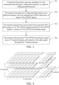
- FIG. 3 is a flowchart of a data transmission processing method according to an embodiment of this application. As shown in FIG. 3 , the method includes the following steps:
- the K antennas may be understood as all or a part of transmit antennas of the transmit end. In embodiments of this application, it is assumed that the K antennas are all transmit antennas of the transmit end.
- the data transmission processing method provided in embodiments of this application is mainly applied in a MIMO-OFDM system, where the transmit end has K transmit antennas, and the receive end has L receive antennas.
- an antenna port (Antenna Port) is used as a name.
- Each antenna port may be an antenna panel (Antenna Panel) with a plurality of antenna elements (Antenna Elements), and is configured to form an analog beam. Therefore, in embodiments of this application, each antenna port may be understood as one transmit antenna, and the transmit antenna includes correlated and/or non-correlated MIMO antennas involved in the MIMO technology.
- the transmit end may map the K orthogonal data matrices onto different frequency division multiplexing OFDM subcarriers through an OFDM modulator, to obtain K first OFDM signals.
- the transmit end may be understood as a terminal side device, or may be understood as a network side device, and is not further limited herein.
- the to-be-transmitted data may be understood as MIMO-OFDM data.
- the transmit end performs spectrum spreading on the to-be-transmitted data through K orthogonal sequences, to obtain K orthogonal data matrices.
- an orthogonal code division multiplexing (Code Division Multiplexing, CDM) method is used to precode the to-be-transmitted data, thereby obtaining a new waveform for the orthogonal radar adapted to each transmit antenna.
- CDM Code Division Multiplexing
- a transmit end performs spectrum spreading on to-be-transmitted data through K orthogonal sequences, to obtain K orthogonal data matrices, where K is an integer greater than 1; the transmit end maps the K orthogonal data matrices onto different frequency division multiplexing OFDM subcarriers, to obtain K first OFDM signals, where the first OFDM signals are spectrum spreading data matrix OFDM signals; the transmit end performs inverse fast Fourier transform IFFT processing on a k th first OFDM signal among the K first OFDM signals, to obtain a k th first OFDM time domain signal, where k is a positive integer less than or equal to K; and the transmit end maps the k th first OFDM time domain signal onto a k th transmit antenna, and transmits a first data signal through the k th transmit antenna.
- MIMO transmit antennas may be made orthogonal to each other, and MIMO spatial diversity is increased. Therefore, embodiments of this application improve the radar sensing performance.
- the performing, by a transmit end, spectrum spreading on to-be-transmitted data through K orthogonal sequences, to obtain K orthogonal data matrices includes:
- the K orthogonal sequences when the K orthogonal sequences are used to perform time domain spectrum spreading on the to-be-transmitted data, only time domain spectrum spreading may be performed, only frequency domain spectrum spreading may be performed, or time domain spectrum spreading and frequency domain spectrum spreading may be simultaneously performed.
- Kt is equal to 1, it may be understood that time domain spectrum spreading is not performed, and when K ⁇ is equal to 1, it may be understood that frequency domain spectrum spreading is not performed.
- K ' is configured or pre-configured through higher layer signaling, or K ' is determined based on a quantity of antennas.
- the higher layer signaling may include radio resource control (Radio Resource Control, RRC) signaling.
- RRC Radio Resource Control
- K t and K f are indicated through lower layer signaling.
- K t and K f may be indicated through a medium access control control element (Medium Access Control Control Element, MAC-CE) or a physical downlink control channel (Physical downlink control channel, PDCCH).
- MAC-CE Medium Access Control Control Element
- PDCCH Physical downlink control channel
- the method further includes:
- CDM spectrum spreading due to CDM spectrum spreading, there is a specific limit on a peak value of a data rate.
- CDM spectrum spreading may provide a corresponding SNR gain, and indirectly increase the data rate, this requires increasing a modulation order of quadrature amplitude modulation (Quadrature Amplitude Modulation, QAM).
- QAM Quadrature Amplitude Modulation
- an extremely high modulation order may affect performance of the radar waveform. Therefore, in embodiments of this application, the first data signal and the second data signal are alternately transmitted in time domain through the first transport block and the second transport block, thereby improving the data transmission performance and improving the radar performance.
- the first transport block may be understood as a Type-I block
- the second transport block may be understood as a Type-II block
- both the first transport block and the second transport block may be referred to as ODFM transport blocks. Because two types of ODFM transport blocks are used to dynamically switch or adjust sensing and communication waveforms, the data transmission performance may be guaranteed and the radar performance may be improved. That the first data signal is carried on the first transport block may be understood as: transmitting the first data signal on the first transport block, to be specific, transmitting a MIMO OFDM radar signal based on orthogonal CDM in the first transport block. That the second data signal is carried on the second transport block may be understood as transmitting the second data signal on the second transport block, to be specific, transmitting a conventional MIMO OFDM data signal in the second transport block.
- the first data signals transmitted on different antennas are orthogonal to each other.
- the method further includes: performing, by the transmit end, beamforming according to a transmission type and a direction of arrival DoA obtained in the first transport block, where the transmission type is single-user MIMO (Single-User MIMO) or multi-user MIMO (Multi-User MIMO).
- the transmission type is single-user MIMO (Single-User MIMO) or multi-user MIMO (Multi-User MIMO).
- the performing, by the transmit end, beamforming according to a transmission type and a DoA obtained in the first transport block includes:
- the performing, by the transmit end, beamforming according to a transmission type and a DoA obtained in the first transport block includes:
- a difference between a MIMO-OFDM transmission method of the second transport block and a conventional MIMO-OFDM transmission method is that on each MIMO layer, in addition to transmitting the data packet, the TS entity also needs to consider sensing the RO entity. Therefore, when beamforming is performed on each MIMO layer, the azimuth angles of the CO entity and the RO entity need to simultaneously be considered. In other words, the TS entity considers performing multi-directional beamforming on each MIMO layer. According to the azimuth angles of the CO entity and the RO entity, and through the MVDR algorithm, the TS entity determines to perform multi-directional beamforming on each MIMO layer.
- a quantity of beamformed beams oriented to the CO entity is one, and a quantity of beamformed beams oriented to the RO entity is at least one.
- a first beam corresponding to the first data signal and a second beam corresponding to the second data signal meet the following conditions:
- the first beam may be understood as a sensing target beam
- the second beam may be understood as a communication target beam.
- a beamforming direction that has a communication target remains unchanged, but a direction of the sensing target beam may be switched from one to another.
- the first transport block includes X sensing sub-blocks, each sensing sub-block includes N OFDM symbols, and both X and N are positive integers.
- the second transport block includes Y slots, and Y is a positive integer.
- X and Y may be configured in RRC.
- the transmit end periodically and alternately transmits the first data signal and the second data signal through the first transport block and the second transport block; or the transmit end transmits the first data signal through the first transport block or transmits the second data signal through the second transport block according to target switching signaling, where the target signaling is used for indicating to transmit a data signal through the first transport block or the second transport block.
- the first transport block and second transport block may be periodically switched, or may be switched through target signaling. It should be understood that the transmit end and the receive end should have consistent understanding of switching between the first transport block and the second transport block.
- the method further includes: receiving, by the transmit end, feedback information and first indication information transmitted by a CO entity of a receive end, where the feedback information is used for indicating that the first data signal is successfully received, and the first indication information is used for indicating a geographical location of the CO entity.
- the TS entity at the transmit end transmits an orthogonal CDM radar wave (namely, the first data signal), and simultaneously carries data.
- the CO entity at the receive end receives a related data packet
- the CO entity at the receive end needs to feed back reception success information of the data packet to the TS entity at the transmit end.
- the CO entity may notify the TS entity of a geographical location of the CO entity through control signaling.
- the TS entity may comprehensively determine which entities (namely, reflectors) belong to the CO entity and which entities belong to the RO entity according to all parameters detected in the Type-I block.
- the TS entity may calculate general coordinates of the CO entity by using an azimuth angle and range information, and calculate whether the reflector belongs to the CO entity by comparing the azimuth angle and the range information with the feedback geographical location information.
- the feedback information and the first indication information are carried on a physical uplink shared channel (Physical Uplink Shared Channel, PUSCH); or the feedback information and the first indication information are carried on a physical uplink control channel (Physical Uplink Control Channel, PUCCH).
- the first indication information is carried in higher layer signaling.
- the transmit end is used as a network side device and the receive end is used as a terminal is used for description.
- the first indication information is carried on a physical sidelink shared channel (Physical sidelink shared channel, PSSCH) or a physical sidelink signaling channel (Physical sidelink control channel, PSCCH).
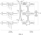
- Solution 1 A MIMO OFDM waveform technology based on CDM characteristics.
- the transmit end has K transmit antennas, and the receive end has L receive antennas.
- an orthogonal sequence (Orthogonal Sequence) c k performs spectrum spreading on data in time domain and/or frequency domain; and then the data is mapped onto different OFDM subcarriers (OFDM Subcarrier) through an OFDM modulator to obtain an OFDM signal, and then the OFDM signal is converted into an OFDM time domain signal through IFFT processing. Finally, the radar data signal is transmitted through a k th independent MIMO antenna.
- Orthogonal sequence Orthogonal Sequence
- K ' is a length of each orthogonal sequence
- K is a quantity of transmit antennas, which needs to meet K' ⁇ K.
- an OFDM transport block is a CDM-MIMO OFDM transmission resource, which includes frequency domain, time domain, and space domain.
- Frequency domain is M OFDM sub-carriers (sub-carriers).
- the TS entity includes the following several parts.
- the orthogonal sequence c k performs spectrum spreading on a data vector d k on which modulation (for example, QAM) and channel coding (for example, low density parity code, (Low Density Parity Code, LDPC)) are performed in time domain and/or frequency domain, thereby forming a two-dimensional M ⁇ N data matrix, namely, d k K f K t c k , where K f K t is an orthogonal sequence mapping symbol, which is determined according to mapping manners of different CDMs. Details are described in solution 2 below.
- Matrix data produces 1 ⁇ MN time domain signals through IFFT processing, and is transmitted at the k th transmit antenna.
- the receive end of the TS entity performs inverse spectrum spreading on a signal of each receive antenna by using c k ⁇ , and then performs coherent combining (Coherent Combining).
- An output signal is input into a sensing module (Sensor), to perform sensing on a direction of arrival ⁇ , a range range ⁇ , and Doppler f D .
- the receive end of the CO entity performs inverse spectrum spreading on a signal of each receive antenna by using c k ⁇ , and then performs coherent combining (Coherent Combining).
- the output signal is input into the FFT and a data detection module, to detect the data signal, namely, d ⁇ 1 , d ⁇ 2 , ⁇ , d ⁇ K .
- data detection is the same as conventional OFDM data packet detection. This is not repeated herein.
- introducing the orthogonal sequence c k mainly aims to improve the MIMO diversity gain, thereby enhancing radar sensing performance, transmission performance (such as a transmission data peak value) of communication may be affected to a certain extent.
- CDM spectrum spreading may use a mapping manner in a time domain and/or frequency domain direction. It is assumed that spreading factors (Spreading Factor) of OFDM in time frequency domain (namely, Time Frequency Domain, T-F domain) are respectively K t and K f .
- One orthogonal sequence c k performs spectrum spreading on each data symbol s k in the time domain direction, and each data symbol s k is then transmitted on the k th transmit antenna. Therefore, after inverse spectrum spreading is performed on the receive end through c k ⁇ , symbols s k transmitted from different transmit antennas are orthogonal, and do not interfere with each other.
- Different spectrum spreading mapping manners should be used for different requirements of an object that is sensed. This is because if the CDM spectrum spreading uses the mapping manner in the time domain direction, a maximum range of the object that may be sensed is reduced, and if the CDM spectrum spreading uses the mapping manner in the frequency domain direction, a maximum Doppler frequency of the object that may be sensed is reduced. Therefore, the TS entity may adjust a length of the time domain direction and a length of the frequency domain direction according to the required quality of service (Quality of Service, QoS) in a sensing process.
- QoS Quality of Service
- the TS entity In a scenario involving high-speed movement or few reflectors (open regions), the TS entity needs to consider a mechanism of CDM spectrum spreading in frequency domain; and in a scenario involving low-speed movement or multi-reflectors (dense regions), the TS entity needs to consider a mechanism of CDM spectrum spreading in time domain.
- a length K ' of the orthogonal sequence required for CDM spectrum spreading is at least equal to a quantity K of transmit antennas, to be specific, K' ⁇ K.
- the TS entity may consider two parameters to implement mapping in the time domain direction and the frequency domain direction.
- a spectrum spreading mapping parameter in the frequency domain direction is K t
- higher layer signaling such as RRC
- K f or K t may notify the CO entity (such as MAC-CE or PDCCH, and the like) through relatively lower layer signaling, so that the CO entity may correctly receive a data packet transmitted by the TS entity.
- the orthogonal sequence c k used in the CDM spectrum spreading mapping manner may be any orthogonal sequence or pseudo orthogonal sequence (Pseudo Orthogonal Sequence), such as Walsh code, Barker code, a PN sequence, a Zadoff-Chu sequence, and the like.
- Orthogonal Sequence such as Walsh code, Barker code, a PN sequence, a Zadoff-Chu sequence, and the like.
- Solution 3 Detection methods for a DoA, a range, and Doppler.
- the MIMO-OFDM transmit signal on the k th antenna and the n th symbol may be represented as:
- K f K t is a mapping symbol of the orthogonal sequence, and is defined as:
- d k ( m + nT ) represents the m th subcarrier data of the n th OFDM symbol
- ⁇ f is a subcarrier spacing (Sub-carrier Spacing)
- rect( t ) is a rectangular function
- a value of t ⁇ [0, 1] is 1, or otherwise a value of t ⁇ [0, 1] is
- ⁇ x ⁇ is a floor function (Floor Function) of X
- f c is a central frequency
- R x is a real function of x.
- a T ⁇ p ⁇ C K ⁇ 1 and a R ⁇ p ⁇ C L ⁇ 1 are respectively a transmit vector and a receiving vector for a target azimuth angle ⁇ p , and ⁇ , d T , and d R respectively represent a signal wavelength, a spacing of the transmit antenna, and a spacing of the receive antenna.
- [ x ] l represents an l th element of the vector x.
- CP duration is greater than a round trip delay of a farthest point target, to be specific, T cp ⁇ ⁇ max .
- the received time domain signal may be represented as: ⁇ e j 2 ⁇ m ⁇ f nT sym + qT M ⁇ ⁇ p e j 2 ⁇ f D , p nT sym + qT M
- a signal of the l th receive antenna may be represented as
- z k,l , n ' ( m ') is AWGN (Additive White Gaussian Noise) noise received on the l th receive antenna, the m' subcarrier, and the n' symbol after orthogonal sequence c k ⁇ performs inverse spectrum spreading processing.
- y k , l , n ′ ′ m ′ is used as an input signal, and detects and obtains the DoA (namely, ⁇ p ), the range (namely, ⁇ p ), and the Doppler frequency shift (namely, f D,p ) related to the P point target.
- the DoA namely, ⁇ p
- the range namely, ⁇ p
- the Doppler frequency shift namely, f D,p
- the specific required data detection algorithm is exactly the same as a method of a conventional OFDM receiver. This is not described in detail herein.
- the TS entity is the data signal [ d k ] n' , m' that is known and that is transmitted on each transmit antenna
- the TS entity may be removed from the received signal y k , l , n ′ ′ m ′ .
- the Capon method or MUSIC-related algorithms may be considered to be used.
- a spatial covariance matrix (Spatial Covariance Matrix) of the received signal needs to be first constructed. Two spatial diversity operation methods are considered.
- a first spatial diversity operation method is to only consider receive antenna diversity in a case that the received SNR is relatively low.
- y k , l , n ′ y k , l , n ′ " 0 , y k , l , n ′ " 1 , ⁇ , y k , l , n ′ " ⁇ M K f ⁇ ⁇ 1 T .
- a second spatial diversity operation method is to simultaneously consider transmit antenna diversity and receive antenna diversity in a case that the received SNR is relatively high.
- y k , l , n ′ y k , l , n ′ " 0 , y k , l , n ′ " 1 , ⁇ , y k , l , n ′ " ⁇ M K f ⁇ ⁇ 1 T .
- the spatial covariance matrix R (1) or R (2) may be used as an input by the Capon method or MUSIC-related algorithms, to obtain the DoA, namely, ⁇ p .
- a difference between algorithms of the spatial covariance matrix R (1) or R (2) is that the former obtains an SNR gain from the transmit antenna, which greatly improves accuracy of obtaining the DoA, but the latter increases a quantity of objects that may be sensed due to a diversity gain in space domain.
- an OFDM radar algorithm is considered to be used.
- the matrix Y (3) is used as an input of an OFDM radar algorithm module, to obtain the range and the Doppler frequency shift.
- a specific process of detection is as follows:
- the processed received signal y k , l , n ′ " m ′ is input into a DoA detection module, and the DoA of P targets is obtained through algorithms such as MUSIC.
- the obtained DoA through estimation is input into a receiving beamforming module, to perform receiving beamforming processing.
- a matrix signal ⁇ M K f ⁇ ⁇ ⁇ N K t ⁇ obtained by beamforming processing is input into a range and Doppler frequency shift detection module, and finally the range and the Doppler frequency shift are obtained through the OFDM radar algorithm.
- the orthogonal CDM radar waveform may be used to detect an unknown target location.
- CDM spectrum spreading there is a specific limit on a peak value of a data rate.
- CDM spectrum spreading may provide a corresponding SNR gain, and indirectly increase a data rate, this requires increasing a modulation order of QAM.
- an extremely high modulation order may affect performance of the radar waveform. Therefore, this application considers two waveforms to simultaneously implement improving of radar performance and data transmission performance.
- the TS entity may first transmit a MIMO OFDM radar signal based on orthogonal CDM in a Type-I block (Type-I Block), to detect an unknown target. Then the TS entity is periodically switched to a Type-II block (Type-II Block), to send a conventional MIMO OFDM data signal.
- a sensing and communication process of each Type-I block and Type-II block is considered as an ISAC cycle (ISAC Cycle).
- the Type-I block uses a newly designed waveform based on OFDM.
- the waveform relies on a CDM manner, to cause transmission signals on different antennas to be orthogonal to each other.
- the use of the Type-I block mainly aims to improve the sensing performance, but also guarantees the data transmission performance to a certain extent.
- the solution 3 is used to obtain the DoA, the range, and the Doppler (or velocity) of a plurality of targets.
- the Type-II block uses a classic OFDM waveform, where transmission relies on single-user MIMO (Single-User MIMO) or multi-user MIMO (Multi-User MIMO), and beamforming is performed based on the DoA obtained in the Type-I block.
- the use of the Type-II block mainly aims to improve the data performance rather than the sensing performance. Because an accurate DoA may be obtained in the Type-I block, thereby guaranteeing beamforming accuracy, beam interference between multi-user MIMO may be suppressed accordingly.
- the sensing performance in the Type-II block may also be guaranteed to a certain extent.
- the TS entity also needs to implement a radar detection process by receiving the MIMO OFDM data signal. Because communication symbols between any two transmit antennas of the TS entity are not orthogonal, the radar detection performance cannot be guaranteed. In this case, the radar detection process may only be used as a supplemental (Supplemental) function, and implementation of an accurate radar detection process relies on the Type-I block.
- each Type-I block includes X sensing sub-blocks (Sensing Sub-block, SSB).
- the sensing sub-blocks may be referred to as synchronization blocks.
- Each sensing sub-block includes N OFDM symbols.
- Each Type-II block includes Y slots (Slots).
- X and Y may be configured in RRC.
- the use of the Type-I block and the Type-II block may be periodically and alternately switched, to form an ISAC cycle (ISAC Cycle). More effectively, the use of the Type-I block and the Type-II block may also be switched in a signaling transmitting method.
- RO entity there are two types of reflected targets.
- CO entity there are two types.
- TS entity has the capability to distinguish between the RO entity and the CO entity.
- the TS entity detects a target (such as a target with a greater volume and a less range) with a greater feature value, and obtains the related DoA, range, and Doppler.
- a target such as a target with a greater volume and a less range
- the TS entity focuses on communication terminals, namely, the CO entities, giving the communication terminals a more concentrated beam and greater energy, and ensuring QoS of these communication terminals.
- P' ⁇ K - 1 because a quantity P' of beams on which the transmit end may perform beamforming needs to be met, P' ⁇ K - 1.
- a transmit power is limited due to reasons such as power amplifier hardware.
- the TS entity selects the DoA to perform beamforming on the RO entity.
- a beamforming direction that has a communication target remains unchanged, but a direction of the sensing target beam may be switched from one to another.
- the TS entity uses a greater quantity of beams for sensing, this has a negative impact on the communication performance. For example, when a greater quantity of total beams is used for beamforming, accuracy of data beamforming decreases. Further, the more beams used to sense a target, the less energy is used for data, and the data communication received signal becomes weaker; and in other words, SNR cannot meet a communication requirement.
- the key lies in how the TS entity distinguishes the RO entity and the CO entity.
- the TS entity at the transmit end transmits an orthogonal CDM radar wave, and simultaneously carries data.
- the CO entity at the receive end receives a related data packet
- the CO entity at the receive end needs to feed back reception success information of the data packet to the TS entity at the transmit end.
- the CO entity may notify the TS entity of a geographical location of the CO entity through control signaling.
- the TS entity may comprehensively determine which entities belong to the CO entity and which entities belong to the RO entity according to all parameters detected in the Type-I block.
- the TS entity may calculate general coordinates of the CO entity by using an azimuth angle and range information, and calculate whether the reflector belongs to the CO entity by comparing the azimuth angle and range information with the feedback geographical location information.
- the CO entity may send a geographical location of the CO entity to the TS entity through PUSCH, MAC-CE, or higher layer signaling and with reference to feedback information.
- the higher layer signaling is sufficient to ensure delivery of the geographical location.
- the TS entity knows that the DoA and the CO entity related to the CO entity only need to feed back a rank indicator (Rank indicator, RI) and a channel quality indicator (Channel quality indicator, CQI), and do not need to feed back a precoding matrix indicator (Precoding matrix indicator, PMI). Because feedback of the PMI requires a large amount of signaling overhead to support, this can alleviate the signaling overhead for multi-user MIMO.
- rank indicator Rank indicator
- CQI channel quality indicator
- PMI precoding matrix indicator
- Solution 5 Design for a MIMO-OFDM waveform in the Type-II block.
- the TS entity When designing the MIMO-OFDM waveform in the Type-II block, the TS entity needs to consider how many MIMO layers (Layer) are generated.
- the transmit end In a conventional MIMO-OFDM system, if I MIMO layers may be provided to the transmit end, the transmit end needs to decide I precoding, to send independent data packets on each MIMO layer. Therefore, a maximum amount of data that a MIMO system may transmit is determined by I MIMO layers.
- the MIMO-OFDM transmission method in the Type-II block is different from the conventional MIMO-OFDM transmission method.
- the TS entity On each MIMO layer, in addition to transmitting the data packet, the TS entity also needs to consider sensing the RO entity. Therefore, when beamforming is performed on each MIMO layer, the azimuth angles of the CO entity and the RO entity need to be simultaneously considered. In other words, the TS entity considers performing multi-directional beamforming on each MIMO layer. According to the azimuth angles of the CO entity and the RO entity, and through the MVDR algorithm, the TS entity determines to perform multi-directional beamforming on each MIMO layer. In each MIMO layer, a quantity of beamformed beams oriented to the CO entity is one, and a quantity of beamformed beams oriented to the RO entity may be more than one. A specific quantity is controlled by the TS entity.
- the TS entity transmits independent data packets on different MIMO layers.
- the transmitted data packets may be for a single user or for a plurality of users.
- beamforming on different MIMO layers may be for different RO entities. This may reduce mutual interference between beams as a whole, to improve performance of the TS entity in sensing a reflector. This is because the data signals transmitted between MIMO-OFDM beams are not completely orthogonal.
- a CDM spreading factor is 4.
- one orthogonal sequence c k performs spectrum spreading on each data symbol s k in the time domain direction.
- symbols s k transmitted from different transmit antennas are orthogonal, and do not interfere with each other.
- one orthogonal sequence c k performs spectrum spreading on each data symbol s k in the frequency domain direction.
- one orthogonal sequence c k simultaneously performs spectrum spreading on each data symbol s k in the time domain direction and the frequency domain direction.
- a mapping order of orthogonal sequences may be time domain first and then frequency domain; and in addition, in other embodiments, a mapping order of the orthogonal sequences may also be in an opposite mapping order, that is, frequency domain first and then time domain.
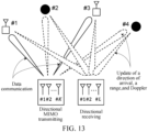
- the TS entity transmits an orthogonal CDM-MIMO OFDM radar wave. Therefore, beamforming is not performed on a transmit signal on each transmit antenna, instead beamforming is performed on an omnidirectional radar wave signal.
- the radar wave reaches different reflectors and is reflected to the TS entity.
- the TS entity receives the reflected wave by using subspace algorithms such as MUSIC, performs processing on the received signal, and obtains the DoA, the range, and the Doppler frequency shift related to the reflector.
- the TS entity deduces that the reflector #1 and the reflector #3 belong to the CO entity by using an azimuth angle and range information according to data feedback (such as the geographical location of the CO entity, and the like) of the two CO entities.
- the TS entity performs beamforming on each reflector direction, and transmits a data packet.
- the TS entity first considers the CO entity, and performs beamforming on the CO entity. Only in a case that QoS of the CO entity is ensured, the TS entity considers performing beamforming on the RO entity.
- the CO entity #1 and the CO entity #3 decode the data packet by using the conventional OFDM receiving algorithm, and then perform data feedback.
- the TS entity receives reflected waves in a manner of beamforming, performs processing on the received signal, and obtains the DoA, the range, and the Doppler frequency shift related to the reflector. It should be understood that the obtained information is for an objective of updating the DoA, the range, and the Doppler frequency shift, to compensate for errors caused by mobility of the reflector in the Type-II block.
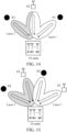
- an SU-MIMO scenario is first considered.
- one TS entity, one CO entity (reflector #2), and two RO entities (reflector #1 and reflector #3) are considered.
- the TS entity transmits the MIMO data packet to the CO entity (reflector #2), and also senses the DoA, the range, and the Doppler frequency shift of the reflector through the reflected signal from the reflector #2.
- the TS entity further needs to sense two RO entities (reflector #1 and reflector #3). Transmitting of MIMO data packets of the TS entity is completed through two MIMO layers (Two MIMO Layers). Therefore, the TS entity only considers sensing one RO entity (reflector #1 or reflector #3) when transmitting data packets on each MIMO layer.
- the TS entity when transmitting data packets on a first MIMO layer (Layer-1), the TS entity performs beamforming on two beams, one directed at the CO entity (reflector #2), and the other directed at the RO entity (reflector #1).
- the TS entity may select to direct most of the energy of the shaped beam at the CO entity, and a small part of the energy of the remaining beam is directed at the RO entity (reflector #1).
- beamforming performed on the TS entity may be implemented through algorithms such as MVDR.
- the TS entity may accurately shape beams directed at different entities.
- the Layer-1 and the Layer-2 on which beamforming is performed are simultaneously directed at the CO entity (reflector #2), and the CO entity may decode the data packet in the conventional MIMO-OFDM detection method.
- the TS entity receives echoes reflected by the three reflectors, and obtains the DoA, the range, and the Doppler frequency shift related to the reflectors through a detection algorithm of the MIMO-OFDM radar.
- the beam directed at the CO entity is a MIMO multi-layer signal, but a beam direction is consistent. Therefore, the TS entity may take the MIMO multi-layer signal as a radar signal. In other words, for the radar, the Layer-1 (Layer-1) and the Layer-2 (Layer-2) have no interference with each other.
- an interference effect of the Layer-1 on the Layer-2 should be relatively small. In this way, sensing performance of the TS entity on the RO entity (reflector #3) may be improved.
- the TS entity may arrange and distinguish the CO entity and the RO entity, select an entity with a relatively small interference effect, pair the CO entity and the RO entity, and perform beamforming on the CO entity and the RO entity, thereby reducing mutual interference between MIMO layers.
- the SU-MIMO data packet is transmitted in the Type-II block, which may ensure diversity performance of MIMO for the CO entity, and may ensure the sensing performance of all reflectors for the TS entity.
- a MU-MIMO scenario is considered.
- one TS entity, two CO entities (reflector #1 and reflector #3), and two RO entities (reflector #2 and reflector #4) are considered.
- the TS entity transmits the MIMO data packet to the CO entities (reflector #1 and reflector #3), and also senses the DoA, the range, and the Doppler frequency shift of the reflector through the reflected signal from the reflector #1 and the reflector #3.
- the TS entity further needs to sense two RO entities (reflector #2 and reflector #4). Transmitting of the MIMO data packet of the TS entity is completed through two MIMO layers (Two MIMO Layers). Therefore, when transmitting the data packet on each MIMO layer, the TS entity takes into account sensing one RO entity when being directed at the CO entity.
- the TS entity when transmitting data packets on a first MIMO layer (Layer-1), the TS entity performs beamforming on two beams, one directed at the CO entity (reflector #1), and the other directed at the RO entity (reflector #2).
- the TS entity may select to direct most of the energy of the shaped beam at the CO entity (reflector #1), and a small part of the energy of the remaining beam is directed at the RO entity (reflector #2).
- the TS entity when transmitting a data packet on a second MIMO layer (Layer-2), the TS entity performs beamforming on two beams, one directed at the CO entity (reflector #3), and the other directed at the RO entity (reflector #4).
- the TS entity may select to direct most of the energy of the shaped beam at the CO entity (reflector #3), and a small part of the energy of the remaining beam is directed at the RO entity (reflector #4).
- the Layer-1 and the Layer-2 on which beamforming is performed are simultaneously directed at different CO entities (reflector #1 and reflector #3), and the CO entity may decode the data packet in the conventional MIMO-OFDM detection method.
- the TS entity receives echoes transmitted by the four reflectors, and obtains the DoA, the range, and the Doppler frequency shift related to the reflectors through a detection algorithm of the MIMO-OFDM radar.
- beams directed at different CO entities are MIMO multi-layer signals, and have certain interference with each other. Therefore, when the TS entity uses the MIMO multi-layer signal as the radar signal, mutual interference between MIMO layers has a specific adverse impact on radar sensing.
- an interference effect of the Layer-1 on the Layer-2 should be relatively small. In this way, sensing performance of the TS entity on the RO entity (reflector #4) may be improved.
- the TS entity may also arrange and distinguish the CO entity and the RO entity, select an entity with a relatively small interference effect, pair the CO entity and the RO entity, and perform beamforming on the CO entity and the RO entity, thereby reducing mutual interference between MIMO layers.
- a degree of freedom of pairing is worse. This is because CO entities related to MU-MIMO cannot be selected.
- the MU-MIMO data packet is transmitted in the Type-II block, which may ensure diversity performance of MIMO for the CO entity, and may ensure the sensing performance of the RO reflector for the TS entity, but has a specific impact on the sensing performance of the CO entity.
- FIG. 16 is a flowchart of another data transmission processing method according to an embodiment of this application. As shown in FIG. 16 , the method includes the following steps:
- the method further includes:
- the performing, by the receive end, direction of arrival DoA detection on the received signal, to obtain a target DoA includes:
- the first spatial covariance matrix meets at least one of the following:
- the receiving, by a receive end, a target data signal includes: alternately receiving, by the receive end, the first data signal transmitted through a first transport block and a second data signal transmitted through a second transport block.
- the second data signal carries a second time domain signal, and the second time domain signal is obtained based on a conventional multiple input multiple output MIMO orthogonal frequency division multiplexing OFDM manner.
- the alternately receiving, by the receive end, the first data signal transmitted through a first transport block and a second data signal transmitted through a second transport block includes:
- the performing, by the receive end according to the target DoA, receive module beamforming processing, to obtain a received matrix signal includes: performing, by the receive end according to the target DoA and a minimum variance distortion-free response MVDR method, receiving beamforming processing, to obtain the received matrix signal.
- the feedback information and the first indication information are carried on a physical uplink shared channel PUSCH.
- the first indication information is carried in higher layer signaling.
- this embodiment is an implementation of a corresponding receive end in the embodiment shown in FIG. 3 .
- this embodiment refer to related descriptions in the embodiment shown in FIG. 3 , and to achieve the same beneficial effect. To avoid repeated descriptions, details are not repeated herein.
- an execution entity may be a data transmission processing apparatus, or a control module configured to perform data transmission processing in the data transmission processing apparatus.
- the data transmission processing apparatus performing the data transmission processing is used as an example to describe the data transmission processing apparatus provided in embodiments of this application.
- FIG. 17 is a structural diagram of a data transmission processing apparatus according to an embodiment of this application. As shown in FIG. 17 , the data transmission processing apparatus 1700 includes:
- the spectrum spreading module 1701 is specifically configured to: perform time-frequency domain spectrum spreading on the to-be-transmitted data through the K orthogonal sequences, to obtain the K orthogonal data matrices, where
- K ' is configured or pre-configured through higher layer signaling, or K ' is determined based on a quantity of antennas.
- K t and K f are indicated through lower layer signaling.
- the first mapping module 1702 is further configured to map the to-be-transmitted data onto different OFDM subcarriers, to obtain K " second OFDM signals, where K" is a positive integer less than or equal to K;
- the first data signals transmitted on different antennas are orthogonal to each other.
- the first transmit module 1704 is further configured to perform beamforming according to a transmission type and a DoA obtained in the first transport block, where the transmission type is single-user MIMO or multi-user MIMO.
- the first transmit module 1704 is specifically configured to perform beamforming on a communication object CO entity of a receive end according to the transmission type and the DoA obtained in the first transport block; and perform beamforming on a reflection object RO entity of the receive end according to the transmission type and the DoA obtained in the first transport block in a case that quality of service QoS of the CO entity is met, and the transmit end has remaining available shaped beams and/or energy that are used for transmission with the CO entity.
- the first transmit module 1704 is specifically configured to: determine at least two beam directions of each MIMO layer according to azimuth angles of a CO entity and a RO entity; and perform beamforming on the CO entity and the RO entity in the at least two beam directions for each MIMO layer.
- a quantity of beamformed beams oriented to the CO entity is one, and a quantity of beamformed beams oriented to the RO entity is at least one.
- a first beam corresponding to the first data signal and a second beam corresponding to the second data signal meet the following conditions:
- the first transport block includes X sensing sub-blocks, each sensing sub-block includes N OFDM symbols, and both X and N are positive integers.
- the second transport block includes Y slots, and Y is a positive integer.
- the first transmit module 1704 periodically and alternately transmits the first data signal and the second data signal through the first transport block and the second transport block; or transmits the first data signal through the first transport block or transmits the second data signal through the second transport block according to target switching signaling, where the target signaling is used for indicating to transmit a data signal through the first transport block or the second transport block.
- the data transmission processing apparatus 1700 further includes: a receive module, configured to receive feedback information and first indication information transmitted by a CO entity of a receive end, where the feedback information is used for indicating that the first data signal is successfully received, and the first indication information is used for indicating a geographical location of the CO entity.
- a receive module configured to receive feedback information and first indication information transmitted by a CO entity of a receive end, where the feedback information is used for indicating that the first data signal is successfully received, and the first indication information is used for indicating a geographical location of the CO entity.
- the feedback information and the first indication information are carried on a physical uplink shared channel PUSCH.
- the first indication information is carried in higher layer signaling.
- the data transmission processing apparatus may implement various processes of the method embodiment in FIG. 3 , which will not be described in detail herein again to avoid repetition.
- FIG. 18 is a structural diagram of a data transmission processing apparatus according to an embodiment of this application. As shown in FIG. 18 , the data transmission processing apparatus 1800 includes:
- the data transmission processing apparatus 1800 further includes:
- the detection module is specifically configured to construct a first spatial covariance matrix, where the first spatial covariance matrix is associated with a signal-to-noise ratio; calculate the first spatial covariance matrix by using the received signal, to obtain a second spatial covariance matrix; and calculate the second spatial covariance matrix by using a target algorithm, to obtain a target DoA, where the target algorithm is a Capon algorithm or a MUSIC algorithm.
- the first spatial covariance matrix meets at least one of the following:
- the second receive module 1801 is specifically configured to: alternately receive the first data signal transmitted through a first transport block and a second data signal transmitted through a second transport block.
- the second data signal carries a second time domain signal, and the second time domain signal is obtained based on a conventional multiple input multiple output MIMO orthogonal frequency division multiplexing OFDM manner.
- the second receive module 1801 is specifically configured to: periodically and alternately receive the first data signal transmitted through a first transport block and a second data signal transmitted through a second transport block; or receive, according to target switching signaling, the first data signal transmitted through the first transport block and the second data signal transmitted through the second transport block, where the target signaling is used for indicating to receive a data signal through the first transport block or the second transport block.
- the beamforming module is specifically configured to: perform receiving beamforming processing according to the target DoA and a minimum variance distortion-free response MVDR method, to obtain a received matrix signal.
- the data transmission processing apparatus 1800 further includes: a second transmit module, configured to transmit feedback information and first indication information to a transmit end, where the feedback information is used for indicating that the first data signal is successfully received, and the first indication information is used for indicating a geographical location of a CO entity.
- a second transmit module configured to transmit feedback information and first indication information to a transmit end, where the feedback information is used for indicating that the first data signal is successfully received, and the first indication information is used for indicating a geographical location of a CO entity.
- the feedback information and the first indication information are carried on a physical uplink shared channel PUSCH.
- the first indication information is carried in higher layer signaling.
- the data transmission processing apparatus may implement various processes of the method embodiment in FIG. 16 , which will not be described in detail herein again to avoid repetition.
- the data transmission processing apparatus in embodiments of this application may be an apparatus, an apparatus or an electronic device with an operating system, or may be a component, an integrated circuit, or a chip in a terminal.
- the apparatus may be a mobile terminal, or may be a non-mobile terminal.
- the mobile terminal may include, but is not limited to, Type of the terminal 11 listed above, and a non-mobile terminal may be a server, a network attached storage (Network Attached Storage, NAS), a personal computer (personal computer, PC), a television (television, TV), a cash machine, a self-service machine, or the like, which is not specifically limited in embodiments of this application.
- Network Attached Storage Network Attached Storage
- the data transmission processing apparatus may implement various processes of the method embodiments in FIG. 1 to FIG. 16 , and implement the same technical effect, which will not be described in detail herein again to avoid repetition.
- embodiments of this application further provide a communication device 1900, including a processor 1901, a memory 1902, and a program or an instruction stored in the memory 1902 and executable on the processor 1901, the program or instruction, when executed by the processor 1901, implements the various processes of the data transmission processing method embodiment, and may implement the same technical effect. To avoid repetition, details are not described herein again.
- Embodiments of this application further provide a terminal, including a processor and a communication interface, where the processor is configured to: perform spectrum spreading on to-be-transmitted data through K orthogonal sequences, to obtain K orthogonal data matrices, where K is an integer greater than 1; map the K orthogonal data matrices onto different frequency division multiplexing OFDM subcarriers, to obtain K first OFDM signals, where the first OFDM signals are spectrum spreading data matrix OFDM signals; and perform inverse fast Fourier transform IFFT processing on a k th first OFDM signal among the K first OFDM signals, to obtain a k th first OFDM time domain signal, where k is a positive integer less than or equal to K; and the communication interface is configured to map the k th first OFDM time domain signal onto a k th transmit antenna, and transmit a first data signal through the k th transmit antenna.
- the communication interface is configured to receive a target data signal
- the processor is configured to: perform preprocessing on the target data signal, to obtain a target time domain signal; perform discrete Fourier transform on the target time domain signal to obtain a data matrix; and perform inverse spectrum spreading processing on the data matrix by using an orthogonal sequence to obtain a received signal when the target data signal is a first data signal, where the data matrix is an orthogonal data matrix in a case that the target data signal is the first data signal.
- This terminal embodiment corresponds to the terminal side method embodiment. Each implementation process and implementation of the method embodiment may be applied to the terminal embodiment, and may achieve the same technical effect.
- FIG. 20 is a schematic diagram of a hardware structure of a terminal according to an embodiment of this application.
- the terminal 2000 includes, but is not limited to, at least a part of components such as a radio frequency unit 2001, a network module 2002, an audio output unit 2003, an input unit 2004, a sensor 2005, a display unit 2006, a user input unit 2007, an interface unit 2008, a memory 2009, and a processor 2010.
- the terminal 2000 may further include the power supply (such as a battery) for supplying power to the components.
- the power supply may be logically connected to the processor 2010 by a power management system, thereby implementing functions such as charging, discharging, and power consumption management by using the power management system.
- a terminal structure shown in FIG. 20 does not constitute a limitation to the terminal, and the terminal may include more or fewer components than those shown in the figure, or some components may be combined, or a different component deployment may be used, and details are not repeated herein.
- the input unit 2004 may include a graphics processing unit (Graphics Processing Unit, GPU) and a microphone.
- the GPU processes image data of a static picture or a video acquired by an image capturing device (for example, a camera) in a video capturing mode or an image capturing mode.
- the display unit 2006 may include a display panel, and the display panel may be configured by using a liquid crystal display, an organic light-emitting diode, or the like.
- the user input unit 2007 includes a touch panel and another input device.
- the touch panel is also referred to as a touchscreen.
- the touch panel may include two parts: a touch detection apparatus and a touch controller.
- the another input device may include, but not limited to, a physical keyboard, a functional key (such as a volume control key or a switch key), a track ball, a mouse, and a joystick, which are not described herein in detail.
- the radio frequency unit 2001 after the radio frequency unit 2001 receives downlink data from the network side device, the downlink data is processed by the processor 2010; and in addition, uplink data is transmitted to the network side device.
- the radio frequency unit 2001 includes, but is not limited to, an antenna, at least one amplifier, a transceiver, a coupler, a low noise amplifier, a duplexer, and the like.
- the radio frequency circuit may further communicate with another device through wireless communication.
- the memory 2009 may be configured to store a software program or an instruction and various data.
- the memory 109 may mainly include a program or an instruction storage area and a data storage area.
- the program or instruction storage area may store an operating system, an application program or instruction required by at least one function (such as a sound playback function and an image display function), and the like.
- the memory 2009 may include a high-speed random access memory, and may further include a non-volatile memory.
- the non-volatile memory may be a read-only memory (Read-Only Memory, ROM), a programmable read-only memory (Programmable ROM, PROM), an erasable programmable read-only memory (Erasable PROM, EPROM), an electrically erasable programmable read-only memory (Electrically EPROM, EEPROM), or a flash memory.
- ROM Read-Only Memory
- PROM programmable read-only memory
- Erasable PROM Erasable PROM
- EPROM electrically erasable programmable read-only memory
- EEPROM electrically erasable programmable read-only memory
- flash memory such as at least one magnetic disk storage device, a flash storage device, or other non-volatile solid-state storage devices.
- the processor 2010 may include one or more processing units.
- the processor 2010 may integrate an application processor and a modem, where the application processor mainly processes an operating system, a user interface, and an application program or instruction, and the modem mainly processes wireless communication, such as a baseband processor. It may be understood that the foregoing modem may either not be integrated into the processor 2010.
- the processor 210 is configured to perform spectrum spreading on to-be-transmitted data through K orthogonal sequences, to obtain K orthogonal data matrices, where K is an integer greater than 1; map the K orthogonal data matrices onto different frequency division multiplexing OFDM subcarriers, to obtain K first OFDM signals, where the first OFDM signals are spectrum spreading data matrix OFDM signals; and perform inverse fast Fourier transform IFFT processing on a k th first OFDM signal among the K first OFDM signals, to obtain a k th first OFDM time domain signal, where k is a positive integer less than or equal to K; and the radio frequency unit 2001 is configured to map the k th first OFDM time domain signal onto a k th transmit antenna, and transmit a first data signal through the k th transmit antenna.
- the radio frequency unit 2001 is configured to receive, by a receive end, a target data signal
- the processor 2010 and the radio frequency unit 2001 provided in embodiments of this application may implement various steps of the data transmission processing method embodiment, and implement the same technical effect, which will not be described in detail herein again to avoid repetition.
- Embodiments of this application further provide a network side device, including a processor and a communication interface, where the processor is configured to: perform spectrum spreading on to-be-transmitted data through K orthogonal sequences, to obtain K orthogonal data matrices, where K is an integer greater than 1; map the K orthogonal data matrices onto different frequency division multiplexing OFDM subcarriers, to obtain K first OFDM signals, where the first OFDM signals are spectrum spreading data matrix OFDM signals; and perform inverse fast Fourier transform IFFT processing on a k th first OFDM signal among the K first OFDM signals, to obtain a k th first OFDM time domain signal, where k is a positive integer less than or equal to K; and the communication interface is configured to map the k th first OFDM time domain signal onto a k th transmit antenna, and transmit a first data signal through the k th transmit antenna.
- the network side device embodiment corresponds to the network side device method embodiment. Each implementation process and implementation of the method embodiment may be
- the network side device 2100 includes: an antenna 2101, a radio frequency apparatus 2102, and a baseband apparatus 2103.
- the antenna 2101 is connected to the radio frequency apparatus 2102.
- the radio frequency apparatus 2102 receives information through the antenna 2101, and transmits the received information to the baseband apparatus 2103 for processing.
- the baseband apparatus 2103 performs processing on the to-be-transmitted information, and transmits the to-be-transmitted information to the radio frequency apparatus 2102. After performing processing on the received information, the radio frequency apparatus 2102 transmits the received information out through the antenna 2101.
- the frequency band processing apparatus may be located in the baseband apparatus 2103, and the method performed by the network side device in the foregoing embodiment may be implemented in the baseband apparatus 2103.
- the baseband apparatus 2103 includes a processor 2104 and a memory 2105.
- the baseband apparatus 2103 may include, for example, at least one baseband board, and a plurality of chips are arranged on the baseband board. As shown in FIG. 21 , for example, one of the chips is a processor 2104, and is connected to the memory 2105, to invoke the program in the memory 2105, and to perform the network side device operation shown in the foregoing method embodiments.
- the baseband apparatus 2103 may further include a network interface 2106 used for exchanging information with the radio frequency apparatus 2102.
- the interface is a common public radio interface (common public radio interface, CPRI).
- the network side device of this embodiment of this application further includes: an instruction or a program stored in the memory 2105 and executable on the processor 2104.
- the processor 2104 invokes the instruction or program in the memory 2105 to perform the method performed by each module shown in FIG. 18 , and implements the same technical effect, which will not be described in detail herein again to avoid repetition.
- Embodiments of this application further provide a readable storage medium storing therein a program or instruction.
- the program or instruction when executed by a processor, implements various processes of the embodiments of the data transmission processing method, and may implement the same technical effect, which will not be described in detail herein again to avoid repetition.
- the processor is a processor in the electronic device described in the foregoing embodiment.
- the readable storage medium includes a computer-readable storage medium, for example, a Read-Only Memory (Read-Only Memory, ROM), a Random Access Memory (Random Access Memory, RAM), a magnetic disk, an optical disc or the like.
- Embodiments of this application further provide a chip.
- the chip includes a processor and a communication interface.
- the communication interface is coupled to the processor.
- the processor is configured to run a program or an instruction to implement various processes of the data transmission processing method embodiment, and may implement the same technical effects, which will not be described in detail herein again to avoid repetition.
- chip mentioned in the embodiments of this application may further be referred to as a system-level chip, a system chip, a chip system, a system on chip, or the like.
- Embodiments of this application further provide a computer program product, being stored in a non-volatile storage medium, where the computer program product, when executed by a processor, implements various processes of the data transmission processing method embodiment, and may implement the same technical effects. To avoid repetition, details are not described herein again.
- the foregoing embodiment methods may be implemented by using software in combination with a necessary universal hardware platform. Certainly, the embodiment methods may also be implemented by using hardware, but the former is a better implementation in many cases. Based on such an understanding, the technical solutions of this application essentially, or the part contributing to the related art, may be presented in the form of a computer software product.
- the computer software product is stored in a storage medium (for example, a ROM/RAM, a magnetic disk, or an optical disc) including several instructions to enable a terminal (which may be a mobile phone, a computer, a server, an air conditioner, a base station, or the like) to perform the methods described in embodiments of this application.
Landscapes
- Engineering & Computer Science (AREA)
- Signal Processing (AREA)
- Computer Networks & Wireless Communication (AREA)
- Physics & Mathematics (AREA)
- Discrete Mathematics (AREA)
- General Physics & Mathematics (AREA)
- Mathematical Physics (AREA)
- Radio Transmission System (AREA)
- Radar Systems Or Details Thereof (AREA)
Abstract
Description
- This application claims priority to
Chinese Patent Application No. 202110909085.5, filed in China on August 09, 2021 - This application belongs to the field of communication technologies, and in particular, to a data transmission processing method and apparatus, a communication device, and a storage medium.
- With the development of communication technologies, to implement integrated sensing and communication (Integrated Sensing And Communication, ISAC) in communication, usually a manner in which different subcarriers are mapped onto different transmit antennas to perform spectrum interleaving is used to implement mutual orthogonality between transmit antennas. However, a disadvantage of a multiple input multiple output (Multiple Input Multiple Output, MIMO)-orthogonal frequency division multiplex (Orthogonal frequency division multiplex, OFDM) radar waveform is: Because the subcarriers mapped onto each transmit antenna are staggered at periodic intervals, and a quantity of intervals is determined by a quantity of transmit antennas. This has a great impact on a maximum sensing range. For example, it is assumed that the quantity of transmit antennas is N, and a quantity of periodic intervals of the mapped subcarriers is at least N, the maximum range that a radar may sense is reduced by N times. Therefore, there is a problem in the related art that radar sensing performance is poor.
- Embodiments of this application provide a data transmission processing method and apparatus, a communication device, and a readable storage medium, to resolve a problem of poor radar sensing performance.
- According to a first aspect, a data transmission processing method is provided, including:
- performing, by a transmit end, spectrum spreading on to-be-transmitted data through K orthogonal sequences, to obtain K orthogonal data matrices, where K is an integer greater than 1;
- mapping, by the transmit end, the K orthogonal data matrices onto different frequency division multiplexing OFDM subcarriers, to obtain K first OFDM signals, where the first OFDM signals are spectrum spreading data matrix OFDM signals;
- performing, by the transmit end, inverse fast Fourier transform IFFT processing on a kth first OFDM signal among the K first OFDM signals, to obtain a kth first OFDM time domain signal, where k is a positive integer less than or equal to K; and
- mapping, by the transmit end, the kth first OFDM time domain signal onto a kth transmit antenna, and transmitting a first data signal through the kth transmit antenna.
- According to a second aspect, a data transmission processing method is provided, including:
- receiving, by a receive end, a target data signal;
- performing, by the receive end, preprocessing on the target data signal, to obtain a target time domain signal;
- performing, by the receive end, discrete Fourier transform on the target time domain signal to obtain a data matrix; and
- performing, by the receive end by using an orthogonal sequence, inverse spectrum spreading processing on the data matrix to obtain a received signal in a case that the target data signal is a first data signal, where
- the data matrix is an orthogonal data matrix in a case that the target data signal is the first data signal.
- According to a third aspect, a data transmission processing apparatus is provided, including:
- a spectrum spreading module, configured to perform spectrum spreading on to-be-transmitted data through K orthogonal sequences, to obtain K orthogonal data matrices, where K is an integer greater than 1;
- a first mapping module, configured to map the K orthogonal data matrices onto different frequency division multiplexing OFDM subcarriers, to obtain K first OFDM signals, where the first OFDM signals are spectrum spreading data matrix OFDM signals;
- a first transformation module, configured to perform inverse fast Fourier transform IFFT processing on a kth first OFDM signal among the K first OFDM signals, to obtain a kth first OFDM time domain signal, where k is a positive integer less than or equal to K; and
- a first transmit module, configured to map the kth first OFDM time domain signal onto a kth transmit antenna, and transmit a first data signal through the kth transmit antenna.
- According to a fourth aspect, a data transmission processing apparatus is provided, including:
- a second receive module, configured to receive, by a receive end, a target data signal;
- a preprocessing module, configured to perform, by the receive end, preprocessing on the target data signal, to obtain a target time domain signal;
- a second transformation module, configured to perform discrete Fourier transform on the target time domain signal to obtain a data matrix; and
- an inverse spectrum spreading module, configured to perform, by using an orthogonal sequence, inverse spectrum spreading processing on the data matrix to obtain a received signal in a case that the target data signal is a first data signal, wherein
- the data matrix is an orthogonal data matrix in a case that the target data signal is the first data signal.
- According to a fifth aspect, a terminal is provided, including a processor, a memory, and a program or an instruction stored in the memory and executable on the processor, where the program or instruction, when executed by the processor, implements the steps of the method according to the first aspect, or implements the steps of the method according to the second aspect.
- According to a sixth aspect, a terminal is provided, including a processor and a communication interface, where the processor is configured to: perform spectrum spreading on to-be-transmitted data through K orthogonal sequences, to obtain K orthogonal data matrices, where K is an integer greater than 1; map the K orthogonal data matrices onto different frequency division multiplexing OFDM subcarriers, to obtain K first OFDM signals, where the first OFDM signals are spectrum spreading data matrix OFDM signals; and perform inverse fast Fourier transform IFFT processing on a kth first OFDM signal among the K first OFDM signals, to obtain a kth first OFDM time domain signal, where k is a positive integer less than or equal to K; and the communication interface is configured to map the kth first OFDM time domain signal onto a kth transmit antenna, and transmit a first data signal through the kth transmit antenna; or the communication interface is configured to receive a target data signal, and the processor is configured to: perform preprocessing on the target data signal, to obtain a target time domain signal; perform discrete Fourier transform on the target time domain signal to obtain a data matrix; and perform inverse spectrum spreading processing on the data matrix by using an orthogonal sequence to obtain a received signal when the target data signal is a first data signal, where the data matrix is an orthogonal data matrix in a case that the target data signal is the first data signal.
- According to a seventh aspect, a network side device is provided, where the network side device includes a processor, a memory, and a program or an instruction stored in the memory and executable on the processor, where the program or instruction, when executed by the processor, performs the steps of the method according to the first aspect.
- According to an eighth aspect, a network side device is provided, including a processor and a communication interface, where the processor is configured to: perform spectrum spreading on to-be-transmitted data through K orthogonal sequences, to obtain K orthogonal data matrices, where K is an integer greater than 1; map the K orthogonal data matrices onto different frequency division multiplexing OFDM subcarriers, to obtain K first OFDM signals, where the first OFDM signals are spectrum spreading data matrix OFDM signals; and perform inverse fast Fourier transform IFFT processing on a kth first OFDM signal among the K first OFDM signals, to obtain a kth first OFDM time domain signal, where k is a positive integer less than or equal to K; and the communication interface is configured to map the kth first OFDM time domain signal onto a kth transmit antenna, and transmit a first data signal through the kth transmit antenna.
- According to a ninth aspect, a readable storage medium is provided, storing a program or an instruction, where the program or instruction, when executed by a processor, implements the steps of the method according to the first aspect, or implements the steps of the method according to the second aspect.
- According to a tenth aspect, embodiments of this application provide a chip, including a processor and a communication interface, where the communication interface is coupled to the processor, and the processor is configured to run a program or an instruction, to implement the steps of the method according to the first aspect, or implement the steps of the method according to the second aspect.
- According to a twelfth aspect, a computer program/program product is provided, being stored in a storage medium, where the computer program/program product, when executed by at least one processor, implements the method according to the first aspect, or implements the method according to the second aspect.
- In embodiments of this application, a transmit end performs spectrum spreading on to-be-transmitted data through K orthogonal sequences, to obtain K orthogonal data matrices, where K is an integer greater than 1; the transmit end maps the K orthogonal data matrices onto different frequency division multiplexing OFDM subcarriers, to obtain K first OFDM signals, where the first OFDM signals are spectrum spreading data matrix OFDM signals; the transmit end performs inverse fast Fourier transform IFFT processing on a kth first OFDM signal among the K first OFDM signals, to obtain a kth first OFDM time domain signal, where k is a positive integer less than or equal to K; and the transmit end maps the kth first OFDM time domain signal onto a kth transmit antenna, and transmits a first data signal through the kth transmit antenna. In this way, because spectrum spreading is performed on the to-be-transmitted data through the K orthogonal sequences, MIMO transmit antennas may be made orthogonal to each other, and MIMO spatial diversity is increased. Therefore, embodiments of this application improve the radar sensing performance.
-
-
FIG. 1 is a structural diagram of a network system to which an embodiment of this application may be applied; -
FIG. 2 is an example diagram of an ISAC model applied to an embodiment of this application; -
FIG. 3 is a flowchart of a data transmission processing method according to an embodiment of this application; -
FIG. 4 is a schematic diagram of a structure of an OFDM transport block in a data transmission processing method according to an embodiment of this application; -
FIG. 5 is anexample flowchart 1 of a data transmission processing method according to an embodiment of this application; -
FIG. 6 is anexample flowchart 2 of a data transmission processing method according to an embodiment of this application; -
FIG. 7 is an example diagram of a detection flow of a DoA, a range, and a Doppler frequency shift in a data transmission processing method according to an embodiment of this application; -
FIG. 8 is aschematic flowchart 3 of a data transmission processing method according to an embodiment of this application; -
FIG. 9 is an example diagram 1 of spectrum spreading of a data transmission processing method according to an embodiment of this application; -
FIG. 10 is anexample flowchart 2 of spectrum spreading of a data transmission processing method according to an embodiment of this application; -
FIG. 11 is anexample flowchart 3 of spectrum spreading of a data transmission processing method according to an embodiment of this application; -
FIG. 12 is anexample flowchart 4 of a data transmission processing method according to an embodiment of this application; -
FIG. 13 is an example flowchart 5 of a data transmission processing method according to an embodiment of this application; -
FIG. 14 is anexample flowchart 6 of a data transmission processing method according to an embodiment of this application; -
FIG. 15 is an example flowchart 7 of a data transmission processing method according to an embodiment of this application; -
FIG. 16 is a flowchart of another data transmission processing method according to an embodiment of this application; -
FIG. 17 is a structural diagram of a data transmission processing apparatus according to an embodiment of this application; -
FIG. 18 is a structural diagram of another data transmission processing apparatus according to an embodiment of this application; -
FIG. 19 is a structural diagram of a communication device according to an embodiment of this application; -
FIG. 20 is a structural diagram of a terminal according to an embodiment of this application; and -
FIG. 21 is a structural diagram of a network side device according to an embodiment of this application. - The technical solutions in embodiments of this application are clearly described below with reference to the accompanying drawings in embodiments of this application. Apparently, the described embodiments are merely some rather than all of embodiments of this application. All other embodiments obtained by a person of ordinary skill in the art based on embodiments of this application shall fall within the protection scope of this application.
- In the specification and claims of this application, terms "first" and "second" are used to distinguish similar objects, but are not used to describe a specific sequence or order. It may be understood that the terms used in such a way is interchangeable in proper circumstances, so that embodiments of this application can be implemented in other sequences than the sequence illustrated or described herein. In addition, objects distinguished by "first" and "second" are usually of Type, and the number of objects is not limited. For example, a first object may be one or more than one. In addition, in the specification and claims, "and/or" means at least one of the connected objects, and the character "/" generally indicates an "or" relation between associated objects.
- It should be noted that, the technology described in embodiments of this application is not limited to a long term evolution (Long Term Evolution, LTE)/LTE evolution (LTE-Advanced, LTE-A) system, but may further be used in other wireless communication systems, such as code division multiple access (Code Division Multiple Access, CDMA), time division multiple access (Time Division Multiple Access, TDMA), frequency division multiple access (Frequency Division Multiple Access, FDMA), orthogonal frequency division multiple access, (Orthogonal Frequency Division Multiple Access, OFDMA), single-carrier frequency-division multiple access (Single-carrier Frequency-Division Multiple Access, SC-FDMA), and other systems. The terms "system" and "network" in embodiments of this application are often used interchangeably, and the described technologies may be used both for the systems and radio technologies mentioned above and may also be used for other systems and radio technologies. The following descriptions describe a new radio (New Radio, NR) system for the obj ective of being used as an example, and NR terms are used in most of the descriptions below. These technologies may also be applied to applications other than NR system applications, such as a 6th generation (6th Generation, 6G) communication system.
-
FIG. 1 is a block diagram of a wireless communication system to which an embodiment of this application may be applied. The wireless communication system includes a terminal 11 and anetwork side device 12. The terminal 11 may be a terminal side device such as a mobile phone, a tablet personal computer (Tablet Personal Computer), a laptop computer (Laptop Computer), or referred to as a notebook computer, a personal digital assistant (Personal Digital Assistant, PDA), a palmtop computer, a netbook, an ultra-mobile personal computer (ultra-mobile personal computer, UMPC), a mobile internet device (Mobile Internet Device, MID), an augmented reality (augmented reality, AR)/virtual reality (virtual reality, VR) device, a robot, a wearable device (Wearable Device), vehicle user equipment (Vehicle User Equipment, VUE), pedestrian user equipment (Pedestrian User Equipment, PUE), and a smart home (a home device with a wireless communication function, such as a refrigerator, a television, a washing machine, or a piece of furniture, and the like). The wearable device includes: a smart watch, a smart bracelet, smart headphones, smart glasses, smart jewelry (a smart bracelet, a smart bracelet, a smart ring, a smart necklace, a smart anklet, a smart anklet, and the like), a smart wristband, smart clothing, a game console, and the like. It should be noted that in embodiments of this application, a specific type of the terminal 11 is not limited. Thenetwork side device 12 may be a base station or a core network device, where the base station may be referred to as a NodeB, an evolved NodeB, an access point, a base transceiver station (Base Transceiver Station, BTS), a radio base station, a radio transceiver, a basic service set (Basic Service Set, BSS), an extended service set (Extended Service Set, ESS), a NodeB, an evolved NodeB (eNB), a household NodeB, a household evolved NodeB, a wireless local area network (Wireless Local Area Network, WLAN) access point, a wireless fidelity (wireless fidelity, WiFi) node, a transmitting receiving point (Transmitting Receiving Point, TRP) or some other proper terms in the field. Provided that the same technical effect is achieved, the base station is not limited to a specific technical vocabulary. It is to be noted that, in embodiments of this application, only a base station in the NR system is used as an example, but a specific type of the base station is not limited. - For ease of understanding, some contents involved in embodiments of this application are described below:
- 1. ISAC model.
- There are two types of ISAC models involved in embodiments of this application; and a first model is a co-located antenna based device-free sensing (Co-located Antenna based Device-free Sensing) system. A second model is a distributed antenna based device-free sensing (Distributed Antenna based Device-free Sensing) system. As shown in
FIG. 2 , when the first model is used, azimuth angles of a transmit end and a receive end are the same. That is, θ 1 = θ 2. When the second model is used, the azimuth angles of the transmit end and the receive end are different. That is, θ 1 ≠ θ 2. However, in the second model, θ 1 may be calculated by θ 2. Therefore, performance that may be achieved by using the two models should be equivalent. In embodiments of this application, the first model is mainly used as an example for description. - In the ISAC, three entities are mainly considered. A first entity is an ISAC entity, namely, an entity with a transmit (including a radar wave and data information for other entities) function and a receiving (including a reflected radar wave and data information from other entities) function, which is named a TS entity (Transmitter/Sensing Entity). For example, a base station of a cellular network, or a vehicle (equipped with a radar and a communication module function) in a vehicle wireless communication technology (Vehicle To Everything, V2X) application.
- Optionally, the receiving function of the TS entity refers to receiving radar wave information transmitted and reflected by the TS entity. For the sake of simplicity and without affecting a technical description of this application, the TS entity does not receive data packets transmitted by other entities.
- A second entity is a reflected target entity. In other words, a radar wave is reflected when reaching one target entity, and the TS entity senses a direction of arrival (Direction of Arrival), a range (Range), and Doppler (Doppler) related to the target entity through the reflected wave. The second entity is named a RO entity (Reflect Object Entity). The RO entity does not need to have a transmit function and a receiving function. For example, a conventional vehicle without a communication function, and the like.
- A third entity is a data receiving entity. In other words, the TS entity transmits the radar wave and further carries communication data. The data receiving entity is only interested in communication data. Therefore, the data receiving entity is equipped with a communication receive module. The third entity is named a CO entity (Communication Object Entity). The CO entity receives the communication data and also reflects the radar wave. For example, a terminal in a cellular network service, a vehicle in a V2X application (at least equipped with a communication receive module function), and the like.
- The TS entity has a sensing function and a communication function, mainly providing sensing of an object and a communication service to the terminal. Each TS entity includes one transmitter and one receiver. The transmitter and the receiver are located at a same location, but are physically separated from each other and have no signal interference with each other. Information may be exchanged between the transmitter and the receiver. Therefore, the receiver knows data information transmitted by the transmitter for use in data processing by the radar. In addition, each transmitter is equipped with K transmit antennas, and each receiver is equipped with L receive antennas.
- The TS entity senses PRO RO entities, and mainly detects the DoA, the range, and the Doppler frequency shift. In addition, the TS entity senses PRO CO entities in a similar manner, and also provides the communication service. A quantity P of entities sensed by the TS entity meets: P = PRO + PCO. Each CO entity needs to receive a data packet transmitted by the TS entity.
- The use of a millimeter wave plays a catalyst role in the MIMO radar. Inherent characteristics (such as a great bandwidth and a high frequency) of the millimeter wave may effectively implement benefits of a small-size antenna and a high resolution, and also greatly increase a transmission rate of communication data. Another benefit of the MIMO radar is that the MIMO radar may simultaneously sense a plurality of reflectors, and effectively identify locations of different objects. Therefore, the MIMO radar is an indispensable technology in the field of integrated sensing and communication.
- In a case that a reflector is unknown, transmit antennas of the MIMO radar need to be orthogonalized. In other words, each transmit antenna needs to transmit an independent omnidirectional radar waveform. The reason why the transmit antennas of the MIMO radar are orthogonal is that in the absence of reflector location information, the MIMO radar transmits detection signals in all directions in space, thereby providing a constant power at any location. Therefore, the MIMO radar is based on an omnidirectional antenna, and the DoA may be effectively sensed through MIMO multi-diversity characteristics and the method using Capon.
- The OFDM radar is a new technology that may be used in a radio system for an objective of integrated communication and radar. When transmitting an OFDM small data packet, the OFDM radar may produce a radar image and a related surrounding environment by receiving and processing echoes of a transmit signal.
- After performing discrete Fourier transform (Discrete Fourier Transform, DFT) processing on the echo received signal, the OFDM radar mainly optimizes the echo received signal by using a maximum likelihood estimation (Maximum Likelihood Estimation, MLE) algorithm, and finally obtains information in a delay-doppler domain (Delay-Doppler Domain, DD domain) by using dual processing of fast Fourier transform (Fast Fourier Transform, FFT) and inverse fast Fourier transform (Inverse Fast Fourier Transform, IFFT), thereby accurately obtaining a range and Doppler information.
- Optionally, the OFDM radar wave does not need to perform optimization on transmission data, because in a detection process, the received data symbol is removed before being converted into the DD domain. Therefore, a requirement of the OFDM radar for the transmission data may not need to be considered.
- The MIMO-OFDM radar combines characteristics of the MIMO radar and the OFDM radar, and is also a recently proposed new technology. The MIMO-OFDM radar has detection capabilities of both the MIMO radar and the OFDM radar. Therefore, compared with a single-technology radar, the radar has better performance such as a greater detection range, a higher speed, and a better angle, and has a stronger communication capability. For example, region surveillance of a plurality of portable wireless networks may be implemented through the MIMO-OFDM radar.
- The MIMO-OFDM radar for multi-user access may be implemented with OFDM signals on which spectrum interleaving is performed. In other words, a quantity of spacings of subcarriers and a quantity of MIMO transmit antennas need to remain the same. Because all antennas only transmit subcarrier channels that are independent of each other, interference of transmission signals between different antennas may be considered to be zero. In addition, because each antenna transmits an independent full-bandwidth radar signal, a diversity gain of MIMO is improved. Therefore, a radar resolution function is strong.
- Sensing of the direction of arrival (Direction of Arrival, DoA) may rely on a conventional subspace-based algorithm, for example, an algorithm such as a multiple signal classification (Multiple Signal Classification, MUSIC) algorithm, an estimation of signal parameters using rotational invariance techniques (Estimation of Signal Parameters using Rotational Invariance Techniques, ESPRIT) algorithm, a matrix pencil (Matrix Pencil) algorithm, and the like. The algorithm based on the subspace is mainly aimed at sensing of an unknown reflection object.
- In addition, beamforming of a known obj ect may rely on a conventional algorithm, such as a Capon method, namely, a minimum variance distortionless response (Minimum Variance Distortionless Response, MVDR), a delay and sum beamformer (Delay and sum Beamformer), and a signal-to-noise ratio (Signal-to-Noise Ratio, SNR) maximizer (maximizer), and the like.
- The data transmission processing method provided in embodiments of this application is described in detail below by using some embodiments and application scenarios with reference to the accompanying drawings.
-
FIG. 3 is a flowchart of a data transmission processing method according to an embodiment of this application. As shown inFIG. 3 , the method includes the following steps: - step 301: A transmit end performs spectrum spreading on to-be-transmitted data through K orthogonal sequences, to obtain K orthogonal data matrices, where K is an integer greater than 1;
- step 302: The transmit end maps the K orthogonal data matrices onto different frequency division multiplexing OFDM subcarriers, to obtain K first OFDM signals, where the first OFDM signals are spectrum spreading data matrix OFDM signals;
- step 303: The transmit end performs inverse fast Fourier transform IFFT processing on a kth first OFDM signal among the K first OFDM signals, to obtain a kth first OFDM time domain signal, where k is a positive integer less than or equal to K; and
- step 304: The transmit end maps the kth first OFDM time domain signal onto a kth transmit antenna, and transmits a first data signal through the kth transmit antenna.
- It should be understood that the K antennas may be understood as all or a part of transmit antennas of the transmit end. In embodiments of this application, it is assumed that the K antennas are all transmit antennas of the transmit end.
- The data transmission processing method provided in embodiments of this application is mainly applied in a MIMO-OFDM system, where the transmit end has K transmit antennas, and the receive end has L receive antennas. In an actual system, generally, an antenna port (Antenna Port) is used as a name. Each antenna port may be an antenna panel (Antenna Panel) with a plurality of antenna elements (Antenna Elements), and is configured to form an analog beam. Therefore, in embodiments of this application, each antenna port may be understood as one transmit antenna, and the transmit antenna includes correlated and/or non-correlated MIMO antennas involved in the MIMO technology.
- Optionally, the transmit end may map the K orthogonal data matrices onto different frequency division multiplexing OFDM subcarriers through an OFDM modulator, to obtain K first OFDM signals. The transmit end may be understood as a terminal side device, or may be understood as a network side device, and is not further limited herein.
- The K orthogonal sequences may be represented by C, and C = [c1, c2, ··· , c K ], where a kth orthogonal sequence c k may be represented in a vector form: c k = [c k,1, c k,2, ··· , c k,K' ] T, K' is a length of each orthogonal sequence, and K' ≥ K.
- It should be noted that the to-be-transmitted data may be understood as MIMO-OFDM data. The transmit end performs spectrum spreading on the to-be-transmitted data through K orthogonal sequences, to obtain K orthogonal data matrices. It may be understood that an orthogonal code division multiplexing (Code Division Multiplexing, CDM) method is used to precode the to-be-transmitted data, thereby obtaining a new waveform for the orthogonal radar adapted to each transmit antenna. In this way, the MIMO transmit antennas may be orthogonal, the MIMO spatial diversity is increased, and a detection gain of the MIMO radar is greatly improved.
- In embodiments of this application, a transmit end performs spectrum spreading on to-be-transmitted data through K orthogonal sequences, to obtain K orthogonal data matrices, where K is an integer greater than 1; the transmit end maps the K orthogonal data matrices onto different frequency division multiplexing OFDM subcarriers, to obtain K first OFDM signals, where the first OFDM signals are spectrum spreading data matrix OFDM signals; the transmit end performs inverse fast Fourier transform IFFT processing on a kth first OFDM signal among the K first OFDM signals, to obtain a kth first OFDM time domain signal, where k is a positive integer less than or equal to K; and the transmit end maps the kth first OFDM time domain signal onto a kth transmit antenna, and transmits a first data signal through the kth transmit antenna. In this way, because spectrum spreading is performed on the to-be-transmitted data through the K orthogonal sequences, MIMO transmit antennas may be made orthogonal to each other, and MIMO spatial diversity is increased. Therefore, embodiments of this application improve the radar sensing performance.
- Optionally, in some embodiments, the performing, by a transmit end, spectrum spreading on to-be-transmitted data through K orthogonal sequences, to obtain K orthogonal data matrices includes:
- performing, by the transmit end, time-frequency domain spectrum spreading on the to-be-transmitted data through the K orthogonal sequences, to obtain the K orthogonal data matrices, where
- a rule of the time-frequency domain spectrum spreading meets any of the following:
- after time domain spectrum spreading is first performed on Kt OFDM symbols, frequency domain spectrum spreading is performed on Kε subcarriers, both Kt and Kf are positive integers, and a sum of Kt and Kf is greater than 2; and
- after frequency domain spectrum spreading is first performed on the Kε subcarriers, time domain spectrum spreading is performed on the Kt OFDM symbols, both Kt and Kf are positive integers, and the sum of Kt and Kf is greater than 2.
- In embodiments of this application, when the K orthogonal sequences are used to perform time domain spectrum spreading on the to-be-transmitted data, only time domain spectrum spreading may be performed, only frequency domain spectrum spreading may be performed, or time domain spectrum spreading and frequency domain spectrum spreading may be simultaneously performed. When Kt is equal to 1, it may be understood that time domain spectrum spreading is not performed, and when Kε is equal to 1, it may be understood that frequency domain spectrum spreading is not performed.
- Optionally, a length K' of the orthogonal sequence meets: K' = KtKf , and K' > K.
- Optionally, in some embodiments, K' is configured or pre-configured through higher layer signaling, or K' is determined based on a quantity of antennas.
- In embodiments of this application, the higher layer signaling may include radio resource control (Radio Resource Control, RRC) signaling. If K' is determined based on the quantity of antennas, K' may be equal to K, or may be a preset value added to K or may be a multiple of K. This is not further limited herein.
- Optionally, Kt and Kf are indicated through lower layer signaling. For example, Kt and Kf may be indicated through a medium access control control element (Medium Access Control Control Element, MAC-CE) or a physical downlink control channel (Physical downlink control channel, PDCCH).
- Optionally, in some embodiments, the method further includes:
- mapping, by the transmit end, the to-be-transmitted data onto different OFDM subcarriers, to obtain K" second OFDM signals, where K" is a positive integer less than or equal to K;
- performing, by the transmit end, inverse fast Fourier transform IFFT processing on a kth second OFDM signal among the K" second OFDM signals, to obtain a kth second OFDM time domain signal, where k is a positive integer less than or equal to K"; and
- mapping, by the transmit end, the kth second OFDM time domain signal onto K transmit antennas through multiple input multiple output MIMO precoding or MIMO beamforming, and transmitting a second data signal through the K transmit antennas, where
- the first data signal is carried in a first transport block, the second data signal is carried in a second transport block, and the first transport block and the second transport block are alternately transmitted in time domain.
- In embodiments of this application, due to CDM spectrum spreading, there is a specific limit on a peak value of a data rate. Although CDM spectrum spreading may provide a corresponding SNR gain, and indirectly increase the data rate, this requires increasing a modulation order of quadrature amplitude modulation (Quadrature Amplitude Modulation, QAM). However, an extremely high modulation order may affect performance of the radar waveform. Therefore, in embodiments of this application, the first data signal and the second data signal are alternately transmitted in time domain through the first transport block and the second transport block, thereby improving the data transmission performance and improving the radar performance.
- The first transport block may be understood as a Type-I block, the second transport block may be understood as a Type-II block, and both the first transport block and the second transport block may be referred to as ODFM transport blocks. Because two types of ODFM transport blocks are used to dynamically switch or adjust sensing and communication waveforms, the data transmission performance may be guaranteed and the radar performance may be improved. That the first data signal is carried on the first transport block may be understood as: transmitting the first data signal on the first transport block, to be specific, transmitting a MIMO OFDM radar signal based on orthogonal CDM in the first transport block. That the second data signal is carried on the second transport block may be understood as transmitting the second data signal on the second transport block, to be specific, transmitting a conventional MIMO OFDM data signal in the second transport block.
- Optionally, in some embodiments, the first data signals transmitted on different antennas are orthogonal to each other.
- Optionally, in a case that the transmit end transmits the second data signal through the second transport block, the method further includes:
performing, by the transmit end, beamforming according to a transmission type and a direction of arrival DoA obtained in the first transport block, where the transmission type is single-user MIMO (Single-User MIMO) or multi-user MIMO (Multi-User MIMO). - Optionally, in some embodiments, the performing, by the transmit end, beamforming according to a transmission type and a DoA obtained in the first transport block includes:
- performing, by the transmit end, beamforming on a communication object CO entity of a receive end according to the transmission type and the DoA obtained in the first transport block; and
- performing, by the transmit end, beamforming on a reflection object RO entity of the receive end according to the transmission type and the DoA obtained in the first transport block in a case that quality of service QoS of the CO entity is met, and the transmit end has remaining available shaped beams and/or energy that are used for transmission with the CO entity.
- In embodiments of this application, the performing, by the transmit end, beamforming according to a transmission type and a DoA obtained in the first transport block includes:
- determining, by the transmit end, at least two beam directions of each MIMO layer according to azimuth angles of a CO entity and a RO entity; and
- performing, by the transmit end, beamforming on the CO entity and the RO entity in the at least two beam directions for each MIMO layer.
- It should be noted that in embodiments of this application, a difference between a MIMO-OFDM transmission method of the second transport block and a conventional MIMO-OFDM transmission method is that on each MIMO layer, in addition to transmitting the data packet, the TS entity also needs to consider sensing the RO entity. Therefore, when beamforming is performed on each MIMO layer, the azimuth angles of the CO entity and the RO entity need to simultaneously be considered. In other words, the TS entity considers performing multi-directional beamforming on each MIMO layer. According to the azimuth angles of the CO entity and the RO entity, and through the MVDR algorithm, the TS entity determines to perform multi-directional beamforming on each MIMO layer.
- Optionally, in each MIMO layer, a quantity of beamformed beams oriented to the CO entity is one, and a quantity of beamformed beams oriented to the RO entity is at least one.
- Optionally, in some embodiments, a first beam corresponding to the first data signal and a second beam corresponding to the second data signal meet the following conditions:
- the first beam has different beam directions in two adjacent time periods; and
- the second beam has an unchanged beam direction in different time periods.
- In embodiments of this application, the first beam may be understood as a sensing target beam, and the second beam may be understood as a communication target beam. In different time periods, a beamforming direction that has a communication target remains unchanged, but a direction of the sensing target beam may be switched from one to another.
- Optionally, the first transport block includes X sensing sub-blocks, each sensing sub-block includes N OFDM symbols, and both X and N are positive integers. The second transport block includes Y slots, and Y is a positive integer.
- In embodiments of this application, X and Y may be configured in RRC.
- Optionally, the transmit end periodically and alternately transmits the first data signal and the second data signal through the first transport block and the second transport block; or
the transmit end transmits the first data signal through the first transport block or transmits the second data signal through the second transport block according to target switching signaling, where the target signaling is used for indicating to transmit a data signal through the first transport block or the second transport block. - In embodiments of this application, the first transport block and second transport block may be periodically switched, or may be switched through target signaling. It should be understood that the transmit end and the receive end should have consistent understanding of switching between the first transport block and the second transport block.
- Optionally, in some embodiments, after the mapping, by the transmit end, the kth first OFDM time domain signal onto a kth transmit antenna, and transmitting a first data signal through the kth transmit antenna, the method further includes:
receiving, by the transmit end, feedback information and first indication information transmitted by a CO entity of a receive end, where the feedback information is used for indicating that the first data signal is successfully received, and the first indication information is used for indicating a geographical location of the CO entity. - In embodiments of this application, in the Type-I block, the TS entity at the transmit end transmits an orthogonal CDM radar wave (namely, the first data signal), and simultaneously carries data. When the CO entity at the receive end receives a related data packet, the CO entity at the receive end needs to feed back reception success information of the data packet to the TS entity at the transmit end. In addition, the CO entity may notify the TS entity of a geographical location of the CO entity through control signaling. The TS entity may comprehensively determine which entities (namely, reflectors) belong to the CO entity and which entities belong to the RO entity according to all parameters detected in the Type-I block. For example, the TS entity may calculate general coordinates of the CO entity by using an azimuth angle and range information, and calculate whether the reflector belongs to the CO entity by comparing the azimuth angle and the range information with the feedback geographical location information.
- Optionally, the feedback information and the first indication information are carried on a physical uplink shared channel (Physical Uplink Shared Channel, PUSCH); or the feedback information and the first indication information are carried on a physical uplink control channel (Physical Uplink Control Channel, PUCCH). The first indication information is carried in higher layer signaling.
- It should be understood that, in embodiments of this application, an example in which the transmit end is used as a network side device and the receive end is used as a terminal is used for description. Certainly, in a V2X application scenario, in a case that the transmit end is the terminal and the receive end is also the terminal device, the first indication information is carried on a physical sidelink shared channel (Physical sidelink shared channel, PSSCH) or a physical sidelink signaling channel (Physical sidelink control channel, PSCCH).
- To better understand this application, some specific examples are described in detail below.
- Solution 1: A MIMO OFDM waveform technology based on CDM characteristics.
- In a MIMO-OFDM system, the transmit end has K transmit antennas, and the receive end has L receive antennas.
- First, an orthogonal sequence (Orthogonal Sequence) c k performs spectrum spreading on data in time domain and/or frequency domain; and then the data is mapped onto different OFDM subcarriers (OFDM Subcarrier) through an OFDM modulator to obtain an OFDM signal, and then the OFDM signal is converted into an OFDM time domain signal through IFFT processing. Finally, the radar data signal is transmitted through a kth independent MIMO antenna.
- The orthogonal sequence c k may be represented in a vector form, namely,

Optionally, C = [c1, c2, ··· , c K ], and should meet the following requirements:
- Therefore, an orthogonal sequence variance meets the following condition: C H C = 1 or C T C* = 1, where C H is an hermitian matrix (Hermitian Matrix) of a matrix C.
- Optionally, K', and is a length of each orthogonal sequence, and K is a quantity of transmit antennas, which needs to meet K' ≥ K.
- Optionally, as shown in
FIG. 4 , an OFDM transport block is a CDM-MIMO OFDM transmission resource, which includes frequency domain, time domain, and space domain. Frequency domain is M OFDM sub-carriers (sub-carriers). Time domain is N OFDM symbols, a length of each symbol is T sym = T + T cp, T cp is a length of a cyclic prefix (Cyclic Prefix, CP), and space domain is K transmit antennas. - As shown in
FIG. 5 , the TS entity includes the following several parts. The orthogonal sequence c k performs spectrum spreading on a data vector d k on which modulation (for example, QAM) and channel coding (for example, low density parity code, (Low Density Parity Code, LDPC)) are performed in time domain and/or frequency domain, thereby forming a two-dimensional M × N data matrix, namely, d kK
f Kt c k , whereK
f Kt is an orthogonal sequence mapping symbol, which is determined according to mapping manners of different CDMs. Details are described insolution 2 below. Matrix data produces 1 × MN time domain signals through IFFT processing, and is transmitted at the kth transmit antenna. - The receive end of the TS entity performs inverse spectrum spreading on a signal of each receive antenna by using

- Similarly, as shown in
FIG. 6 , the receive end of the CO entity performs inverse spectrum spreading on a signal of each receive antenna by using
- Optionally, data detection is the same as conventional OFDM data packet detection. This is not repeated herein.
- Because in the CDM-MIMO OFDM transmission method, introducing the orthogonal sequence c k mainly aims to improve the MIMO diversity gain, thereby enhancing radar sensing performance, transmission performance (such as a transmission data peak value) of communication may be affected to a certain extent.
- Solution 2: Mapping manner of CDM.
- CDM spectrum spreading may use a mapping manner in a time domain and/or frequency domain direction. It is assumed that spreading factors (Spreading Factor) of OFDM in time frequency domain (namely, Time Frequency Domain, T-F domain) are respectively Kt and Kf. One orthogonal sequence c k performs spectrum spreading on each data symbol sk in the time domain direction, and each data symbol sk is then transmitted on the kth transmit antenna. Therefore, after inverse spectrum spreading is performed on the receive end through

- The OFDM signal may first perform spectrum spreading on Kt OFDM symbols in time domain, and then perform spectrum spreading on Kf subcarriers in frequency domain. Similarly, the OFDM signal may also first perform spectrum spreading on Kf subcarriers in frequency domain, and then perform spectrum spreading on Kt OFDM symbols in time domain. Sizes of spreading factors Kt and Kf are determined according to different services of the transmit end. When CDM spectrum spreading only uses the mapping manner in the time domain direction, Kf = 1; and CDM spectrum spreading may also only use the mapping manner in the frequency domain direction, namely, Kt = 1.
- Different spectrum spreading mapping manners should be used for different requirements of an object that is sensed. This is because if the CDM spectrum spreading uses the mapping manner in the time domain direction, a maximum range of the object that may be sensed is reduced, and if the CDM spectrum spreading uses the mapping manner in the frequency domain direction, a maximum Doppler frequency of the object that may be sensed is reduced. Therefore, the TS entity may adjust a length of the time domain direction and a length of the frequency domain direction according to the required quality of service (Quality of Service, QoS) in a sensing process. In a scenario involving high-speed movement or few reflectors (open regions), the TS entity needs to consider a mechanism of CDM spectrum spreading in frequency domain; and in a scenario involving low-speed movement or multi-reflectors (dense regions), the TS entity needs to consider a mechanism of CDM spectrum spreading in time domain.
- A length K' of the orthogonal sequence required for CDM spectrum spreading is at least equal to a quantity K of transmit antennas, to be specific, K' ≥ K. In addition, in a spectrum spreading mapping process, the TS entity may consider two parameters to implement mapping in the time domain direction and the frequency domain direction. In other words, a spectrum spreading mapping parameter in the frequency domain direction is Kt, and a spectrum spreading mapping parameter in the time domain direction is Kt . Therefore, Kf and Kt need to meet the following condition: K' = KfKt.
- In actual application, the parameter K' may be configured or pre-configured through higher layer signaling such as RRC, or may be directly configured in a transmit antenna mapping manner (to be specific, K' = K), and Kf or Kt may notify the CO entity (such as MAC-CE or PDCCH, and the like) through relatively lower layer signaling, so that the CO entity may correctly receive a data packet transmitted by the TS entity.
- The orthogonal sequence c k used in the CDM spectrum spreading mapping manner may be any orthogonal sequence or pseudo orthogonal sequence (Pseudo Orthogonal Sequence), such as Walsh code, Barker code, a PN sequence, a Zadoff-Chu sequence, and the like.
- Solution 3: Detection methods for a DoA, a range, and Doppler.
- After spectrum spreading is performed on the MIMO-OFDM signal through c k (or may be considered as orthogonal precoding), the MIMO-OFDM transmit signal on the kth antenna and the nth symbol may be represented as:

- | K

f Kt is a mapping symbol of the orthogonal sequence, and is defined as:
- dk (m + nT) represents the m th subcarrier data of the n th OFDM symbol, Δf is a subcarrier spacing (Sub-carrier Spacing), rect(t) is a rectangular function, a value of t ∈ [0, 1] is 1, or otherwise a value of t ∈ [0, 1] is 0,


- It should be understood that after inverse spectrum spreading is performed through


- Therefore, on the kth antenna, a signal t ∈ [0, NTsym ] transmitted on N OFDM symbol blocks may be represented as:

- fc is a central frequency, and

- For a pth point target, a transmit radio wave is obtained through a complex channel gain hp (including a path loss and a radar cross section (Radar Cross Section) effect), an azimuth angle θ p, a round trip delay τp , and a normalized Doppler frequency shift fD,p = 2vpfc /c, where fc , vp , and c respectively represents a central frequency, a radial velocity, and a light propagation speed.
- For the azimuth angle θp , a vector of the transmit antenna and a vector of the receive antenna may be represented as:


- For ease of description, without considering noise in a receiving process, the transmit signal reaches the pth point target and reaches the lth receive antenna through reflection. A received signal of the transmit signal may be represented as:

- [x] l represents an lth element of the vector x.
- Because e-i2πf
c τp is constant, and may be represented by

- Considering the following assumption, CP duration is greater than a round trip delay of a farthest point target, to be specific, T cp ≥ τ max.
- Therefore, after removing CP of the nth OFDM symbol and performing M sampling on the received signal, to be specific,


- In addition, because ΔfT sym ≈ ΔfT = 1, and e j2πmnΔfT
sym ≈ 1 may be considered,
- Generally, it may be assumed that T cp ≥ τ max and fD,pT « 1. Therefore, the impact of ISI and ICI does not need to be considered. In other words,


- If P point targets and K transmit antennas are considered, a signal of the lth receive antenna may be represented as

- If the orthogonal sequence


- z k,l,n'(m') is AWGN (Additive White Gaussian Noise) noise received on the lth receive antenna, the m' subcarrier, and the n' symbol after orthogonal sequence


- Therefore,

- It should be understood that the foregoing

- In addition, for the CO entity, after obtaining

- Optionally, because the TS entity is the data signal [d k ] n',m' that is known and that is transmitted on each transmit antenna, the TS entity may be removed from the received signal

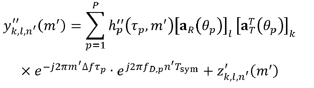

- To obtain the DoA, the Capon method or MUSIC-related algorithms may be considered to be used. In a process of the Capon method or MUSIC-related algorithms, a spatial covariance matrix (Spatial Covariance Matrix) of the received signal needs to be first constructed. Two spatial diversity operation methods are considered.
- A first spatial diversity operation method is to only consider receive antenna diversity in a case that the received SNR is relatively low. In other words, through the received signal


- By calculating the spatial covariance matrix (Spatial Covariance Matrix) of


- A second spatial diversity operation method is to simultaneously consider transmit antenna diversity and receive antenna diversity in a case that the received SNR is relatively high. In other words, through the received signal


- By calculating the spatial covariance matrix (Spatial Covariance Matrix) of


- The spatial covariance matrix R (1) or R (2) may be used as an input by the Capon method or MUSIC-related algorithms, to obtain the DoA, namely, θp.
- Optionally, a difference between algorithms of the spatial covariance matrix R (1) or R (2) is that the former obtains an SNR gain from the transmit antenna, which greatly improves accuracy of obtaining the DoA, but the latter increases a quantity of objects that may be sensed due to a diversity gain in space domain.
- Optionally, to obtain the range information and the Doppler frequency shift information, an OFDM radar algorithm is considered to be used. To more accurately obtain the range and the Doppler frequency shift, based on the estimated spatial covariance matrix R (1) of θ̂p and L × L obtained before,


- Optionally, a signal that is obtained after beamforming processing is performed may represent


- Therefore, the matrix Y (3) is used as an input of an OFDM radar algorithm module, to obtain the range and the Doppler frequency shift.
- Specifically, as shown in
FIG. 7 , a specific process of detection is as follows: The processed received signal
- A matrix signal

- Solution 4: New waveform dynamic control.
- The orthogonal CDM radar waveform may be used to detect an unknown target location. However, due to CDM spectrum spreading, there is a specific limit on a peak value of a data rate. Although CDM spectrum spreading may provide a corresponding SNR gain, and indirectly increase a data rate, this requires increasing a modulation order of QAM. However, an extremely high modulation order may affect performance of the radar waveform. Therefore, this application considers two waveforms to simultaneously implement improving of radar performance and data transmission performance.
- As shown in
FIG. 8 , two types of OFDM transport blocks are considered to implement dynamic switching or scheduling of sensing and communication waveforms. The two OFDM transport blocks are periodically and alternately used. In other words, the TS entity may first transmit a MIMO OFDM radar signal based on orthogonal CDM in a Type-I block (Type-I Block), to detect an unknown target. Then the TS entity is periodically switched to a Type-II block (Type-II Block), to send a conventional MIMO OFDM data signal. A sensing and communication process of each Type-I block and Type-II block is considered as an ISAC cycle (ISAC Cycle). - Optionally, the Type-I block uses a newly designed waveform based on OFDM. The waveform relies on a CDM manner, to cause transmission signals on different antennas to be orthogonal to each other. The use of the Type-I block mainly aims to improve the sensing performance, but also guarantees the data transmission performance to a certain extent. In the sensing process, the
solution 3 is used to obtain the DoA, the range, and the Doppler (or velocity) of a plurality of targets. - Optionally, the Type-II block uses a classic OFDM waveform, where transmission relies on single-user MIMO (Single-User MIMO) or multi-user MIMO (Multi-User MIMO), and beamforming is performed based on the DoA obtained in the Type-I block. The use of the Type-II block mainly aims to improve the data performance rather than the sensing performance. Because an accurate DoA may be obtained in the Type-I block, thereby guaranteeing beamforming accuracy, beam interference between multi-user MIMO may be suppressed accordingly. The sensing performance in the Type-II block may also be guaranteed to a certain extent.
- It should be understood that in the Type-II block, the TS entity also needs to implement a radar detection process by receiving the MIMO OFDM data signal. Because communication symbols between any two transmit antennas of the TS entity are not orthogonal, the radar detection performance cannot be guaranteed. In this case, the radar detection process may only be used as a supplemental (Supplemental) function, and implementation of an accurate radar detection process relies on the Type-I block.
- In
FIG. 8 , it is assumed that each Type-I block includes X sensing sub-blocks (Sensing Sub-block, SSB). The sensing sub-blocks may be referred to as synchronization blocks. Each sensing sub-block includes N OFDM symbols. Each Type-II block includes Y slots (Slots). X and Y may be configured in RRC. The use of the Type-I block and the Type-II block may be periodically and alternately switched, to form an ISAC cycle (ISAC Cycle). More effectively, the use of the Type-I block and the Type-II block may also be switched in a signaling transmitting method. - Generally, there are two types of reflected targets. One is a RO entity, and the other is a CO entity. It is first assumed that the TS entity has the capability to distinguish between the RO entity and the CO entity.
- In the Type-I block, the TS entity detects a target (such as a target with a greater volume and a less range) with a greater feature value, and obtains the related DoA, range, and Doppler. In the Type-II block, the TS entity focuses on communication terminals, namely, the CO entities, giving the communication terminals a more concentrated beam and greater energy, and ensuring QoS of these communication terminals. In the Type-II block, because a quantity P' of beams on which the transmit end may perform beamforming needs to be met, P' ≤ K - 1. In addition, a transmit power is limited due to reasons such as power amplifier hardware. Therefore, in the Type-II block, how to better meet a QoS requirement required by the CO entity needs to be first considered. Only when the TS entity has remaining available shaped beams and/or energy for the RO entity, the TS entity selects the DoA to perform beamforming on the RO entity. In this case, in different time periods, a beamforming direction that has a communication target remains unchanged, but a direction of the sensing target beam may be switched from one to another. This is because if the TS entity uses a greater quantity of beams for sensing, this has a negative impact on the communication performance. For example, when a greater quantity of total beams is used for beamforming, accuracy of data beamforming decreases. Further, the more beams used to sense a target, the less energy is used for data, and the data communication received signal becomes weaker; and in other words, SNR cannot meet a communication requirement.
- However, to implement the foregoing dynamic optimization control, the key lies in how the TS entity distinguishes the RO entity and the CO entity. In the Type-I block, the TS entity at the transmit end transmits an orthogonal CDM radar wave, and simultaneously carries data. When the CO entity at the receive end receives a related data packet, the CO entity at the receive end needs to feed back reception success information of the data packet to the TS entity at the transmit end. In addition, the CO entity may notify the TS entity of a geographical location of the CO entity through control signaling. The TS entity may comprehensively determine which entities belong to the CO entity and which entities belong to the RO entity according to all parameters detected in the Type-I block. For example, the TS entity may calculate general coordinates of the CO entity by using an azimuth angle and range information, and calculate whether the reflector belongs to the CO entity by comparing the azimuth angle and range information with the feedback geographical location information.
- Generally, the CO entity may send a geographical location of the CO entity to the TS entity through PUSCH, MAC-CE, or higher layer signaling and with reference to feedback information. For a low-speed CO entity, generally, the higher layer signaling is sufficient to ensure delivery of the geographical location.
- Optionally, in the Type-II block, because the TS entity knows that the DoA and the CO entity related to the CO entity only need to feed back a rank indicator (Rank indicator, RI) and a channel quality indicator (Channel quality indicator, CQI), and do not need to feed back a precoding matrix indicator (Precoding matrix indicator, PMI). Because feedback of the PMI requires a large amount of signaling overhead to support, this can alleviate the signaling overhead for multi-user MIMO.
- Solution 5: Design for a MIMO-OFDM waveform in the Type-II block.
- When designing the MIMO-OFDM waveform in the Type-II block, the TS entity needs to consider how many MIMO layers (Layer) are generated. In a conventional MIMO-OFDM system, if I MIMO layers may be provided to the transmit end, the transmit end needs to decide I precoding, to send independent data packets on each MIMO layer. Therefore, a maximum amount of data that a MIMO system may transmit is determined by I MIMO layers.
- The MIMO-OFDM transmission method in the Type-II block is different from the conventional MIMO-OFDM transmission method. On each MIMO layer, in addition to transmitting the data packet, the TS entity also needs to consider sensing the RO entity. Therefore, when beamforming is performed on each MIMO layer, the azimuth angles of the CO entity and the RO entity need to be simultaneously considered. In other words, the TS entity considers performing multi-directional beamforming on each MIMO layer. According to the azimuth angles of the CO entity and the RO entity, and through the MVDR algorithm, the TS entity determines to perform multi-directional beamforming on each MIMO layer. In each MIMO layer, a quantity of beamformed beams oriented to the CO entity is one, and a quantity of beamformed beams oriented to the RO entity may be more than one. A specific quantity is controlled by the TS entity.
- Optionally, for MIMO-OFDM transmission in the Type-II block, only data packets oriented to the CO entity need to be transmitted on the shaped beam.
- Optionally, the TS entity transmits independent data packets on different MIMO layers. The transmitted data packets may be for a single user or for a plurality of users. But beamforming on different MIMO layers may be for different RO entities. This may reduce mutual interference between beams as a whole, to improve performance of the TS entity in sensing a reflector. This is because the data signals transmitted between MIMO-OFDM beams are not completely orthogonal.
- For the
solution 2, specific examples are described below with reference toFIG. 9 to FIG. 11 . - As shown in
FIG. 9 , a CDM spreading factor is 4. CDM spectrum spreading only uses a mapping manner in a time domain direction, to be specific, Kf = 1, and Kt = 4. In other words, one orthogonal sequence c k performs spectrum spreading on each data symbol sk in the time domain direction. After inverse spectrum spreading is performed on the receive end through
- As shown in
FIG. 10 , CDM spectrum spreading may also only use a mapping manner in a frequency domain direction, namely, Kt = 1, and Kf = 4. In other words, one orthogonal sequence c k performs spectrum spreading on each data symbol sk in the frequency domain direction. - As shown in
FIG. 11 , CDM spectrum spreading may also use a mapping manner in a time domain direction and a frequency domain direction, namely Kt = 2, and Kf = 2. In other words, one orthogonal sequence c k simultaneously performs spectrum spreading on each data symbol sk in the time domain direction and the frequency domain direction. For example, a mapping order of orthogonal sequences may be time domain first and then frequency domain; and in addition, in other embodiments, a mapping order of the orthogonal sequences may also be in an opposite mapping order, that is, frequency domain first and then time domain. - For the
solution 4, specific examples are described below with reference toFIG. 12 andFIG. 13 . - By configuring related parameters of different Type-I blocks and Type-II blocks, an objective of sensing and communication may be effectively and simultaneously achieved.
- Specifically, one TS entity, two CO entities (#1 reflector and #3 reflector), and two RO entities (#2 reflector and #4 reflector) may be considered. As shown in
FIG. 12 , in the Type-I block, the TS entity transmits an orthogonal CDM-MIMO OFDM radar wave. Therefore, beamforming is not performed on a transmit signal on each transmit antenna, instead beamforming is performed on an omnidirectional radar wave signal. The radar wave reaches different reflectors and is reflected to the TS entity. The TS entity receives the reflected wave by using subspace algorithms such as MUSIC, performs processing on the received signal, and obtains the DoA, the range, and the Doppler frequency shift related to the reflector. In addition, the TS entity deduces that thereflector # 1 and thereflector # 3 belong to the CO entity by using an azimuth angle and range information according to data feedback (such as the geographical location of the CO entity, and the like) of the two CO entities. - As shown in
FIG. 13 , in the Type-II block, according to the obtained detection information and a type of a reflector, the TS entity performs beamforming on each reflector direction, and transmits a data packet. When performing beamforming on the reflector, the TS entity first considers the CO entity, and performs beamforming on the CO entity. Only in a case that QoS of the CO entity is ensured, the TS entity considers performing beamforming on the RO entity. TheCO entity # 1 and theCO entity # 3 decode the data packet by using the conventional OFDM receiving algorithm, and then perform data feedback. The TS entity receives reflected waves in a manner of beamforming, performs processing on the received signal, and obtains the DoA, the range, and the Doppler frequency shift related to the reflector. It should be understood that the obtained information is for an objective of updating the DoA, the range, and the Doppler frequency shift, to compensate for errors caused by mobility of the reflector in the Type-II block. - For the solution 5, specific examples are described below with reference to
FIG. 14 and FIG. 15 . - As shown in
FIG. 14 , an SU-MIMO scenario is first considered. In the scenario, one TS entity, one CO entity (reflector #2), and two RO entities (reflector # 1 and reflector #3) are considered. The TS entity transmits the MIMO data packet to the CO entity (reflector #2), and also senses the DoA, the range, and the Doppler frequency shift of the reflector through the reflected signal from thereflector # 2. In addition, the TS entity further needs to sense two RO entities (reflector # 1 and reflector #3). Transmitting of MIMO data packets of the TS entity is completed through two MIMO layers (Two MIMO Layers). Therefore, the TS entity only considers sensing one RO entity (reflector # 1 or reflector #3) when transmitting data packets on each MIMO layer. - Specifically, when transmitting data packets on a first MIMO layer (Layer-1), the TS entity performs beamforming on two beams, one directed at the CO entity (reflector #2), and the other directed at the RO entity (reflector #1). To ensure communication quality for the CO entity, the TS entity may select to direct most of the energy of the shaped beam at the CO entity, and a small part of the energy of the remaining beam is directed at the RO entity (reflector #1).
- Optionally, beamforming performed on the TS entity may be implemented through algorithms such as MVDR. In a case that an azimuth angle of an entity is known, the TS entity may accurately shape beams directed at different entities.
- Similarly, when transmitting data packets on a second MIMO layer (Layer-2), the TS entity performs beamforming on two beams, one directed at the CO entity (reflector #2), and the other directed at the RO entity (reflector #3). To ensure communication quality for the CO entity, the TS entity may select to direct most of the energy of the shaped beam at the CO entity, and a small part of the energy of the remaining beam is directed at the RO entity (reflector #3).
- Optionally, the Layer-1 and the Layer-2 on which beamforming is performed are simultaneously directed at the CO entity (reflector #2), and the CO entity may decode the data packet in the conventional MIMO-OFDM detection method. In addition, the TS entity receives echoes reflected by the three reflectors, and obtains the DoA, the range, and the Doppler frequency shift related to the reflectors through a detection algorithm of the MIMO-OFDM radar.
- It should be understood that the beam directed at the CO entity (reflector #2) is a MIMO multi-layer signal, but a beam direction is consistent. Therefore, the TS entity may take the MIMO multi-layer signal as a radar signal. In other words, for the radar, the Layer-1 (Layer-1) and the Layer-2 (Layer-2) have no interference with each other.
- In addition, it is worth noting that there is specific independence between a beam signal in the Layer-1 and a beam signal in the Layer-2 that are directed at the RO entity (reflector #1). Therefore, as far as the radar is concerned, an interference effect of the Layer-2 on the Layer-1 should be relatively small. In this way, sensing performance of the TS entity on the RO entity (reflector #1) may be improved.
- Similarly, an interference effect of the Layer-1 on the Layer-2 should be relatively small. In this way, sensing performance of the TS entity on the RO entity (reflector #3) may be improved.
- Optionally, the TS entity may arrange and distinguish the CO entity and the RO entity, select an entity with a relatively small interference effect, pair the CO entity and the RO entity, and perform beamforming on the CO entity and the RO entity, thereby reducing mutual interference between MIMO layers.
- Therefore, the SU-MIMO data packet is transmitted in the Type-II block, which may ensure diversity performance of MIMO for the CO entity, and may ensure the sensing performance of all reflectors for the TS entity.
- As shown in
FIG. 15 , a MU-MIMO scenario is considered. In the scenario, one TS entity, two CO entities (reflector # 1 and reflector #3), and two RO entities (reflector # 2 and reflector #4) are considered. The TS entity transmits the MIMO data packet to the CO entities (reflector # 1 and reflector #3), and also senses the DoA, the range, and the Doppler frequency shift of the reflector through the reflected signal from thereflector # 1 and thereflector # 3. In addition, the TS entity further needs to sense two RO entities (reflector # 2 and reflector #4). Transmitting of the MIMO data packet of the TS entity is completed through two MIMO layers (Two MIMO Layers). Therefore, when transmitting the data packet on each MIMO layer, the TS entity takes into account sensing one RO entity when being directed at the CO entity. - Specifically, when transmitting data packets on a first MIMO layer (Layer-1), the TS entity performs beamforming on two beams, one directed at the CO entity (reflector #1), and the other directed at the RO entity (reflector #2). To ensure communication quality for the CO entity, the TS entity may select to direct most of the energy of the shaped beam at the CO entity (reflector #1), and a small part of the energy of the remaining beam is directed at the RO entity (reflector #2).
- Similarly, when transmitting a data packet on a second MIMO layer (Layer-2), the TS entity performs beamforming on two beams, one directed at the CO entity (reflector #3), and the other directed at the RO entity (reflector #4). To ensure communication quality for the CO entity, the TS entity may select to direct most of the energy of the shaped beam at the CO entity (reflector #3), and a small part of the energy of the remaining beam is directed at the RO entity (reflector #4).
- Optionally, the Layer-1 and the Layer-2 on which beamforming is performed are simultaneously directed at different CO entities (
reflector # 1 and reflector #3), and the CO entity may decode the data packet in the conventional MIMO-OFDM detection method. In addition, the TS entity receives echoes transmitted by the four reflectors, and obtains the DoA, the range, and the Doppler frequency shift related to the reflectors through a detection algorithm of the MIMO-OFDM radar. - It should be understood that beams directed at different CO entities (
reflector # 1 and reflector #3) are MIMO multi-layer signals, and have certain interference with each other. Therefore, when the TS entity uses the MIMO multi-layer signal as the radar signal, mutual interference between MIMO layers has a specific adverse impact on radar sensing. - What is the same as SU-MIMO is that there is specific independence between a beam signal in the Layer-1 and a beam signal in the Layer-2 that are directed at the RO entity (reflector #2). Therefore, as far as the radar is concerned, an interference effect of the Layer-2 on the Layer-1 should be relatively small. In this way, sensing performance of the TS entity on the RO entity (reflector #2) may be improved.
- Similarly, an interference effect of the Layer-1 on the Layer-2 should be relatively small. In this way, sensing performance of the TS entity on the RO entity (reflector #4) may be improved.
- Optionally, the TS entity may also arrange and distinguish the CO entity and the RO entity, select an entity with a relatively small interference effect, pair the CO entity and the RO entity, and perform beamforming on the CO entity and the RO entity, thereby reducing mutual interference between MIMO layers. However, compared with SU-MIMO, a degree of freedom of pairing is worse. This is because CO entities related to MU-MIMO cannot be selected.
- The MU-MIMO data packet is transmitted in the Type-II block, which may ensure diversity performance of MIMO for the CO entity, and may ensure the sensing performance of the RO reflector for the TS entity, but has a specific impact on the sensing performance of the CO entity.
-
FIG. 16 is a flowchart of another data transmission processing method according to an embodiment of this application. As shown inFIG. 16 , the method includes the following steps: - step 1601: A receive end receives a target data signal;
- step 1602: The receive end performs preprocessing on the target data signal, to obtain a target time domain signal;
- step 1603: The receive end performs discrete Fourier transform on the target time domain signal to obtain a data matrix; and
- step 1604: The receive end performs inverse spectrum spreading processing on the data matrix by using an orthogonal sequence to obtain a received signal in a case that the target data signal is a first data signal, where
- the data matrix is an orthogonal data matrix in a case that the target data signal is the first data signal.
- Optionally, after the performing, by the receive end by using an orthogonal sequence, inverse spectrum spreading processing on the data matrix to obtain a received signal, the method further includes:
- performing, by the receive end, direction of arrival DoA detection on the received signal, to obtain a target DoA;
- performing, by the receive end according to the target DoA, receiving beamforming processing, to obtain a received matrix signal; and
- calculate, by the receive end by using an OFDM radar algorithm, the received matrix signal, to obtain a range and a Doppler frequency shift.
- Optionally, the performing, by the receive end, direction of arrival DoA detection on the received signal, to obtain a target DoA includes:
- constructing, by the receive end, a first spatial covariance matrix, where the first spatial covariance matrix is associated with a signal-to-noise ratio;
- calculating, by the receive end by using the received signal, the first spatial covariance matrix, to obtain a second spatial covariance matrix; and
- calculating, by the receive end by using a target algorithm, the second spatial covariance matrix, to obtain the target DoA, where
- the target algorithm is a Capon algorithm or a MUSIC algorithm.
- Optionally, the first spatial covariance matrix meets at least one of the following:
- in a case that the signal-to-noise ratio is less than a first preset value, the first spatial covariance matrix is constructed based on a first spatial diversity operation method, and the first spatial diversity operation method is associated with only receive antenna diversity; and
- in a case that the signal-to-noise ratio is greater than or equal to the first preset value, the first spatial covariance matrix is constructed based on a second spatial diversity operation method, and the first spatial diversity operation method is associated with transmit antenna diversity and the receive antenna diversity.
- Optionally, the receiving, by a receive end, a target data signal includes:
alternately receiving, by the receive end, the first data signal transmitted through a first transport block and a second data signal transmitted through a second transport block. - Optionally, the second data signal carries a second time domain signal, and the second time domain signal is obtained based on a conventional multiple input multiple output MIMO orthogonal frequency division multiplexing OFDM manner.
- Optionally, the alternately receiving, by the receive end, the first data signal transmitted through a first transport block and a second data signal transmitted through a second transport block includes:
- periodically and alternately receiving, by the receive end, the first data signal transmitted through the first transport block and the second data signal transmitted through the second transport block; or
- receiving, by the receive end according to target switching signaling, the first data signal transmitted through the first transport block and the second data signal transmitted through the second transport block, where the target signaling is used for indicating to receive a data signal through the first transport block or the second transport block.
- Optionally, the performing, by the receive end according to the target DoA, receive module beamforming processing, to obtain a received matrix signal includes:
performing, by the receive end according to the target DoA and a minimum variance distortion-free response MVDR method, receiving beamforming processing, to obtain the received matrix signal. - Optionally, after the receiving, by a receive end, a target data signal, the method further includes:
transmitting, by the receive end, feedback information and first indication information to a transmit end, where the feedback information is used for indicating that the first data signal is successfully received, and the first indication information is used for indicating a geographical location of a CO entity. - Optionally, the feedback information and the first indication information are carried on a physical uplink shared channel PUSCH.
- Optionally, the first indication information is carried in higher layer signaling.
- It should be noted that this embodiment is an implementation of a corresponding receive end in the embodiment shown in
FIG. 3 . For a specific implementation of this embodiment, refer to related descriptions in the embodiment shown inFIG. 3 , and to achieve the same beneficial effect. To avoid repeated descriptions, details are not repeated herein. - It should be noted that in the data transmission processing method provided in embodiments of this application, an execution entity may be a data transmission processing apparatus, or a control module configured to perform data transmission processing in the data transmission processing apparatus. In embodiments of this application, the data transmission processing apparatus performing the data transmission processing is used as an example to describe the data transmission processing apparatus provided in embodiments of this application.
-
FIG. 17 is a structural diagram of a data transmission processing apparatus according to an embodiment of this application. As shown inFIG. 17 , the datatransmission processing apparatus 1700 includes: - a
spectrum spreading module 1701, configured to perform spectrum spreading on to-be-transmitted data through K orthogonal sequences, to obtain K orthogonal data matrices, where K is an integer greater than 1; - a
first mapping module 1702, configured to map the K orthogonal data matrices onto different frequency division multiplexing OFDM subcarriers, to obtain K first OFDM signals, where the first OFDM signals are spectrum spreading data matrix OFDM signals; - a
first transformation module 1703, configured to perform inverse fast Fourier transform IFFT processing on a kth first OFDM signal among the K first OFDM signals, to obtain a kth first OFDM time domain signal, where k is a positive integer less than or equal to K; and - a first transmit
module 1704, configured to map the kth first OFDM time domain signal onto a kth transmit antenna, and transmit a first data signal through the kth transmit antenna. - Optionally, the
spectrum spreading module 1701 is specifically configured to: perform time-frequency domain spectrum spreading on the to-be-transmitted data through the K orthogonal sequences, to obtain the K orthogonal data matrices, where - a rule of the time-frequency domain spectrum spreading meets any of the following:
- after time domain spectrum spreading is first performed on Kt OFDM symbols, frequency domain spectrum spreading is performed on Kε subcarriers, both Kt and Kf are positive integers, and a sum of Kt and Kf is greater than 2; and
- after frequency domain spectrum spreading is first performed on the Kε subcarriers, time domain spectrum spreading is performed on the Kt OFDM symbols, both Kt and Kf are positive integers, and the sum of Kt and Kf is greater than 2.
- Optionally, a length K' of the orthogonal sequence meets: K' = KtKf , and K' > K.
- Optionally, K' is configured or pre-configured through higher layer signaling, or K' is determined based on a quantity of antennas.
- Optionally, Kt and Kf are indicated through lower layer signaling.
- Optionally, the
first mapping module 1702 is further configured to map the to-be-transmitted data onto different OFDM subcarriers, to obtain K" second OFDM signals, where K" is a positive integer less than or equal to K; - the
first transformation module 1703 is further configured to perform inverse fast Fourier transform IFFT processing on a kth second OFDM signal among the K" second OFDM signals, to obtain a kth second OFDM time domain signal, where k is a positive integer less than or equal to K"; and - the first transmit
module 1704 is further configured to map the kth second OFDM time domain signal onto K transmit antennas through multiple input multiple output MIMO precoding or MIMO beamforming, and transmit a second data signal through the K transmit antennas, where - the first data signal is carried in a first transport block, the second data signal is carried in a second transport block, and the first transport block and the second transport block are alternately transmitted in time domain.
- Optionally, the first data signals transmitted on different antennas are orthogonal to each other.
- Optionally, in a case that the second data signal is transmitted through the second transport block, the first transmit
module 1704 is further configured to perform beamforming according to a transmission type and a DoA obtained in the first transport block, where the transmission type is single-user MIMO or multi-user MIMO. - Optionally, the first transmit
module 1704 is specifically configured to perform beamforming on a communication object CO entity of a receive end according to the transmission type and the DoA obtained in the first transport block; and perform beamforming on a reflection object RO entity of the receive end according to the transmission type and the DoA obtained in the first transport block in a case that quality of service QoS of the CO entity is met, and the transmit end has remaining available shaped beams and/or energy that are used for transmission with the CO entity. - Optionally, the first transmit
module 1704 is specifically configured to: determine at least two beam directions of each MIMO layer according to azimuth angles of a CO entity and a RO entity; and perform beamforming on the CO entity and the RO entity in the at least two beam directions for each MIMO layer. - Optionally, in each MIMO layer, a quantity of beamformed beams oriented to the CO entity is one, and a quantity of beamformed beams oriented to the RO entity is at least one.
- Optionally, a first beam corresponding to the first data signal and a second beam corresponding to the second data signal meet the following conditions:
- the first beam has different beam directions in two adjacent time periods; and
- the second beam has an unchanged beam direction in different time periods.
- Optionally, the first transport block includes X sensing sub-blocks, each sensing sub-block includes N OFDM symbols, and both X and N are positive integers.
- Optionally, the second transport block includes Y slots, and Y is a positive integer.
- Optionally, the first transmit
module 1704 periodically and alternately transmits the first data signal and the second data signal through the first transport block and the second transport block; or transmits the first data signal through the first transport block or transmits the second data signal through the second transport block according to target switching signaling, where the target signaling is used for indicating to transmit a data signal through the first transport block or the second transport block. - Optionally, the data
transmission processing apparatus 1700 further includes:
a receive module, configured to receive feedback information and first indication information transmitted by a CO entity of a receive end, where the feedback information is used for indicating that the first data signal is successfully received, and the first indication information is used for indicating a geographical location of the CO entity. - Optionally, the feedback information and the first indication information are carried on a physical uplink shared channel PUSCH.
- Optionally, the first indication information is carried in higher layer signaling.
- The data transmission processing apparatus provided in embodiments of this application may implement various processes of the method embodiment in
FIG. 3 , which will not be described in detail herein again to avoid repetition. -
FIG. 18 is a structural diagram of a data transmission processing apparatus according to an embodiment of this application. As shown inFIG. 18 , the datatransmission processing apparatus 1800 includes: - a second receive
module 1801, configured to receive, by a receive end, a target data signal; - a
preprocessing module 1802, configured to perform, by the receive end, preprocessing on the target data signal, to obtain a target time domain signal; - a
second transformation module 1803, configured to perform discrete Fourier transform on the target time domain signal to obtain a data matrix; and - an inverse
spectrum spreading module 1804, configured to perform, by using an orthogonal sequence, inverse spectrum spreading processing on the data matrix to obtain a received signal when the target data signal is a first data signal, where - the data matrix is an orthogonal data matrix in a case that the target data signal is the first data signal.
- Optionally, the data
transmission processing apparatus 1800 further includes: - a detection module, configured to perform direction of arrival DoA detection on the received signal, to obtain a target DoA;
- a beamforming module, configured to perform receiving beamforming processing according to the target DoA, to obtain a received matrix signal; and
- a calculation module, configured to calculate the received matrix signal by using an OFDM radar algorithm, to obtain a range and a Doppler frequency shift.
- Optionally, the detection module is specifically configured to construct a first spatial covariance matrix, where the first spatial covariance matrix is associated with a signal-to-noise ratio; calculate the first spatial covariance matrix by using the received signal, to obtain a second spatial covariance matrix; and calculate the second spatial covariance matrix by using a target algorithm, to obtain a target DoA, where
the target algorithm is a Capon algorithm or a MUSIC algorithm. - Optionally, the first spatial covariance matrix meets at least one of the following:
- in a case that the signal-to-noise ratio is less than a first preset value, the first spatial covariance matrix is constructed based on a first spatial diversity operation method, and the first spatial diversity operation method is associated with only receive antenna diversity; and
- in a case that the signal-to-noise ratio is greater than or equal to the first preset value, the first spatial covariance matrix is constructed based on a second spatial diversity operation method, and the first spatial diversity operation method is associated with transmit antenna diversity and the receive antenna diversity.
- Optionally, the second receive
module 1801 is specifically configured to: alternately receive the first data signal transmitted through a first transport block and a second data signal transmitted through a second transport block. - Optionally, the second data signal carries a second time domain signal, and the second time domain signal is obtained based on a conventional multiple input multiple output MIMO orthogonal frequency division multiplexing OFDM manner.
- Optionally, the second receive
module 1801 is specifically configured to: periodically and alternately receive the first data signal transmitted through a first transport block and a second data signal transmitted through a second transport block; or receive, according to target switching signaling, the first data signal transmitted through the first transport block and the second data signal transmitted through the second transport block, where the target signaling is used for indicating to receive a data signal through the first transport block or the second transport block. - Optionally, the beamforming module is specifically configured to: perform receiving beamforming processing according to the target DoA and a minimum variance distortion-free response MVDR method, to obtain a received matrix signal.
- Optionally, the data
transmission processing apparatus 1800 further includes:
a second transmit module, configured to transmit feedback information and first indication information to a transmit end, where the feedback information is used for indicating that the first data signal is successfully received, and the first indication information is used for indicating a geographical location of a CO entity. - Optionally, the feedback information and the first indication information are carried on a physical uplink shared channel PUSCH.
- Optionally, the first indication information is carried in higher layer signaling.
- The data transmission processing apparatus provided in embodiments of this application may implement various processes of the method embodiment in
FIG. 16 , which will not be described in detail herein again to avoid repetition. - The data transmission processing apparatus in embodiments of this application may be an apparatus, an apparatus or an electronic device with an operating system, or may be a component, an integrated circuit, or a chip in a terminal. The apparatus may be a mobile terminal, or may be a non-mobile terminal. For example, the mobile terminal may include, but is not limited to, Type of the terminal 11 listed above, and a non-mobile terminal may be a server, a network attached storage (Network Attached Storage, NAS), a personal computer (personal computer, PC), a television (television, TV), a cash machine, a self-service machine, or the like, which is not specifically limited in embodiments of this application.
- The data transmission processing apparatus provided in embodiments of this application may implement various processes of the method embodiments in
FIG. 1 to FIG. 16 , and implement the same technical effect, which will not be described in detail herein again to avoid repetition. - Optionally, as shown in
FIG. 19 , embodiments of this application further provide acommunication device 1900, including aprocessor 1901, amemory 1902, and a program or an instruction stored in thememory 1902 and executable on theprocessor 1901, the program or instruction, when executed by theprocessor 1901, implements the various processes of the data transmission processing method embodiment, and may implement the same technical effect. To avoid repetition, details are not described herein again. - Embodiments of this application further provide a terminal, including a processor and a communication interface, where the processor is configured to: perform spectrum spreading on to-be-transmitted data through K orthogonal sequences, to obtain K orthogonal data matrices, where K is an integer greater than 1; map the K orthogonal data matrices onto different frequency division multiplexing OFDM subcarriers, to obtain K first OFDM signals, where the first OFDM signals are spectrum spreading data matrix OFDM signals; and perform inverse fast Fourier transform IFFT processing on a kth first OFDM signal among the K first OFDM signals, to obtain a kth first OFDM time domain signal, where k is a positive integer less than or equal to K; and the communication interface is configured to map the kth first OFDM time domain signal onto a kth transmit antenna, and transmit a first data signal through the kth transmit antenna. Alternatively, the communication interface is configured to receive a target data signal, and the processor is configured to: perform preprocessing on the target data signal, to obtain a target time domain signal; perform discrete Fourier transform on the target time domain signal to obtain a data matrix; and perform inverse spectrum spreading processing on the data matrix by using an orthogonal sequence to obtain a received signal when the target data signal is a first data signal, where the data matrix is an orthogonal data matrix in a case that the target data signal is the first data signal. This terminal embodiment corresponds to the terminal side method embodiment. Each implementation process and implementation of the method embodiment may be applied to the terminal embodiment, and may achieve the same technical effect. Specifically,
FIG. 20 is a schematic diagram of a hardware structure of a terminal according to an embodiment of this application. - The terminal 2000 includes, but is not limited to, at least a part of components such as a
radio frequency unit 2001, anetwork module 2002, anaudio output unit 2003, aninput unit 2004, asensor 2005, adisplay unit 2006, a user input unit 2007, aninterface unit 2008, amemory 2009, and aprocessor 2010. - A person skilled in the art may understand that the terminal 2000 may further include the power supply (such as a battery) for supplying power to the components. The power supply may be logically connected to the
processor 2010 by a power management system, thereby implementing functions such as charging, discharging, and power consumption management by using the power management system. A terminal structure shown inFIG. 20 does not constitute a limitation to the terminal, and the terminal may include more or fewer components than those shown in the figure, or some components may be combined, or a different component deployment may be used, and details are not repeated herein. - It should be understood that, in embodiments of this application, the
input unit 2004 may include a graphics processing unit (Graphics Processing Unit, GPU) and a microphone. The GPU processes image data of a static picture or a video acquired by an image capturing device (for example, a camera) in a video capturing mode or an image capturing mode. Thedisplay unit 2006 may include a display panel, and the display panel may be configured by using a liquid crystal display, an organic light-emitting diode, or the like. The user input unit 2007 includes a touch panel and another input device. The touch panel is also referred to as a touchscreen. The touch panel may include two parts: a touch detection apparatus and a touch controller. The another input device may include, but not limited to, a physical keyboard, a functional key (such as a volume control key or a switch key), a track ball, a mouse, and a joystick, which are not described herein in detail. - In embodiments of this application, after the
radio frequency unit 2001 receives downlink data from the network side device, the downlink data is processed by theprocessor 2010; and in addition, uplink data is transmitted to the network side device. Generally, theradio frequency unit 2001 includes, but is not limited to, an antenna, at least one amplifier, a transceiver, a coupler, a low noise amplifier, a duplexer, and the like. In addition, the radio frequency circuit may further communicate with another device through wireless communication. - The
memory 2009 may be configured to store a software program or an instruction and various data. The memory 109 may mainly include a program or an instruction storage area and a data storage area. The program or instruction storage area may store an operating system, an application program or instruction required by at least one function (such as a sound playback function and an image display function), and the like. In addition, thememory 2009 may include a high-speed random access memory, and may further include a non-volatile memory. The non-volatile memory may be a read-only memory (Read-Only Memory, ROM), a programmable read-only memory (Programmable ROM, PROM), an erasable programmable read-only memory (Erasable PROM, EPROM), an electrically erasable programmable read-only memory (Electrically EPROM, EEPROM), or a flash memory. Such as at least one magnetic disk storage device, a flash storage device, or other non-volatile solid-state storage devices. - The
processor 2010 may include one or more processing units. Optionally, theprocessor 2010 may integrate an application processor and a modem, where the application processor mainly processes an operating system, a user interface, and an application program or instruction, and the modem mainly processes wireless communication, such as a baseband processor. It may be understood that the foregoing modem may either not be integrated into theprocessor 2010. - The processor 210 is configured to perform spectrum spreading on to-be-transmitted data through K orthogonal sequences, to obtain K orthogonal data matrices, where K is an integer greater than 1; map the K orthogonal data matrices onto different frequency division multiplexing OFDM subcarriers, to obtain K first OFDM signals, where the first OFDM signals are spectrum spreading data matrix OFDM signals; and perform inverse fast Fourier transform IFFT processing on a kth first OFDM signal among the K first OFDM signals, to obtain a kth first OFDM time domain signal, where k is a positive integer less than or equal to K; and
theradio frequency unit 2001 is configured to map the kth first OFDM time domain signal onto a kth transmit antenna, and transmit a first data signal through the kth transmit antenna. - Alternatively, the
radio frequency unit 2001 is configured to receive, by a receive end, a target data signal; - the processor 210 is configured to perform preprocessing on the target data signal, to obtain a target time domain signal; and
- a second transformation module is configured to perform discrete Fourier transform on the target time domain signal to obtain a data matrix; and perform inverse spectrum spreading processing on the data matrix by using an orthogonal sequence to obtain a received signal when the target data signal is a first data signal, where
- the data matrix is an orthogonal data matrix in a case that the target data signal is the first data signal.
- The
processor 2010 and theradio frequency unit 2001 provided in embodiments of this application may implement various steps of the data transmission processing method embodiment, and implement the same technical effect, which will not be described in detail herein again to avoid repetition. - Embodiments of this application further provide a network side device, including a processor and a communication interface, where the processor is configured to: perform spectrum spreading on to-be-transmitted data through K orthogonal sequences, to obtain K orthogonal data matrices, where K is an integer greater than 1; map the K orthogonal data matrices onto different frequency division multiplexing OFDM subcarriers, to obtain K first OFDM signals, where the first OFDM signals are spectrum spreading data matrix OFDM signals; and perform inverse fast Fourier transform IFFT processing on a kth first OFDM signal among the K first OFDM signals, to obtain a kth first OFDM time domain signal, where k is a positive integer less than or equal to K; and the communication interface is configured to map the kth first OFDM time domain signal onto a kth transmit antenna, and transmit a first data signal through the kth transmit antenna. The network side device embodiment corresponds to the network side device method embodiment. Each implementation process and implementation of the method embodiment may be applied to the network side device embodiment, and may achieve the same technical effect.
- Specifically, embodiments of this application further provide a network side device. As shown in
FIG. 21 , thenetwork side device 2100 includes: anantenna 2101, aradio frequency apparatus 2102, and abaseband apparatus 2103. Theantenna 2101 is connected to theradio frequency apparatus 2102. In an uplink direction, theradio frequency apparatus 2102 receives information through theantenna 2101, and transmits the received information to thebaseband apparatus 2103 for processing. In a downlink direction, thebaseband apparatus 2103 performs processing on the to-be-transmitted information, and transmits the to-be-transmitted information to theradio frequency apparatus 2102. After performing processing on the received information, theradio frequency apparatus 2102 transmits the received information out through theantenna 2101. - The frequency band processing apparatus may be located in the
baseband apparatus 2103, and the method performed by the network side device in the foregoing embodiment may be implemented in thebaseband apparatus 2103. Thebaseband apparatus 2103 includes aprocessor 2104 and amemory 2105. - The
baseband apparatus 2103 may include, for example, at least one baseband board, and a plurality of chips are arranged on the baseband board. As shown inFIG. 21 , for example, one of the chips is aprocessor 2104, and is connected to thememory 2105, to invoke the program in thememory 2105, and to perform the network side device operation shown in the foregoing method embodiments. - The
baseband apparatus 2103 may further include anetwork interface 2106 used for exchanging information with theradio frequency apparatus 2102. For example, the interface is a common public radio interface (common public radio interface, CPRI). - Specifically, the network side device of this embodiment of this application further includes: an instruction or a program stored in the
memory 2105 and executable on theprocessor 2104. Theprocessor 2104 invokes the instruction or program in thememory 2105 to perform the method performed by each module shown inFIG. 18 , and implements the same technical effect, which will not be described in detail herein again to avoid repetition. - Embodiments of this application further provide a readable storage medium storing therein a program or instruction. The program or instruction, when executed by a processor, implements various processes of the embodiments of the data transmission processing method, and may implement the same technical effect, which will not be described in detail herein again to avoid repetition.
- The processor is a processor in the electronic device described in the foregoing embodiment. The readable storage medium includes a computer-readable storage medium, for example, a Read-Only Memory (Read-Only Memory, ROM), a Random Access Memory (Random Access Memory, RAM), a magnetic disk, an optical disc or the like.
- Embodiments of this application further provide a chip. The chip includes a processor and a communication interface. The communication interface is coupled to the processor. The processor is configured to run a program or an instruction to implement various processes of the data transmission processing method embodiment, and may implement the same technical effects, which will not be described in detail herein again to avoid repetition.
- It should be understood that the chip mentioned in the embodiments of this application may further be referred to as a system-level chip, a system chip, a chip system, a system on chip, or the like.
- Embodiments of this application further provide a computer program product, being stored in a non-volatile storage medium, where the computer program product, when executed by a processor, implements various processes of the data transmission processing method embodiment, and may implement the same technical effects. To avoid repetition, details are not described herein again.
- It is to be noted that the terms "include", "comprise" and any other variants mean to cover the non-exclusive inclusion, so that the process, method, object, or apparatus which include a series of elements not only include those elements, but also include other elements which are not clearly listed, or include inherent elements of the process, method, object, or apparatus. Without more limitations, elements defined by the sentence "including one" does not exclude that there are still other same elements in the processes, methods, objects, or apparatuses. In addition, it should be noted that the scope of the methods and apparatuses in the implementations of this application is not limited to performing functions in the order shown or discussed, and may further include performing functions in a substantially simultaneous manner or in a reverse order according to the functions involved, for example, the described methods may be performed in an order different from the order described, and various steps may be added, omitted, or combined. In addition, features described with reference to some examples may be combined in other examples.
- Through the foregoing description on the implementations, a person skilled in the art can clearly learn that the foregoing embodiment methods may be implemented by using software in combination with a necessary universal hardware platform. Certainly, the embodiment methods may also be implemented by using hardware, but the former is a better implementation in many cases. Based on such an understanding, the technical solutions of this application essentially, or the part contributing to the related art, may be presented in the form of a computer software product. The computer software product is stored in a storage medium (for example, a ROM/RAM, a magnetic disk, or an optical disc) including several instructions to enable a terminal (which may be a mobile phone, a computer, a server, an air conditioner, a base station, or the like) to perform the methods described in embodiments of this application.
- Although embodiments of this application have been described above with reference to the accompanying drawings, this application is not limited to the specific implementations described above, and the specific implementations described above are merely exemplary and not limitative. A person of ordinary skill in the art may make various variations under the teaching of this application without departing from the spirit of this application and the protection scope of the claims, and such variations shall all fall within the protection scope of this application.
Claims (37)
- A data transmission processing method, comprising:performing, by a transmit end, spectrum spreading on to-be-transmitted data through K orthogonal sequences, to obtain K orthogonal data matrices, wherein K is an integer greater than 1;mapping, by the transmit end, the K orthogonal data matrices onto different frequency division multiplexing OFDM subcarriers, to obtain K first OFDM signals, wherein the first OFDM signals are spectrum spreading data matrix OFDM signals;performing, by the transmit end, inverse fast Fourier transform IFFT processing on a kth first OFDM signal among the K first OFDM signals, to obtain a kth first OFDM time domain signal, wherein k is a positive integer less than or equal to K; andmapping, by the transmit end, the kth first OFDM time domain signal onto a kth transmit antenna, and transmitting a first data signal through the kth transmit antenna.
- The method according to claim 1, wherein the performing, by a transmit end, spectrum spreading on to-be-transmitted data through K orthogonal sequences, to obtain K orthogonal data matrices comprises:performing, by the transmit end, time-frequency domain spectrum spreading on the to-be-transmitted data through the K orthogonal sequences, to obtain the K orthogonal data matrices, whereina rule of the time-frequency domain spectrum spreading meets any of the following:after time domain spectrum spreading is first performed on Kt OFDM symbols, frequency domain spectrum spreading is performed on Kε subcarriers, both Kt and Kf are positive integers, and a sum of Kt and Kf is greater than 2; andafter frequency domain spectrum spreading is first performed on the Kε subcarriers, time domain spectrum spreading is performed on the Kt OFDM symbols, both Kt and Kf are positive integers, and the sum of Kt and Kf is greater than 2.
- The method according to claim 2, wherein a length K' of the orthogonal sequence meets: K' = KtKf , and K' ≥ K.
- The method according to claim 3, wherein K' is configured or pre-configured through higher layer signaling, or K' is determined based on a quantity of antennas.
- The method according to claim 3, wherein Kt and Kf are indicated through lower layer signaling.
- The method according to claim 1, wherein the method further comprises:mapping, by the transmit end, the to-be-transmitted data onto different OFDM subcarriers, to obtain K" second OFDM signals, wherein K" is a positive integer less than or equal to K;performing, by the transmit end, inverse fast Fourier transform IFFT processing on a kth second OFDM signal among the K" second OFDM signals, to obtain a kth second OFDM time domain signal, wherein k is a positive integer less than or equal to K"; andmapping, by the transmit end, the kth second OFDM time domain signal onto K transmit antennas through multiple input multiple output MIMO precoding or MIMO beamforming, and transmitting a second data signal through the K transmit antennas, whereinthe first data signal is carried in a first transport block, the second data signal is carried in a second transport block, and the first transport block and the second transport block are alternately transmitted in time domain.
- The method according to claim 1 or 6, wherein the first data signals transmitted on different antennas are orthogonal to each other.
- The method according to claim 6, wherein in a case that the transmit end transmits the second data signal through the second transport block, the method further comprises:
performing, by the transmit end, beamforming according to a transmission type and a direction of arrival DoA obtained in the first transport block, wherein the transmission type is single-user MIMO or multi-user MIMO. - The method according to claim 6, wherein the performing, by the transmit end, beamforming according to a transmission type and a DoA obtained in the first transport block comprises:performing, by the transmit end, beamforming on a communication object CO entity of a receive end according to the transmission type and the DoA obtained in the first transport block; andperforming, by the transmit end, beamforming on a reflection object RO entity of the receive end according to the transmission type and the DoA obtained in the first transport block in a case that quality of service QoS of the CO entity is met, and the transmit end has remaining available shaped beams and/or energy that are used for transmission with the CO entity.
- The method according to claim 8, wherein the performing, by the transmit end, beamforming according to a transmission type and a DoA obtained in the first transport block comprises:determining, by the transmit end, at least two beam directions of each MIMO layer according to azimuth angles of a CO entity and a RO entity; andperforming, by the transmit end, beamforming on the CO entity and the RO entity in the at least two beam directions for each MIMO layer.
- The method according to claim 10, wherein in each MIMO layer, a quantity of beamformed beams oriented to the CO entity is one, and a quantity of beamformed beams oriented to the RO entity is at least one.
- The method according to claim 6, wherein a first beam corresponding to the first data signal and a second beam corresponding to the second data signal meet the following conditions:the first beam has different beam directions in two adjacent time periods; andthe second beam has an unchanged beam direction in different time periods.
- The method according to claim 6, wherein the first transport block comprises X sensing sub-blocks, each sensing sub-block comprises N OFDM symbols, and both X and N are positive integers.
- The method according to claim 6, wherein the second transport block comprises Y slots, and Y is a positive integer.
- The method according to claim 6, wherein the transmit end periodically and alternately transmits the first data signal and the second data signal through the first transport block and the second transport block; or
the transmit end transmits the first data signal through the first transport block or transmits the second data signal through the second transport block according to target switching signaling, wherein the target signaling is used for indicating to transmit a data signal through the first transport block or the second transport block. - The method according to claim 1, wherein after the mapping, by the transmit end, the kth first OFDM time domain signal onto a kth transmit antenna, and transmitting a first data signal through the kth transmit antenna, the method further comprises:
receiving, by the transmit end, feedback information and first indication information transmitted by a CO entity of a receive end, wherein the feedback information is used for indicating that the first data signal is successfully received, and the first indication information is used for indicating a geographical location of the CO entity. - The method according to claim 16, wherein the feedback information and the first indication information are carried on a physical uplink shared channel PUSCH.
- The method according to claim 16, wherein the first indication information is carried in higher layer signaling.
- A data transmission processing method, comprising:receiving, by a receive end, a target data signal;performing, by the receive end, preprocessing on the target data signal, to obtain a target time domain signal;performing, by the receive end, discrete Fourier transform on the target time domain signal to obtain a data matrix; andperforming, by the receive end by using an orthogonal sequence, inverse spectrum spreading processing on the data matrix to obtain a received signal in a case that the target data signal is a first data signal, whereinthe data matrix is an orthogonal data matrix in a case that the target data signal is the first data signal.
- The method according to claim 19, wherein after the performing, by the receive end by using an orthogonal sequence, inverse spectrum spreading processing on the data matrix to obtain a received signal, the method further comprises:performing, by the receive end, DoA detection on the received signal, to obtain a target DoA;performing, by the receive end according to the target DoA, receiving beamforming processing, to obtain a received matrix signal; andcalculate, by the receive end by using an OFDM radar algorithm, the received matrix signal, to obtain a range and a Doppler frequency shift.
- The method according to claim 20, wherein the performing, by the receive end, direction of arrival DoA detection on the received signal, to obtain a target DoA comprises:constructing, by the receive end, a first spatial covariance matrix, wherein the first spatial covariance matrix is associated with a signal-to-noise ratio;calculating, by the receive end by using the received signal, the first spatial covariance matrix, to obtain a second spatial covariance matrix; andcalculating, by the receive end by using a target algorithm, the second spatial covariance matrix, to obtain the target DoA, whereinthe target algorithm is a Capon algorithm or a MUSIC algorithm.
- The method according to claim 21, wherein the first spatial covariance matrix meets at least one of the following:in a case that the signal-to-noise ratio is less than a first preset value, the first spatial covariance matrix is constructed based on a first spatial diversity operation method, and the first spatial diversity operation method is associated with only receive antenna diversity; andin a case that the signal-to-noise ratio is greater than or equal to the first preset value, the first spatial covariance matrix is constructed based on a second spatial diversity operation method, and the first spatial diversity operation method is associated with transmit antenna diversity and the receive antenna diversity.
- The method according to claim 19, wherein the receiving, by a receive end, a target data signal comprises:
alternately receiving, by the receive end, the first data signal transmitted through a first transport block and a second data signal transmitted through a second transport block. - The method according to claim 23, wherein the second data signal carries a second time domain signal, and the second time domain signal is obtained based on a conventional multiple input multiple output MIMO orthogonal frequency division multiplexing OFDM manner.
- The method according to claim 23, wherein the alternately receiving, by the receive end, the first data signal transmitted through a first transport block and a second data signal transmitted through a second transport block comprises:periodically and alternately receiving, by the receive end, the first data signal transmitted through the first transport block and the second data signal transmitted through the second transport block; orreceiving, by the receive end according to target switching signaling, the first data signal transmitted through the first transport block and the second data signal transmitted through the second transport block, wherein the target signaling is used for indicating to receive a data signal through the first transport block or the second transport block.
- The method according to claim 20, wherein the performing, by the receive end according to the target DoA, receiving beamforming processing, to obtain a received matrix signal comprises:
performing, by the receive end according to the target DoA and a minimum variance distortion-free response MVDR method, receiving beamforming processing, to obtain the received matrix signal. - The method according to claim 19, wherein after the receiving, by a receive end, a target data signal, the method further comprises:
transmitting, by the receive end, feedback information and first indication information to a transmit end, wherein the feedback information is used for indicating that the first data signal is successfully received, and the first indication information is used for indicating a geographical location of a CO entity. - The method according to claim 27, wherein the feedback information and the first indication information are carried on a physical uplink shared channel PUSCH.
- The method according to claim 27, wherein the first indication information is carried in higher layer signaling.
- A data transmission processing apparatus, comprising:a spectrum spreading module, configured to perform spectrum spreading on to-be-transmitted data through K orthogonal sequences, to obtain K orthogonal data matrices, wherein K is an integer greater than 1;a first mapping module, configured to map the K orthogonal data matrices onto different frequency division multiplexing OFDM subcarriers, to obtain K first OFDM signals, wherein the first OFDM signals are spectrum spreading data matrix OFDM signals;a first transformation module, configured to perform inverse fast Fourier transform IFFT processing on a kth first OFDM signal among the K first OFDM signals, to obtain a kth first OFDM time domain signal, wherein k is a positive integer less than or equal to K; anda first transmit module, configured to map the kth first OFDM time domain signal onto a kth transmit antenna, and transmit a first data signal through the kth transmit antenna.
- The apparatus according to claim 30, wherein the spectrum spreading module is specifically configured to: perform time-frequency domain spectrum spreading on the to-be-transmitted data through the K orthogonal sequences, to obtain the K orthogonal data matrices, wherein
a rule of the time-frequency domain spectrum spreading meets any of the following:after time domain spectrum spreading is first performed on Kt OFDM symbols, frequency domain spectrum spreading is performed on Kε subcarriers, both Kt and Kf are positive integers, and a sum of Kt and Kf is greater than 2; andafter frequency domain spectrum spreading is first performed on the Kε subcarriers, time domain spectrum spreading is performed on the Kt OFDM symbols, both Kt and Kε are positive integers, and the sum of Kt and Kf is greater than 2. - The apparatus according to claim 30, whereinthe first mapping module is further configured to map the to-be-transmitted data onto different OFDM subcarriers, to obtain K" second OFDM signals, wherein K" is a positive integer less than or equal to K;the first transformation module is further configured to perform inverse fast Fourier transform IFFT processing on a kth second OFDM signal among the K" second OFDM signals, to obtain a kth second OFDM time domain signal, wherein k is a positive integer less than or equal to K"; andthe first transmit module is further configured to map the kth second OFDM time domain signal onto K transmit antennas through multiple input multiple output MIMO precoding or MIMO beamforming, and transmit a second data signal through the K transmit antennas, whereinthe first data signal is carried in a first transport block, the second data signal is carried in a second transport block, and the first transport block and the second transport block are alternately transmitted in time domain.
- A data transmission processing apparatus, comprising:a second receive module, configured to receive, by a receive end, a target data signal;a preprocessing module, configured to perform, by the receive end, preprocessing on the target data signal, to obtain a target time domain signal;a second transformation module, configured to perform discrete Fourier transform on the target time domain signal to obtain a data matrix; andan inverse spectrum spreading module, configured to perform, by using an orthogonal sequence, inverse spectrum spreading processing on the data matrix to obtain a received signal in a case that the target data signal is a first data signal, whereinthe data matrix is an orthogonal data matrix in a case that the target data signal is the first data signal.
- The apparatus according to claim 33, wherein the data transmission processing apparatus further comprises:a detection module, configured to perform direction of arrival DoA detection on the received signal, to obtain a target DoA;a beamforming module, configured to perform receiving beamforming processing according to the target DoA, to obtain a received matrix signal; anda calculation module, configured to calculate the received matrix signal by using an OFDM radar algorithm, to obtain a range and a Doppler frequency shift.
- The apparatus according to claim 33, wherein the second receive module is specifically configured to: alternately receive the first data signal transmitted through a first transport block and a second data signal transmitted through a second transport block.
- A communication device, comprising: a memory, a processor, and a program stored in the memory and executable on the processor, wherein the program, when executed by the processor, implements the steps of the data transmission processing method according to any one of claims 1 to 29.
- A readable storage medium, storing a program or an instruction, wherein the program or instruction, when executed by a processor, implements the steps of the data transmission processing method according to any one of claims 1 to 29.
Applications Claiming Priority (2)
| Application Number | Priority Date | Filing Date | Title |
|---|---|---|---|
| CN202110909085.5A CN115706691B (en) | 2021-08-09 | 2021-08-09 | Data transmission processing method, device, communication equipment and storage medium |
| PCT/CN2022/110267 WO2023016338A1 (en) | 2021-08-09 | 2022-08-04 | Data transmission processing method and apparatus, communication device, and storage medium |
Publications (2)
| Publication Number | Publication Date |
|---|---|
| EP4387179A1 true EP4387179A1 (en) | 2024-06-19 |
| EP4387179A4 EP4387179A4 (en) | 2025-01-01 |
Family
ID=85179959
Family Applications (1)
| Application Number | Title | Priority Date | Filing Date |
|---|---|---|---|
| EP22855321.0A Pending EP4387179A4 (en) | 2021-08-09 | 2022-08-04 | METHOD AND DEVICE FOR DATA TRANSMISSION PROCESSING, COMMUNICATIONS DEVICE AND STORAGE MEDIUM |
Country Status (5)
| Country | Link |
|---|---|
| US (1) | US12425144B2 (en) |
| EP (1) | EP4387179A4 (en) |
| JP (1) | JP7761752B2 (en) |
| CN (1) | CN115706691B (en) |
| WO (1) | WO2023016338A1 (en) |
Families Citing this family (8)
| Publication number | Priority date | Publication date | Assignee | Title |
|---|---|---|---|---|
| US20240031084A1 (en) * | 2022-07-21 | 2024-01-25 | Qualcomm Incorporated | Delay-doppler processing in orthogonal frequency domain multiplexing |
| WO2024254887A1 (en) * | 2023-06-16 | 2024-12-19 | Nokia Shanghai Bell Co., Ltd. | Sensing mode switching |
| CN118859149B (en) * | 2024-06-26 | 2025-12-16 | 电子科技大学长三角研究院(衢州) | Moving object detection and positioning method based on universal OFDM communication signal |
| CN119511329B (en) * | 2024-06-26 | 2026-05-05 | 电子科技大学长三角研究院(衢州) | A Passive Radar Moving Target Detection Method Based on Low-Earth Orbit Internet Satellite Radiation Source |
| CN119210943B (en) * | 2024-09-18 | 2025-12-16 | 湖南大学 | Two-dimensional multiple signal classification sensing method and system based on orthogonal frequency division multiplexing signals |
| CN119697625B (en) * | 2024-10-22 | 2025-09-30 | 北京邮电大学 | Secret communication method and device based on communication perception integration |
| CN119814511B (en) * | 2024-12-25 | 2025-10-21 | 西北工业大学 | A joint estimation method for direction of arrival, time delay and carrier frequency offset of array antenna |
| CN119967428B (en) * | 2024-12-27 | 2026-01-06 | 南京航空航天大学 | A Synesthetic Fusion Hybrid Waveform Design Method Based on Synergistic Index Optimization |
Family Cites Families (21)
| Publication number | Priority date | Publication date | Assignee | Title |
|---|---|---|---|---|
| JP2001320346A (en) * | 2000-02-29 | 2001-11-16 | Toshiba Corp | Transmitter, receiver and base station using orthogonal frequency division multiplexing modulation and spread spectrum |
| US9628231B2 (en) * | 2002-05-14 | 2017-04-18 | Genghiscomm Holdings, LLC | Spreading and precoding in OFDM |
| US7596133B2 (en) * | 2004-05-12 | 2009-09-29 | Samsung Electronics Co., Ltd | Apparatus and method for data transmission/reception using channel state information in wireless communication system |
| JP2006121289A (en) * | 2004-10-20 | 2006-05-11 | Samsung Yokohama Research Institute Co Ltd | Wireless transmitter, wireless receiver, wireless system, wireless communication method, and program thereof |
| CN1780188A (en) | 2004-11-25 | 2006-05-31 | 松下电器产业株式会社 | Multi-rate radio communication system and dynamic code distributing method |
| CN101065919A (en) * | 2004-11-25 | 2007-10-31 | 松下电器产业株式会社 | Multi-rate wireless communication system and code allocation method |
| KR100826529B1 (en) * | 2006-09-29 | 2008-04-30 | 한국전자통신연구원 | Efficient Signal Reception Apparatus and Method in Orthogonal Frequency Division Multiple Access System with Multiple Transceiver Antennas |
| US7813262B1 (en) * | 2006-12-05 | 2010-10-12 | Xilinx, Inc. | Multiple input multiple-output orthogonal frequency-division multiplexing modulator |
| TWI387236B (en) * | 2007-08-31 | 2013-02-21 | Univ Yuan Ze | A multicarrier spread spectrum device using cyclic-shift orthogonal keying, transmitter, receiver, and communication system thereof |
| CN101459458A (en) * | 2007-12-14 | 2009-06-17 | 株式会社Ntt都科摩 | Method for constructing unconstrained duplicate orthogonal code in CDMA system |
| US8359041B2 (en) * | 2008-02-15 | 2013-01-22 | Futurewei Technologies, Inc. | System and method for adaptively controlling feedback information |
| US20130156127A1 (en) * | 2010-07-07 | 2013-06-20 | Donald L. Schilling | OFDM Synchronization and Signal Channel Estimation |
| US9385907B2 (en) * | 2014-05-23 | 2016-07-05 | Telekom Malaysia Berhad | Dual re-configurable logic devices for MIMO-OFDM communication systems |
| CN104092634B (en) * | 2014-07-29 | 2017-08-01 | 中国民航大学 | Pulse Interference Suppression Method for Rangefinder Based on Joint DOA Estimation and Main Beamforming |
| CN106453189B (en) * | 2016-10-10 | 2019-04-30 | 东南大学 | A Multiple Access Transmission Method Supporting Non-Orthogonal |
| CN107390208B (en) * | 2017-06-26 | 2020-10-30 | 桂林电子科技大学 | A Frequency Diversity Array Radar Communication Integration Method |
| EP3659309A4 (en) * | 2017-07-25 | 2021-04-21 | Genghiscomm Holdings, LLC | EFFICIENT TO MEDIUM PEAK POWER REDUCTION FOR OFDM AND MIMO-OFDM |
| CN108900459A (en) * | 2018-05-25 | 2018-11-27 | 西南电子技术研究所(中国电子科技集团公司第十研究所) | GFDM/CDMA mixing multiple access radio switch-in method |
| EP3896481A4 (en) | 2018-12-13 | 2022-03-02 | Panasonic Intellectual Property Corporation of America | TRANSMISSION DEVICE, CONTROL SYSTEM AND TRANSMISSION METHOD |
| EP3959823B1 (en) * | 2019-04-24 | 2024-11-13 | Aura Intelligent Systems, Inc. | Multi-stream mimo/beamforming radar |
| US11652679B2 (en) * | 2019-10-11 | 2023-05-16 | University Of South Carolina | Systems and methods for reliable chirp transmissions and multiplexing |
-
2021
- 2021-08-09 CN CN202110909085.5A patent/CN115706691B/en active Active
-
2022
- 2022-08-04 EP EP22855321.0A patent/EP4387179A4/en active Pending
- 2022-08-04 JP JP2024507843A patent/JP7761752B2/en active Active
- 2022-08-04 WO PCT/CN2022/110267 patent/WO2023016338A1/en not_active Ceased
-
2024
- 2024-02-07 US US18/435,642 patent/US12425144B2/en active Active
Also Published As
| Publication number | Publication date |
|---|---|
| CN115706691B (en) | 2024-11-22 |
| CN115706691A (en) | 2023-02-17 |
| WO2023016338A1 (en) | 2023-02-16 |
| US20240178951A1 (en) | 2024-05-30 |
| JP7761752B2 (en) | 2025-10-28 |
| EP4387179A4 (en) | 2025-01-01 |
| JP2024531936A (en) | 2024-09-03 |
| US12425144B2 (en) | 2025-09-23 |
Similar Documents
| Publication | Publication Date | Title |
|---|---|---|
| US12425144B2 (en) | Data transmission processing method and apparatus, communication device, and storage medium | |
| US20240272269A1 (en) | Sensing signal detection method, sensing signal detection processing method, and related device | |
| EP4294083B1 (en) | Access method and apparatus, and communication device and readable storage medium | |
| WO2023088299A1 (en) | Sensing signal transmission processing method and apparatus, and related device | |
| US20230224115A1 (en) | Pilot Reception Processing Method, Pilot Transmission Method, and Related Device | |
| CN111585644B (en) | Radar communication integrated system, signal processing method and equipment, storage medium | |
| EP4395191A1 (en) | Transmission method and apparatus, and communication device and computer storage medium | |
| CN118233920A (en) | Sensing method, sensing device, communication equipment and storage medium | |
| US20240223319A1 (en) | Signal Transmission Method and Device | |
| US12231281B2 (en) | Frame structure indication method, frame structure updating method, and related device | |
| WO2024131688A1 (en) | Sensing method, sensing apparatus, and communication device | |
| WO2023109734A1 (en) | Interference measurement method and apparatus, device, and storage medium | |
| WO2023040956A1 (en) | Mapping method and apparatus, device, and storage medium | |
| US20240146359A1 (en) | Transmission processing method and apparatus, communication device, and readable storage medium | |
| WO2024131689A1 (en) | Sensing method, sensing apparatus, and communication device | |
| WO2026092505A1 (en) | Communication method and related apparatus | |
| CN119210667A (en) | Signal transmitting method, signal receiving method and device | |
| CN117978594A (en) | Signal processing method, device and communication equipment | |
| CN119011102A (en) | Signal transmission method, device, signal sending equipment and signal receiving equipment | |
| WO2025113677A1 (en) | Sensing signal sending method and apparatus, sensing signal receiving method and apparatus, and device | |
| CN120090668A (en) | Communication sensing method, signal receiving method, device and equipment | |
| WO2026032180A1 (en) | Signal generation method and apparatus, and devices | |
| WO2025108261A1 (en) | Multi-input multi-output (mimo) sensing method and apparatus, and communication device | |
| WO2026103720A1 (en) | Sensing processing method and apparatus, and terminal and network-side device | |
| WO2025011441A1 (en) | Sensing configuration method and apparatus, and communication device and storage medium |
Legal Events
| Date | Code | Title | Description |
|---|---|---|---|
| STAA | Information on the status of an ep patent application or granted ep patent |
Free format text: STATUS: THE INTERNATIONAL PUBLICATION HAS BEEN MADE |
|
| PUAI | Public reference made under article 153(3) epc to a published international application that has entered the european phase |
Free format text: ORIGINAL CODE: 0009012 |
|
| STAA | Information on the status of an ep patent application or granted ep patent |
Free format text: STATUS: REQUEST FOR EXAMINATION WAS MADE |
|
| 17P | Request for examination filed |
Effective date: 20240205 |
|
| AK | Designated contracting states |
Kind code of ref document: A1 Designated state(s): AL AT BE BG CH CY CZ DE DK EE ES FI FR GB GR HR HU IE IS IT LI LT LU LV MC MK MT NL NO PL PT RO RS SE SI SK SM TR |
|
| DAV | Request for validation of the european patent (deleted) | ||
| DAX | Request for extension of the european patent (deleted) | ||
| A4 | Supplementary search report drawn up and despatched |
Effective date: 20241128 |
|
| RIC1 | Information provided on ipc code assigned before grant |
Ipc: H04L 5/00 20060101ALI20241122BHEP Ipc: H04L 27/26 20060101AFI20241122BHEP |