EP4387159A1 - Qkd terminal, qkd system and method for quantum communication - Google Patents
Qkd terminal, qkd system and method for quantum communication Download PDFInfo
- Publication number
- EP4387159A1 EP4387159A1 EP22214399.2A EP22214399A EP4387159A1 EP 4387159 A1 EP4387159 A1 EP 4387159A1 EP 22214399 A EP22214399 A EP 22214399A EP 4387159 A1 EP4387159 A1 EP 4387159A1
- Authority
- EP
- European Patent Office
- Prior art keywords
- qkd
- entangled
- pair
- photon
- meta surface
- Prior art date
- Legal status (The legal status is an assumption and is not a legal conclusion. Google has not performed a legal analysis and makes no representation as to the accuracy of the status listed.)
- Pending
Links
Images




Classifications
-
- H—ELECTRICITY
- H04—ELECTRIC COMMUNICATION TECHNIQUE
- H04L—TRANSMISSION OF DIGITAL INFORMATION, e.g. TELEGRAPHIC COMMUNICATION
- H04L9/00—Cryptographic mechanisms or cryptographic arrangements for secret or secure communications; Network security protocols
- H04L9/08—Key distribution or management, e.g. generation, sharing or updating, of cryptographic keys or passwords
- H04L9/0816—Key establishment, i.e. cryptographic processes or cryptographic protocols whereby a shared secret becomes available to two or more parties, for subsequent use
- H04L9/0852—Quantum cryptography
-
- H—ELECTRICITY
- H04—ELECTRIC COMMUNICATION TECHNIQUE
- H04L—TRANSMISSION OF DIGITAL INFORMATION, e.g. TELEGRAPHIC COMMUNICATION
- H04L9/00—Cryptographic mechanisms or cryptographic arrangements for secret or secure communications; Network security protocols
- H04L9/08—Key distribution or management, e.g. generation, sharing or updating, of cryptographic keys or passwords
- H04L9/0816—Key establishment, i.e. cryptographic processes or cryptographic protocols whereby a shared secret becomes available to two or more parties, for subsequent use
- H04L9/0819—Key transport or distribution, i.e. key establishment techniques where one party creates or otherwise obtains a secret value, and securely transfers it to the other(s)
Definitions
- the present invention is directed to a QKD terminal, a QKD system and a method for quantum communication.
- Entanglement-based Quantum Key Distribution provides secure communication between for example airborne and/or ground vehicles.
- a third vehicle positioned between the two communication partners, hosts an entangled photon source that provides a secret key to communication parties.
- an airborne vehicle carrying an entangled photon source can distribute entangled photon pairs between the two ground vehicles establishing a shared encryption key between them.
- a typical approach on airborne or spaceborne platforms hosting an entangled QKD source is to provide separate telescopes for sending each photon of the entangled photon pairs in different directions, towards the two communication parties. For these systems, there is a need to provide an improved terminal.
- a QKD terminal for quantum communication comprises: a photon source configured to emit a pair of entangled photons on a QKD channel, a dynamic holographic device arranged downstream of the photon source on the QKD channel and configured to receive and redirect the pair of entangled photons; and a controller connected to the holographic element and configured to trigger the holographic element to redirect a first entangled photon of the pair of entangled photons to a first direction and a second entangled photon of the pair of entangled photons to a second direction different from the first direction.
- a QKD system for quantum communication comprises an inventive QKD terminal, a first optical receiver and a second optical receiver, wherein the controller is configured to trigger the holographic element to redirect the first entangled photon to the first optical receiver and the second entangled photon to the second optical receiver.
- a method for quantum communication comprises generating, by an entangled photon source, a pair of entangled photons; directing the pair of entangled photons to a dynamic holographic device; and triggering, by a controller, the dynamic holographic device to redirect a first entangled photon of the pair of entangled photons to a first direction and the second entangled photon of the pair of entangled photons to a second direction different from the first direction.
- a fundamental concept of the invention is to send the pair of entangled photons through a single aperture toward two different receivers.
- a steering element is required that is capable to split the pair of entangled photons and deflect these in two different directions.
- This steering element suitable for this function has been identified as the dynamic holographic device.
- the dynamic holographic device should be understood in the following way.
- the feature of being dynamic enables the dynamic holographic device to direct the entangled photons onto moving receivers such as moving particles.
- the dynamic holographic device applies a phase shift across the incident wavefront according to the direction such that the entangled photons are deflected.
- the dynamic holographic device also has the capability of shaping both the amplitude and the phase of the electric field. This is beneficial for minimizing side-lobes and in general for shaping the wavefronts of the two output beams. This may be performed for a reflective type dynamic holographic device by modifying, e.g.
- a particular advantage in the solution according to an aspect of the invention is the compactness of the dynamic holographic device that basically substitutes and eliminates an entire aperture including a telescope. Furthermore, since the entangled photons are steered in a non-mechanical way, the present invention renders a mechanical coarse steering system obsolete, which makes the terminal more robust to environmental factors, such as wind or vibrations.
- the dynamic holographic device is positioned downstream of the entangled photon source, which emits a stream of entangled photons downstream the QKD channel to the holographic device positioned.
- the QKD channel should be understood as the optical path of the entangled photons, which starts with the generation and emission of the pair of photons in the entangled photon source at the QKD terminal. Therefore, all further devices arranged on the QKD channel are arranged downstream the entangled photon source.
- the dynamic holographic device is configured as a tunable meta surface, a liquid crystal spatial light modulator, and/or a digital hologram. These devices are particularly well developed and suitable for functioning as the dynamic holographic device. Further devices forming the dynamic holographic device by a similar principle are thinkable.
- the dynamic holographic device comprises a first meta surface and a second meta surface downstream the first meta surface in the QKD channel, wherein the first meta surface is configured as a grating for splitting an incident beam into a first beam and a second beam, wherein the second meta surface is configured as a beam steering element, wherein the controller is configured to trigger the second meta surface to redirect the first entangled photon to the first direction and the second entangled photon to the second direction.
- the functions of splitting the pair of entangled photons and steering the entangled photons is separated. In this way, the first and second meta surface may be selected according to the optimum suitability for the specific functions.
- the dynamic holographic device may thus be implemented in a simpler way.
- the first meta surface and the second meta surface are mounted on a rotational stage configured to rotate about an azimuthal direction.
- the azimuthal direction is the direction around the orthogonal or normal direction from a surface of the dynamic holographic device.
- the second meta surface is configured as a one-dimensional beam steering element.
- the first meta surface and the second meta surface are formed on a substrate.
- the substrate is configured as a base layer of the respective meta surface.
- the controller is configured to trigger the first meta surface and/or the second meta surface to deflect the first entangled photon and the second entangled photon by stretching the substrate. This is a simple way to tune the meta surface in order to split and/or steer the entangled photons.
- the second meta surface is formed on a thermo-optical substrate.
- the controller is configured to deflect the first entangled photon and the second entangled photon by applying a temperature to the thermo-optical substrate. This could be performed in case the substrate has a temperature-dependent refractive index. This aspect thus provides another simple way to tune the meta surface in order to split and/or steer the entangled photons.
- the QKD terminal further comprises a pointing system comprising a deflecting element arranged downstream the entangled photon source and configured to deflect the pair of entangled photons, and a beacon detector configured to sense an angle of arrival of a beacon light incident to the QKD terminal, wherein the controller is configured to control a tilt of the deflecting element based on the sensed angle of arrival of the beacon light.
- a pointing system comprising a deflecting element arranged downstream the entangled photon source and configured to deflect the pair of entangled photons, and a beacon detector configured to sense an angle of arrival of a beacon light incident to the QKD terminal, wherein the controller is configured to control a tilt of the deflecting element based on the sensed angle of arrival of the beacon light.
- the beacon detector comprises a first photodetector configured to sense a first beacon light having a first wavelength, and a second detector configured to sense a second beacon light having a second wavelength.
- a first photodetector configured to sense a first beacon light having a first wavelength
- a second detector configured to sense a second beacon light having a second wavelength.
- the entangled photon source is implemented on an integrated photonic circuit.
- the entangled photon source is implemented on an integrated photonic circuit.
- the QKD terminal further comprises a light source arranged and configured to emit an output signal on a communication channel, and a detector arranged and configured to receive an input signal of the optical communication channel, wherein the dynamic holographic device is arranged on the communication channel downstream the light source and the detector.
- the QKD terminal can also function as an intermediate communication node, to extend an optical communication network between different optical receivers.
- the QKD terminal further comprises a fiber optical circuit arranged and configured to couple the pair of entangled photons, the input signal and output signal into the fiber optical circuit, wherein the fiber optical circuit comprises a multiplexer configured to combine the output signal with the entangled photons.
- the terminal can be made more compact and robust against vibrations or other environmental influences.
- the fiber optical circuit comprises an optical circulator arranged and configured to receive the input signal and the output signal and direct the input signal to the detector and the output signal to the multiplexer.
- the optical circulator is a fiber device that here has the benefit to allow signals propagating in opposite directions through the same fiber. Therefore, the optical circulator improves the compactness of the device.
- At least one of the first optical receiver and the second optical receiver is mounted on a moving vehicle, and/or wherein the QKD terminal is mounted on an unmanned air vehicle or a satellite.
- This aspect represents the versatile application of the present invention.
- the first optical receiver and/or second optical receiver comprises a wavefront sensor configured to measure the wavefront of the communication beam, and an adaptive optical element configured to manipulate a wavefront of the received entangled photon, wherein the receiver control circuit is configured to correct the wavefront of the entangled photons by controlling the adaptive optical element.
- the communication channel can be used to analyze the atmospheric turbulences and correspondingly correct the wavefront for both, the communication beams and the entangled photon. Since this improves the focus of the entangled photon onto the photon counter at the receiver, this aspect results in a higher key-rate.
- Fig. 1 shows a schematic illustration of a QKD terminal 1 for quantum communication according to an embodiment of the invention.
- the QKD terminal 1 for quantum communication shown in Fig. 1 comprises a photon source 2 configured to emit a pair of entangled photons 3 on a QKD channel 4.
- Such entangled photon sources 3 may emit entangled photons of the same wavelength, e.g. 1550 nm, or different wavelengths.
- the pair of entangled photons 3 are emitted on the QKD channel 4 on the same optical axis A, i.e. in the same direction.
- the entangled photon source 2 is typically configured to emit a stream of entangled photon having a certain repetition rate, e.g. between 100 Hz and 100 Mhz.
- the QKD terminal 1 further comprises a dynamic holographic device 5 arranged downstream of the photon source 2 on the QKD channel 4 and configured to receive and redirect the pair of entangled photons 3.
- the dynamic holographic device 5 is configured as a tunable meta surface.
- the dynamic holographic device 5 is configured as a liquid crystal spatial light modulator and a digital hologram.
- the dynamic holographic device 5 as the final optical element downstream the QKD channel 4 inside the QKD terminal 1.
- a window, a telescope or other optical elements may be arranged downstream the dynamic holographic device 5 inside the QKD terminal 1.
- the QKD terminal 1 further comprises a controller 6, which is connected to the holographic element 5.
- the controller 6 is configured to trigger the holographic element 5 to redirect a first entangled photon 7 of the pair of entangled photons 3 to a first direction D1 and a second entangled photon 8 of the pair of entangled photons 3 to a second direction D2 different from the first direction D1.
- the pair of photons 3 thus is split into the first entangled photon 7 propagating in the first direction D1 and the second entangled photon 8 propagating in the second direction D2.
- the dynamic holographic device 5 thus deflects the first entangled photon 7 by a first deflection angle ⁇ 1 and the second entangled photon 8 by a deflection angle ⁇ 2.
- the first and second deflection angles ⁇ 1, ⁇ 2 may be of similar with respect to the original optical axis A and respective first direction D1 and second direction D2 or they may be different.
- controller 6 is also connected to the entangled photon source 2 and configured to control parameter, such as e.g. the repetition rate.
- Fig. 2 shows a schematic illustration of a QKD system 10 for quantum communication according to an embodiment of the invention.
- the QKD system 10 for quantum communication shown in Fig. 2 comprises a QKD terminal 1 according to the previous Fig. 1 or any other embodiment of the invention.
- a first optical receiver R1 and a second optical receiver R2 are arranged distant from the QKD terminal 1.
- the controller 6 is configured to trigger the holographic element 5 to redirect the first entangled photon 7 to the first optical receiver R1 and the second entangled photon 8 to the second optical receiver R2.
- the receivers R1 and R2 receive the respective first and second entangled photons 7, 8, which provide a key for encrypting the data of a classical communication channel (not shown in Fig. 2 ).
- Fig. 3 shows a schematic illustration of a dynamic holographic 5 device according to an embodiment of the invention
- the dynamic holographic device 5 shown in Fig . 3 represents a particular embodiment of the dynamic holographic device 5 and can be applied to the QKD terminal 1 of the embodiments of this invention.
- the dynamic holographic device 5 comprises a first meta surface 30 and a second meta surface 31 downstream the first meta surface 30 in the QKD channel 4.
- the first meta surface 30 is configured as a grating for splitting an incident beam 32 into a first beam 33 and a second beam 34, wherein the second meta surface 31 is configured as a beam steering element.
- the controller 6 is configured to trigger the second meta 31 surface to redirect the first entangled photon 7 to the first direction D1 and the second entangled photon 8 to the second direction D2.
- the first meta surface 30 and the second meta surface 31 are mounted on an optional rotational stage 35, which is configured to rotate about an azimuthal direction ⁇ . Due to this rotation, one degree of freedom for steering the entangled photons 7, 8 is removed. Therefore, the second meta surface 31 is configured as a one-dimensional beam steering element, since this is sufficient. It is understood that in the setup shown in Fig. 3 , that the first and second directions D1, D2 point out of the drawing plane, which is not shown for simplicity of the figure.
- first meta surface 30 and the second meta surface 31 are formed on respective substrates 36, 37.
- the controller 6 is configured to trigger the first meta surface 30 to deflect the first entangled photon 7 by mechanical stretching the substrate. This can be performed using actuators (not shown here) that pull or push the substrate 36. Any suitable, e.g. piezo-based, mechanism or devices may be used for this function.
- the second meta surface 32 comprises a thermo-optical substrate 37.
- the controller 6 is configured to deflect the first entangled photon 7 and the second entangled photon 8 by applying a temperature to the substrate 37.
- Fig. 4 shows a schematic illustration of a QKD system 10 for quantum communication according to a further embodiment of the invention.
- the QKD terminal 1 of the QKD system 10 shown in Fig. 4 is based on the QKD terminal 1 in Fig. 1 , however, having additional elements and functions.
- the QKD terminal 1 for quantum communication shown in Fig. 4 comprises a photon source 2 configured to emit a pair of entangled photons 3 on a QKD channel 4.
- the pair of entangled photons 3 are emitted on the QKD channel 4 in the same direction.
- the QKD terminal 1 further comprises a dynamic holographic device 5 arranged downstream of the photon source 2 on the QKD channel 4 and configured to receive and redirect the pair of entangled photons 3.
- the dynamic holographic device 5 is configured as a tunable meta surface.
- the dynamic holographic device 5 is configured as a liquid crystal spatial light modulator and a digital hologram.
- the QKD terminal 1 further comprises a controller 6, which is connected to the holographic element 5.
- the controller 6 is configured to trigger the holographic element 5 to redirect a first entangled photon 7 of the pair of entangled photons 3 to a first direction D1 and a second entangled photon 8 of the pair of entangled photons 3 to a second direction D2 different from the first direction D1.
- the pair of photons 3 thus is split into the first entangled photon 7 propagating in the first direction D1 and the second entangled photon 8 propagating in the second direction D2.
- the pair of entangled photons 3 are coupled into a fiber optical circuit 54.
- Fibers used for the fiber optical circuit 54 are single mode fibers. In further embodiments, few-modes or multi-mode fibers are applied.
- the entangled photons 3 then pass a multiplexer 55, wherein the entangled photons are combined with an output signal 50.
- the multiplexer 55 is configured as a wavelength multiplexer. In further embodiments, the multiplexer 55 may be configured as a spatial mode multiplexer.
- the output signal 50 is emitted by a light source 49 upstream the multiplexer 55.
- the pair of entangled photons 3 further passes through the fiber optic circuit 54 and exits the fiber optical circuit 54 at the fiber collimator 57, from where it propagates to a lens 58 to propagate along the optical axis A in free-space. It then passes relay lenses 59 and incidice on a deflecting element 41, which is configured as a fast steering mirror.
- the relay lenses 59 have the function to map a pupil on the deflecting element.
- the deflecting element 41 is part of a pointing system 40 comprising the deflecting element 41 arranged downstream the entangled photon source 2 and configured to deflect the pair of entangled photons 3.
- the pair of entangled photons 3 then passes a dichroic filter 60, a lens for divergence adjustment 61 and a beam expander 62 to be incident on the dynamic holographic device 5.
- the pair of entangled photons 3 is split into the first entangled photon 7 and the second entangled photon 8, which are redirected into the first direction D1 and the second direction D2 towards respective receivers R1 and R2.
- the pointing system 40 further comprises, a beacon detector 42 configured to sense an angle of arrival ⁇ of a beacon light incident 43 incident on the QKD terminal 1.
- a wide-angle lens 62 having a high NA, e.g. >1 is arranged as a receiver aperture.
- the wide-angle lens 62 is configured as a fish-eye lens.
- the beacon light then propagates onto a dichroic beam splitter 63, where first beacon light 46 can be separated from a second beacon light 48 having different wavelength than the first beacon light 46.
- Each of the beacon light 46 and 48 propagates through a focusing lens 64, which effectively converts an angle into a displacement in the focal plane of the focusing lens 64.
- first photodetector 45 and a second photodetector 47 are arranged. Both first and second photodetectors 45, 47 are configured as position-sensitive photodetectors.
- first photodetector 45 is thus configured to sense an angle of arrival ⁇ the first beacon light 46 having the first wavelength
- the second detector 47 is configured to sense an angle of arrival ⁇ of a second beacon light 48 having a second wavelength.
- the position of the intensity spot on the first and second photodetectors 45, 47 is read out by the controller 6.
- the controller 6 is configured to control a tilt 44 of the deflecting element 41 based on the position of the intensity spot on the photodetectors 45, 47, which indicates the sensed angle of arrival ⁇ of the beacon light 43.
- the light source 49 is arranged and configured to emit the output signal 50 on a communication channel 51.
- a corresponding detector 52 is arranged and configured to receive an input signal 53 propagating on the optical communication channel 51.
- the fiber optical circuit 54 comprises an optical circulator 56 arranged and configured to receive the input signal 53 and the output signal 50 and direct the input signal 53 to the detector 52 and the output signal 50 to the multiplexer 55.
- Both the input signal 53 and the output signal 50 couple/decouple from/to the fiber optical circuit 54 through the fiber collimator 57 to/from where it propagates along the optical axis A to the dynamic holographic device 5.
- the dynamic holographic device 5 deflects the input signal 53 and output signal 50 in a similar way as the entangled photons 7, 8 to/from the first and second receivers R1, R2.
- Fig. 4 two beacon detectors 42 with respective components are shown.
- the number of two beacon detectors 42 instead of one has been implemented for better redundancy and may also be used in case more than two beacon light 43 having mutually different wavelengths are incident on the QKD terminal 1.
- a tilt of the deflecting element 41 as fine steering mirror is thus based on an average of the measured positions on both the first photodetectors 45 or the second photodetectors 47.
- the entangled photon source 2 is implemented on an integrated photonic circuit.
- the entire fiber optical circuit 54 is implemented on an integrated photonic circuit.
- the fiber optical circuit 54 can also implemented as an photonics integrated circuit.
- the entangled photon source 2 and the optical circuit 54 can parts of the same integrated circuit.
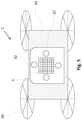
- Fig. 5 shows a schematic illustration of a QKD terminal 1 for quantum communication according to a further embodiment of the invention.
- the QKD terminal 1 is mounted on a drone 65 having four rotors 66.
- Fig. 5 shows the bottom side 66 of the QKD terminal 1.
- the dynamic holographic device 5 is arranged in the center of the bottom surface 5.
- Arranged around the dynamic holographic device 5 are four beacon detectors 42 for even more redundancy and being capable to detect beacon light 43 incident from all directions.
- the four beacon detectors 42 may also be used to discriminate incident beacons having multiple mutually different wavelengths coming from multiple directions.
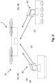
- Fig. 6 shows a schematic illustration of a QKD system 10 for quantum communication according to a further embodiment of the invention.
- the first optical receiver is stationary, and the second optical receiver R2 is mounted on a moving vehicle.
- the QKD terminal 1 is mounted on an unmanned air vehicle.
- Each receivers R1, R2 comprises a beacon aperture 68, from which the beacon light 43 is emitted, and a communication-link aperture 69, from which the input signal 53 is emitted from.
- Fig. 7 shows a schematic illustration of an optical receiver R of a QKD system 10 for quantum communication according to a further embodiment of the invention.
- the optical receiver R shown in Fig. 7 is applicable to the first and second optical receivers R1 and R2 present in the previous embodiments of the QKD systems 10.
- the first receiver R1 is considered here as the optical receiver R receives a receiver input signal 77, which is the output signal 50 of the QKD terminal 1, and the entangled photon 7, both emitted by the QKD terminal 1.
- the receiver input signal 77 may be a classical communication signal.
- the receiver input signal 77 and the entangled photon 7 (or 8) is received by the optical receiver R is first incident on two coarse steering mirrors 70, which are motorized to rotate in two dimensions.
- the receiver input signal 77and the entangled photon 7 then propagate through a beam expander 61 onto a deflection element 41.
- the beam path of the receiver input signal 77 and the entangled photon 7 is then split towards a fiber collimator 74, a position sensitive photodetector 72 and a wavefront sensor 73 by two beam splitters 71.
- separate fiber collimators 74 are provided for the receiver input signal 77 and the entangled photon 7. In a reversed manner as described with relation to Fig.
- the receiver input signal 77 and the entangled photon 7 is processed by the fiber optical circuit 54 comprising the (de-)multiplexer 55, the optical circulator 56, a detector 52 for the receiver input signal 77and a QKD detection unit 75 instead of the entangled photon source 2.
- the QKD detection unit 75 is configured to measure the quantum state of entangled photon 7 and comprises at least one or more photon counters.
- a receiver output signal 78 which becomes the input signal 53 at the QKD terminal 1, is emitted by the light source 49 connected to the optical circulator 56.
- the (de-)multiplexer 55 is configured as a wavelength multiplexer. In further embodiments, the multiplexer 55 may be configured as a spatial mode multiplexer.
- the tilt 44 of the deflecting element is corrected by the receiver controller 76. In this way, the pointing of the incoming receiver input signal 77and the entangled photon 7 is stabilized.
- the signal from the position sensitive photodetector 72 could be used to control both the fast steering mirror 44 and the coarse pointing mirrors 70.
- two position sensitive detectors can be implemented, one with smaller field of view (e.g. a quadrant detector) for controlling the fast steering mirror 44, and another one with larger field of view (e.g. a camera) to control the mirrors 70
- the wavefront sensor 73 is configured to measure the wavefront of the output signal 50.
- the receiver controller 76 is configured to trigger an adaptive optical element (not shown in Fig. 7 ) to manipulate a wavefront of the received entangled photon 7 such that it can be better coupled into the fiber collimator 74 and better detected in the QKD detection unit 75.
- the receiver input signal 77 can be corrected simultaneously.
- the communication channel 51 can be used to analyze the atmospheric turbulences and correspondingly correct the wavefront for both, the communication beams, i.e. for the receiver output signal 78 and receiver input signal 77, and the entangled photon 7 (and 8 at the second receiver R2 respectively). Since this improves the focus of the entangled photon onto the photon counter at the receiver, this aspect leads to a higher key-data rate.
- Fig. 8 shows a schematic illustration of a method for quantum communication according to a further embodiment of the invention.
- the method for quantum communication comprises the steps of generating S1 by an entangled photon source 2, a pair of entangled photons 3.
- the method comprises the step of directing S2 the pair of entangled photons 3 to a dynamic holographic device 5. Additionally, the method comprises a triggering S3, by a controller 6, the dynamic holographic device 5 to redirect a first entangled photon 7 of the pair of entangled photons 3 to a first direction D1 and the second entangled photon 8 of the pair of entangled photons 3 to a second direction D2 different from the first direction D1.
Landscapes
- Engineering & Computer Science (AREA)
- Computer Security & Cryptography (AREA)
- Computer Networks & Wireless Communication (AREA)
- Signal Processing (AREA)
- Physics & Mathematics (AREA)
- Electromagnetism (AREA)
- Theoretical Computer Science (AREA)
- Optical Communication System (AREA)
Abstract
The present invention a QKD terminal for entangled photon Quantum Key Distribution, comprising: a photon source configured to emit a pair of entangled photons on a QKD channel, a dynamic holographic device arranged downstream of the photon source on the QKD channel and configured to receive and redirect the pair of entangled photons; and a controller connected to the holographic element and configured to trigger the holographic element to redirect a first entangled photon of the pair of entangled photons to a first direction and a second entangled photon of the pair of entangled photons to a second direction different from the first direction. The present invention further provides a QKD system and a method for quantum communication.
Description
- The present invention is directed to a QKD terminal, a QKD system and a method for quantum communication.
- Entanglement-based Quantum Key Distribution (QKD) provides secure communication between for example airborne and/or ground vehicles. In such link, a third vehicle, positioned between the two communication partners, hosts an entangled photon source that provides a secret key to communication parties. In a scenario, an airborne vehicle carrying an entangled photon source, can distribute entangled photon pairs between the two ground vehicles establishing a shared encryption key between them.
- A typical approach on airborne or spaceborne platforms hosting an entangled QKD source is to provide separate telescopes for sending each photon of the entangled photon pairs in different directions, towards the two communication parties. For these systems, there is a need to provide an improved terminal.
- According to the invention, this problem is solved by the subject matter of the independent claims.
- According to a first aspect of the invention, a QKD terminal for quantum communication is provided. The QKD terminal comprises: a photon source configured to emit a pair of entangled photons on a QKD channel, a dynamic holographic device arranged downstream of the photon source on the QKD channel and configured to receive and redirect the pair of entangled photons; and a controller connected to the holographic element and configured to trigger the holographic element to redirect a first entangled photon of the pair of entangled photons to a first direction and a second entangled photon of the pair of entangled photons to a second direction different from the first direction.
- According to a second aspect of the invention, a QKD system for quantum communication is provided. The QKD system comprises an inventive QKD terminal, a first optical receiver and a second optical receiver, wherein the controller is configured to trigger the holographic element to redirect the first entangled photon to the first optical receiver and the second entangled photon to the second optical receiver.
- According to a third aspect of the invention, a method for quantum communication is provided. The method comprises generating, by an entangled photon source, a pair of entangled photons; directing the pair of entangled photons to a dynamic holographic device; and triggering, by a controller, the dynamic holographic device to redirect a first entangled photon of the pair of entangled photons to a first direction and the second entangled photon of the pair of entangled photons to a second direction different from the first direction.
- A fundamental concept of the invention is to send the pair of entangled photons through a single aperture toward two different receivers. For this, a steering element is required that is capable to split the pair of entangled photons and deflect these in two different directions. This steering element suitable for this function has been identified as the dynamic holographic device.
- As within this invention, the dynamic holographic device should be understood in the following way. The feature of being dynamic enables the dynamic holographic device to direct the entangled photons onto moving receivers such as moving particles. For this, the dynamic holographic device applies a phase shift across the incident wavefront according to the direction such that the entangled photons are deflected. The dynamic holographic device also has the capability of shaping both the amplitude and the phase of the electric field. This is beneficial for minimizing side-lobes and in general for shaping the wavefronts of the two output beams. This may be performed for a reflective type dynamic holographic device by modifying, e.g. locally raising or lowering, a deflecting surface of the dynamic holographic device, or for a transmissive dynamic type holographic element by changing a refractive index of the internal medium the entangled photon is propagating. In both cases, a certain pitch- and/or grating-like modification similar to a phased array is applied to the surface or the internal medium.
- A particular advantage in the solution according to an aspect of the invention is the compactness of the dynamic holographic device that basically substitutes and eliminates an entire aperture including a telescope. Furthermore, since the entangled photons are steered in a non-mechanical way, the present invention renders a mechanical coarse steering system obsolete, which makes the terminal more robust to environmental factors, such as wind or vibrations.
- The dynamic holographic device is positioned downstream of the entangled photon source, which emits a stream of entangled photons downstream the QKD channel to the holographic device positioned. As within this invention, the QKD channel should be understood as the optical path of the entangled photons, which starts with the generation and emission of the pair of photons in the entangled photon source at the QKD terminal. Therefore, all further devices arranged on the QKD channel are arranged downstream the entangled photon source.
- Advantageous embodiments and further developments emerge from the description with reference to the figures.
- According to some further aspects of the QKD terminal according to the invention, the dynamic holographic device is configured as a tunable meta surface, a liquid crystal spatial light modulator, and/or a digital hologram. These devices are particularly well developed and suitable for functioning as the dynamic holographic device. Further devices forming the dynamic holographic device by a similar principle are thinkable.
- According to some further aspects of the QKD terminal according to the invention, the dynamic holographic device comprises a first meta surface and a second meta surface downstream the first meta surface in the QKD channel, wherein the first meta surface is configured as a grating for splitting an incident beam into a first beam and a second beam, wherein the second meta surface is configured as a beam steering element, wherein the controller is configured to trigger the second meta surface to redirect the first entangled photon to the first direction and the second entangled photon to the second direction. Using a sequence of two or even more flat optics, the functions of splitting the pair of entangled photons and steering the entangled photons is separated. In this way, the first and second meta surface may be selected according to the optimum suitability for the specific functions. The dynamic holographic device may thus be implemented in a simpler way.
- According to some further aspects of the QKD terminal according to the invention, the first meta surface and the second meta surface are mounted on a rotational stage configured to rotate about an azimuthal direction. The azimuthal direction is the direction around the orthogonal or normal direction from a surface of the dynamic holographic device. The second meta surface is configured as a one-dimensional beam steering element. Thus, a degree of freedom of the beam steering has been removed, so that the first meta surface and the second meta surface only need to operate along a single axis.
- According to some further aspects of the QKD terminal according to the invention, the first meta surface and the second meta surface are formed on a substrate. The substrate is configured as a base layer of the respective meta surface. The controller is configured to trigger the first meta surface and/or the second meta surface to deflect the first entangled photon and the second entangled photon by stretching the substrate. This is a simple way to tune the meta surface in order to split and/or steer the entangled photons.
- According to some further aspects of the QKD terminal according to the invention, the second meta surface is formed on a thermo-optical substrate. The controller is configured to deflect the first entangled photon and the second entangled photon by applying a temperature to the thermo-optical substrate. This could be performed in case the substrate has a temperature-dependent refractive index. This aspect thus provides another simple way to tune the meta surface in order to split and/or steer the entangled photons.
- According to some further aspects of the QKD terminal according to the invention, the QKD terminal further comprises a pointing system comprising a deflecting element arranged downstream the entangled photon source and configured to deflect the pair of entangled photons, and a beacon detector configured to sense an angle of arrival of a beacon light incident to the QKD terminal, wherein the controller is configured to control a tilt of the deflecting element based on the sensed angle of arrival of the beacon light. By analyzing the beacon light coming from the receiver, information about the direction of the receiver can be obtained. By suitably addressing the tilt of the deflecting element according to this information, the pointing of the entangled photons in the QKD channel toward a receiver is stabilized.
- According to some further aspects of the QKD terminal according to the invention, the beacon detector comprises a first photodetector configured to sense a first beacon light having a first wavelength, and a second detector configured to sense a second beacon light having a second wavelength. In this way, two beacons having two different wavelengths and coming from different directions can be analyzed. The pointing of the entangled photons in the QKD channel can be stabilized by correspondingly addressing the tilt of the deflecting element.
- According to some further aspects of the QKD terminal according to the invention, wherein the entangled photon source is implemented on an integrated photonic circuit. In this way, a very compact device particularly suitable for an airborne or spaceborne vehicle can be realized.
- According to some further aspects of the QKD terminal according to the invention, the QKD terminal further comprises a light source arranged and configured to emit an output signal on a communication channel, and a detector arranged and configured to receive an input signal of the optical communication channel, wherein the dynamic holographic device is arranged on the communication channel downstream the light source and the detector. In this way, the QKD terminal can also function as an intermediate communication node, to extend an optical communication network between different optical receivers.
- According to some further aspects of the QKD terminal according to the invention, the QKD terminal further comprises a fiber optical circuit arranged and configured to couple the pair of entangled photons, the input signal and output signal into the fiber optical circuit, wherein the fiber optical circuit comprises a multiplexer configured to combine the output signal with the entangled photons. In this way, the terminal can be made more compact and robust against vibrations or other environmental influences.
- According to some further aspects of the QKD terminal according to the invention, the fiber optical circuit comprises an optical circulator arranged and configured to receive the input signal and the output signal and direct the input signal to the detector and the output signal to the multiplexer. The optical circulator is a fiber device that here has the benefit to allow signals propagating in opposite directions through the same fiber. Therefore, the optical circulator improves the compactness of the device.
- According to some further aspects of the QKD system according to the invention, at least one of the first optical receiver and the second optical receiver is mounted on a moving vehicle, and/or wherein the QKD terminal is mounted on an unmanned air vehicle or a satellite. This aspect represents the versatile application of the present invention.
- According to some further aspects of the QKD system according to the invention the first optical receiver and/or second optical receiver comprises a wavefront sensor configured to measure the wavefront of the communication beam, and an adaptive optical element configured to manipulate a wavefront of the received entangled photon, wherein the receiver control circuit is configured to correct the wavefront of the entangled photons by controlling the adaptive optical element. In this way, the communication channel can be used to analyze the atmospheric turbulences and correspondingly correct the wavefront for both, the communication beams and the entangled photon. Since this improves the focus of the entangled photon onto the photon counter at the receiver, this aspect results in a higher key-rate.
- The present invention is explained in more detail below with reference to the embodiments shown in the schematic figures:
- Fig. 1
- a schematic illustration of a QKD terminal for quantum communication according to an embodiment of the invention;
- Fig. 2
- a schematic illustration of a QKD system for quantum communication according to an embodiment of the invention;
- Fig. 3
- a schematic illustration of a dynamic holographic device for quantum communication according to a further embodiment of the invention;
- Fig. 4
- a schematic illustration of a QKD system for quantum communication according to a further embodiment of the invention;
- Fig. 5
- a schematic illustration of a QKD terminal for quantum communication according to a further embodiment of the invention;
- Fig. 6
- a schematic illustration of a QKD system for quantum communication according to a further embodiment of the invention;
- Fig. 7
- a schematic illustration of an optical receiver of a QKD system for quantum communication according to a further embodiment of the invention; and
- Fig. 8
- a schematic illustration of a method for quantum communication according to a further embodiment of the invention;
- In the figures of the drawing, elements, features and components which are identical, functionally identical and of identical action are denoted in each case by the same reference designations unless stated otherwise.
-
Fig. 1 shows a schematic illustration of aQKD terminal 1 for quantum communication according to an embodiment of the invention. - The
QKD terminal 1 for quantum communication shown inFig. 1 comprises aphoton source 2 configured to emit a pair ofentangled photons 3 on aQKD channel 4. Suchentangled photon sources 3 may emit entangled photons of the same wavelength, e.g. 1550 nm, or different wavelengths. The pair ofentangled photons 3 are emitted on theQKD channel 4 on the same optical axis A, i.e. in the same direction. It is understood that theentangled photon source 2 is typically configured to emit a stream of entangled photon having a certain repetition rate, e.g. between 100 Hz and 100 Mhz. - The
QKD terminal 1 further comprises a dynamicholographic device 5 arranged downstream of thephoton source 2 on theQKD channel 4 and configured to receive and redirect the pair ofentangled photons 3. In this embodiment, the dynamicholographic device 5 is configured as a tunable meta surface. In further embodiments, the dynamicholographic device 5 is configured as a liquid crystal spatial light modulator and a digital hologram. In this embodiment, the dynamicholographic device 5 as the final optical element downstream theQKD channel 4 inside theQKD terminal 1. In further embodiment, a window, a telescope or other optical elements may be arranged downstream the dynamicholographic device 5 inside theQKD terminal 1. - The
QKD terminal 1 further comprises acontroller 6, which is connected to theholographic element 5. Thecontroller 6 is configured to trigger theholographic element 5 to redirect a firstentangled photon 7 of the pair ofentangled photons 3 to a first direction D1 and a secondentangled photon 8 of the pair ofentangled photons 3 to a second direction D2 different from the first direction D1. The pair ofphotons 3 thus is split into the firstentangled photon 7 propagating in the first direction D1 and the secondentangled photon 8 propagating in the second direction D2. The dynamicholographic device 5 thus deflects the firstentangled photon 7 by a first deflection angle α1 and the secondentangled photon 8 by a deflection angle α2. The first and second deflection angles α1, α2 may be of similar with respect to the original optical axis A and respective first direction D1 and second direction D2 or they may be different. - In further embodiments, the
controller 6 is also connected to theentangled photon source 2 and configured to control parameter, such as e.g. the repetition rate. -
Fig. 2 shows a schematic illustration of aQKD system 10 for quantum communication according to an embodiment of the invention. - The
QKD system 10 for quantum communication shown inFig. 2 comprises aQKD terminal 1 according to the previousFig. 1 or any other embodiment of the invention. A first optical receiver R1 and a second optical receiver R2 are arranged distant from theQKD terminal 1. Thecontroller 6 is configured to trigger theholographic element 5 to redirect the firstentangled photon 7 to the first optical receiver R1 and the secondentangled photon 8 to the second optical receiver R2. The receivers R1 and R2 receive the respective first and secondentangled photons Fig. 2 ). -
Fig. 3 shows a schematic illustration of a dynamic holographic 5 device according to an embodiment of the invention; - The dynamic
holographic device 5 shown inFig . 3 represents a particular embodiment of the dynamicholographic device 5 and can be applied to theQKD terminal 1 of the embodiments of this invention. The dynamicholographic device 5 comprises a firstmeta surface 30 and a secondmeta surface 31 downstream the firstmeta surface 30 in theQKD channel 4. The firstmeta surface 30 is configured as a grating for splitting anincident beam 32 into afirst beam 33 and asecond beam 34, wherein the secondmeta surface 31 is configured as a beam steering element. Thecontroller 6 is configured to trigger thesecond meta 31 surface to redirect the firstentangled photon 7 to the first direction D1 and the secondentangled photon 8 to the second direction D2. - In this embodiment, the first
meta surface 30 and the secondmeta surface 31 are mounted on an optionalrotational stage 35, which is configured to rotate about an azimuthal direction ϕ. Due to this rotation, one degree of freedom for steering theentangled photons meta surface 31 is configured as a one-dimensional beam steering element, since this is sufficient. It is understood that in the setup shown inFig. 3 , that the first and second directions D1, D2 point out of the drawing plane, which is not shown for simplicity of the figure. - Furthermore, the first
meta surface 30 and the secondmeta surface 31 are formed onrespective substrates controller 6 is configured to trigger the firstmeta surface 30 to deflect the firstentangled photon 7 by mechanical stretching the substrate. This can be performed using actuators (not shown here) that pull or push thesubstrate 36. Any suitable, e.g. piezo-based, mechanism or devices may be used for this function. - In this embodiment, the second
meta surface 32 comprises a thermo-optical substrate 37. For the second meta surface, thecontroller 6 is configured to deflect the firstentangled photon 7 and the secondentangled photon 8 by applying a temperature to thesubstrate 37. -
Fig. 4 shows a schematic illustration of aQKD system 10 for quantum communication according to a further embodiment of the invention. - The
QKD terminal 1 of theQKD system 10 shown inFig. 4 is based on theQKD terminal 1 inFig. 1 , however, having additional elements and functions. - The
QKD terminal 1 for quantum communication shown inFig. 4 comprises aphoton source 2 configured to emit a pair ofentangled photons 3 on aQKD channel 4. The pair ofentangled photons 3 are emitted on theQKD channel 4 in the same direction. - The
QKD terminal 1 further comprises a dynamicholographic device 5 arranged downstream of thephoton source 2 on theQKD channel 4 and configured to receive and redirect the pair ofentangled photons 3. In this embodiment, the dynamicholographic device 5 is configured as a tunable meta surface. In further embodiments, the dynamicholographic device 5 is configured as a liquid crystal spatial light modulator and a digital hologram. - The
QKD terminal 1 further comprises acontroller 6, which is connected to theholographic element 5. Thecontroller 6 is configured to trigger theholographic element 5 to redirect a firstentangled photon 7 of the pair ofentangled photons 3 to a first direction D1 and a secondentangled photon 8 of the pair ofentangled photons 3 to a second direction D2 different from the first direction D1. The pair ofphotons 3 thus is split into the firstentangled photon 7 propagating in the first direction D1 and the secondentangled photon 8 propagating in the second direction D2. - In this embodiment, the pair of
entangled photons 3 are coupled into a fiberoptical circuit 54. Fibers used for the fiberoptical circuit 54 are single mode fibers. In further embodiments, few-modes or multi-mode fibers are applied. Theentangled photons 3 then pass amultiplexer 55, wherein the entangled photons are combined with anoutput signal 50. Themultiplexer 55 is configured as a wavelength multiplexer. In further embodiments, themultiplexer 55 may be configured as a spatial mode multiplexer. Theoutput signal 50 is emitted by alight source 49 upstream themultiplexer 55. The pair ofentangled photons 3 further passes through thefiber optic circuit 54 and exits the fiberoptical circuit 54 at thefiber collimator 57, from where it propagates to alens 58 to propagate along the optical axis A in free-space. It then passesrelay lenses 59 and incidice on a deflectingelement 41, which is configured as a fast steering mirror. Therelay lenses 59 have the function to map a pupil on the deflecting element. - The deflecting
element 41 is part of apointing system 40 comprising the deflectingelement 41 arranged downstream theentangled photon source 2 and configured to deflect the pair ofentangled photons 3. The pair ofentangled photons 3 then passes adichroic filter 60, a lens fordivergence adjustment 61 and abeam expander 62 to be incident on the dynamicholographic device 5. There, the pair ofentangled photons 3 is split into the firstentangled photon 7 and the secondentangled photon 8, which are redirected into the first direction D1 and the second direction D2 towards respective receivers R1 and R2. - The
pointing system 40 further comprises, abeacon detector 42 configured to sense an angle of arrival θ of a beacon light incident 43 incident on theQKD terminal 1. For this, a wide-angle lens 62 having a high NA, e.g. >1, is arranged as a receiver aperture. In further embodiments, the wide-angle lens 62 is configured as a fish-eye lens. The beacon light then propagates onto adichroic beam splitter 63, where first beacon light 46 can be separated from a second beacon light 48 having different wavelength than the first beacon light 46. Each of the beacon light 46 and 48 propagates through a focusinglens 64, which effectively converts an angle into a displacement in the focal plane of the focusinglens 64. In the focal plane, afirst photodetector 45 and asecond photodetector 47 are arranged. Both first andsecond photodetectors first photodetector 45 is thus configured to sense an angle of arrival θ the first beacon light 46 having the first wavelength, and thesecond detector 47 is configured to sense an angle of arrival θ of a second beacon light 48 having a second wavelength. - The position of the intensity spot on the first and
second photodetectors controller 6. Thecontroller 6 is configured to control atilt 44 of the deflectingelement 41 based on the position of the intensity spot on thephotodetectors - The
light source 49 is arranged and configured to emit theoutput signal 50 on acommunication channel 51. A correspondingdetector 52 is arranged and configured to receive aninput signal 53 propagating on theoptical communication channel 51. The fiberoptical circuit 54 comprises anoptical circulator 56 arranged and configured to receive theinput signal 53 and theoutput signal 50 and direct theinput signal 53 to thedetector 52 and theoutput signal 50 to themultiplexer 55. - Both the
input signal 53 and theoutput signal 50 couple/decouple from/to the fiberoptical circuit 54 through thefiber collimator 57 to/from where it propagates along the optical axis A to the dynamicholographic device 5. The dynamicholographic device 5 deflects theinput signal 53 andoutput signal 50 in a similar way as theentangled photons - In
Fig. 4 , twobeacon detectors 42 with respective components are shown. The number of twobeacon detectors 42 instead of one has been implemented for better redundancy and may also be used in case more than two beacon light 43 having mutually different wavelengths are incident on theQKD terminal 1. A tilt of the deflectingelement 41 as fine steering mirror is thus based on an average of the measured positions on both thefirst photodetectors 45 or thesecond photodetectors 47. - In this embodiment, the
entangled photon source 2 is implemented on an integrated photonic circuit. In further embodiments, the entire fiberoptical circuit 54 is implemented on an integrated photonic circuit. In particular, the fiberoptical circuit 54 can also implemented as an photonics integrated circuit. Furthermore, theentangled photon source 2 and theoptical circuit 54 can parts of the same integrated circuit. -
Fig. 5 shows a schematic illustration of aQKD terminal 1 for quantum communication according to a further embodiment of the invention. - In this embodiment, the
QKD terminal 1 is mounted on adrone 65 having fourrotors 66.Fig. 5 shows thebottom side 66 of theQKD terminal 1. The dynamicholographic device 5 is arranged in the center of thebottom surface 5. Arranged around the dynamicholographic device 5 are fourbeacon detectors 42 for even more redundancy and being capable to detect beacon light 43 incident from all directions. The fourbeacon detectors 42 may also be used to discriminate incident beacons having multiple mutually different wavelengths coming from multiple directions. -
Fig. 6 shows a schematic illustration of aQKD system 10 for quantum communication according to a further embodiment of the invention. - In this embodiment of the
QKD system 10, the first optical receiver is stationary, and the second optical receiver R2 is mounted on a moving vehicle. TheQKD terminal 1 is mounted on an unmanned air vehicle. Each receivers R1, R2 comprises abeacon aperture 68, from which the beacon light 43 is emitted, and a communication-link aperture 69, from which theinput signal 53 is emitted from. -
Fig. 7 shows a schematic illustration of an optical receiver R of aQKD system 10 for quantum communication according to a further embodiment of the invention. - The optical receiver R shown in
Fig. 7 is applicable to the first and second optical receivers R1 and R2 present in the previous embodiments of theQKD systems 10. Exemplary, the first receiver R1 is considered here as the optical receiver R receives a receiver input signal 77, which is theoutput signal 50 of theQKD terminal 1, and theentangled photon 7, both emitted by theQKD terminal 1. The receiver input signal 77 may be a classical communication signal. - The receiver input signal 77 and the entangled photon 7 (or 8) is received by the optical receiver R is first incident on two coarse steering mirrors 70, which are motorized to rotate in two dimensions. The receiver input signal 77and the
entangled photon 7 then propagate through abeam expander 61 onto adeflection element 41. The beam path of the receiver input signal 77 and theentangled photon 7 is then split towards afiber collimator 74, a positionsensitive photodetector 72 and awavefront sensor 73 by twobeam splitters 71. In further embodiment,separate fiber collimators 74 are provided for the receiver input signal 77 and theentangled photon 7. In a reversed manner as described with relation toFig. 4 the receiver input signal 77 and theentangled photon 7 is processed by the fiberoptical circuit 54 comprising the (de-)multiplexer 55, theoptical circulator 56, adetector 52 for the receiver input signal 77and aQKD detection unit 75 instead of theentangled photon source 2. TheQKD detection unit 75 is configured to measure the quantum state ofentangled photon 7 and comprises at least one or more photon counters. Areceiver output signal 78, which becomes theinput signal 53 at theQKD terminal 1, is emitted by thelight source 49 connected to theoptical circulator 56. The (de-)multiplexer 55 is configured as a wavelength multiplexer. In further embodiments, themultiplexer 55 may be configured as a spatial mode multiplexer. - Based on the measured position on the
photodetector 72, thetilt 44 of the deflecting element is corrected by thereceiver controller 76. In this way, the pointing of the incoming receiver input signal 77and theentangled photon 7 is stabilized. Furthermore, the signal from the positionsensitive photodetector 72 could be used to control both thefast steering mirror 44 and the coarse pointing mirrors 70. Alternatively, two position sensitive detectors can be implemented, one with smaller field of view (e.g. a quadrant detector) for controlling thefast steering mirror 44, and another one with larger field of view (e.g. a camera) to control themirrors 70 - The
wavefront sensor 73 is configured to measure the wavefront of theoutput signal 50. Thereceiver controller 76 is configured to trigger an adaptive optical element (not shown inFig. 7 ) to manipulate a wavefront of the receivedentangled photon 7 such that it can be better coupled into thefiber collimator 74 and better detected in theQKD detection unit 75. At the same time, the receiver input signal 77 can be corrected simultaneously. In this way, thecommunication channel 51 can be used to analyze the atmospheric turbulences and correspondingly correct the wavefront for both, the communication beams, i.e. for thereceiver output signal 78 and receiver input signal 77, and the entangled photon 7 (and 8 at the second receiver R2 respectively). Since this improves the focus of the entangled photon onto the photon counter at the receiver, this aspect leads to a higher key-data rate. -
Fig. 8 shows a schematic illustration of a method for quantum communication according to a further embodiment of the invention. - The method for quantum communication comprises the steps of generating S1 by an
entangled photon source 2, a pair ofentangled photons 3. The method comprises the step of directing S2 the pair ofentangled photons 3 to a dynamicholographic device 5. Additionally, the method comprises a triggering S3, by acontroller 6, the dynamicholographic device 5 to redirect a firstentangled photon 7 of the pair ofentangled photons 3 to a first direction D1 and the secondentangled photon 8 of the pair ofentangled photons 3 to a second direction D2 different from the first direction D1. - In the detailed description above, various features have been combined in one or more examples in order to improve the rigorousness of the illustration. However, it should be clear in this case that the above description is of merely illustrative but in no way restrictive nature. It serves to cover all alternatives, modifications and equivalents of the various features and exemplary embodiments. Many other examples will be immediately and directly clear to a person skilled in the art on the basis of his knowledge in the art in consideration of the above description.
- The exemplary embodiments have been chosen and described in order to be able to present the principles underlying the invention and their application possibilities in practice in the best possible way. As a result, those skilled in the art can optimally modify and utilize the invention and its various exemplary embodiments with regard to the intended purpose of use. In the claims and the description, the terms "including" and "having" are used as neutral linguistic concepts for the corresponding terms "comprising". Furthermore, use of the terms "a", "an" and "one" shall not in principle exclude the plurality of features and components described in this way.
- While at least one exemplary embodiment of the present invention(s) is disclosed herein, it should be understood that modifications, substitutions and alternatives may be apparent to one of ordinary skill in the art and can be made without departing from the scope of this disclosure. This disclosure is intended to cover any adaptations or variations of the exemplary embodiment(s). In addition, in this disclosure, the terms "comprise" or "comprising" do not exclude other elements or steps, the terms "a" or "one" do not exclude a plural number, and the term "or" means either or both. Furthermore, characteristics or steps which have been described may also be used in combination with other characteristics or steps and in any order unless the disclosure or context suggests otherwise. This disclosure hereby incorporates by reference the complete disclosure of any patent or application from which it claims benefit or priority.
-
- 1
- QKD terminal
- 2
- entangled photon source
- 3
- pair of entangled photons
- 4
- QKD channel
- 5
- dynamic holographic device
- 6
- controller
- 7
- first entangled pulse
- 8
- second entangled pulse
- 10
- QKD system
- 30
- first meta surface
- 31
- second meta surface
- 32
- incident beam
- 33
- first beam
- 34
- second beam
- 35
- rotational stage
- 36
- substrate
- 37
- thermo-optical substrate
- 40
- pointing system
- 41
- deflecting element
- 42
- beacon detector
- 43
- beacon light
- 44
- tilt of the deflecting element
- 45
- first photodetector
- 46
- first beacon light
- 47
- second photodetector
- 48
- second beacon light
- 49
- light source
- 50
- output signal
- 51
- communication channel
- 52
- detector
- 53
- input signal
- 54
- fiber optical circuit
- 55
- multiplexer
- 56
- optical circulator
- 57
- fiber collimator
- 58
- lens
- 59
- relay lenses
- 60
- dichroic filter
- 61
- beam expander
- 62
- wide angle lens
- 63
- dichroic beam splitter
- 64
- focussing lens
- 65
- drone
- 66
- rotor
- 67
- bottom side of the QKD terminal
- 68
- beacon aperture
- 69
- communication-link aperture
- 70
- coarse steering mirrors
- 71
- beam splitter
- 72
- photodetector
- 73
- wavefront sensor
- 74
- fiber collimator
- 75
- QKD detection unit
- 76
- receiver controller
- 77
- receiver input signal
- 78
- receiver output signal
- A
- optical axis
- D1
- first direction
- D2
- second direction
- R, R1, R2
- receiver
- S1-S3
- method steps
- ϕ
- rotational angle
- θ
- angle of arrival of the beacon light
Claims (15)
- QKD terminal (1) for quantum communication, comprising:a photon source (2) configured to emit a pair of entangled photons (3) on a QKD channel (4),a dynamic holographic device (5) arranged downstream of the photon source (2) on the QKD channel (4) and configured to receive and redirect the pair of entangled photons (3); anda controller (6) connected to the holographic element (5) and configured to trigger the holographic element (5) to redirect a first entangled photon (7) of the pair of entangled photons (3) to a first direction (D1) and a second entangled photon (8) of the pair of entangled photons (3) to a second direction (D2) different from the first direction (D1).
- QKD terminal (1) according to claim 1, wherein the dynamic holographic device (5) is configured as a tunable meta surface, a liquid crystal spatial light modulator, and/or a digital hologram.
- QKD terminal (1) according to claim 1 or 2, wherein the dynamic holographic device (5) comprises a first meta surface (30) and a second meta surface (31) downstream the first meta surface (31) in the QKD channel (4), wherein the first meta surface (30) is configured as a grating for splitting an incident beam (32) into a first beam (33) and a second beam (34), wherein the second meta surface (31) is configured as a beam steering element, wherein the controller (6) is configured to trigger the second meta (31) surface to redirect the first entangled photon (7) to the first direction (D1) and the second entangled photon (8) to the second direction (D2).
- QKD terminal (1) according (1) to claim 3, wherein the first meta surface (30) and the second meta surface (31) are mounted on a rotational stage (35) configured to rotate about an azimuthal direction (ϕ), and wherein the second meta surface (31) is configured as a one-dimensional beam steering element.
- QKD terminal (1) according to claim 3 or 4, wherein the first meta surface (30) and the second meta surface (31) are formed on a respective substrate (36), wherein the controller (6) is configured to trigger the first meta surface (30) and/or the second meta surface (31) to deflect the first entangled photon (7) and the second entangled photon (8) by stretching the respective substrate.
- QKD terminal (1) according to claim 3 or 4, wherein the second meta surface (32) is formed on a thermo-optical substrate (37), wherein the controller (6) is configured to deflect the first entangled photon (7) and the second entangled photon (8) by applying a temperature to the thermo-optical substrate (37).
- QKD terminal (1) according to any of the precedent claims, further comprising a pointing system (40) comprising a deflecting element (41) arranged downstream the entangled photon source (2) and configured to deflect the pair of entangled photons (3), and a beacon detector (42) configured to sense an angle of arrival (θ) of a beacon light incident (43) to the QKD terminal (1), wherein the controller (6) is configured to control a tilt (44) of the deflecting element (41) based on the sensed angle of arrival (θ)of the beacon light.
- QKD terminal (1) according to claim 7, wherein the beacon detector (42) comprises a first photodetector (45) configured to sense a first beacon light (46) having a first wavelength, and a second detector (47) configured to sense a second beacon light (48) having a second wavelength.
- QKD terminal (1) according to any of the preceding claims, wherein the entangled photon source (2) is implemented on an integrated photonic circuit.
- QKD terminal (1) according to any of the preceding claims, further comprising a light source (49) arranged and configured to emit an output signal (50) on a communication channel (51), and a detector (52) arranged and configured to receive an input signal (53) of the optical communication (51) channel, wherein the dynamic holographic device (5) is arranged on the communication channel (51) downstream the light source (49) and the detector (54).
- QKD terminal (1) according to claim 10, further comprising a fiber optical circuit (54) arranged and configured to couple the pair of entangled photons (3), the input signal (53) and the output signal (50) into the fiber optical circuit (54), wherein the fiber optical circuit (54) comprises a multiplexer (55) configured to combine the output signal (50) with the entangled photons (3).
- QKD terminal (1) according to claim 11, wherein the fiber optical circuit (54) comprises an optical circulator (56) arranged and configured to receive the input signal (53) and the output signal (50) and direct the input signal (53) to the detector (52) and the output signal (50) to the multiplexer (55).
- QKD system (10) for quantum communication, comprising a QKD terminal (1) according to any of the preceding claims, a first optical receiver (R1) and a second optical receiver (R2), wherein the controller (6) is configured to trigger the holographic element (5) to redirect the first entangled photon (7) to the first optical receiver (R1) and the second entangled photon (8) to the second optical receiver (R2).
- QKD system (10) according to claim 13, wherein at least one of the first optical receiver (R1) and the second optical receiver (R2) is mounted on a moving vehicle, and/or wherein the QKD terminal (1) is mounted on an unmanned air vehicle or a satellite.
- Method for quantum communication, comprising:generating, by an entangled photon source (2), a pair of entangled photons (3);directing the pair of entangled photons (3) to a dynamic holographic device (5); andtriggering, by a controller (6), the dynamic holographic device (5) to redirect a first entangled photon (7) of the pair of entangled photons (3) to a first direction (D1) and the second entangled photon (8) of the pair of entangled photons (3) to a second direction (D2) different from the first direction (D1).
Priority Applications (3)
| Application Number | Priority Date | Filing Date | Title |
|---|---|---|---|
| EP22214399.2A EP4387159A1 (en) | 2022-12-16 | 2022-12-16 | Qkd terminal, qkd system and method for quantum communication |
| US18/529,304 US12615139B2 (en) | 2022-12-16 | 2023-12-05 | QKD terminal, QKD system and method for quantum communication |
| CN202311716471.8A CN118214544A (en) | 2022-12-16 | 2023-12-14 | Quantum key distribution terminal, system and method for quantum communication |
Applications Claiming Priority (1)
| Application Number | Priority Date | Filing Date | Title |
|---|---|---|---|
| EP22214399.2A EP4387159A1 (en) | 2022-12-16 | 2022-12-16 | Qkd terminal, qkd system and method for quantum communication |
Publications (1)
| Publication Number | Publication Date |
|---|---|
| EP4387159A1 true EP4387159A1 (en) | 2024-06-19 |
Family
ID=84537938
Family Applications (1)
| Application Number | Title | Priority Date | Filing Date |
|---|---|---|---|
| EP22214399.2A Pending EP4387159A1 (en) | 2022-12-16 | 2022-12-16 | Qkd terminal, qkd system and method for quantum communication |
Country Status (3)
| Country | Link |
|---|---|
| US (1) | US12615139B2 (en) |
| EP (1) | EP4387159A1 (en) |
| CN (1) | CN118214544A (en) |
Families Citing this family (1)
| Publication number | Priority date | Publication date | Assignee | Title |
|---|---|---|---|---|
| CN121308846B (en) * | 2025-12-09 | 2026-02-13 | 武汉量子技术研究院 | Satellite quantum communication system and method based on hour-level quantum storage |
Citations (1)
| Publication number | Priority date | Publication date | Assignee | Title |
|---|---|---|---|---|
| EP4002723A1 (en) * | 2020-11-19 | 2022-05-25 | Fraunhofer-Gesellschaft zur Förderung der angewandten Forschung e.V. | Optical free-space communication |
Family Cites Families (8)
| Publication number | Priority date | Publication date | Assignee | Title |
|---|---|---|---|---|
| US6897434B1 (en) * | 2002-02-28 | 2005-05-24 | Northwestern University | All-fiber photon-pair source for quantum communications |
| US8983303B2 (en) * | 2004-08-04 | 2015-03-17 | The United States Of America As Represented By The Secretary Of The Army | Quantum based information transfer system and method |
| US8717666B2 (en) * | 2004-09-22 | 2014-05-06 | Quant-Viet Nguyen | Compact solid state entangled photon source |
| US9374376B2 (en) * | 2013-02-27 | 2016-06-21 | The Boeing Company | Anti-hacking system for quantum communication |
| US10891555B2 (en) * | 2018-08-07 | 2021-01-12 | Nxgen Partners Ip, Llc | Universal quantum computer, communication, QKD security and quantum networks using OAM Qu-dits with digital light processing |
| US11418330B2 (en) * | 2019-10-21 | 2022-08-16 | Eagle Technology, Llc | Quantum communication system that switches between quantum key distribution (QKD) protocols and associated methods |
| US11170318B2 (en) * | 2019-10-31 | 2021-11-09 | Nxgen Partners Ip, Llc | Multi-photon, multi-dimensional hyper-entanglement using higher-order radix qudits with applications to quantum computing, QKD and quantum teleportation |
| FR3125658B1 (en) * | 2021-07-22 | 2023-07-21 | Marbeuf Conseil Et Rech | Quantum communication system by entangled photons |
-
2022
- 2022-12-16 EP EP22214399.2A patent/EP4387159A1/en active Pending
-
2023
- 2023-12-05 US US18/529,304 patent/US12615139B2/en active Active
- 2023-12-14 CN CN202311716471.8A patent/CN118214544A/en active Pending
Patent Citations (1)
| Publication number | Priority date | Publication date | Assignee | Title |
|---|---|---|---|---|
| EP4002723A1 (en) * | 2020-11-19 | 2022-05-25 | Fraunhofer-Gesellschaft zur Förderung der angewandten Forschung e.V. | Optical free-space communication |
Non-Patent Citations (1)
| Title |
|---|
| XIAOYAN HUANG ET AL: "Metasurface Holographic Optical Traps for Ultracold Atoms", ARXIV.ORG, CORNELL UNIVERSITY LIBRARY, 201 OLIN LIBRARY CORNELL UNIVERSITY ITHACA, NY 14853, 14 October 2022 (2022-10-14), XP091343781 * |
Also Published As
| Publication number | Publication date |
|---|---|
| US12615139B2 (en) | 2026-04-28 |
| US20240204994A1 (en) | 2024-06-20 |
| CN118214544A (en) | 2024-06-18 |
Similar Documents
| Publication | Publication Date | Title |
|---|---|---|
| US6668108B1 (en) | Optical cross-connect switch with integrated optical signal tap | |
| US7177496B1 (en) | Optical spectral power monitors employing time-division-multiplexing detection schemes | |
| JP4523058B2 (en) | Optimized reconfigurable optical add-drop multiplexer architecture with MEMS-based attenuation or power management | |
| EP3870996B1 (en) | Lidar system with fiber tip reimaging | |
| US6507685B1 (en) | Method and apparatus for servo-based spectral array alignment in optical systems | |
| US7756368B2 (en) | Flex spectrum WSS | |
| CN103246015B (en) | multicast optical switch | |
| US6816640B2 (en) | Optical add drop multiplexer | |
| US6707594B2 (en) | Method and device for switching wavelength division multiplexed optical signals using two-dimensional micro-electromechanical mirrors | |
| US20020081070A1 (en) | Micromirror wavelength equalizer | |
| US11515941B2 (en) | Free space optical communication terminal with dispersive optical component | |
| KR20040010780A (en) | Atmospheric optical data transmission system | |
| EP0977070B1 (en) | Telescope with shared optical path for an optical communication terminal | |
| US7362930B2 (en) | Reduction of MEMS mirror edge diffraction in a wavelength selective switch using servo-based rotation about multiple non-orthogonal axes | |
| US6671428B1 (en) | Wavelength selective optical cross switch and optical add/drop multiplexer using volume phase grating and array of micro electro mechanical mirrors | |
| US6600849B2 (en) | Control system for optical cross-connect switches | |
| US20080056723A1 (en) | Multiple access free space laser communication method and apparatus | |
| US6760501B2 (en) | Device for imposing a field tilt for approximating the inherent field curvature of a focusing element in a free space optical device | |
| US12615139B2 (en) | QKD terminal, QKD system and method for quantum communication | |
| CN103201667A (en) | Optical device | |
| JP4714175B2 (en) | Mirror device and optical device | |
| WO2014061103A1 (en) | Optical path control device | |
| US6906838B2 (en) | Systems and methods for routing optical beams along optical paths using steerable mirrors | |
| KR100805969B1 (en) | Optical add drop multiplexer | |
| RU2699055C1 (en) | System for simultaneous control of several laser beams by means of a fixed liquid crystal matrix |
Legal Events
| Date | Code | Title | Description |
|---|---|---|---|
| PUAI | Public reference made under article 153(3) epc to a published international application that has entered the european phase |
Free format text: ORIGINAL CODE: 0009012 |
|
| STAA | Information on the status of an ep patent application or granted ep patent |
Free format text: STATUS: THE APPLICATION HAS BEEN PUBLISHED |
|
| AK | Designated contracting states |
Kind code of ref document: A1 Designated state(s): AL AT BE BG CH CY CZ DE DK EE ES FI FR GB GR HR HU IE IS IT LI LT LU LV MC ME MK MT NL NO PL PT RO RS SE SI SK SM TR |
|
| STAA | Information on the status of an ep patent application or granted ep patent |
Free format text: STATUS: REQUEST FOR EXAMINATION WAS MADE |
|
| 17P | Request for examination filed |
Effective date: 20241219 |