EP4387065A1 - Power supply circuit protection device and power supply circuit protection method - Google Patents
Power supply circuit protection device and power supply circuit protection method Download PDFInfo
- Publication number
- EP4387065A1 EP4387065A1 EP23209822.8A EP23209822A EP4387065A1 EP 4387065 A1 EP4387065 A1 EP 4387065A1 EP 23209822 A EP23209822 A EP 23209822A EP 4387065 A1 EP4387065 A1 EP 4387065A1
- Authority
- EP
- European Patent Office
- Prior art keywords
- voltage
- power supply
- detection unit
- duty cycle
- detected
- Prior art date
- Legal status (The legal status is an assumption and is not a legal conclusion. Google has not performed a legal analysis and makes no representation as to the accuracy of the status listed.)
- Pending
Links
- 238000000034 method Methods 0.000 title claims description 48
- 238000001514 detection method Methods 0.000 claims description 54
- 230000007274 generation of a signal involved in cell-cell signaling Effects 0.000 claims description 18
- 230000009466 transformation Effects 0.000 claims description 6
- 230000001131 transforming effect Effects 0.000 claims 2
- 239000011159 matrix material Substances 0.000 description 67
- 239000004973 liquid crystal related substance Substances 0.000 description 28
- 230000008569 process Effects 0.000 description 20
- 230000015556 catabolic process Effects 0.000 description 9
- 239000000126 substance Substances 0.000 description 4
- 238000005516 engineering process Methods 0.000 description 3
- 238000005286 illumination Methods 0.000 description 3
- 230000004075 alteration Effects 0.000 description 1
- 230000001419 dependent effect Effects 0.000 description 1
- 238000005259 measurement Methods 0.000 description 1
- QSHDDOUJBYECFT-UHFFFAOYSA-N mercury Chemical compound [Hg] QSHDDOUJBYECFT-UHFFFAOYSA-N 0.000 description 1
- 229910052753 mercury Inorganic materials 0.000 description 1
- 230000004044 response Effects 0.000 description 1
- 238000003079 width control Methods 0.000 description 1
Images






Classifications
-
- G—PHYSICS
- G01—MEASURING; TESTING
- G01D—MEASURING NOT SPECIALLY ADAPTED FOR A SPECIFIC VARIABLE; ARRANGEMENTS FOR MEASURING TWO OR MORE VARIABLES NOT COVERED IN A SINGLE OTHER SUBCLASS; TARIFF METERING APPARATUS; MEASURING OR TESTING NOT OTHERWISE PROVIDED FOR
- G01D21/00—Measuring or testing not otherwise provided for
- G01D21/02—Measuring two or more variables by means not covered by a single other subclass
-
- H—ELECTRICITY
- H02—GENERATION; CONVERSION OR DISTRIBUTION OF ELECTRIC POWER
- H02H—EMERGENCY PROTECTIVE CIRCUIT ARRANGEMENTS
- H02H3/00—Emergency protective circuit arrangements for automatic disconnection directly responsive to an undesired change from normal electric working condition with or without subsequent reconnection ; integrated protection
- H02H3/20—Emergency protective circuit arrangements for automatic disconnection directly responsive to an undesired change from normal electric working condition with or without subsequent reconnection ; integrated protection responsive to excess voltage
-
- G—PHYSICS
- G09—EDUCATION; CRYPTOGRAPHY; DISPLAY; ADVERTISING; SEALS
- G09G—ARRANGEMENTS OR CIRCUITS FOR CONTROL OF INDICATING DEVICES USING STATIC MEANS TO PRESENT VARIABLE INFORMATION
- G09G3/00—Control arrangements or circuits, of interest only in connection with visual indicators other than cathode-ray tubes
- G09G3/20—Control arrangements or circuits, of interest only in connection with visual indicators other than cathode-ray tubes for presentation of an assembly of a number of characters, e.g. a page, by composing the assembly by combination of individual elements arranged in a matrix no fixed position being assigned to or needed to be assigned to the individual characters or partial characters
- G09G3/34—Control arrangements or circuits, of interest only in connection with visual indicators other than cathode-ray tubes for presentation of an assembly of a number of characters, e.g. a page, by composing the assembly by combination of individual elements arranged in a matrix no fixed position being assigned to or needed to be assigned to the individual characters or partial characters by control of light from an independent source
- G09G3/3406—Control of illumination source
-
- H—ELECTRICITY
- H02—GENERATION; CONVERSION OR DISTRIBUTION OF ELECTRIC POWER
- H02H—EMERGENCY PROTECTIVE CIRCUIT ARRANGEMENTS
- H02H1/00—Details of emergency protective circuit arrangements
- H02H1/0007—Details of emergency protective circuit arrangements concerning the detecting means
-
- H—ELECTRICITY
- H02—GENERATION; CONVERSION OR DISTRIBUTION OF ELECTRIC POWER
- H02H—EMERGENCY PROTECTIVE CIRCUIT ARRANGEMENTS
- H02H5/00—Emergency protective circuit arrangements for automatic disconnection directly responsive to an undesired change from normal non-electric working conditions with or without subsequent reconnection
- H02H5/04—Emergency protective circuit arrangements for automatic disconnection directly responsive to an undesired change from normal non-electric working conditions with or without subsequent reconnection responsive to abnormal temperature
-
- H—ELECTRICITY
- H02—GENERATION; CONVERSION OR DISTRIBUTION OF ELECTRIC POWER
- H02M—APPARATUS FOR CONVERSION BETWEEN AC AND AC, BETWEEN AC AND DC, OR BETWEEN DC AND DC, AND FOR USE WITH MAINS OR SIMILAR POWER SUPPLY SYSTEMS; CONVERSION OF DC OR AC INPUT POWER INTO SURGE OUTPUT POWER; CONTROL OR REGULATION THEREOF
- H02M1/00—Details of apparatus for conversion
- H02M1/32—Means for protecting converters other than automatic disconnection
-
- H—ELECTRICITY
- H02—GENERATION; CONVERSION OR DISTRIBUTION OF ELECTRIC POWER
- H02M—APPARATUS FOR CONVERSION BETWEEN AC AND AC, BETWEEN AC AND DC, OR BETWEEN DC AND DC, AND FOR USE WITH MAINS OR SIMILAR POWER SUPPLY SYSTEMS; CONVERSION OF DC OR AC INPUT POWER INTO SURGE OUTPUT POWER; CONTROL OR REGULATION THEREOF
- H02M3/00—Conversion of DC power input into DC power output
- H02M3/02—Conversion of DC power input into DC power output without intermediate conversion into AC
- H02M3/04—Conversion of DC power input into DC power output without intermediate conversion into AC by static converters
- H02M3/10—Conversion of DC power input into DC power output without intermediate conversion into AC by static converters using discharge tubes with control electrode or semiconductor devices with control electrode
- H02M3/145—Conversion of DC power input into DC power output without intermediate conversion into AC by static converters using discharge tubes with control electrode or semiconductor devices with control electrode using devices of a triode or transistor type requiring continuous application of a control signal
- H02M3/155—Conversion of DC power input into DC power output without intermediate conversion into AC by static converters using discharge tubes with control electrode or semiconductor devices with control electrode using devices of a triode or transistor type requiring continuous application of a control signal using semiconductor devices only
- H02M3/156—Conversion of DC power input into DC power output without intermediate conversion into AC by static converters using discharge tubes with control electrode or semiconductor devices with control electrode using devices of a triode or transistor type requiring continuous application of a control signal using semiconductor devices only with automatic control of output voltage or current, e.g. switching regulators
-
- H—ELECTRICITY
- H05—ELECTRIC TECHNIQUES NOT OTHERWISE PROVIDED FOR
- H05B—ELECTRIC HEATING; ELECTRIC LIGHT SOURCES NOT OTHERWISE PROVIDED FOR; CIRCUIT ARRANGEMENTS FOR ELECTRIC LIGHT SOURCES, IN GENERAL
- H05B45/00—Circuit arrangements for operating light-emitting diodes [LED]
- H05B45/30—Driver circuits
- H05B45/345—Current stabilisation; Maintaining constant current
-
- H—ELECTRICITY
- H05—ELECTRIC TECHNIQUES NOT OTHERWISE PROVIDED FOR
- H05B—ELECTRIC HEATING; ELECTRIC LIGHT SOURCES NOT OTHERWISE PROVIDED FOR; CIRCUIT ARRANGEMENTS FOR ELECTRIC LIGHT SOURCES, IN GENERAL
- H05B45/00—Circuit arrangements for operating light-emitting diodes [LED]
- H05B45/30—Driver circuits
- H05B45/37—Converter circuits
-
- H—ELECTRICITY
- H05—ELECTRIC TECHNIQUES NOT OTHERWISE PROVIDED FOR
- H05B—ELECTRIC HEATING; ELECTRIC LIGHT SOURCES NOT OTHERWISE PROVIDED FOR; CIRCUIT ARRANGEMENTS FOR ELECTRIC LIGHT SOURCES, IN GENERAL
- H05B45/00—Circuit arrangements for operating light-emitting diodes [LED]
- H05B45/50—Circuit arrangements for operating light-emitting diodes [LED] responsive to malfunctions or undesirable behaviour of LEDs; responsive to LED life; Protective circuits
-
- H—ELECTRICITY
- H05—ELECTRIC TECHNIQUES NOT OTHERWISE PROVIDED FOR
- H05B—ELECTRIC HEATING; ELECTRIC LIGHT SOURCES NOT OTHERWISE PROVIDED FOR; CIRCUIT ARRANGEMENTS FOR ELECTRIC LIGHT SOURCES, IN GENERAL
- H05B45/00—Circuit arrangements for operating light-emitting diodes [LED]
- H05B45/50—Circuit arrangements for operating light-emitting diodes [LED] responsive to malfunctions or undesirable behaviour of LEDs; responsive to LED life; Protective circuits
- H05B45/56—Circuit arrangements for operating light-emitting diodes [LED] responsive to malfunctions or undesirable behaviour of LEDs; responsive to LED life; Protective circuits involving measures to prevent abnormal temperature of the LEDs
-
- G—PHYSICS
- G09—EDUCATION; CRYPTOGRAPHY; DISPLAY; ADVERTISING; SEALS
- G09G—ARRANGEMENTS OR CIRCUITS FOR CONTROL OF INDICATING DEVICES USING STATIC MEANS TO PRESENT VARIABLE INFORMATION
- G09G2330/00—Aspects of power supply; Aspects of display protection and defect management
- G09G2330/04—Display protection
-
- G—PHYSICS
- G09—EDUCATION; CRYPTOGRAPHY; DISPLAY; ADVERTISING; SEALS
- G09G—ARRANGEMENTS OR CIRCUITS FOR CONTROL OF INDICATING DEVICES USING STATIC MEANS TO PRESENT VARIABLE INFORMATION
- G09G2330/00—Aspects of power supply; Aspects of display protection and defect management
- G09G2330/04—Display protection
- G09G2330/045—Protection against panel overheating
-
- H—ELECTRICITY
- H02—GENERATION; CONVERSION OR DISTRIBUTION OF ELECTRIC POWER
- H02M—APPARATUS FOR CONVERSION BETWEEN AC AND AC, BETWEEN AC AND DC, OR BETWEEN DC AND DC, AND FOR USE WITH MAINS OR SIMILAR POWER SUPPLY SYSTEMS; CONVERSION OF DC OR AC INPUT POWER INTO SURGE OUTPUT POWER; CONTROL OR REGULATION THEREOF
- H02M1/00—Details of apparatus for conversion
- H02M1/0003—Details of control, feedback or regulation circuits
- H02M1/0016—Control circuits providing compensation of output voltage deviations using feedforward of disturbance parameters
- H02M1/0022—Control circuits providing compensation of output voltage deviations using feedforward of disturbance parameters the disturbance parameters being input voltage fluctuations
-
- H—ELECTRICITY
- H02—GENERATION; CONVERSION OR DISTRIBUTION OF ELECTRIC POWER
- H02M—APPARATUS FOR CONVERSION BETWEEN AC AND AC, BETWEEN AC AND DC, OR BETWEEN DC AND DC, AND FOR USE WITH MAINS OR SIMILAR POWER SUPPLY SYSTEMS; CONVERSION OF DC OR AC INPUT POWER INTO SURGE OUTPUT POWER; CONTROL OR REGULATION THEREOF
- H02M1/00—Details of apparatus for conversion
- H02M1/32—Means for protecting converters other than automatic disconnection
- H02M1/327—Means for protecting converters other than automatic disconnection against abnormal temperatures
-
- H—ELECTRICITY
- H05—ELECTRIC TECHNIQUES NOT OTHERWISE PROVIDED FOR
- H05B—ELECTRIC HEATING; ELECTRIC LIGHT SOURCES NOT OTHERWISE PROVIDED FOR; CIRCUIT ARRANGEMENTS FOR ELECTRIC LIGHT SOURCES, IN GENERAL
- H05B45/00—Circuit arrangements for operating light-emitting diodes [LED]
- H05B45/30—Driver circuits
- H05B45/32—Pulse-control circuits
- H05B45/325—Pulse-width modulation [PWM]
Definitions
- the present invention relates to a power supply circuit protection device and a power supply circuit protection method, and more particularly to a device and method that protect parts in a power supply circuit from breakdown and a backlight control device in which the device is used.
- an array of light-emitting diodes is used as a light source.
- LEDs light-emitting diodes
- a step-up constant-current driving method, a step-down constant-current driving method, and a step-up/down constant-current driving method are available as a method of driving LEDs with a constant current.
- a step-up power supply circuit is used to obtain high brightness and pulse-width modulation (PWM) signals are used in display brightness adjustment.
- Fig. 13 schematically illustrates an example of the structure of a liquid crystal display unit in which a conventional backlight control device in a step-up constant-current driving method is used.
- the conventional liquid crystal display unit 100 in Fig. 13 has a backlight 110 and a backlight control device 120.
- the backlight 110 has an LED matrix 111 and a temperature sensor 112.
- the backlight control device 120 has a PWM control circuit 121, a current control circuit 122, and a step-up power supply circuit 123.
- the LED matrix 111 in the backlight 110 is composed of a plurality of LEDs. Although, in Fig. 13 , only one LED row, in which LEDs are connected in series, is illustrated to simplify the drawing, there are a plurality of LED rows, each of which has a structure similar to the structure of the one LED row. A plurality of LED rows are connected in parallel to form the LED matrix 111.
- the step-up power supply circuit 123 in the backlight control device 120 raises an input voltage V IN to a predetermined voltage higher than it and then applies an output voltage V OUT , resulting from the raising, to the anode side of the LED matrix 111.
- the input voltage V IN is, for example, a power supply voltage supplied from a battery (not illustrated) mounted in a vehicle.
- the PWM control circuit 121 and current control circuit 122 are used for dimming of the LED matrix 111.
- the PWM control circuit 121 generates a PWM signal composed of a pulse wave the duty cycle of which is set according to a time ratio matching a dimming ratio and then supplies the PWM signal to the current control circuit 122.
- the current control circuit 122 draws a constant current from the cathode side of the LED matrix 111 to control dimming of the LED matrix 111.
- the temperature sensor 112 in the backlight 110 detects temperature in the backlight 110 and notifies the PWM control circuit 121 of the temperature.
- the PWM control circuit 121 senses that the temperate detected by the temperature sensor 112 has reached or exceeded a predetermined value, the PWM control circuit 121 lowers the duty cycle of the PWM signal to suppress heat generated by the LED matrix 111 and thereby protect the LED matrix 111.
- Technologies that control dimming according to the result of detection by the temperature sensor 112 as described above are disclosed in, for example, JP2010-49809 A and JP2015-13560 A .
- a possible solution to the above problem is to detect the amount of heat generated in the step-up power supply circuit 123 with a temperature sensor attached in the vicinity of the step-up power supply circuit 123 for protection purposes.
- a temperature sensor is attached in the vicinity of the step-up power supply circuit 123, a difference in temperature is likely to occur depending on the position at which the temperature sensor is attached.
- the ambient temperature is included in the sensed temperature. Therefore, it is difficult to use a temperature sensor to accurately determine a high load due to a power loss.
- a known technology protects a step-up direct current (DC)-direct current (DC) converter configured to provide an output voltage stabilized by pulse-width control when an input voltage to the DC-DC converter falls to or below a voltage setting, by stopping the operation of a control integrated circuit (IC) (see JP7-177730 A , for example). If the technology described in JP7-177730 A is applied to a backlight control device, when the input voltage V IN to the step-up power supply circuit 123 falls to or below the voltage setting, the operation of the step-up power supply circuit 123 stops, causing the display to be blacked out.
- DC direct current
- DC direct current
- the present invention addresses the above problem with the object of more accurately detecting the load of a power supply circuit and protecting parts in the power supply circuit from breakdown.
- the invention relates to a device and method according to the appended claims. Embodiments are disclosed in the dependent claims.
- a voltage detection unit detects an input voltage to be supplied to a power supply circuit that transforms the input voltage and applies, as a power supply voltage, an output voltage, resulting from the transformation, to a circuit eligible for being controlled.
- a control signal is generated that is composed of a pulse wave having a duty cycle set to a value smaller than a duty cycle setting at a normal time. The operation of the circuit eligible for being controlled is controlled according to the control signal.
- the load of the power supply circuit correlates to the magnitude of the input voltage
- the load of the power supply circuit can be more accurately detected than when the ambient temperature of the power supply circuit is detected.
- the duty cycle of the control signal is set to a value smaller than the duty cycle setting at the normal time to reduce the load applied to the power supply circuit, under the assumption that a high load has been applied to the power supply circuit. Therefore, it is possible to protect parts in the power supply circuit from breakdown.
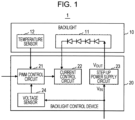
- Fig. 1 illustrates an example of the structure of a liquid crystal display unit, in which a power supply circuit protection device and backlight control device in a first embodiment are applied, the backlight control device being in a step-up constant-current driving method.
- the liquid crystal display unit 1 in the first embodiment is mounted in, for example, a vehicle.
- the display on the liquid crystal display unit 1 is controlled by an electronic device mounted in the vehicle.
- the liquid crystal display unit 1 in the first embodiment has a backlight 10 and a backlight control device 20.
- the backlight 10 has an LED matrix 11 and a temperature sensor 12.
- the LED matrix 11 is equivalent to a circuit eligible for being controlled in the scope of the claims.
- the temperature sensor 12 is equivalent to a temperature detection unit in the scope of the claims.
- the backlight control device 20 has a PWM control circuit 21, a current control circuit 22, a step-up power supply circuit 23, and a voltage sensor 24.
- the power supply circuit protection device in the first embodiment is composed of the PWM control circuit 21, current control circuit 22, and voltage sensor 24.
- the PWM control circuit 21 is equivalent to a control signal generation unit in the scope of the claims.
- the current control circuit 22 is equivalent to a target circuit control unit in the scope of the claims.
- the step-up power supply circuit 23 is equivalent to a power supply circuit in the scope of the claims.
- the voltage sensor 24 is equivalent to a voltage detection unit in the scope of the claims.
- the LED matrix 11 in the backlight 10 is composed of a plurality of LEDs. Although, in Fig. 1 , only one LED row, in which LEDs are connected in series, is illustrated to simplify the drawing, there are a plurality of LED rows, each of which has a structure similar to the structure of the one LED row. A plurality of LED rows are connected in parallel to form the LED matrix 11.
- the step-up power supply circuit 23 in the backlight control device 20 raises an input voltage V IN to a predetermined voltage higher than it and then applies an output voltage V OUT , resulting from the raising, to the anode side of the LED matrix 11.
- the input voltage V IN is, for example, a power supply voltage supplied from a battery (not illustrated) mounted in a vehicle.
- the magnitude of the voltage supplied from the battery mounted in the vehicle to the step-up power supply circuit 23 may vary depending on the situation in which the vehicle travels.
- the PWM control circuit 21 generates a control signal composed of a pulse wave having a duty cycle with a variable setting. Specifically, the PWM control circuit 21 generates a PWM signal composed of a pulse wave having a duty cycle that is set according to a time ratio matching a dimming ratio specified outside the backlight control device 20 and then supplies the PWM signal to the current control circuit 22 as a control signal.
- the dimming ratio can be specified through a manipulation by the user on an electronic device that causes an indication to be displayed on the liquid crystal display unit 1 in this embodiment. Alternatively, the dimming ratio can be automatically specified by an electronic device according to the illumination in the room of the vehicle, the illumination being detected by an illumination sensor provided in the room.
- the current control circuit 22 controls the operation of the LED matrix 11 in response to the PWM signal generated by the PWM control circuit 21. Specifically, during a period in which the pulse of the PWM signal supplied from the PWM control circuit 21 is turned on, the current control circuit 22 draws a constant current from the cathode side of the LED matrix 11 to control the dimming of the LED matrix 11.
- the temperature sensor 12 in the backlight 10 detects the ambient temperature affected by heat generated by the LED matrix 11 (temperature generated in the backlight 10) and notifies the PWM control circuit 21 of the ambient temperature.
- the PWM control circuit 21 sets the duty cycle of the PWM signal to a value smaller than a duty cycle setting at a normal time to suppress heat generated by the LED matrix 11 and protect the LED matrix 11.
- the predetermined temperature condition is that the ambient temperature detected by the temperature sensor 12 is higher than a predetermined temperature threshold Tht.
- the duty cycle setting at the normal time refers to a duty cycle setting in which the specified dimming ratio is reflected without alteration.
- the duty cycle can be set to a value smaller than the duty cycle setting at the normal time in any way.
- the ratio of the duration of the period during which the PWM signal is turned on may be set so as to be lower than at the normal time by a predetermined percentage.
- the duration of the period during which the PWM signal is turned on may be set so as to be shorter than at the normal time by a predetermined time.
- the voltage sensor 24 detects the input voltage V IN to be supplied to the step-up power supply circuit 23 and notifies the PWM control circuit 21 of the input voltage V IN .
- the PWM control circuit 21 sets the duty cycle of the PWM signal to a value smaller than the duty cycle setting at the normal time to reduce the load of the step-up power supply circuit 23 and protect parts in the step-up power supply circuit 23 from breakdown, which would otherwise be caused due to a high load.
- the predetermined voltage condition is that the input voltage V IN detected by the voltage sensor 24 is lower than a predetermined voltage threshold Th v .
- Th v the predetermined voltage threshold
- the difference between this input voltage V IN and the predetermined output voltage V OUT becomes large. Therefore, it is assumed that a high load is applied to raise the input voltage V IN to the predetermined output voltage V OUT .
- the duty cycle of the PWM signal is set to a value smaller than the duty cycle setting at the normal time.
- Fig. 2 illustrates control by the PWM control circuit 21 in the first embodiment. Specifically, Fig. 2 illustrates a case in which the duty cycle of the PWM signal is set to a value smaller than the duty cycle setting at the normal time.
- the vertical axis indicates the ambient temperature, detected by the temperature sensor 12, of the LED matrix 11, and the horizontal axis indicates the input voltage V IN , detected by the voltage sensor 24, to the step-up power supply circuit 23.
- the duty cycle of the PWM signal is set to a value smaller than the duty cycle setting at the normal time.
- the PWM control circuit 21 sets the duty cycle of the PWM signal to a value smaller than to the duty cycle setting at the normal time.
- the current consumption of the LED matrix 11 can be reduced. This reduces the load of the LED matrix 11, enabling parts in the LED matrix 11 to be protected from breakdown.
- the input voltage V IN to the step-up power supply circuit 23 satisfies the predetermined voltage condition
- the duty cycle of the PWM signal when the duty cycle of the PWM signal is lowered, the current consumption of the LED matrix 11 can be reduced and the output current consumption of the step-up power supply circuit 23 can thereby be reduced. This can suppress a power loss in the step-up power supply circuit 23, enabling parts in the step-up power supply circuit 23 to be protected from breakdown.
- Fig. 3 is a flowchart illustrating an example of the operation of the backlight control device 20 in the first embodiment.
- the flowchart in Fig. 3 starts when the power supply of the backlight control device 20 is turned on.
- this flowchart only an operation involved in the substance of the first embodiment is illustrated and a dimming operation and the like at the normal time are omitted.
- the PWM control circuit 21 decides whether the ambient temperature, detected by the temperature sensor 12, of the LED matrix 11 is higher than the predetermined temperature threshold Th t (step S1). If the PWM control circuit 21 decides that the ambient temperature of the LED matrix 11 is higher than the predetermined temperature threshold Tht, the PWM control circuit 21 sets the duty cycle of the PWM signal to a value smaller than the duty cycle setting at the normal time (step S3).
- the PWM control circuit 21 decides that the ambient temperature of the LED matrix 11 is not higher than the predetermined temperature threshold Th t , the PWM control circuit 21 further decides whether the input voltage V IN , detected by the voltage sensor 24, to the step-up power supply circuit 23 is lower than the predetermined voltage threshold Th v (step S2). If the PWM control circuit 21 decides that the input voltage V IN to the step-up power supply circuit 23 is lower than the predetermined voltage threshold Th v , the PWM control circuit 21 sets the duty cycle of the PWM signal to a value smaller than the duty cycle setting at the normal time (step S3).
- step S4 the backlight control device 20 decides whether to terminate the process.
- the backlight control device 20 decides whether a manipulation to turn off the power supply of the backlight control device 20 has been performed. If a manipulation to turn off the power supply has not been performed, the process returns to step S1. If a manipulation to turn off the power supply of has been performed, the process in the flowcharts in Fig. 3 is terminated.
- the voltage sensor 24 is provided that detects the input voltage V IN to be supplied to the step-up power supply circuit 23.
- the PWM control circuit 21 When it is sensed that the input voltage V IN detected by the voltage sensor 24 satisfies a predetermined voltage condition, the PWM control circuit 21 generates a PWM signal having a duty cycle set to a value smaller than the duty cycle setting at the normal time. Then, the current control circuit 22 controls the operation, of the LED matrix 11, by which a constant current is drawn from the LED matrix 11, according to the PWM signal.
- the load of the step-up power supply circuit 23 correlates to the magnitude of the input voltage V IN
- the load of the step-up power supply circuit 23 can be more accurately detected than when the ambient temperature of the step-up power supply circuit 23 is detected by a temperature sensor.
- the duty cycle of the PWM signal is set to a value smaller than the duty cycle setting at the normal time to reduce the load applied to the step-up power supply circuit 23. Therefore, it is possible to protect parts in the step-up power supply circuit 23 from breakdown.
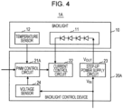
- Fig. 4 illustrates an example of the structure of a liquid crystal display unit, in which a power supply circuit protection device and backlight control device in a second embodiment are applied, the backlight control device being in a step-up constant-current driving method.
- the liquid crystal display unit 1A in the second embodiment is also mounted in, for example, a vehicle.
- the display on the liquid crystal display unit 1A is controlled by an electronic device mounted in the vehicle.
- the liquid crystal display unit 1A in the second embodiment has a backlight control device 20A instead of the backlight control device 20.
- the backlight control device 20A has a PWM control circuit 21A instead of the PWM control circuit 21.
- a predetermined complex voltage-and-temperature condition is used instead of the predetermined voltage condition described in the first embodiment.
- the PWM control circuit 21A sets the duty cycle of the PWM signal to a value smaller than a duty cycle setting at the normal time.
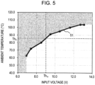
- Fig. 5 illustrates control by the PWM control circuit 21A in the second embodiment.
- the vertical axis indicates the ambient temperature, detected by the temperature sensor 12, of the LED matrix 11, and the horizontal axis indicates the input voltage V IN , detected by the voltage sensor 24, to the step-up power supply circuit 23.
- the input voltage V IN to the step-up power supply circuit 23 and the ambient temperature of the LED matrix 11 satisfy the predetermined complex voltage-and-temperature condition, that is, the duty cycle of the PWM signal is set to a value smaller than the duty cycle setting at the normal time.
- a borderline 51 in Fig. 5 indicates a limit up to which the duty cycle of the PWM signal is set or is not set to a low setting.
- the borderline 51 can be said to indicate, for each value of the input voltage V IN to the step-up power supply circuit 23, a temperature threshold that the ambient temperature, detected by the temperature sensor 12, of the LED matrix 11 must exceed.
- the borderline 51 can be said to indicate, for each value of the ambient temperature of the LED matrix 11, a voltage threshold that the input voltage V IN , detected by the voltage sensor 24, to the step-up power supply circuit 23 must fall below.
- This borderline 51 is set according to actual measurements by, for example, the temperature sensor 12 and voltage sensor 24. Specifically, the value of the input voltage V IN to be supplied to the step-up power supply circuit 23 is successively changed in a state in which the PWM control circuit 21A generates a PWM signal according to a certain dimming ratio and the current control circuit 22 controls the LED matrix 11 according to this PWM signal.
- the temperature sensor 12 and voltage sensor 24 detect temperatures and voltages for each plurality of input voltages V IN . The detected values are plotted on the coordinate system in Fig. 5 .
- the black circles on the borderline 51 indicate a plurality of plots. To set the borderline 51, a certain function is used for interpolation between black circles. Alternatively, an approximating curve that approximates a plurality of plots may be obtained and may be set as the borderline 51.
- the duty cycle of the PWM signal has been consistently lowered.
- the duty cycle of the PWM signal is lowered. This can widen the range in which the backlight 10 can be maintained at high brightness.
- the duty cycle of the PWM signal has been consistently lowered.
- the duty cycle of the PWM signal is lowered. This can widen the range in which the backlight 10 can be maintained at high brightness.
- Fig. 6 is a flowchart illustrating an example of the operation of the backlight control device 20A in the second embodiment.
- the flowchart in Fig. 6 starts when the power supply of the backlight control device 20A is turned on.
- this flowchart only an operation involved in the substance of the second embodiment is illustrated and a dimming operation and the like at the normal time are omitted.
- the PWM control circuit 21A decides whether the ambient temperature, detected by the temperature sensor 12, of the LED matrix 11 and the input voltage V IN , detected by the voltage sensor 24, to the step-up power supply circuit 23 satisfy the predetermined complex voltage-and-temperature condition prescribed by the borderline 51 in Fig. 5 (step S11). If the PWM control circuit 21A decides that the predetermined complex voltage-and-temperature condition is satisfied, the PWM control circuit 21A sets the duty cycle of the PWM signal to a value smaller than the duty cycle setting at the normal time (step S12).
- step S13 the backlight control device 20A decides whether to terminate the process.
- the backlight control device 20A decides whether a manipulation to turn off the power supply of the backlight control device 20A has been performed. If a manipulation to turn off the power supply has not been performed, the process returns to step S11. If a manipulation to turn off the power supply has been performed, the process in the flowcharts in Fig. 6 is terminated.
- Fig. 7 illustrates an example of the structure of a liquid crystal display unit, in which a power supply circuit protection device and backlight control device in a third embodiment are applied, the backlight control device being in a step-up constant-current driving method.
- the liquid crystal display unit 1B in the third embodiment is also mounted in, for example, a vehicle.
- the display on the liquid crystal display unit 1B is controlled by an electronic device mounted in the vehicle.
- the liquid crystal display unit 1B in the third embodiment has a backlight control device 20B instead of the backlight control device 20A.
- the backlight control device 20B has a PWM control circuit 21B and a step-up power supply circuit 23B instead of the PWM control circuit 21A and step-up power supply circuit 23.
- the PWM control circuit 21B sets the duty cycle of the PWM signal to a value smaller than the duty cycle setting at the normal time.
- the PWM control circuit 21B controls the step-up power supply circuit 23B so that a boosting range by which to raise the input voltage V IN to the output voltage V OUT becomes narrower than a boosting range at the normal time, and sets the duty cycle of the PWM signal to a value equal to or greater than the duty cycle setting at the normal time.
- Fig. 8 illustrates control by the PWM control circuit 21B in the third embodiment.
- the vertical axis indicates the ambient temperature, detected by the temperature sensor 12, of the LED matrix 11, and the horizontal axis indicates the input voltage V IN , detected by the voltage sensor 24, to the step-up power supply circuit 23B.
- a first borderline 51 in Fig. 8 is identical to the borderline 51 in Fig. 5 .
- the third embodiment differs from the second embodiment illustrated in Fig 5 in that the filled-in area is divided into two areas by a second borderline 52. In one of them, the ambient temperature is higher than the predetermined temperature threshold Th t . In the other area, the ambient temperature is lower than or equal to the predetermined temperature threshold Tht.
- the PWM control circuit 21B sets the duty cycle of the PWM signal to a value smaller than the duty cycle setting at the normal time, as in the second embodiment.
- the PWM control circuit 21B controls the step-up power supply circuit 23B so that the boosting range in the step-up power supply circuit 23B becomes narrower than the boosting range at the normal time.
- the PWM control circuit 21B maintains the duty cycle of the PWM signal at the duty cycle setting at the normal time or sets the duty cycle to a value greater than at the normal time.
- the output voltage V OUT from the step-up power supply circuit 23B is lowered to reduce the load due to boosting by the step-up power supply circuit 23 and the duty cycle of the PWM signal is maintained at the duty cycle setting at the normal time or set to a value greater than at the normal time, it is possible to restrain the brightness of the backlight 10 from being lowered.
- Table 1 indicates the operation in the areas, filled in with the first borderline 51 taken as a boundary, in which the predetermined complex voltage-and-temperature condition is satisfied.
- Table 1 Input voltage ⁇ Th v Input voltage ⁇ Th v Ambient temperature ⁇ Th t - - - Narrow the boosting range, and maintain or raise the duty cycle of the PWM signal.
- Ambient temperature > Th t Lower the duty cycle of the PWM signal. Lower the duty cycle of the PWM signal.
- Fig. 9 is a flowchart illustrating an example of the operation of the backlight control device 20B in the third embodiment.
- the flowchart in Fig. 9 starts when the power supply of the backlight control device 20B is turned on.
- this flowchart only an operation involved in the substance of the third embodiment is illustrated and a dimming operation and the like at the normal time are omitted.
- the PWM control circuit 21B decides whether the ambient temperature, detected by the temperature sensor 12, of the LED matrix 11 and the input voltage V IN , detected by the voltage sensor 24, to the step-up power supply circuit 23 satisfy the predetermined complex voltage-and-temperature condition prescribed by the first borderline 51 in Fig. 8 (step S21). If the PWM control circuit 21B decides that the predetermined complex voltage-and-temperature condition is satisfied, the PWM control circuit 21B further decides whether the ambient temperature, detected by the temperature sensor 12, of the LED matrix 11 is higher than the predetermined temperature threshold Th t (step S22).
- the PWM control circuit 21B decides that the ambient temperature of the LED matrix 11 is higher than the predetermined temperature threshold Tht, the PWM control circuit 21B sets the duty cycle of the PWM signal to a value smaller than the duty cycle setting at the normal time (step S23). If the PWM control circuit 21B decides that the ambient temperature of the LED matrix 11 is not higher than the predetermined temperature threshold Th t , the PWM control circuit 21B controls the step-up power supply circuit 23B so that the boosting range in the step-up power supply circuit 23B becomes narrower than the boosting range at the normal time, and sets the duty cycle of the PWM signal to a value, which is, for example, greater than the duty cycle setting at the normal time (step S24).
- step S21 if the PWM control circuit 21B decides that the predetermined complex voltage-and-temperature condition is not satisfied, the process proceeds to step S25. Upon the completion of the execution of processing in step S23 or S24, the process also proceeds to step S25.
- step S25 the backlight control device 20B decides whether to terminate the process. Here, the backlight control device 20B decides whether a manipulation to turn off the power supply of the backlight control device 20B has been performed. If a manipulation to turn off the power supply has not been performed, the process returns to step S21. If a manipulation to turn off the power supply has been performed, the process in the flowcharts in Fig. 9 is terminated.
- the PWM control circuit 21B has been notified of the input voltage V IN , detected by the voltage sensor 24, to the step-up power supply circuit 23B and has controlled the boosting range in the step-up power supply circuit 23B accordingly.
- the present invention is not limited to this structure.
- the PWM control circuit 21B may notifies the step-up power supply circuit 23B whether the predetermined complex voltage-and-temperature condition is satisfied and may also notify the step-up power supply circuit 23B of the ambient temperature, detected by the temperature sensor 12, of the LED matrix 11. Then, the step-up power supply circuit 23B may decide whether the ambient temperature of the LED matrix 11 is higher than the predetermined temperature threshold Tht and may control the boosting range by itself according to the decision result. This is also true for a fourth embodiment described below.
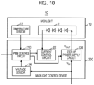
- Fig. 10 illustrates an example of the structure of a liquid crystal display unit in which a power supply circuit protection device and backlight control device in a fourth embodiment are applied, the backlight control device being in a step-up constant-current driving method.
- the liquid crystal display unit 1C in the fourth embodiment is also mounted in, for example, a vehicle.
- the display on the liquid crystal display unit 1C is controlled by an electronic device mounted in the vehicle.
- the liquid crystal display unit 1C in the fourth embodiment has a backlight control device 20C instead of the backlight control device 20B.
- the backlight control device 20C has a PWM control circuit 21C instead of the PWM control circuit 21B.
- Fig. 11 illustrates control by the PWM control circuit 21C in the fourth embodiment.
- the vertical axis indicates the ambient temperature, detected by the temperature sensor 12, of the LED matrix 11, and the horizontal axis indicates the input voltage V IN , detected by the voltage sensor 24, to the step-up power supply circuit 23B.
- the borderlines 51 and 52 in Fig. 11 are identical to those in Fig. 8 .
- the fourth embodiment differs from the third embodiment illustrated in Fig 8 in that the area above the second borderline 52 is divided into two areas by a third borderline 53. In one of them, the ambient temperature is lower than the predetermined voltage threshold Th v . In the other area, the ambient temperature is higher than or equal to the predetermined voltage threshold Th v .
- control by the PWM control circuit 21C is as in the second embodiment.
- the PWM control circuit 21C controls the step-up power supply circuit 23B so that the boosting range in the step-up power supply circuit 23B becomes narrower than the boosting range at the normal time.
- the PWM control circuit 21C maintains the duty cycle of the PWM signal at the duty cycle setting at the normal time or sets the duty cycle to a value greater than at the normal time.
- control by the PWM control circuit 21C is also as in the second embodiment.
- the PWM control circuit 21C sets the boosting range in the step-up power supply circuit 23B to the boosting range at the normal time, and also sets the duty cycle of the PWM signal to a value smaller than at the duty cycle setting at the normal time.
- control by the PWM control circuit 21C is performed as described below.
- the PWM control circuit 21C controls the step-up power supply circuit 23B so that the boosting range in the step-up power supply circuit 23B becomes narrower than the boosting range at the normal time, and sets the duty cycle of the PWM signal to a value smaller than at the normal time.
- the third embodiment may be applied when a mode to prioritize the securing of brightness of the backlight 10 is specified, and the fourth embodiment may be applied when a mode to prioritize protection of parts from breakdown is specified.
- Table 2 indicates the operation in the area, filled in with the first borderline 51 taken as a boundary, in which the predetermined complex voltage-and-temperature condition is satisfied.
- Table 2 Input voltage ⁇ Th v Input voltage ⁇ Th v Ambient temperature ⁇ Th t - - - Narrow the boosting range, and maintain or raise the duty cycle of the PWM signal.
- Ambient temperature > Tht Lower the duty cycle of the PWM signal.
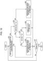
- Fig. 12 is a flowchart illustrating an example of the operation of the backlight control device 20C in the fourth embodiment.
- the flowchart in Fig. 12 starts when the power supply of the backlight control device 20C is turned on.
- this flowchart only an operation involved in the substance of the fourth embodiment is illustrated and a dimming operation and the like at the normal time are omitted.
- the PWM control circuit 21C decides whether the ambient temperature, detected by the temperature sensor 12, of the LED matrix 11 and the input voltage V IN , detected by the voltage sensor 24, to the step-up power supply circuit 23 satisfy the predetermined complex voltage-and-temperature condition prescribed by the first borderline 51 in Fig. 11 (step S31). If the PWM control circuit 21C decides that the predetermined complex voltage-and-temperature condition is satisfied, the PWM control circuit 21C further decides whether the ambient temperature, detected by the temperature sensor 12, of the LED matrix 11 is higher than the predetermined temperature threshold Th t (step S32).
- the PWM control circuit 21C decides that the ambient temperature of the LED matrix 11 is higher than the predetermined temperature threshold Th t , the PWM control circuit 21C further decides whether the input voltage V IN , detected by the voltage sensor 24, to the step-up power supply circuit 23B is lower than the predetermined voltage threshold Th v (step S33).
- the PWM control circuit 21C decides that the input voltage V IN to the step-up power supply circuit 23B is lower than the predetermined voltage threshold Th v , the PWM control circuit 21C controls the step-up power supply circuit 23B so that the boosting range in the step-up power supply circuit 23B becomes narrower than the boosting range at the normal time, and sets the duty cycle of the PWM signal to a value smaller than the duty cycle setting at the normal time (step S34).
- step S33 If the PWM control circuit 21C decides in step S33 that the input voltage V IN is not lower than the predetermined voltage threshold Th v , the PWM control circuit 21C maintains the boosting range in the step-up power supply circuit 23B at the boosting range at the normal time, and sets the duty cycle of the PWM signal to a value smaller than the duty cycle setting at the normal time (step S35).
- step S32 If the PWM control circuit 21C decides in step S32 above that the ambient temperature of the LED matrix 11 is not higher than the predetermined temperature threshold Th t , the PWM control circuit 21C controls the step-up power supply circuit 23B so that the boosting range in the step-up power supply circuit 23B becomes narrower than the boosting range at the normal time, and sets the duty cycle of the PWM signal to a value, which is, for example, greater than the duty cycle setting at the normal time (step S36).
- step S31 If the PWM control circuit 21C decides in step S31 above that predetermined complex voltage-and-temperature condition is not satisfied, the process proceeds to step S37. Upon the completion of the execution of processing in any one of steps S34 to S36, the process also proceeds to step S37.
- step S37 the backlight control device 20C decides whether to terminate the process. Here, the backlight control device 20C decides whether a manipulation to turn off the power supply of the backlight control device 20C has been performed. If a manipulation to turn off the power supply has not been performed, the process returns to step S31. If a manipulation to turn off the power supply of has been performed, the process in the flowcharts in Fig. 12 is terminated.
- first to fourth embodiments have been just described as examples to embody the present invention. It should not be interpreted that these embodiments limit the technical range of the present invention.
- a liquid crystal display unit mounted in a vehicle has been taken as an example in the descriptions of the above first to fourth embodiments
- the present invention can also be applied to liquid crystal display units that are not mounted in vehicles.
- Examples in which a power supply circuit protection device is applied to a backlight control device have been also described in the above first to fourth embodiments.
- circuits eligible for being controlled are not limited to backlights. When a circuit other than a backlight is used as the circuit eligible for being controlled, the temperature sensor 12 is likely to be eliminated. If the temperature sensor 12 is eliminated, control of the duty cycle of the PWM signal is omitted, which would other be performed according to the ambient temperature of the circuit eligible for being controlled.
- the power supply circuit may be a step-down power supply circuit that lowers an input voltage and applies an output voltage, resulting from lowering, to the circuit eligible for being controlled as the power supply voltage. It is also possible to apply the power supply circuit protection device in the above embodiments to a backlight control device in, for example, a step-down constant-current driving method or a step-up/down constant-current driving method.
- the predetermined voltage condition is that the input voltage detected by the voltage sensor 24 is higher than or equal to a predetermined voltage threshold.
Landscapes
- Engineering & Computer Science (AREA)
- Physics & Mathematics (AREA)
- General Physics & Mathematics (AREA)
- Power Engineering (AREA)
- Computer Hardware Design (AREA)
- Theoretical Computer Science (AREA)
- Dc-Dc Converters (AREA)
- Circuit Arrangement For Electric Light Sources In General (AREA)
Abstract
A power supply circuit protection device has a PWM control circuit and a voltage sensor that detects an input voltage to be supplied to a step-up power supply circuit. When it is sensed that the input voltage detected by the voltage sensor satisfies a predetermined voltage condition, the PWM control circuit sets the duty cycle of a PWM signal to a value smaller than a duty cycle setting at a normal time. On the basis that the load of the step-up power supply circuit correlates to the input voltage, the input voltage to the step-up power supply circuit is detected by the voltage sensor. This enables the load of the step-up power supply circuit to be more accurately detected. Therefore, when the duty cycle of the PWM signal is set to a value smaller than at the normal time, the load of the step-up power supply circuit is reduced.
Description
- The present invention relates to a power supply circuit protection device and a power supply circuit protection method, and more particularly to a device and method that protect parts in a power supply circuit from breakdown and a backlight control device in which the device is used.
- In a conventionally provided backlight for an environment-friendly liquid crystal display (LCD) in which mercury is not used, an array of light-emitting diodes (LEDs) is used as a light source. When an array of LEDs is used as the light source of a backlight, there is a demand to drive the LEDs with a constant current so that changes in chromaticity are minimized. A step-up constant-current driving method, a step-down constant-current driving method, and a step-up/down constant-current driving method are available as a method of driving LEDs with a constant current. In a vehicle-mounted liquid crystal display unit, for example, a step-up power supply circuit is used to obtain high brightness and pulse-width modulation (PWM) signals are used in display brightness adjustment.
-
Fig. 13 schematically illustrates an example of the structure of a liquid crystal display unit in which a conventional backlight control device in a step-up constant-current driving method is used. The conventional liquidcrystal display unit 100 inFig. 13 has abacklight 110 and abacklight control device 120. Thebacklight 110 has anLED matrix 111 and atemperature sensor 112. Thebacklight control device 120 has aPWM control circuit 121, acurrent control circuit 122, and a step-uppower supply circuit 123. - The
LED matrix 111 in thebacklight 110 is composed of a plurality of LEDs. Although, inFig. 13 , only one LED row, in which LEDs are connected in series, is illustrated to simplify the drawing, there are a plurality of LED rows, each of which has a structure similar to the structure of the one LED row. A plurality of LED rows are connected in parallel to form theLED matrix 111. - The step-up
power supply circuit 123 in thebacklight control device 120 raises an input voltage VIN to a predetermined voltage higher than it and then applies an output voltage VOUT, resulting from the raising, to the anode side of theLED matrix 111. The input voltage VIN is, for example, a power supply voltage supplied from a battery (not illustrated) mounted in a vehicle. - The
PWM control circuit 121 andcurrent control circuit 122 are used for dimming of theLED matrix 111. ThePWM control circuit 121 generates a PWM signal composed of a pulse wave the duty cycle of which is set according to a time ratio matching a dimming ratio and then supplies the PWM signal to thecurrent control circuit 122. In a period during which the pulse of the PWM signal is turned on, thecurrent control circuit 122 draws a constant current from the cathode side of theLED matrix 111 to control dimming of theLED matrix 111. - The
temperature sensor 112 in thebacklight 110 detects temperature in thebacklight 110 and notifies thePWM control circuit 121 of the temperature. When thePWM control circuit 121 senses that the temperate detected by thetemperature sensor 112 has reached or exceeded a predetermined value, thePWM control circuit 121 lowers the duty cycle of the PWM signal to suppress heat generated by theLED matrix 111 and thereby protect theLED matrix 111. Technologies that control dimming according to the result of detection by thetemperature sensor 112 as described above are disclosed in, for example,JP2010-49809 A JP2015-13560 A - As the sizes of recent displays has been increased, further higher brightness is demanded for the backlight, so the loads of parts used in the step-up
power supply circuit 123 has been increased. Particularly, this is problematic when the input voltage VIN to be supplied to the step-uppower supply circuit 123 is a low voltage, in which case a boosting range by which to raise the input voltage VIN to the output voltage VOUT becomes large, increasing a load due to a power loss. At the worst, a part is destroyed due to heat generated by the step-uppower supply circuit 123 itself. - A possible solution to the above problem is to detect the amount of heat generated in the step-up
power supply circuit 123 with a temperature sensor attached in the vicinity of the step-uppower supply circuit 123 for protection purposes. However, even when a temperature sensor is attached in the vicinity of the step-uppower supply circuit 123, a difference in temperature is likely to occur depending on the position at which the temperature sensor is attached. Furthermore, the ambient temperature is included in the sensed temperature. Therefore, it is difficult to use a temperature sensor to accurately determine a high load due to a power loss. - A known technology protects a step-up direct current (DC)-direct current (DC) converter configured to provide an output voltage stabilized by pulse-width control when an input voltage to the DC-DC converter falls to or below a voltage setting, by stopping the operation of a control integrated circuit (IC) (see
JP7-177730 A JP7-177730 A power supply circuit 123 falls to or below the voltage setting, the operation of the step-uppower supply circuit 123 stops, causing the display to be blacked out. - The present invention addresses the above problem with the object of more accurately detecting the load of a power supply circuit and protecting parts in the power supply circuit from breakdown.
- The invention relates to a device and method according to the appended claims. Embodiments are disclosed in the dependent claims.
- In an aspect of the present invention, a voltage detection unit is provided that detects an input voltage to be supplied to a power supply circuit that transforms the input voltage and applies, as a power supply voltage, an output voltage, resulting from the transformation, to a circuit eligible for being controlled. When it is sensed that the input voltage detected by the voltage detection unit satisfies a predetermined voltage condition, a control signal is generated that is composed of a pulse wave having a duty cycle set to a value smaller than a duty cycle setting at a normal time. The operation of the circuit eligible for being controlled is controlled according to the control signal.
- In a configuration as described above, since the load of the power supply circuit correlates to the magnitude of the input voltage, when the input voltage is detected by the voltage detection unit, the load of the power supply circuit can be more accurately detected than when the ambient temperature of the power supply circuit is detected. When it is sensed that the detected input voltage satisfies a predetermined voltage condition, the duty cycle of the control signal is set to a value smaller than the duty cycle setting at the normal time to reduce the load applied to the power supply circuit, under the assumption that a high load has been applied to the power supply circuit. Therefore, it is possible to protect parts in the power supply circuit from breakdown.
-
Fig. 1 illustrates an example of the structure of a liquid crystal display unit, in which a power supply circuit protection device and backlight control device in a first embodiment are applied, the backlight control device being in a step-up constant-current driving method; -
Fig. 2 illustrates control by a PWM control circuit in the first embodiment; -
Fig. 3 is a flowchart illustrating an example of the operation of the backlight control device in the first embodiment; -
Fig. 4 illustrates an example of the structure of a liquid crystal display unit, in which a power supply circuit protection device and backlight control device in a second embodiment are applied, the backlight control device being in a step-up constant-current driving method; -
Fig. 5 illustrates control by a PWM control circuit in the second embodiment; -
Fig. 6 is a flowchart illustrating an example of the operation of the backlight control device in the second embodiment; -
Fig. 7 illustrates an example of the structure of a liquid crystal display unit, in which a power supply circuit protection device and backlight control device in a third embodiment are applied, the backlight control device being in a step-up constant-current driving method; -
Fig. 8 illustrates control by a PWM control circuit in the third embodiment; -
Fig. 9 is a flowchart illustrating an example of the operation of the backlight control device in the third embodiment; -
Fig. 10 illustrates an example of the structure of a liquid crystal display unit in which a power supply circuit protection device and backlight control device in a fourth embodiment are applied, the backlight control device being in a step-up constant-current driving method; -
Fig. 11 illustrates control by a PWM control circuit in the fourth embodiment; -
Fig. 12 is a flowchart illustrating an example of the operation of the backlight control device in the fourth embodiment; and -
Fig. 13 schematically illustrates an example of the structure of a liquid crystal display unit in which a conventional backlight control device in a step-up constant-current driving method is used. - A first embodiment of the present invention will be described below with reference to the drawings.
Fig. 1 illustrates an example of the structure of a liquid crystal display unit, in which a power supply circuit protection device and backlight control device in a first embodiment are applied, the backlight control device being in a step-up constant-current driving method. The liquidcrystal display unit 1 in the first embodiment is mounted in, for example, a vehicle. The display on the liquidcrystal display unit 1 is controlled by an electronic device mounted in the vehicle. - As illustrated in
Fig. 1 , the liquidcrystal display unit 1 in the first embodiment has abacklight 10 and abacklight control device 20. Thebacklight 10 has anLED matrix 11 and atemperature sensor 12. TheLED matrix 11 is equivalent to a circuit eligible for being controlled in the scope of the claims. Thetemperature sensor 12 is equivalent to a temperature detection unit in the scope of the claims. - The
backlight control device 20 has aPWM control circuit 21, acurrent control circuit 22, a step-uppower supply circuit 23, and avoltage sensor 24. The power supply circuit protection device in the first embodiment is composed of thePWM control circuit 21,current control circuit 22, andvoltage sensor 24. ThePWM control circuit 21 is equivalent to a control signal generation unit in the scope of the claims. Thecurrent control circuit 22 is equivalent to a target circuit control unit in the scope of the claims. The step-uppower supply circuit 23 is equivalent to a power supply circuit in the scope of the claims. Thevoltage sensor 24 is equivalent to a voltage detection unit in the scope of the claims. - The
LED matrix 11 in thebacklight 10 is composed of a plurality of LEDs. Although, inFig. 1 , only one LED row, in which LEDs are connected in series, is illustrated to simplify the drawing, there are a plurality of LED rows, each of which has a structure similar to the structure of the one LED row. A plurality of LED rows are connected in parallel to form theLED matrix 11. - The step-up
power supply circuit 23 in thebacklight control device 20 raises an input voltage VIN to a predetermined voltage higher than it and then applies an output voltage VOUT, resulting from the raising, to the anode side of theLED matrix 11. The input voltage VIN is, for example, a power supply voltage supplied from a battery (not illustrated) mounted in a vehicle. The magnitude of the voltage supplied from the battery mounted in the vehicle to the step-uppower supply circuit 23 may vary depending on the situation in which the vehicle travels. - The
PWM control circuit 21 generates a control signal composed of a pulse wave having a duty cycle with a variable setting. Specifically, thePWM control circuit 21 generates a PWM signal composed of a pulse wave having a duty cycle that is set according to a time ratio matching a dimming ratio specified outside thebacklight control device 20 and then supplies the PWM signal to thecurrent control circuit 22 as a control signal. The dimming ratio can be specified through a manipulation by the user on an electronic device that causes an indication to be displayed on the liquidcrystal display unit 1 in this embodiment. Alternatively, the dimming ratio can be automatically specified by an electronic device according to the illumination in the room of the vehicle, the illumination being detected by an illumination sensor provided in the room. - The
current control circuit 22 controls the operation of theLED matrix 11 in response to the PWM signal generated by thePWM control circuit 21. Specifically, during a period in which the pulse of the PWM signal supplied from thePWM control circuit 21 is turned on, thecurrent control circuit 22 draws a constant current from the cathode side of theLED matrix 11 to control the dimming of theLED matrix 11. - The
temperature sensor 12 in thebacklight 10 detects the ambient temperature affected by heat generated by the LED matrix 11 (temperature generated in the backlight 10) and notifies thePWM control circuit 21 of the ambient temperature. When it is sensed that the ambient temperate detected by thetemperature sensor 12 satisfies a predetermined temperature condition, thePWM control circuit 21 sets the duty cycle of the PWM signal to a value smaller than a duty cycle setting at a normal time to suppress heat generated by theLED matrix 11 and protect theLED matrix 11. - The predetermined temperature condition is that the ambient temperature detected by the
temperature sensor 12 is higher than a predetermined temperature threshold Tht. The duty cycle setting at the normal time refers to a duty cycle setting in which the specified dimming ratio is reflected without alteration. The duty cycle can be set to a value smaller than the duty cycle setting at the normal time in any way. For example, the ratio of the duration of the period during which the PWM signal is turned on may be set so as to be lower than at the normal time by a predetermined percentage. Alternatively, the duration of the period during which the PWM signal is turned on may be set so as to be shorter than at the normal time by a predetermined time. - The
voltage sensor 24 detects the input voltage VIN to be supplied to the step-uppower supply circuit 23 and notifies thePWM control circuit 21 of the input voltage VIN. When it is sensed that the input voltage VIN detected by thevoltage sensor 24 satisfies a predetermined voltage condition, thePWM control circuit 21 sets the duty cycle of the PWM signal to a value smaller than the duty cycle setting at the normal time to reduce the load of the step-uppower supply circuit 23 and protect parts in the step-uppower supply circuit 23 from breakdown, which would otherwise be caused due to a high load. - The predetermined voltage condition is that the input voltage VIN detected by the
voltage sensor 24 is lower than a predetermined voltage threshold Thv. When the input voltage VIN is lower than the predetermined voltage threshold Thv, the difference between this input voltage VIN and the predetermined output voltage VOUT becomes large. Therefore, it is assumed that a high load is applied to raise the input voltage VIN to the predetermined output voltage VOUT. In this embodiment, in this case as well, the duty cycle of the PWM signal is set to a value smaller than the duty cycle setting at the normal time. -
Fig. 2 illustrates control by thePWM control circuit 21 in the first embodiment. Specifically,Fig. 2 illustrates a case in which the duty cycle of the PWM signal is set to a value smaller than the duty cycle setting at the normal time. InFig. 2 , the vertical axis indicates the ambient temperature, detected by thetemperature sensor 12, of theLED matrix 11, and the horizontal axis indicates the input voltage VIN, detected by thevoltage sensor 24, to the step-uppower supply circuit 23. In the filled-in area inFig. 2 , the duty cycle of the PWM signal is set to a value smaller than the duty cycle setting at the normal time. - Specifically, as illustrated in
Fig. 2 , when it is sensed that the ambient temperature, detected by thetemperature sensor 12, of theLED matrix 11 is higher than the predetermined temperature threshold Tht or when it is sensed that the input voltage VIN, detected by thevoltage sensor 24, to the step-uppower supply circuit 23 is lower than the predetermined voltage threshold Thv, thePWM control circuit 21 sets the duty cycle of the PWM signal to a value smaller than to the duty cycle setting at the normal time. - In a case in which the ambient temperature of the
LED matrix 11 satisfies the predetermined temperature condition, when the duty cycle of the PWM signal is lowered, the current consumption of theLED matrix 11 can be reduced. This reduces the load of theLED matrix 11, enabling parts in theLED matrix 11 to be protected from breakdown. In a case as well in which the input voltage VIN to the step-uppower supply circuit 23 satisfies the predetermined voltage condition, when the duty cycle of the PWM signal is lowered, the current consumption of theLED matrix 11 can be reduced and the output current consumption of the step-uppower supply circuit 23 can thereby be reduced. This can suppress a power loss in the step-uppower supply circuit 23, enabling parts in the step-uppower supply circuit 23 to be protected from breakdown. -
Fig. 3 is a flowchart illustrating an example of the operation of thebacklight control device 20 in the first embodiment. The flowchart inFig. 3 starts when the power supply of thebacklight control device 20 is turned on. In this flowchart, only an operation involved in the substance of the first embodiment is illustrated and a dimming operation and the like at the normal time are omitted. - First, the
PWM control circuit 21 decides whether the ambient temperature, detected by thetemperature sensor 12, of theLED matrix 11 is higher than the predetermined temperature threshold Tht (step S1). If thePWM control circuit 21 decides that the ambient temperature of theLED matrix 11 is higher than the predetermined temperature threshold Tht, thePWM control circuit 21 sets the duty cycle of the PWM signal to a value smaller than the duty cycle setting at the normal time (step S3). - If the
PWM control circuit 21 decides that the ambient temperature of theLED matrix 11 is not higher than the predetermined temperature threshold Tht, thePWM control circuit 21 further decides whether the input voltage VIN, detected by thevoltage sensor 24, to the step-uppower supply circuit 23 is lower than the predetermined voltage threshold Thv (step S2). If thePWM control circuit 21 decides that the input voltage VIN to the step-uppower supply circuit 23 is lower than the predetermined voltage threshold Thv, thePWM control circuit 21 sets the duty cycle of the PWM signal to a value smaller than the duty cycle setting at the normal time (step S3). - If the
PWM control circuit 21 decides that the input voltage VIN to the step-uppower supply circuit 23 is not lower than the predetermined voltage threshold Thv, the process proceeds to step S4. Upon the completion of the execution of processing in step S3, the process also proceeds to step S4. In step S4, thebacklight control device 20 decides whether to terminate the process. Here, thebacklight control device 20 decides whether a manipulation to turn off the power supply of thebacklight control device 20 has been performed. If a manipulation to turn off the power supply has not been performed, the process returns to step S1. If a manipulation to turn off the power supply of has been performed, the process in the flowcharts inFig. 3 is terminated. - As described above in detail, in the first embodiment, the
voltage sensor 24 is provided that detects the input voltage VIN to be supplied to the step-uppower supply circuit 23. When it is sensed that the input voltage VIN detected by thevoltage sensor 24 satisfies a predetermined voltage condition, thePWM control circuit 21 generates a PWM signal having a duty cycle set to a value smaller than the duty cycle setting at the normal time. Then, thecurrent control circuit 22 controls the operation, of theLED matrix 11, by which a constant current is drawn from theLED matrix 11, according to the PWM signal. - In the first embodiment configured as described above, since the load of the step-up
power supply circuit 23 correlates to the magnitude of the input voltage VIN, when the input voltage VIN is detected by thevoltage sensor 24, the load of the step-uppower supply circuit 23 can be more accurately detected than when the ambient temperature of the step-uppower supply circuit 23 is detected by a temperature sensor. When it is sensed that the detected input voltage VIN satisfies a predetermined voltage condition, the duty cycle of the PWM signal is set to a value smaller than the duty cycle setting at the normal time to reduce the load applied to the step-uppower supply circuit 23. Therefore, it is possible to protect parts in the step-uppower supply circuit 23 from breakdown. - Next, a second embodiment of the present invention will be described with reference to the drawings.
Fig. 4 illustrates an example of the structure of a liquid crystal display unit, in which a power supply circuit protection device and backlight control device in a second embodiment are applied, the backlight control device being in a step-up constant-current driving method. The liquidcrystal display unit 1A in the second embodiment is also mounted in, for example, a vehicle. The display on the liquidcrystal display unit 1A is controlled by an electronic device mounted in the vehicle. - In
Fig. 4 , elements given the same reference numerals as inFig. 1 have the same functions as the corresponding elements inFig. 1 . Therefore, repeated descriptions will be omitted. As illustrated inFig. 4 , the liquidcrystal display unit 1A in the second embodiment has abacklight control device 20A instead of thebacklight control device 20. Thebacklight control device 20A has aPWM control circuit 21A instead of thePWM control circuit 21. - In the
PWM control circuit 21A, a predetermined complex voltage-and-temperature condition is used instead of the predetermined voltage condition described in the first embodiment. When it is sensed that the input voltage VIN, detected by thevoltage sensor 24, to the step-uppower supply circuit 23 and the ambient temperature, detected by thetemperature sensor 12, of theLED matrix 11 satisfy the predetermined complex voltage-and-temperature condition, thePWM control circuit 21A sets the duty cycle of the PWM signal to a value smaller than a duty cycle setting at the normal time. -
Fig. 5 illustrates control by thePWM control circuit 21A in the second embodiment. InFig. 5 , the vertical axis indicates the ambient temperature, detected by thetemperature sensor 12, of theLED matrix 11, and the horizontal axis indicates the input voltage VIN, detected by thevoltage sensor 24, to the step-uppower supply circuit 23. In the filled-in area inFig. 5 , the input voltage VIN to the step-uppower supply circuit 23 and the ambient temperature of theLED matrix 11 satisfy the predetermined complex voltage-and-temperature condition, that is, the duty cycle of the PWM signal is set to a value smaller than the duty cycle setting at the normal time. - A borderline 51 in
Fig. 5 indicates a limit up to which the duty cycle of the PWM signal is set or is not set to a low setting. The borderline 51 can be said to indicate, for each value of the input voltage VIN to the step-uppower supply circuit 23, a temperature threshold that the ambient temperature, detected by thetemperature sensor 12, of theLED matrix 11 must exceed. Alternatively, the borderline 51 can be said to indicate, for each value of the ambient temperature of theLED matrix 11, a voltage threshold that the input voltage VIN, detected by thevoltage sensor 24, to the step-uppower supply circuit 23 must fall below. - This borderline 51 is set according to actual measurements by, for example, the
temperature sensor 12 andvoltage sensor 24. Specifically, the value of the input voltage VIN to be supplied to the step-uppower supply circuit 23 is successively changed in a state in which thePWM control circuit 21A generates a PWM signal according to a certain dimming ratio and thecurrent control circuit 22 controls theLED matrix 11 according to this PWM signal. Thetemperature sensor 12 andvoltage sensor 24 detect temperatures and voltages for each plurality of input voltages VIN. The detected values are plotted on the coordinate system inFig. 5 . The black circles on the borderline 51 indicate a plurality of plots. To set the borderline 51, a certain function is used for interpolation between black circles. Alternatively, an approximating curve that approximates a plurality of plots may be obtained and may be set as the borderline 51. - When the duty cycle of the PWM signal is set to a value smaller than the duty cycle setting at the normal time, the brightness of the
backlight 10 is lowered. In the second embodiment, however, conditions under which the duty cycle of the PWM signal is set to a lower value can be more finely set than in the first embodiment. Therefore, a range in which thebacklight 10 can be maintained at high brightness can be widened. - Specifically, in the first embodiment, when the ambient temperature, detected by the
temperature sensor 12, of theLED matrix 11 is higher than the predetermined temperature threshold Tht, the duty cycle of the PWM signal has been consistently lowered. In the second embodiment, however, only when the ambient temperature of theLED matrix 11 is higher than a temperature, on the borderline 51, that is set to a value higher than the temperature threshold Tht, the duty cycle of the PWM signal is lowered. This can widen the range in which thebacklight 10 can be maintained at high brightness. - Also, in the first embodiment, when the input voltage VIN, detected by the
voltage sensor 24, to the step-uppower supply circuit 23 is lower than the predetermined voltage threshold Thv, the duty cycle of the PWM signal has been consistently lowered. In the second embodiment, however, only when the input voltage VIN to the step-uppower supply circuit 23 is lower than a voltage, on the borderline 51, that is set to a value smaller than the voltage threshold Thv, the duty cycle of the PWM signal is lowered. This can widen the range in which thebacklight 10 can be maintained at high brightness. -
Fig. 6 is a flowchart illustrating an example of the operation of thebacklight control device 20A in the second embodiment. The flowchart inFig. 6 starts when the power supply of thebacklight control device 20A is turned on. In this flowchart, only an operation involved in the substance of the second embodiment is illustrated and a dimming operation and the like at the normal time are omitted. - First, the
PWM control circuit 21A decides whether the ambient temperature, detected by thetemperature sensor 12, of theLED matrix 11 and the input voltage VIN, detected by thevoltage sensor 24, to the step-uppower supply circuit 23 satisfy the predetermined complex voltage-and-temperature condition prescribed by the borderline 51 inFig. 5 (step S11). If thePWM control circuit 21A decides that the predetermined complex voltage-and-temperature condition is satisfied, thePWM control circuit 21A sets the duty cycle of the PWM signal to a value smaller than the duty cycle setting at the normal time (step S12). - If the
PWM control circuit 21A decides that the predetermined complex voltage-and-temperature condition is not satisfied, the process proceeds to step S13. Upon the completion of the execution of processing in step S12, the process also proceeds to step S13. In step S13, thebacklight control device 20A decides whether to terminate the process. Here, thebacklight control device 20A decides whether a manipulation to turn off the power supply of thebacklight control device 20A has been performed. If a manipulation to turn off the power supply has not been performed, the process returns to step S11. If a manipulation to turn off the power supply has been performed, the process in the flowcharts inFig. 6 is terminated. - Next, a third embodiment of the present invention will be described with reference to the drawings.
Fig. 7 illustrates an example of the structure of a liquid crystal display unit, in which a power supply circuit protection device and backlight control device in a third embodiment are applied, the backlight control device being in a step-up constant-current driving method. The liquidcrystal display unit 1B in the third embodiment is also mounted in, for example, a vehicle. The display on the liquidcrystal display unit 1B is controlled by an electronic device mounted in the vehicle. - In
Fig. 7 , elements given the same reference numerals as inFig. 4 have the same functions as the corresponding elements inFig. 4 . Therefore, repeated descriptions will be omitted. As illustrated inFig. 7 , the liquidcrystal display unit 1B in the third embodiment has abacklight control device 20B instead of thebacklight control device 20A. Thebacklight control device 20B has aPWM control circuit 21B and a step-uppower supply circuit 23B instead of thePWM control circuit 21A and step-uppower supply circuit 23. - If it is sensed that the ambient temperature detected by the
temperature sensor 12 satisfies the predetermined temperature condition described in the first embodiment in a range in which the input voltage VIN, detected by thevoltage sensor 24, to the step-uppower supply circuit 23B and the ambient temperature, detected by thetemperature sensor 12, of theLED matrix 11 satisfy the predetermined complex voltage-and-temperature condition described in the second embodiment, thePWM control circuit 21B sets the duty cycle of the PWM signal to a value smaller than the duty cycle setting at the normal time. - Also, if it is sensed that the ambient temperature detected by the
temperature sensor 12 does not satisfy the predetermined temperature condition described in the first embodiment in the range in which the input voltage VIN, detected by thevoltage sensor 24, to the step-uppower supply circuit 23B and the ambient temperature, detected by thetemperature sensor 12, of theLED matrix 11 satisfy the predetermined complex voltage-and-temperature condition described in the second embodiment, thePWM control circuit 21B controls the step-uppower supply circuit 23B so that a boosting range by which to raise the input voltage VIN to the output voltage VOUT becomes narrower than a boosting range at the normal time, and sets the duty cycle of the PWM signal to a value equal to or greater than the duty cycle setting at the normal time. -
Fig. 8 illustrates control by thePWM control circuit 21B in the third embodiment. InFig. 8 , the vertical axis indicates the ambient temperature, detected by thetemperature sensor 12, of theLED matrix 11, and the horizontal axis indicates the input voltage VIN, detected by thevoltage sensor 24, to the step-uppower supply circuit 23B. Afirst borderline 51 inFig. 8 is identical to the borderline 51 inFig. 5 . The third embodiment differs from the second embodiment illustrated inFig 5 in that the filled-in area is divided into two areas by asecond borderline 52. In one of them, the ambient temperature is higher than the predetermined temperature threshold Tht. In the other area, the ambient temperature is lower than or equal to the predetermined temperature threshold Tht. - In the area in which the ambient temperature of the
LED matrix 11 is higher than the predetermined temperature threshold Tht, the area being one of the areas in which the predetermined complex voltage-and-temperature condition is satisfied, the areas being filled in with thefirst borderline 51 taken as a boundary is applicable (that is, in the area above the second borderline 52), that is, when the ambient temperature of theLED matrix 11 satisfies the predetermined temperature condition in a range in which the input voltage VIN to the step-uppower supply circuit 23B and the ambient temperature of theLED matrix 11 satisfy the predetermined complex voltage-and-temperature condition, thePWM control circuit 21B sets the duty cycle of the PWM signal to a value smaller than the duty cycle setting at the normal time, as in the second embodiment. - In the area in which the ambient temperature of the
LED matrix 11 is lower than or equal to the predetermined temperature threshold Tht, the area being one of the filled-in areas in which the predetermined complex voltage-and-temperature condition is satisfied (that is, in the area below the second borderline 52), that is, when the ambient temperature of theLED matrix 11 does not satisfy the predetermined temperature condition in the range in which the input voltage VIN to the step-uppower supply circuit 23B and the ambient temperature of theLED matrix 11 satisfy the predetermined complex voltage-and-temperature condition, thePWM control circuit 21B controls the step-uppower supply circuit 23B so that the boosting range in the step-uppower supply circuit 23B becomes narrower than the boosting range at the normal time. At the same time, thePWM control circuit 21B maintains the duty cycle of the PWM signal at the duty cycle setting at the normal time or sets the duty cycle to a value greater than at the normal time. When the output voltage VOUT from the step-uppower supply circuit 23B is lowered to reduce the load due to boosting by the step-uppower supply circuit 23 and the duty cycle of the PWM signal is maintained at the duty cycle setting at the normal time or set to a value greater than at the normal time, it is possible to restrain the brightness of thebacklight 10 from being lowered. - The operation of the
PWM control circuit 21B described above is summarized in Table 1 below. Table 1 indicates the operation in the areas, filled in with thefirst borderline 51 taken as a boundary, in which the predetermined complex voltage-and-temperature condition is satisfied.Table 1 Input voltage ≥ Thv Input voltage < Thv Ambient temperature ≤ Tht - - - Narrow the boosting range, and maintain or raise the duty cycle of the PWM signal. Ambient temperature > Tht Lower the duty cycle of the PWM signal. Lower the duty cycle of the PWM signal. -
Fig. 9 is a flowchart illustrating an example of the operation of thebacklight control device 20B in the third embodiment. The flowchart inFig. 9 starts when the power supply of thebacklight control device 20B is turned on. In this flowchart, only an operation involved in the substance of the third embodiment is illustrated and a dimming operation and the like at the normal time are omitted. - First, the
PWM control circuit 21B decides whether the ambient temperature, detected by thetemperature sensor 12, of theLED matrix 11 and the input voltage VIN, detected by thevoltage sensor 24, to the step-uppower supply circuit 23 satisfy the predetermined complex voltage-and-temperature condition prescribed by thefirst borderline 51 inFig. 8 (step S21). If thePWM control circuit 21B decides that the predetermined complex voltage-and-temperature condition is satisfied, thePWM control circuit 21B further decides whether the ambient temperature, detected by thetemperature sensor 12, of theLED matrix 11 is higher than the predetermined temperature threshold Tht (step S22). - If the
PWM control circuit 21B decides that the ambient temperature of theLED matrix 11 is higher than the predetermined temperature threshold Tht, thePWM control circuit 21B sets the duty cycle of the PWM signal to a value smaller than the duty cycle setting at the normal time (step S23). If thePWM control circuit 21B decides that the ambient temperature of theLED matrix 11 is not higher than the predetermined temperature threshold Tht, thePWM control circuit 21B controls the step-uppower supply circuit 23B so that the boosting range in the step-uppower supply circuit 23B becomes narrower than the boosting range at the normal time, and sets the duty cycle of the PWM signal to a value, which is, for example, greater than the duty cycle setting at the normal time (step S24). - In step S21 above, if the
PWM control circuit 21B decides that the predetermined complex voltage-and-temperature condition is not satisfied, the process proceeds to step S25. Upon the completion of the execution of processing in step S23 or S24, the process also proceeds to step S25. In step S25, thebacklight control device 20B decides whether to terminate the process. Here, thebacklight control device 20B decides whether a manipulation to turn off the power supply of thebacklight control device 20B has been performed. If a manipulation to turn off the power supply has not been performed, the process returns to step S21. If a manipulation to turn off the power supply has been performed, the process in the flowcharts inFig. 9 is terminated. - In the example of the structure described with reference to
Fig. 7 , thePWM control circuit 21B has been notified of the input voltage VIN, detected by thevoltage sensor 24, to the step-uppower supply circuit 23B and has controlled the boosting range in the step-uppower supply circuit 23B accordingly. However, the present invention is not limited to this structure. For example, thePWM control circuit 21B may notifies the step-uppower supply circuit 23B whether the predetermined complex voltage-and-temperature condition is satisfied and may also notify the step-uppower supply circuit 23B of the ambient temperature, detected by thetemperature sensor 12, of theLED matrix 11. Then, the step-uppower supply circuit 23B may decide whether the ambient temperature of theLED matrix 11 is higher than the predetermined temperature threshold Tht and may control the boosting range by itself according to the decision result. This is also true for a fourth embodiment described below. - Next, a fourth embodiment of the present invention will be described with reference to the drawings.
Fig. 10 illustrates an example of the structure of a liquid crystal display unit in which a power supply circuit protection device and backlight control device in a fourth embodiment are applied, the backlight control device being in a step-up constant-current driving method. The liquidcrystal display unit 1C in the fourth embodiment is also mounted in, for example, a vehicle. The display on the liquidcrystal display unit 1C is controlled by an electronic device mounted in the vehicle. - In
Fig. 10 , elements given the same reference numerals as inFig. 7 have the same functions as the corresponding elements inFig. 7 . Therefore, repeated descriptions will be omitted. As illustrated inFig. 10 , the liquidcrystal display unit 1C in the fourth embodiment has abacklight control device 20C instead of thebacklight control device 20B. Thebacklight control device 20C has aPWM control circuit 21C instead of thePWM control circuit 21B. -
Fig. 11 illustrates control by thePWM control circuit 21C in the fourth embodiment. InFig. 11 , the vertical axis indicates the ambient temperature, detected by thetemperature sensor 12, of theLED matrix 11, and the horizontal axis indicates the input voltage VIN, detected by thevoltage sensor 24, to the step-uppower supply circuit 23B. Theborderlines Fig. 11 are identical to those inFig. 8 . The fourth embodiment differs from the third embodiment illustrated inFig 8 in that the area above thesecond borderline 52 is divided into two areas by athird borderline 53. In one of them, the ambient temperature is lower than the predetermined voltage threshold Thv. In the other area, the ambient temperature is higher than or equal to the predetermined voltage threshold Thv. - In the area in which the ambient temperature of the
LED matrix 11 is lower than or equal to the predetermined temperature threshold Tht, the area being one of the areas filled in with thefirst borderline 51 taken as a boundary (that is, in the area below the second borderline 52), control by thePWM control circuit 21C is as in the second embodiment. That is, when it is sensed in the range in which the predetermined complex voltage-and-temperature condition is satisfied that the input voltage VIN detected by thevoltage sensor 24 satisfies the predetermined voltage condition (that is, the input voltage VIN is lower than the voltage threshold Thv) and that the ambient temperature, detected by thetemperature sensor 12, of theLED matrix 11 does not satisfy the predetermined temperature condition (that is, the ambient temperature is lower than or equal to the predetermined temperature threshold Tht), thePWM control circuit 21C controls the step-uppower supply circuit 23B so that the boosting range in the step-uppower supply circuit 23B becomes narrower than the boosting range at the normal time. At the same time, thePWM control circuit 21C maintains the duty cycle of the PWM signal at the duty cycle setting at the normal time or sets the duty cycle to a value greater than at the normal time. - In the area in which the input voltage VIN to the step-up
power supply circuit 23B is higher than or equal to the predetermined voltage threshold Thv, the area being one of the areas in which the predetermined complex voltage-and-temperature condition is satisfied and the ambient temperature of theLED matrix 11 is higher than the predetermined temperature threshold Tht (that is, in the area to the right of the third borderline 53), control by thePWM control circuit 21C is also as in the second embodiment. That is, when it is sensed in the range in which the predetermined complex voltage-and-temperature condition is satisfied that the input voltage VIN detected by thevoltage sensor 24 does not satisfy the predetermined voltage condition (that is, the input voltage VIN is higher than or equal to the voltage threshold Thv) and that the ambient temperature, detected by thetemperature sensor 12, of theLED matrix 11 satisfies the predetermined temperature condition (that is, the ambient temperature is higher than the predetermined temperature threshold Tht), thePWM control circuit 21C sets the boosting range in the step-uppower supply circuit 23B to the boosting range at the normal time, and also sets the duty cycle of the PWM signal to a value smaller than at the duty cycle setting at the normal time. - In the area in which the input voltage VIN to the step-up
power supply circuit 23B is lower than the predetermined voltage threshold Thv, the area being one of the areas in which the predetermined complex voltage-and-temperature condition is satisfied and the ambient temperature of theLED matrix 11 is higher than the predetermined temperature threshold Tht (that is, in the area to the left of the third borderline 53), control by thePWM control circuit 21C is performed as described below. That is, when it is sensed in the range in which the predetermined complex voltage-and-temperature condition is satisfied that the input voltage VIN detected by thevoltage sensor 24 satisfies the predetermined voltage condition (that is, the input voltage VIN is lower than the voltage threshold Thv) and that the ambient temperature, detected by thetemperature sensor 12, of theLED matrix 11 satisfies the predetermined temperature condition (that is, the ambient temperature is higher than the predetermined temperature threshold Tht), thePWM control circuit 21C controls the step-uppower supply circuit 23B so that the boosting range in the step-uppower supply circuit 23B becomes narrower than the boosting range at the normal time, and sets the duty cycle of the PWM signal to a value smaller than at the normal time. - As described above, when the boosting range in the step-up
power supply circuit 23B is narrowed to lower the output voltage VOUT and the duty cycle of the PWM signal is lowered, the brightness of thebacklight 10 is lowered. Therefore, which of protection of parts from breakdown and the securing of brightness of thebacklight 10 is prioritized may be made selectable by specifying a mode. For example, the third embodiment may be applied when a mode to prioritize the securing of brightness of thebacklight 10 is specified, and the fourth embodiment may be applied when a mode to prioritize protection of parts from breakdown is specified. - The operation of the
PWM control circuit 21C described above is summarized in Table 2 below. Table 2 indicates the operation in the area, filled in with thefirst borderline 51 taken as a boundary, in which the predetermined complex voltage-and-temperature condition is satisfied.Table 2 Input voltage ≥ Thv Input voltage < Thv Ambient temperature ≤ Tht - - - Narrow the boosting range, and maintain or raise the duty cycle of the PWM signal. Ambient temperature > Tht Lower the duty cycle of the PWM signal. Narrow the boosting range, and lower the duty cycle of the PWM signal. -
Fig. 12 is a flowchart illustrating an example of the operation of thebacklight control device 20C in the fourth embodiment. The flowchart inFig. 12 starts when the power supply of thebacklight control device 20C is turned on. In this flowchart, only an operation involved in the substance of the fourth embodiment is illustrated and a dimming operation and the like at the normal time are omitted. - First, the
PWM control circuit 21C decides whether the ambient temperature, detected by thetemperature sensor 12, of theLED matrix 11 and the input voltage VIN, detected by thevoltage sensor 24, to the step-uppower supply circuit 23 satisfy the predetermined complex voltage-and-temperature condition prescribed by thefirst borderline 51 inFig. 11 (step S31). If thePWM control circuit 21C decides that the predetermined complex voltage-and-temperature condition is satisfied, thePWM control circuit 21C further decides whether the ambient temperature, detected by thetemperature sensor 12, of theLED matrix 11 is higher than the predetermined temperature threshold Tht (step S32). - If the
PWM control circuit 21C decides that the ambient temperature of theLED matrix 11 is higher than the predetermined temperature threshold Tht, thePWM control circuit 21C further decides whether the input voltage VIN, detected by thevoltage sensor 24, to the step-uppower supply circuit 23B is lower than the predetermined voltage threshold Thv (step S33). If thePWM control circuit 21C decides that the input voltage VIN to the step-uppower supply circuit 23B is lower than the predetermined voltage threshold Thv, thePWM control circuit 21C controls the step-uppower supply circuit 23B so that the boosting range in the step-uppower supply circuit 23B becomes narrower than the boosting range at the normal time, and sets the duty cycle of the PWM signal to a value smaller than the duty cycle setting at the normal time (step S34). - If the
PWM control circuit 21C decides in step S33 that the input voltage VIN is not lower than the predetermined voltage threshold Thv, thePWM control circuit 21C maintains the boosting range in the step-uppower supply circuit 23B at the boosting range at the normal time, and sets the duty cycle of the PWM signal to a value smaller than the duty cycle setting at the normal time (step S35). - If the
PWM control circuit 21C decides in step S32 above that the ambient temperature of theLED matrix 11 is not higher than the predetermined temperature threshold Tht, thePWM control circuit 21C controls the step-uppower supply circuit 23B so that the boosting range in the step-uppower supply circuit 23B becomes narrower than the boosting range at the normal time, and sets the duty cycle of the PWM signal to a value, which is, for example, greater than the duty cycle setting at the normal time (step S36). - If the
PWM control circuit 21C decides in step S31 above that predetermined complex voltage-and-temperature condition is not satisfied, the process proceeds to step S37. Upon the completion of the execution of processing in any one of steps S34 to S36, the process also proceeds to step S37. In step S37, thebacklight control device 20C decides whether to terminate the process. Here, thebacklight control device 20C decides whether a manipulation to turn off the power supply of thebacklight control device 20C has been performed. If a manipulation to turn off the power supply has not been performed, the process returns to step S31. If a manipulation to turn off the power supply of has been performed, the process in the flowcharts inFig. 12 is terminated. - The above first to fourth embodiments have been just described as examples to embody the present invention. It should not be interpreted that these embodiments limit the technical range of the present invention. For example, although a liquid crystal display unit mounted in a vehicle has been taken as an example in the descriptions of the above first to fourth embodiments, the present invention can also be applied to liquid crystal display units that are not mounted in vehicles. Examples in which a power supply circuit protection device is applied to a backlight control device have been also described in the above first to fourth embodiments. However, circuits eligible for being controlled are not limited to backlights. When a circuit other than a backlight is used as the circuit eligible for being controlled, the
temperature sensor 12 is likely to be eliminated. If thetemperature sensor 12 is eliminated, control of the duty cycle of the PWM signal is omitted, which would other be performed according to the ambient temperature of the circuit eligible for being controlled. - Although, in the above first to fourth embodiments, a step-up power supply circuit has been described as an example of the power supply circuit, this is not a limitation on the present invention. For example, the power supply circuit may be a step-down power supply circuit that lowers an input voltage and applies an output voltage, resulting from lowering, to the circuit eligible for being controlled as the power supply voltage. It is also possible to apply the power supply circuit protection device in the above embodiments to a backlight control device in, for example, a step-down constant-current driving method or a step-up/down constant-current driving method. When a step-down power supply circuit is used, the predetermined voltage condition is that the input voltage detected by the
voltage sensor 24 is higher than or equal to a predetermined voltage threshold.
Claims (11)
- A power supply circuit protection device that is configured to protect a power supply circuit (23) configured to transform an input voltage VIN and apply, as a power supply voltage, an output voltage, resulting from the transforming, to a circuit (11) eligible for being controlled, the power supply circuit protection device comprising:a control signal generation unit (21) configured to generate a control signal comprising a pulse wave having a duty cycle with a variable setting;a target circuit control unit (22) configured to control an operation of the circuit (11) eligible for being controlled, according to the control signal generated by the control signal generation unit (21); anda voltage detection unit (24) configured to detect the input voltage VIN to be supplied to the power supply circuit (23); whereinwhen the input voltage VIN detected by the voltage detection unit (24) is sensed to satisfy a predetermined voltage condition, the control signal generation unit (21) is configured to set the duty cycle of the control signal to a value smaller than a duty cycle setting at a normal time.
- The power supply circuit protection device according to Claim 1, further comprising a temperature detection unit (12) configured to detect an ambient temperature affected by heat generated by the circuit (11) eligible for being controlled, wherein
when the input voltage VIN detected by the voltage detection unit (24) is sensed to satisfy the predetermined voltage condition or when the ambient temperature detected by the temperature detection unit (12) is sensed to satisfy a predetermined temperature condition, the control signal generation unit (21) is configured to set the duty cycle of the control signal to a value smaller than the duty cycle setting at the normal time. - The power supply circuit protection device according to Claim 1, further comprising a temperature detection unit (12) configured to detect an ambient temperature affected by heat generated by the circuit (11) eligible for being controlled, whereina predetermined complex voltage-and-temperature condition is used as the predetermined voltage condition; andwhen the input voltage VIN detected by the voltage detection unit (24) and the ambient temperature detected by the temperature detection unit (12) are sensed to satisfy the predetermined complex voltage-and-temperature condition, the control signal generation unit (21) is configured to set the duty cycle of the control signal to a value smaller than the duty cycle setting at the normal time.
- The power supply circuit protection device according to Claim 1, further comprising a temperature detection unit (12) configured to detect an ambient temperature affected by heat generated by the circuit (11) eligible for being controlled, whereina predetermined complex voltage-and-temperature condition is used as the predetermined voltage condition;when the ambient temperature detected by the temperature detection unit (12) is sensed to satisfy a predetermined temperature condition in a range in which the input voltage VIN detected by the voltage detection unit (24) and the ambient temperature detected by the temperature detection unit (12) satisfy the predetermined complex voltage-and-temperature condition, the control signal generation unit (21) is configured to set the duty cycle of the control signal to a value smaller than the duty cycle setting at the normal time; andwhen the ambient temperature detected by the temperature detection unit (12) is sensed not to satisfy the predetermined temperature condition in the range in which the input voltage VIN detected by the voltage detection unit (24) and the ambient temperature detected by the temperature detection unit (12) satisfy the predetermined complex voltage-and-temperature condition, the power supply circuit (23) is configured to make a range by which to transform the input voltage VIN to the output voltage narrower than a transformation range at the normal time and the control signal generation unit (21) is configured to set the duty cycle of the control signal to a value equal to or greater than the duty cycle setting at the normal time.
- The power supply circuit protection device according to Claim 1, further comprising a temperature detection unit (12) configured to detect an ambient temperature affected by heat generated by the circuit (11) eligible for being controlled, whereinwhen the input voltage VIN detected by the voltage detection unit (24) is sensed to satisfy the predetermined voltage condition and the ambient temperature detected by the temperature detection unit (12) is sensed to satisfy a predetermined temperature condition in a range in which the input voltage VIN detected by the voltage detection unit (24) and the ambient temperature detected by the temperature detection unit (12) satisfy a predetermined complex voltage-and-temperature condition, the power supply circuit (23) is configured to make a range by which to transform the input voltage VIN to the output voltage narrower than a transformation range at the normal time and the control signal generation unit (21) is configured to set the duty cycle of the control signal to a value smaller than the duty cycle setting at the normal time;when the input voltage VIN detected by the voltage detection unit (24) is sensed not to satisfy the predetermined voltage condition and the ambient temperature detected by the temperature detection unit (12) is sensed to satisfy the predetermined temperature condition in the range in which the input voltage VIN detected by the voltage detection unit (24) and the ambient temperature detected by the temperature detection unit (12) satisfy the predetermined complex voltage-and-temperature condition, the power supply circuit (23) is configured to make the range by which to transform the input voltage VIN to the output voltage equal to the transformation range at the normal time and the control signal generation unit (21) is configured to set the duty cycle of the control signal to a value smaller than the duty cycle setting at the normal time; andwhen the input voltage VIN detected by the voltage detection unit (24) is sensed to satisfy the predetermined voltage condition and the ambient temperature detected by the temperature detection unit (12) is sensed not to satisfy the predetermined temperature condition in the range in which the input voltage VIN detected by the voltage detection unit (24) and the ambient temperature detected by the temperature detection unit (12) satisfy the predetermined complex voltage-and-temperature condition, the power supply circuit (23) is configured to make the range by which to transform the input voltage VIN to the output voltage narrower than the transformation range at the normal time and the control signal generation unit (21) is configured to set the duty cycle of the control signal to a value larger than or equal to the duty cycle setting at the normal time.
- The power supply circuit protection device according to any one of Claims 1 to 5, whereinthe power supply circuit (23) is a step-up power supply circuit configured to raise the input voltage VIN and apply, as the power supply voltage, the output voltage, resulting from the raising, to the circuit (11) eligible for being controlled; andthe predetermined voltage condition is that the input voltage VIN detected by the voltage detection unit (24) is lower than a predetermined voltage threshold.
- The power supply circuit protection device according to any one of Claims 1 to 5, whereinthe power supply circuit (23) is a step-down power supply circuit configured to lower the input voltage VIN and apply, as the power supply voltage, the output voltage, resulting from the lowering, to the circuit (11) eligible for being controlled; andthe predetermined voltage condition is that the input voltage VIN detected by the voltage detection unit (24) is higher than or equal to a predetermined voltage threshold.
- A power supply circuit protection method of protecting, in an electronic device that has a power supply circuit that transforms an input voltage and applies, as a power supply voltage, an output voltage, resulting from the transforming, to a circuit eligible for being controlled, a control signal generation unit that generates a control signal composed of a pulse wave having a duty cycle with a variable setting, and a target circuit control unit that controls an operation of the circuit eligible for being controlled, according to the control signal generated by the control signal generation unit, the power supply circuit, the method comprising
the input voltage to be supplied to the power supply circuit is detected by a voltage detection unit, and when the input voltage detected by the voltage detection unit is sensed to satisfy a predetermined voltage condition, the control signal generation unit sets the duty cycle of the control signal to a value smaller than a duty cycle setting at a normal time. - The power supply circuit protection method according to Claim 8, in the electronic device that further has a temperature detection unit that detects an ambient temperature affected by heat generated by the circuit eligible for being controlled, the electronic device setting, when the ambient temperature detected by the temperature detection unit is sensed to satisfy a predetermined temperature condition, the duty cycle of the control signal to a value smaller than the duty cycle setting at the normal time to protect the circuit eligible for being controlled, the method comprising
when the input voltage detected by the voltage detection unit is sensed to satisfy the predetermined voltage condition or when the ambient temperature detected by the temperature detection unit is sensed to satisfy the predetermined temperature condition, the control signal generation unit sets the duty cycle of the control signal to a value smaller than the duty cycle setting at the normal time. - The power supply circuit protection method according to Claim 8, in the electronic device that further has a temperature detection unit that detects an ambient temperature affected by heat generated by the circuit eligible for being controlled, the electronic device setting, when the ambient temperature detected by the temperature detection unit is sensed to satisfy a predetermined temperature condition, the duty cycle of the control signal to a value smaller than the duty cycle setting at the normal time to protect the circuit eligible for being controlled, the method comprisinga predetermined complex voltage-and-temperature condition is used as the predetermined voltage condition; andwhen the input voltage detected by the voltage detection unit and the ambient temperature detected by the temperature detection unit are sensed to satisfy the predetermined complex voltage-and-temperature condition, the control signal generation unit sets the duty cycle of the control signal to a value smaller than the duty cycle setting at the normal time.
- The power supply circuit protection method according to Claim 8, in the electronic device that further has a temperature detection unit that detects an ambient temperature affected by heat generated by the circuit eligible for being controlled, the electronic device setting, when the ambient temperature detected by the temperature detection unit is sensed to satisfy a predetermined temperature condition, the duty cycle of the control signal to a value smaller than the duty cycle setting at the normal time to protect the circuit eligible for being controlled, the method comprisinga predetermined complex voltage-and-temperature condition is used as the predetermined voltage condition;when the ambient temperature detected by the temperature detection unit is sensed to satisfy the predetermined temperature condition in a range in which the input voltage detected by the voltage detection unit and the ambient temperature detected by the temperature detection unit satisfy the predetermined complex voltage-and-temperature condition, the control signal generation unit sets the duty cycle of the control signal to a value smaller than the duty cycle setting at the normal time; andwhen the ambient temperature detected by the temperature detection unit is sensed not to satisfy the predetermined temperature condition in the range in which the input voltage detected by the voltage detection unit and the ambient temperature detected by the temperature detection unit satisfy the predetermined complex voltage-and-temperature condition, the power supply circuit makes a range by which to transform the input voltage to the output voltage narrower than a transformation range at the normal time and the control signal generation unit sets the duty cycle of the control signal to a value equal to or greater than the duty cycle setting at the normal time.
Applications Claiming Priority (1)
| Application Number | Priority Date | Filing Date | Title |
|---|---|---|---|
| JP2022186246A JP2024075077A (en) | 2022-11-22 | 2022-11-22 | Power supply circuit protection device, backlight control device and power supply circuit protection method |
Publications (1)
| Publication Number | Publication Date |
|---|---|
| EP4387065A1 true EP4387065A1 (en) | 2024-06-19 |
Family
ID=88834106
Family Applications (1)
| Application Number | Title | Priority Date | Filing Date |
|---|---|---|---|
| EP23209822.8A Pending EP4387065A1 (en) | 2022-11-22 | 2023-11-14 | Power supply circuit protection device and power supply circuit protection method |
Country Status (4)
| Country | Link |
|---|---|
| US (1) | US20240170945A1 (en) |
| EP (1) | EP4387065A1 (en) |
| JP (1) | JP2024075077A (en) |
| CN (1) | CN118074517A (en) |
Citations (4)
| Publication number | Priority date | Publication date | Assignee | Title |
|---|---|---|---|---|
| JPH07177730A (en) | 1993-12-20 | 1995-07-14 | Yutaka Denki Seisakusho:Kk | Low input voltage protective circuit in dc-dc converter |
| US20020109467A1 (en) * | 2001-02-13 | 2002-08-15 | Koito Manufacturing Co., Ltd. | Discharge-lamp lighting circuit |
| JP2010049809A (en) | 2008-08-19 | 2010-03-04 | Sanyo Electric Co Ltd | Backlight driving unit |
| JP2015013560A (en) | 2013-07-04 | 2015-01-22 | 日本精機株式会社 | Vehicle display device |
Family Cites Families (4)
| Publication number | Priority date | Publication date | Assignee | Title |
|---|---|---|---|---|
| JP3951408B2 (en) * | 1998-02-09 | 2007-08-01 | ソニー株式会社 | Lighting device |
| US7262752B2 (en) * | 2001-01-16 | 2007-08-28 | Visteon Global Technologies, Inc. | Series led backlight control circuit |
| JP2013033644A (en) * | 2011-08-02 | 2013-02-14 | Panasonic Corp | Led drive device and lighting device using the same |
| JP2014150010A (en) * | 2013-02-04 | 2014-08-21 | Ichikoh Ind Ltd | Lighting tool drive circuit for vehicle |
-
2022
- 2022-11-22 JP JP2022186246A patent/JP2024075077A/en active Pending
-
2023
- 2023-10-25 US US18/383,588 patent/US20240170945A1/en active Pending
- 2023-11-14 EP EP23209822.8A patent/EP4387065A1/en active Pending
- 2023-11-20 CN CN202311602352.XA patent/CN118074517A/en active Pending
Patent Citations (4)
| Publication number | Priority date | Publication date | Assignee | Title |
|---|---|---|---|---|
| JPH07177730A (en) | 1993-12-20 | 1995-07-14 | Yutaka Denki Seisakusho:Kk | Low input voltage protective circuit in dc-dc converter |
| US20020109467A1 (en) * | 2001-02-13 | 2002-08-15 | Koito Manufacturing Co., Ltd. | Discharge-lamp lighting circuit |
| JP2010049809A (en) | 2008-08-19 | 2010-03-04 | Sanyo Electric Co Ltd | Backlight driving unit |
| JP2015013560A (en) | 2013-07-04 | 2015-01-22 | 日本精機株式会社 | Vehicle display device |
Also Published As
| Publication number | Publication date |
|---|---|
| CN118074517A (en) | 2024-05-24 |
| JP2024075077A (en) | 2024-06-03 |
| US20240170945A1 (en) | 2024-05-23 |
Similar Documents
| Publication | Publication Date | Title |
|---|---|---|
| US8030857B2 (en) | Backlight LED drive circuit | |
| EP2398013B1 (en) | A display device comprising a temperature calculating unit detecting a forward voltage drop of the LED used as illumination unit | |
| US10971057B2 (en) | Display apparatus including light emitting diode module and light emitting diode driver and control method thereof | |
| KR100910595B1 (en) | Method and apparatus for optimizing power efficiency in light emitting device arrays | |
| US20100020108A1 (en) | Method and apparatus for driving a backlight assembly | |
| US8018425B2 (en) | Driving apparatus of light emitting diode and liquid crystal display using the same | |
| US20080290804A1 (en) | Temperature dependant LED current controller | |
| US20040056825A1 (en) | Inverter for liquid crystal display | |
| US20100194299A1 (en) | Method of driving a light source, light source apparatus for performing the method, and display apparatus having the light source apparatus | |
| US11163184B2 (en) | Control device and liquid crystal display device provided with control device | |
| KR20130049555A (en) | Led driving apparatus, method for driving the led and display apparatus using the same | |
| KR20130043023A (en) | Led driving apparatus, method for driving the led and display apparatus using the same | |
| US8581810B2 (en) | Methods and circuits for self-calibrating controller | |
| KR20170045452A (en) | Backlight unit, method for driving thereof, and display device including the same | |
| US20090109166A1 (en) | Liquid crystal display and method of driving the same | |
| CN114267302B (en) | Control method, dimming controller and display device | |
| US20050099144A1 (en) | Method and apparatus for controlling visual enhancement of luminent devices | |
| US7589479B2 (en) | Backlight driving apparatus of liquid crystal display and method for driving backlight driving apparatus | |
| EP1791109B1 (en) | Liquid crystal display device | |
| CN104751824A (en) | Display device, multi-display device including the same, and method for driving the same | |
| US20240170945A1 (en) | Power supply circuit protection device and power supply circuit protection method | |
| KR100888782B1 (en) | Method and apparatus for controlling visual enhancement of luminent devices | |
| JP2013161059A (en) | Liquid crystal display device | |
| US20070222400A1 (en) | Method and apparatus for equalizing current in a fluorescent lamp array | |
| US11538425B2 (en) | Display device |
Legal Events
| Date | Code | Title | Description |
|---|---|---|---|
| PUAI | Public reference made under article 153(3) epc to a published international application that has entered the european phase |
Free format text: ORIGINAL CODE: 0009012 |
|
| STAA | Information on the status of an ep patent application or granted ep patent |
Free format text: STATUS: THE APPLICATION HAS BEEN PUBLISHED |
|
| AK | Designated contracting states |
Kind code of ref document: A1 Designated state(s): AL AT BE BG CH CY CZ DE DK EE ES FI FR GB GR HR HU IE IS IT LI LT LU LV MC ME MK MT NL NO PL PT RO RS SE SI SK SM TR |
|
| STAA | Information on the status of an ep patent application or granted ep patent |
Free format text: STATUS: REQUEST FOR EXAMINATION WAS MADE |
|
| 17P | Request for examination filed |
Effective date: 20241209 |