EP4387024A1 - Residual overcurrent protection - Google Patents
Residual overcurrent protection Download PDFInfo
- Publication number
- EP4387024A1 EP4387024A1 EP23213763.8A EP23213763A EP4387024A1 EP 4387024 A1 EP4387024 A1 EP 4387024A1 EP 23213763 A EP23213763 A EP 23213763A EP 4387024 A1 EP4387024 A1 EP 4387024A1
- Authority
- EP
- European Patent Office
- Prior art keywords
- residual
- overcurrent
- count value
- increment
- decrement
- Prior art date
- Legal status (The legal status is an assumption and is not a legal conclusion. Google has not performed a legal analysis and makes no representation as to the accuracy of the status listed.)
- Pending
Links
Images




Classifications
-
- H—ELECTRICITY
- H02—GENERATION; CONVERSION OR DISTRIBUTION OF ELECTRIC POWER
- H02H—EMERGENCY PROTECTIVE CIRCUIT ARRANGEMENTS
- H02H7/00—Emergency protective circuit arrangements specially adapted for specific types of electric machines or apparatus or for sectionalised protection of cable or line systems, and effecting automatic switching in the event of an undesired change from normal working conditions
- H02H7/06—Emergency protective circuit arrangements specially adapted for specific types of electric machines or apparatus or for sectionalised protection of cable or line systems, and effecting automatic switching in the event of an undesired change from normal working conditions for dynamo-electric generators; for synchronous capacitors
- H02H7/062—Emergency protective circuit arrangements specially adapted for specific types of electric machines or apparatus or for sectionalised protection of cable or line systems, and effecting automatic switching in the event of an undesired change from normal working conditions for dynamo-electric generators; for synchronous capacitors for parallel connected generators
-
- H—ELECTRICITY
- H02—GENERATION; CONVERSION OR DISTRIBUTION OF ELECTRIC POWER
- H02H—EMERGENCY PROTECTIVE CIRCUIT ARRANGEMENTS
- H02H3/00—Emergency protective circuit arrangements for automatic disconnection directly responsive to an undesired change from normal electric working condition with or without subsequent reconnection ; integrated protection
- H02H3/08—Emergency protective circuit arrangements for automatic disconnection directly responsive to an undesired change from normal electric working condition with or without subsequent reconnection ; integrated protection responsive to excess current
-
- H—ELECTRICITY
- H02—GENERATION; CONVERSION OR DISTRIBUTION OF ELECTRIC POWER
- H02H—EMERGENCY PROTECTIVE CIRCUIT ARRANGEMENTS
- H02H3/00—Emergency protective circuit arrangements for automatic disconnection directly responsive to an undesired change from normal electric working condition with or without subsequent reconnection ; integrated protection
- H02H3/08—Emergency protective circuit arrangements for automatic disconnection directly responsive to an undesired change from normal electric working condition with or without subsequent reconnection ; integrated protection responsive to excess current
- H02H3/093—Emergency protective circuit arrangements for automatic disconnection directly responsive to an undesired change from normal electric working condition with or without subsequent reconnection ; integrated protection responsive to excess current with timing means
- H02H3/0935—Emergency protective circuit arrangements for automatic disconnection directly responsive to an undesired change from normal electric working condition with or without subsequent reconnection ; integrated protection responsive to excess current with timing means the timing being determined by numerical means
-
- H—ELECTRICITY
- H02—GENERATION; CONVERSION OR DISTRIBUTION OF ELECTRIC POWER
- H02J—ELECTRIC POWER NETWORKS; CIRCUIT ARRANGEMENTS OR SYSTEMS FOR SUPPLYING OR DISTRIBUTING ELECTRIC POWER; SYSTEMS FOR STORING ELECTRIC ENERGY
- H02J7/00—Circuit arrangements for charging or discharging batteries or for supplying loads from batteries
- H02J7/60—Circuit arrangements for charging or discharging batteries or for supplying loads from batteries including safety or protection arrangements
- H02J7/62—Circuit arrangements for charging or discharging batteries or for supplying loads from batteries including safety or protection arrangements against overcurrent
Definitions
- Embodiments described herein generally relate to aircraft, and more specifically, to residual overcurrent protection for a generator of an aircraft.
- An aircraft may include a generator (or multiple generators) that generate electrical power.
- the electrical power is distributed to different components and systems within an aircraft that consume the electrical power.
- Over current protection for a generator protects electrical loads and aircraft infrastructure from higher than expected currents.
- a method for residual overcurrent protection includes determining an increment amount for residual overcurrent protection.
- the method further includes determining a decrement amount for residual overcurrent protection.
- the method further includes determining a count value based at least in part on the increment amount, the decrement amount, and a previous count value.
- the method further includes detecting an overcurrent condition based at least in part on the count value and a residual overcurrent limit.
- the method further includes controlling a generator to correct the overcurrent condition responsive to detecting the overcurrent condition.
- Embodiments of the method may include that determining the increment amount is based at least in part on a clock speed, an increment rate, the previous count value, the residual overcurrent limit, an input current, and an increment threshold.
- Embodiments of the method may include that determining the decrement amount is based at least in part on a clock speed, a decrementing rate, the previous count value, a constant value, an input current, and a decrement threshold.
- Embodiments of the method may include that determining the count value further includes updating the previous count value using a one-cycle delay.
- Embodiments of the method may include that detecting the overcurrent condition includes comparing the count value and the residual overcurrent limit.
- Embodiments of the method may include, responsive to determining that the count value is greater than or equal to the residual overcurrent limit, setting an input of a reset-over-set type latch to true.
- Embodiments of the method may include resetting the reset-over-set type latch responsive to a reset input being set to true.
- an aircraft in another aspect, includes an electrical load and a generator to generate electrical power and supply the electrical power to the electrical load.
- the generator includes a controller.
- the controller determines an increment amount for residual overcurrent protection.
- the controller further determines determine a decrement amount for residual overcurrent protection.
- the controller further determines determine a count value based at least in part on the increment amount, the decrement amount, and a previous count value.
- the controller further detects an overcurrent condition based at least in part on the count value and a residual overcurrent limit.
- the controller further corrects the overcurrent condition responsive to detecting the overcurrent condition.
- Embodiments of the aircraft may include that determining the increment amount is based at least in part on a clock speed, an increment rate, the previous count value, the residual overcurrent limit, an input current, and an increment threshold.
- Embodiments of the aircraft may include that determining the decrement amount is based at least in part on a clock speed, a decrementing rate, the previous count value, a constant value, an input current, and a decrement threshold.
- Embodiments of the aircraft may include that determining the count value further includes updating the previous count value using a one-cycle delay.
- Embodiments of the aircraft may include that detecting the overcurrent condition includes comparing the count value and the residual overcurrent limit.
- Embodiments of the aircraft may include, responsive to determining that the count value is greater than or equal to the residual overcurrent limit, setting an input of a reset-over-set type latch to true.
- Embodiments of the aircraft may include resetting the reset-over-set type latch responsive to a reset input being set to true.
- a controller determines an increment amount for residual overcurrent protection.
- the controller further determines a decrement amount for residual overcurrent protection.
- the controller further determines a count value based at least in part on the increment amount, the decrement amount, and a previous count value.
- the controller further detects an overcurrent condition based at least in part on the count value and a residual overcurrent limit.
- the controller further corrects the overcurrent condition responsive to detecting the overcurrent condition.
- Embodiments of the controller may include that determining the increment amount is based at least in part on a clock speed, an increment rate, the previous count value, the residual overcurrent limit, an input current, and an increment threshold.
- Embodiments of the controller may include that determining the decrement amount is based at least in part on a clock speed, a decrementing rate, the previous count value, a constant value, an input current, and a decrement threshold.
- Embodiments of the controller may include that determining the count value further includes updating the previous count value using a one-cycle delay.
- Embodiments of the controller may include that detecting the overcurrent condition includes comparing the count value and the residual overcurrent limit.
- Embodiments of the controller may include, responsive to determining that the count value is greater than or equal to the residual overcurrent limit, setting an input of a reset-over-set type latch to true, and resetting the reset-over-set type latch responsive to a reset input being set to true.
- One or more embodiments described herein provide for residual overcurrent protection, for example, for a generator of an aircraft.
- Over current protection for a generator protects electrical loads and aircraft infrastructure from higher than expected currents.
- a generator overcurrent (OC) protection function uses current inputs monitored by generator current transformers (CTs).
- the failures and aircraft conditions that can cause a generator OC fault can include: loads applied can exceed source capability, which can be caused by improper load management (automated or pilot induced) and/or another generator in the system being tripped/failed causing the remaining generator(s) to source additional loads; a generator control unit (GCU) or controller issue, such as a sense circuit error, measurement error, and/or the like, including combinations and/or multiples thereof; and/or a "low" impedance fault in an unprotected area (e.g., not in a differential protection zone).
- GCU generator control unit
- controller issue such as a sense circuit error, measurement error, and/or the like, including combinations and/or multiples thereof
- a "low" impedance fault in an unprotected area e.g., not in a differential protection zone
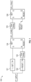
- FIG. 1 is a block diagram of an overcurrent protection logic 100 according to one or more embodiments described herein.
- the logic 100 sets an overcurrent condition (OC_COND) at block 104 when the generator current (CT_INPUT or "I") exceeds a defined set threshold (SET_TH) at block 101.
- the overcurrent fault (OC_FAULT) is then set at block 106 once the overcurrent condition has been present for a predefined time delay (time delay at block 105).
- overcurrent protection shown in FIG. 1 can be vulnerable to a system condition where currents repeatedly exceed the set threshold for less than the fault time delay and then drop below the reset threshold for longer than the reset threshold. If this configuration persists for an extended time, then the power source is susceptible to overheating and degradation due to usage beyond its intended limits, leading to a failure rate higher or quicker than expected.
- An example of this is a cyclical aircraft load that is applied on top of a higher-based load such as 90% of a rated load.
- the generator senses currents cyclically exceeding the overcurrent set threshold, and if the cycle on time of the load is less than the overcurrent fault time delay, then the generator is exceeding its intended capabilities and subject to degradation and potential early failures.
- TBC thermal circuit breaker
- a generator controller can perform residual overcurrent protection. Utilizing the generator controller provides for an aircraft airframer to reduce total component count and provide weight savings for the aircraft.
- Thermal conductivity is the property of a material to accumulate or dissipate heat over time.
- the conducting element will heat up and eventually activate when its thermal threshold is exceeded.
- the current is reduced before the TCB or fuse activates, then the conducting element will begin to cool without activating and opening the circuit. If this process repeats over time, and the duty cycle of the thermal threshold as exceeded is more than the ability of the conducting element to cool when the thermal threshold as not exceeded, then the TCB or fuse will be activated to protect the system.
- a timing variable is incremented at a defined rate ( I rate ) when the current is above the set threshold and not yet exceeding the overcurrent time delay.
- the same timing variable is decremented at a defined rate ( D rate ) when the current drops below the reset threshold and not yet exceeding the overcurrent time delay, with a minimum count of 0. If the current is oscillating between the set and reset thresholds but maintaining an average current rate above trip threshold, the fault is set when the residual of timer increments and decrements ( Count T ) has exceeded the defined fault time delay.
- FIG. 2 is a graph 200 showing a running residual count over time (1x-0.25x) according to one or more embodiments described herein.
- the graph 200 illustrates a trip curve where the running residual is increased at a 1x rate and decreased at a 0.25x rate.
- a loading pattern of an overload (increment) for 15 seconds followed by overload removal (decrement) for 20 seconds and a subsequent overload (increment) for 15 seconds results in the residual overcurrent protection activating in 50 seconds.
- FIG. 3 is a graph 300 showing a running residual count over time (1x-4x) according to one or more embodiments described herein.
- a cyclical loading pattern of an overload (increment) for 11 seconds followed by overload removal (decrement) for 2 seconds results in the residual overcurrent protection activating in 75 seconds.
- One or more embodiments described herein provides a highly customizable design that can replicate the environment into which the design is to be implemented. Thermal characteristics can be analyzed to design a robust implementation solution that is designed to minimize nuisances of the activation residual overcurrent protection while protecting the generator from long term exposure of fluctuating loads or intermittent downstream faults.
- FIG. 4A-4D together depict logic for residual overcurrent protection according to one or more embodiments described herein.
- Residual overcurrent protection is performed as follows. First, an increment amount ( FIG. 4A ) and a decrement amount ( FIG. 4B ) for residual overcurrent protection are determined. Next, based on the increment amount, the decrement amount, and a previous count value, a count value is determined ( FIG. 4C ). Using the count value and a residual over current limit, an overcurrent condition is detected ( FIG. 4D ), and a generator can be controlled to correct the overcurrent condition responsive to detecting the overcurrent condition (e.g., current can be reduced). Residual over current protection is now described in more detail with reference to FIGS. 4A-4D .
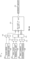
- FIG. 4A is a block diagram of an increment per clock cycle logic 400 for residual overcurrent protection according to one or more embodiments described herein.
- the logic 400 determines an increment amount 415 based on the following inputs: clock speed 401, increment rate 402, previous count 403 (also referred to as a "previous count value"), residual overcurrent limit 404, input current 405, and increment threshold 406.
- the clock speed 401 may be any suitable speed, such as substantially 5ms or less.
- the increment rate 402 defines the timing dynamics of the protection the value of the count at the previous clock cycle, referred to as the previous count 403.
- the residual overcurrent limit 404 is the number at which the protection will latch the fault.
- the input current 405 is sensed by the generator current transformers.
- the increment threshold 406 defines at what input current level the count variable should be counting up.
- the clock speed 401 and the increment rate 402 are multiplied by multiplier 410.
- the lesser (determined at block 411) of the previous count 403 and the residual overcurrent limit 404 is input into AND gate 413 as a first input, and the greater than or equal value (determined at block 412) between the input current 405 and the increment threshold 406 is input into the AND gate 413 as a second input.
- Outputs from the multiplier 410 and the AND gate 413 are input into inputs A and B, respectively, of logic block 414.
- the logic block 414 determines whether B is greater than 0. If so, the logic block 414 outputs A as the increment amount 415. If B is not greater than 0, a value (e.g., "0") received at an input C to the logic block 414 is output as the increment amount 415.
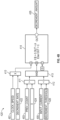
- FIG. 4B is a block diagram of a decrement per clock cycle logic 420 for residual overcurrent protection according to one or more embodiments described herein.
- the logic 420 determines a decrement amount 435 based on the following inputs: the clock speed 401, a decrement rate 422, the previous count 403, a constant value 424, the input current 405, and a decrement threshold 426.
- the decrement rate 422 defines the timing dynamics of how quickly the protection "cools off.”
- the constant value 424 can be any suitable value, such as "0" or another value.
- the decrement threshold 426 defines at what input current level the count variable should be counting down.
- the clock speed 401 and the decrement rate 422 are multiplied by multiplier 410.
- the greater (determined at block 411) of the previous count 403 and the constant value 424 is input into AND gate 413 as a first input, and the lesser value (determined at block 412) between the input current 405 and the decrement threshold 426 is input into the AND gate 413 as a second input.
- Outputs from the multiplier 410 and the AND gate 413 are input into inputs A and B, respectively, of logic block 414.
- the logic block 414 determines whether B is greater than 0. If so, the logic block 414 outputs A as the decrement amount 435. If B is not greater than 0, a value (e.g., "0") received at an input C to the logic block 414 is output as the decrement amount 435.
- the increment amount 415 ( FIG. 4A ) and the decrement amount 435 ( FIG. 4B ) can be used to determine a count 442 (also referred to as a "count value") as shown in FIG. 4C , which corresponds to equation 1 for calculating the count 442 as described above.
- FIG. 4C is a block diagram of a counter logic 440 for residual overcurrent protection according to one or more embodiments described herein.
- the count from the previous clock cycle e.g., the previous count 403 is summed with the increment amount 415 and the decrement amount 435 at adder 441. If the input current 405 is not greater than or equal to the increment threshold 406, then the increment amount 415 will be zero.
- the count 442 will increase by (clock speed 401) x (increment rate 402).
- the decrement amount 435 functions the same way such that if the input current 405 is greater than the decrement threshold 426, then the decrement amount 435 will be zero. If the input current 405 is less the decrement threshold 426, then the count 442 will be decreased by (clock speed 401) x (decrement rate 422). Also, the previous count 403 is updated using a 1-cycle delay 443.
- FIG. 4D a block diagram of an overcurrent fault logic 460 for residual overcurrent protection is shown according to one or more embodiments described herein.
- the count 442 is compared to the residual overcurrent limit 404 at block 461. If the count 442 is greater than or equal to the residual overcurrent limit 404, then the input is set to true for a reset-over-set type latch 462 to latch the overcurrent fault. The fault will remain "true” or “set” until the reset input (e.g., "reset switch") is set to true (e.g., a switch reset for an aircraft generator protection reset), at which point the overcurrent fault is set to "false” (un-latched).
- the generator controller can open the generator line contactor to remove power from the electrical system that was sourced by the generator experiencing the overload current. This action protects the electrical system that was sourced by the generator by eliminating the current overload, thus improving the operation of the aircraft by improving reliability.
- FIGS. 4A-4D encompasses the generator overcurrent protection design.
- the logic for an overcurrent protection illustrated in FIG. 1 where conventional overcurrent protection logic is captured within the residual overcurrent protection logic as the timer will increment to the residual overcurrent limit without decrementing.
- FIG. 5 is a graph 500 showing a running residual count over time with an overcurrent fault (no decrement) according to one or more embodiments described herein.
- an overload (increment) for 25 seconds without pause (no decrement) results in the residual overcurrent protection activating in 25 seconds, which is substantially the same as the response of an existing normal overcurrent protection.
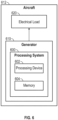
- FIG. 6 is a block diagram of an aircraft 612 according to one or more embodiments described herein.
- the aircraft 612 includes a generator 610 that generates electrical power and supplies electrical power to an electrical load 620.
- the generator 610 includes a processing system 600 (e.g., also referred to as a "controller” or “generator controller”). It is understood that one or more embodiments described herein is capable of being implemented in conjunction with any other type of computing environment now known or later developed.
- the processing system 600 can include a processing device 602, which may be one or more processing units. In aspects of the present disclosure, each processing unit can include a reduced instruction set computer (RISC) microprocessor.
- RISC reduced instruction set computer
- the processing device 602 can be a special-purpose processing device, such as application specific hardware, application specific integrated circuits (ASICs), application specific special processors (ASSPs), field programmable gate arrays (FPGAs), embedded controllers, hardwired circuitry, and/or the like, including combinations and/or multiples thereof.
- the processing device 602 can be coupled to memory 604, which can be any suitable type of memory device for storing data temporarily (e.g., random access memory (RAM)) and/or persistently (e.g., read only memory (RAM).
- RAM random access memory
- RAM read only memory
- the residual overcurrent protection described herein can be implemented using a combination of hardware and programming.
- the programming can be processor executable instructions stored on a tangible memory, and the hardware can include the processing device 602 for executing those instructions.
- a system memory e.g., memory 604
Landscapes
- Engineering & Computer Science (AREA)
- Power Engineering (AREA)
- Emergency Protection Circuit Devices (AREA)
Abstract
An example method for residual overcurrent protection includes determining an increment amount for residual overcurrent protection. The method further includes determining a decrement amount for residual overcurrent protection. The method further includes determining a count value based at least in part on the increment amount, the decrement amount, and a previous count value. The method further includes detecting an overcurrent condition based at least in part on the count value and a residual overcurrent limit. The method further includes controlling a generator (610) to correct the overcurrent condition responsive to detecting the overcurrent condition.Fig. 6
Description
- Embodiments described herein generally relate to aircraft, and more specifically, to residual overcurrent protection for a generator of an aircraft.
- An aircraft may include a generator (or multiple generators) that generate electrical power. The electrical power is distributed to different components and systems within an aircraft that consume the electrical power. Over current protection for a generator protects electrical loads and aircraft infrastructure from higher than expected currents.
- In one aspect, a method for residual overcurrent protection is provided. The method includes determining an increment amount for residual overcurrent protection. The method further includes determining a decrement amount for residual overcurrent protection. The method further includes determining a count value based at least in part on the increment amount, the decrement amount, and a previous count value. The method further includes detecting an overcurrent condition based at least in part on the count value and a residual overcurrent limit. The method further includes controlling a generator to correct the overcurrent condition responsive to detecting the overcurrent condition.
- Embodiments of the method may include that determining the increment amount is based at least in part on a clock speed, an increment rate, the previous count value, the residual overcurrent limit, an input current, and an increment threshold.
- Embodiments of the method may include that determining the decrement amount is based at least in part on a clock speed, a decrementing rate, the previous count value, a constant value, an input current, and a decrement threshold.
- Embodiments of the method may include that determining the count value further includes updating the previous count value using a one-cycle delay.
- Embodiments of the method may include that detecting the overcurrent condition includes comparing the count value and the residual overcurrent limit.
- Embodiments of the method may include, responsive to determining that the count value is greater than or equal to the residual overcurrent limit, setting an input of a reset-over-set type latch to true.
- Embodiments of the method may include resetting the reset-over-set type latch responsive to a reset input being set to true.
- In another aspect an aircraft is provided. The aircraft includes an electrical load and a generator to generate electrical power and supply the electrical power to the electrical load. The generator includes a controller. The controller determines an increment amount for residual overcurrent protection. The controller further determines determine a decrement amount for residual overcurrent protection. The controller further determines determine a count value based at least in part on the increment amount, the decrement amount, and a previous count value. The controller further detects an overcurrent condition based at least in part on the count value and a residual overcurrent limit. The controller further corrects the overcurrent condition responsive to detecting the overcurrent condition.
- Embodiments of the aircraft may include that determining the increment amount is based at least in part on a clock speed, an increment rate, the previous count value, the residual overcurrent limit, an input current, and an increment threshold.
- Embodiments of the aircraft may include that determining the decrement amount is based at least in part on a clock speed, a decrementing rate, the previous count value, a constant value, an input current, and a decrement threshold.
- Embodiments of the aircraft may include that determining the count value further includes updating the previous count value using a one-cycle delay.
- Embodiments of the aircraft may include that detecting the overcurrent condition includes comparing the count value and the residual overcurrent limit.
- Embodiments of the aircraft may include, responsive to determining that the count value is greater than or equal to the residual overcurrent limit, setting an input of a reset-over-set type latch to true.
- Embodiments of the aircraft may include resetting the reset-over-set type latch responsive to a reset input being set to true.
- In yet another aspect a controller is provided. The controller determines an increment amount for residual overcurrent protection. The controller further determines a decrement amount for residual overcurrent protection. The controller further determines a count value based at least in part on the increment amount, the decrement amount, and a previous count value. The controller further detects an overcurrent condition based at least in part on the count value and a residual overcurrent limit. The controller further corrects the overcurrent condition responsive to detecting the overcurrent condition.
- Embodiments of the controller may include that determining the increment amount is based at least in part on a clock speed, an increment rate, the previous count value, the residual overcurrent limit, an input current, and an increment threshold.
- Embodiments of the controller may include that determining the decrement amount is based at least in part on a clock speed, a decrementing rate, the previous count value, a constant value, an input current, and a decrement threshold.
- Embodiments of the controller may include that determining the count value further includes updating the previous count value using a one-cycle delay.
- Embodiments of the controller may include that detecting the overcurrent condition includes comparing the count value and the residual overcurrent limit.
- Embodiments of the controller may include, responsive to determining that the count value is greater than or equal to the residual overcurrent limit, setting an input of a reset-over-set type latch to true, and resetting the reset-over-set type latch responsive to a reset input being set to true.
- The above features and advantages, and other features and advantages, of the disclosure are readily apparent from the following detailed description when taken in connection with the accompanying drawings.
- The following descriptions are of examples only. The scope of the invention is as defined by the claims. With reference to the accompanying drawings, like elements are numbered alike:
-
FIG. 1 is a block diagram of an overcurrent protection logic according to one or more embodiments described herein; -
FIG. 2 is a graph showing a running residual count over time according to one or more embodiments described herein; -
FIG. 3 is a graph showing a running residual count over time according to one or more embodiments described herein; -
FIG. 4A is a block diagram of an increment per clock cycle logic for residual overcurrent protection according to one or more embodiments described herein; -
FIG. 4B is a block diagram of a decrement per clock cycle logic for residual overcurrent protection according to one or more embodiments described herein; -
FIG. 4C is a block diagram of a counter logic for residual overcurrent protection according to one or more embodiments described herein; -
FIG. 4D is a block diagram of an overcurrent fault logic for residual overcurrent protection according to one or more embodiments described herein; -
FIG. 5 is a graph showing a running residual count over time with an overcurrent fault (no decrement) according to one or more embodiments described herein; and -
FIG. 6 is a block diagram of an aircraft according to one or more embodiments described herein. - A detailed description of one or more embodiments of the disclosed apparatus and method are presented herein by way of exemplification and not limitation with reference to the Figures.
- One or more embodiments described herein provide for residual overcurrent protection, for example, for a generator of an aircraft. Over current protection for a generator protects electrical loads and aircraft infrastructure from higher than expected currents. A generator overcurrent (OC) protection function uses current inputs monitored by generator current transformers (CTs).
- From a systems architecture and design perspective, the failures and aircraft conditions that can cause a generator OC fault can include: loads applied can exceed source capability, which can be caused by improper load management (automated or pilot induced) and/or another generator in the system being tripped/failed causing the remaining generator(s) to source additional loads; a generator control unit (GCU) or controller issue, such as a sense circuit error, measurement error, and/or the like, including combinations and/or multiples thereof; and/or a "low" impedance fault in an unprotected area (e.g., not in a differential protection zone).
- One approach to overcurrent protection is shown in
FIG. 1 . Particularly,FIG. 1 is a block diagram of anovercurrent protection logic 100 according to one or more embodiments described herein. In this example, thelogic 100 sets an overcurrent condition (OC_COND) atblock 104 when the generator current (CT_INPUT or "I") exceeds a defined set threshold (SET_TH) atblock 101. The overcurrent fault (OC_FAULT) is then set atblock 106 once the overcurrent condition has been present for a predefined time delay (time delay at block 105). If the current (CT_INPUT or "I") drops below a reset threshold (RESET_TH) atblock 102 for a specified amount of time (time delay 103), the overcurrent condition (OC_COND) is reset atblock 104 and the process repeats. - The type of overcurrent protection shown in
FIG. 1 can be vulnerable to a system condition where currents repeatedly exceed the set threshold for less than the fault time delay and then drop below the reset threshold for longer than the reset threshold. If this configuration persists for an extended time, then the power source is susceptible to overheating and degradation due to usage beyond its intended limits, leading to a failure rate higher or quicker than expected. An example of this is a cyclical aircraft load that is applied on top of a higher-based load such as 90% of a rated load. If the cyclical load is 20% of the rated load, then the generator senses currents cyclically exceeding the overcurrent set threshold, and if the cycle on time of the load is less than the overcurrent fault time delay, then the generator is exceeding its intended capabilities and subject to degradation and potential early failures. - One possible solution is to implement a thermal circuit breaker (TCB) or a fuse; however, each of these approaches has its own inherent challenges and adds to the overall part count of the system.
- According to one or more embodiments described herein, a generator controller can perform residual overcurrent protection. Utilizing the generator controller provides for an aircraft airframer to reduce total component count and provide weight savings for the aircraft.
- According to one or more embodiments described herein, residual over current protection is implemented based on the dynamics of thermal conductivity. Thermal conductivity is the property of a material to accumulate or dissipate heat over time. In a traditional device, when a high current passes through a TCB or a fuse, the conducting element will heat up and eventually activate when its thermal threshold is exceeded. However, if the current is reduced before the TCB or fuse activates, then the conducting element will begin to cool without activating and opening the circuit. If this process repeats over time, and the duty cycle of the thermal threshold as exceeded is more than the ability of the conducting element to cool when the thermal threshold as not exceeded, then the TCB or fuse will be activated to protect the system.
- Similarly, residual overcurrent protection makes the fault time a function of the rate of time spent above a set threshold minus the rate of time spent below a reset threshold. This functionality is accomplished in the following way according to one or more embodiments. A timing variable is incremented at a defined rate (Irate ) when the current is above the set threshold and not yet exceeding the overcurrent time delay. The same timing variable is decremented at a defined rate (Drate ) when the current drops below the reset threshold and not yet exceeding the overcurrent time delay, with a minimum count of 0. If the current is oscillating between the set and reset thresholds but maintaining an average current rate above trip threshold, the fault is set when the residual of timer increments and decrements (CountT ) has exceeded the defined fault time delay. The timing variable can be expressed mathematically via the following formulae (1), (2), and (3):


- Modeling the conductive properties of a TCB or fuse lies in the rate at which the timers are incremented and decremented. By causing the incrementing rate to be greater than the decrementing rate, the dynamics of a circuit that heats up quickly and cools off slowly can be replicated, as shown in
FIG. 2 . Particularly,FIG. 2 is agraph 200 showing a running residual count over time (1x-0.25x) according to one or more embodiments described herein. Thegraph 200 illustrates a trip curve where the running residual is increased at a 1x rate and decreased at a 0.25x rate. In this example, a loading pattern of an overload (increment) for 15 seconds followed by overload removal (decrement) for 20 seconds and a subsequent overload (increment) for 15 seconds results in the residual overcurrent protection activating in 50 seconds. - If the cooler element has high capabilities, such as a generator in an oil-cooled circuit environment, then the running residual thermal characteristics may be biased in a reversed direction where the running residual is increased at a 1x rate and decreased at a 4x rate, as shown in
FIG. 3 . Particularly,FIG. 3 is agraph 300 showing a running residual count over time (1x-4x) according to one or more embodiments described herein. In this example, a cyclical loading pattern of an overload (increment) for 11 seconds followed by overload removal (decrement) for 2 seconds results in the residual overcurrent protection activating in 75 seconds. - One or more embodiments described herein provides a highly customizable design that can replicate the environment into which the design is to be implemented. Thermal characteristics can be analyzed to design a robust implementation solution that is designed to minimize nuisances of the activation residual overcurrent protection while protecting the generator from long term exposure of fluctuating loads or intermittent downstream faults.
-
FIG. 4A-4D together depict logic for residual overcurrent protection according to one or more embodiments described herein. Residual overcurrent protection is performed as follows. First, an increment amount (FIG. 4A ) and a decrement amount (FIG. 4B ) for residual overcurrent protection are determined. Next, based on the increment amount, the decrement amount, and a previous count value, a count value is determined (FIG. 4C ). Using the count value and a residual over current limit, an overcurrent condition is detected (FIG. 4D ), and a generator can be controlled to correct the overcurrent condition responsive to detecting the overcurrent condition (e.g., current can be reduced). Residual over current protection is now described in more detail with reference toFIGS. 4A-4D . -
FIG. 4A is a block diagram of an increment perclock cycle logic 400 for residual overcurrent protection according to one or more embodiments described herein. Thelogic 400 determines anincrement amount 415 based on the following inputs:clock speed 401,increment rate 402, previous count 403 (also referred to as a "previous count value"),residual overcurrent limit 404, input current 405, andincrement threshold 406. Theclock speed 401 may be any suitable speed, such as substantially 5ms or less. Theincrement rate 402 defines the timing dynamics of the protection the value of the count at the previous clock cycle, referred to as theprevious count 403. Theresidual overcurrent limit 404 is the number at which the protection will latch the fault. The input current 405 is sensed by the generator current transformers. Theincrement threshold 406 defines at what input current level the count variable should be counting up. - As shown in
FIG. 4A , theclock speed 401 and theincrement rate 402 are multiplied bymultiplier 410. The lesser (determined at block 411) of theprevious count 403 and theresidual overcurrent limit 404 is input into ANDgate 413 as a first input, and the greater than or equal value (determined at block 412) between the input current 405 and theincrement threshold 406 is input into the ANDgate 413 as a second input. Outputs from themultiplier 410 and the ANDgate 413 are input into inputs A and B, respectively, oflogic block 414. Thelogic block 414 determines whether B is greater than 0. If so, thelogic block 414 outputs A as theincrement amount 415. If B is not greater than 0, a value (e.g., "0") received at an input C to thelogic block 414 is output as theincrement amount 415. -
FIG. 4B is a block diagram of a decrement perclock cycle logic 420 for residual overcurrent protection according to one or more embodiments described herein. Thelogic 420 determines adecrement amount 435 based on the following inputs: theclock speed 401, adecrement rate 422, theprevious count 403, aconstant value 424, the input current 405, and adecrement threshold 426. Thedecrement rate 422 defines the timing dynamics of how quickly the protection "cools off." Theconstant value 424 can be any suitable value, such as "0" or another value. Thedecrement threshold 426 defines at what input current level the count variable should be counting down. - As shown in
FIG. 4B , theclock speed 401 and thedecrement rate 422 are multiplied bymultiplier 410. The greater (determined at block 411) of theprevious count 403 and theconstant value 424 is input into ANDgate 413 as a first input, and the lesser value (determined at block 412) between the input current 405 and thedecrement threshold 426 is input into the ANDgate 413 as a second input. Outputs from themultiplier 410 and the ANDgate 413 are input into inputs A and B, respectively, oflogic block 414. Thelogic block 414 determines whether B is greater than 0. If so, thelogic block 414 outputs A as thedecrement amount 435. If B is not greater than 0, a value (e.g., "0") received at an input C to thelogic block 414 is output as thedecrement amount 435. - The increment amount 415 (
FIG. 4A ) and the decrement amount 435 (FIG. 4B ) can be used to determine a count 442 (also referred to as a "count value") as shown inFIG. 4C , which corresponds toequation 1 for calculating thecount 442 as described above. Particularly,FIG. 4C is a block diagram of acounter logic 440 for residual overcurrent protection according to one or more embodiments described herein. The count from the previous clock cycle (e.g., the previous count 403) is summed with theincrement amount 415 and thedecrement amount 435 atadder 441. If the input current 405 is not greater than or equal to theincrement threshold 406, then theincrement amount 415 will be zero. If the input current 405 is above theincrement threshold 406, then thecount 442 will increase by (clock speed 401) x (increment rate 402). Thedecrement amount 435 functions the same way such that if the input current 405 is greater than thedecrement threshold 426, then thedecrement amount 435 will be zero. If the input current 405 is less thedecrement threshold 426, then thecount 442 will be decreased by (clock speed 401) x (decrement rate 422). Also, theprevious count 403 is updated using a 1-cycle delay 443. - Turning now to
FIG. 4D , a block diagram of anovercurrent fault logic 460 for residual overcurrent protection is shown according to one or more embodiments described herein. - The
count 442 is compared to theresidual overcurrent limit 404 atblock 461. If thecount 442 is greater than or equal to theresidual overcurrent limit 404, then the input is set to true for a reset-over-set type latch 462 to latch the overcurrent fault. The fault will remain "true" or "set" until the reset input (e.g., "reset switch") is set to true (e.g., a switch reset for an aircraft generator protection reset), at which point the overcurrent fault is set to "false" (un-latched). When an overcurrent fault occurs, the generator controller can open the generator line contactor to remove power from the electrical system that was sourced by the generator experiencing the overload current. This action protects the electrical system that was sourced by the generator by eliminating the current overload, thus improving the operation of the aircraft by improving reliability. - In addition to providing protection from short repeated overcurrent conditions, the residual overcurrent protection logic shown in
FIGS. 4A-4D encompasses the generator overcurrent protection design. The logic for an overcurrent protection illustrated inFIG. 1 , where conventional overcurrent protection logic is captured within the residual overcurrent protection logic as the timer will increment to the residual overcurrent limit without decrementing. An illustration for this scenario is shown inFIG. 5 . Particularly,FIG. 5 is agraph 500 showing a running residual count over time with an overcurrent fault (no decrement) according to one or more embodiments described herein. In this example, an overload (increment) for 25 seconds without pause (no decrement) results in the residual overcurrent protection activating in 25 seconds, which is substantially the same as the response of an existing normal overcurrent protection. -
FIG. 6 is a block diagram of anaircraft 612 according to one or more embodiments described herein. Theaircraft 612 includes agenerator 610 that generates electrical power and supplies electrical power to anelectrical load 620. Thegenerator 610 includes a processing system 600 (e.g., also referred to as a "controller" or "generator controller"). It is understood that one or more embodiments described herein is capable of being implemented in conjunction with any other type of computing environment now known or later developed. Theprocessing system 600 can include aprocessing device 602, which may be one or more processing units. In aspects of the present disclosure, each processing unit can include a reduced instruction set computer (RISC) microprocessor. As another example, theprocessing device 602 can be a special-purpose processing device, such as application specific hardware, application specific integrated circuits (ASICs), application specific special processors (ASSPs), field programmable gate arrays (FPGAs), embedded controllers, hardwired circuitry, and/or the like, including combinations and/or multiples thereof. Theprocessing device 602 can be coupled tomemory 604, which can be any suitable type of memory device for storing data temporarily (e.g., random access memory (RAM)) and/or persistently (e.g., read only memory (RAM). According to aspects of the present disclosure, the residual overcurrent protection described herein can be implemented using a combination of hardware and programming. The programming can be processor executable instructions stored on a tangible memory, and the hardware can include theprocessing device 602 for executing those instructions. Thus a system memory (e.g., memory 604) can store program instructions that when executed by theprocessing device 602 implement the residual overcurrent protection described herein. - The term "about" is intended to include the degree of error associated with measurement of the particular quantity based upon the equipment available at the time of filing the application.
- The terminology used herein is for the purpose of describing particular embodiments only and is not intended to be limiting of the present disclosure. As used herein, the singular forms "a", "an" and "the" are intended to include the plural forms as well, unless the context clearly indicates otherwise. It will be further understood that the terms "comprises" and/or "comprising," when used in this specification, specify the presence of stated features, integers, steps, operations, elements, and/or components, but do not preclude the presence or addition of one or more other features, integers, steps, operations, element components, and/or groups thereof.
- While the present disclosure has been described with reference to an exemplary embodiment or embodiments, it will be understood by those skilled in the art that various changes may be made without departing from the scope of the invention as defined by the claims. In addition, many modifications may be made to adapt a particular situation or material to the teachings of the present disclosure without departing from the scope of the claims. Therefore, it is intended that the present disclosure not be limited to the particular embodiment disclosed as the best mode contemplated for carrying out this present disclosure, but that the present disclosure will include all embodiments falling within the scope of the claims.
Claims (9)
- A method for residual overcurrent protection comprising:determining an increment amount for residual overcurrent protection;determining a decrement amount for residual overcurrent protection;determining a count value based at least in part on the increment amount, the decrement amount, and a previous count value;detecting an overcurrent condition based at least in part on the count value and a residual overcurrent limit; andcontrolling a generator to correct the overcurrent condition responsive to detecting the overcurrent condition.
- The method of claim 1, wherein determining the increment amount is based at least in part on a clock speed, an increment rate, the previous count value, the residual overcurrent limit, an input current, and an increment threshold.
- The method of claim 1 or 2, wherein determining the decrement amount is based at least in part on a clock speed, a decrementing rate, the previous count value, a constant value, an input current, and a decrement threshold.
- The method of any preceding claim, wherein determining the count value further comprises updating the previous count value using a one-cycle delay.
- The method of any preceding claim, wherein detecting the overcurrent condition comprises comparing the count value and the residual overcurrent limit.
- The method of claim 5, further comprising, responsive to determining that the count value is greater than or equal to the residual overcurrent limit, setting an input of a reset-over-set type latch to true.
- The method of claim 6, further comprising resetting the reset-over-set type latch responsive to a reset input being set to true.
- A controller configured to:
perform the method of any preceding claim.. - An aircraft comprising:an electrical load (620); anda generator (610) to generate electrical power and supply the electrical power to the electrical load, the generator comprising a controller configured to perform the method of any of claims 1 to 7.
Applications Claiming Priority (1)
| Application Number | Priority Date | Filing Date | Title |
|---|---|---|---|
| US18/073,901 US20240186784A1 (en) | 2022-12-02 | 2022-12-02 | Residual overcurrent protection |
Publications (1)
| Publication Number | Publication Date |
|---|---|
| EP4387024A1 true EP4387024A1 (en) | 2024-06-19 |
Family
ID=89073366
Family Applications (1)
| Application Number | Title | Priority Date | Filing Date |
|---|---|---|---|
| EP23213763.8A Pending EP4387024A1 (en) | 2022-12-02 | 2023-12-01 | Residual overcurrent protection |
Country Status (2)
| Country | Link |
|---|---|
| US (1) | US20240186784A1 (en) |
| EP (1) | EP4387024A1 (en) |
Citations (2)
| Publication number | Priority date | Publication date | Assignee | Title |
|---|---|---|---|---|
| CA2045043A1 (en) * | 1990-07-03 | 1992-01-04 | Paul Tripodi | Electronic trip device comprising an improved long delay function |
| US20180294643A1 (en) * | 2017-04-07 | 2018-10-11 | Infineon Technologies Ag | Circuit and Method of Over-Current Protection |
Family Cites Families (4)
| Publication number | Priority date | Publication date | Assignee | Title |
|---|---|---|---|---|
| US5471359A (en) * | 1993-02-25 | 1995-11-28 | Impco Inc. | Polyphase current monitor and control system |
| US9147546B2 (en) * | 2011-11-30 | 2015-09-29 | Veris Industries, Llc | Self-calibrating current switch with display |
| IT201900002297A1 (en) * | 2019-02-18 | 2020-08-18 | St Microelectronics Srl | PROTECTION CIRCUIT, SYSTEM AND CORRESPONDING PROCEDURE |
| US12199422B2 (en) * | 2021-04-02 | 2025-01-14 | Hamilton Sundstrand Corporation | Systems and methods for overcurrent protection |
-
2022
- 2022-12-02 US US18/073,901 patent/US20240186784A1/en not_active Abandoned
-
2023
- 2023-12-01 EP EP23213763.8A patent/EP4387024A1/en active Pending
Patent Citations (2)
| Publication number | Priority date | Publication date | Assignee | Title |
|---|---|---|---|---|
| CA2045043A1 (en) * | 1990-07-03 | 1992-01-04 | Paul Tripodi | Electronic trip device comprising an improved long delay function |
| US20180294643A1 (en) * | 2017-04-07 | 2018-10-11 | Infineon Technologies Ag | Circuit and Method of Over-Current Protection |
Also Published As
| Publication number | Publication date |
|---|---|
| US20240186784A1 (en) | 2024-06-06 |
Similar Documents
| Publication | Publication Date | Title |
|---|---|---|
| EP3723225B1 (en) | Selective coordination of solid-state circuit breakers and mechanical circuit breakers in electrical distribution systems | |
| EP2544353A1 (en) | Inverter and overload protection method | |
| US20140055903A1 (en) | Fast breaker failure detection for hvdc circuit breakers | |
| DE102017222475B4 (en) | Inrush Current Prevention Circuit, Inrush Current Prevention Method And Inrush Current Prevention Program | |
| JP2003100196A (en) | Electronic circuit breaker | |
| US20080180196A1 (en) | Electronic trip unit for circuit breakers | |
| JP6386579B2 (en) | Power control apparatus and power control system including the same | |
| EP2842210B1 (en) | Switching circuit protector | |
| US11652346B2 (en) | Systems and methods for input overcurrent protection | |
| JP6359957B2 (en) | Motor drive device having secondary damage prevention function | |
| US8659856B2 (en) | DC arc fault detection and protection | |
| EP4387024A1 (en) | Residual overcurrent protection | |
| US4951250A (en) | Combined input/output circuit for a programmable controller | |
| CN102763297B (en) | Method for monitoring classification margins between time-current characteristics of intelligent electronic devices | |
| KR20130131109A (en) | Adaptive protection overcurrent control system and method for responding the change of power system | |
| CN109936120A (en) | Inverter management method and system | |
| US11418021B2 (en) | Device circuit breaker having intelligent limit value determination and method therefor | |
| KR102180549B1 (en) | Protection method and apparatus for high resistance ground fault detection | |
| EP2110917A2 (en) | Method of setting a ground fault trip function for a trip unit and a trip unit having a defined trip function for ground fault protection | |
| WO2014162874A1 (en) | Cutoff device | |
| CN114080740B (en) | Resettable electronic fuses for high power devices | |
| CN108604520B (en) | Method and apparatus for protecting electrical architecture | |
| JP5030713B2 (en) | Short-circuit accident detection relay | |
| EP3016258B1 (en) | Apparatus and method for protecting grid-connected inverter from occurrence of low grid voltage | |
| CN112018897B (en) | Method and device for monitoring state of superconducting AC current limiter based on reclosing |
Legal Events
| Date | Code | Title | Description |
|---|---|---|---|
| PUAI | Public reference made under article 153(3) epc to a published international application that has entered the european phase |
Free format text: ORIGINAL CODE: 0009012 |
|
| STAA | Information on the status of an ep patent application or granted ep patent |
Free format text: STATUS: THE APPLICATION HAS BEEN PUBLISHED |
|
| AK | Designated contracting states |
Kind code of ref document: A1 Designated state(s): AL AT BE BG CH CY CZ DE DK EE ES FI FR GB GR HR HU IE IS IT LI LT LU LV MC ME MK MT NL NO PL PT RO RS SE SI SK SM TR |
|
| STAA | Information on the status of an ep patent application or granted ep patent |
Free format text: STATUS: REQUEST FOR EXAMINATION WAS MADE |
|
| 17P | Request for examination filed |
Effective date: 20241218 |