EP4387018A1 - Switchgear current transformer replacement system - Google Patents
Switchgear current transformer replacement system Download PDFInfo
- Publication number
- EP4387018A1 EP4387018A1 EP22213716.8A EP22213716A EP4387018A1 EP 4387018 A1 EP4387018 A1 EP 4387018A1 EP 22213716 A EP22213716 A EP 22213716A EP 4387018 A1 EP4387018 A1 EP 4387018A1
- Authority
- EP
- European Patent Office
- Prior art keywords
- rails
- rail
- current transformer
- switchgear
- truck
- Prior art date
- Legal status (The legal status is an assumption and is not a legal conclusion. Google has not performed a legal analysis and makes no representation as to the accuracy of the status listed.)
- Pending
Links
Images




Classifications
-
- H—ELECTRICITY
- H02—GENERATION; CONVERSION OR DISTRIBUTION OF ELECTRIC POWER
- H02B—BOARDS, SUBSTATIONS OR SWITCHING ARRANGEMENTS FOR THE SUPPLY OR DISTRIBUTION OF ELECTRIC POWER
- H02B1/00—Frameworks, boards, panels, desks, casings; Details of substations or switching arrangements
- H02B1/015—Boards, panels, desks; Parts thereof or accessories therefor
- H02B1/04—Mounting thereon of switches or of other devices in general, the switch or device having, or being without, casing
- H02B1/052—Mounting on rails
-
- H—ELECTRICITY
- H02—GENERATION; CONVERSION OR DISTRIBUTION OF ELECTRIC POWER
- H02B—BOARDS, SUBSTATIONS OR SWITCHING ARRANGEMENTS FOR THE SUPPLY OR DISTRIBUTION OF ELECTRIC POWER
- H02B3/00—Apparatus specially adapted for the manufacture, assembly, or maintenance of boards or switchgear
-
- H—ELECTRICITY
- H02—GENERATION; CONVERSION OR DISTRIBUTION OF ELECTRIC POWER
- H02B—BOARDS, SUBSTATIONS OR SWITCHING ARRANGEMENTS FOR THE SUPPLY OR DISTRIBUTION OF ELECTRIC POWER
- H02B11/00—Switchgear having carriage withdrawable for isolation
- H02B11/12—Switchgear having carriage withdrawable for isolation with isolation by horizontal withdrawal
- H02B11/167—Switchgear having carriage withdrawable for isolation with isolation by horizontal withdrawal truck type
-
- H—ELECTRICITY
- H02—GENERATION; CONVERSION OR DISTRIBUTION OF ELECTRIC POWER
- H02B—BOARDS, SUBSTATIONS OR SWITCHING ARRANGEMENTS FOR THE SUPPLY OR DISTRIBUTION OF ELECTRIC POWER
- H02B13/00—Arrangement of switchgear in which switches are enclosed in, or structurally associated with, a casing, e.g. cubicle
- H02B13/02—Arrangement of switchgear in which switches are enclosed in, or structurally associated with, a casing, e.g. cubicle with metal casing
- H02B13/035—Gas-insulated switchgear
- H02B13/0356—Mounting of monitoring devices, e.g. current transformers
Definitions
- the present invention relates to switchgear current transformer replacement systems and switchgear current transformer replacement methods.
- a switchgear current transformer replacement system comprising:
- a truck system can be placed on and moved along existing rails in a compartment of a switchgear in a first direction in order to move up to a current transformer in the compartment.
- the truck system can then connect to the current transformer in order to extract the current transformer by moving the truck system in a second direction opposite to the first direction.
- a simple means is provided to help replace current transformers in a switchgear compartment that only requires one side of the compartment to be opened, reducing the time to replace current transformers, reducing the chance of injury, and saving costs and work and downtime considerably.
- the one or more rails of the rail system comprises at least two rails parallel to each other.
- the truck system comprises one or more wheels that are configured to roll along the one or rails of the rail system.
- the truck system comprises two or more wheels, wherein at least one wheel is configured to roll along a first rail of the at least two rails and at least one wheel is configured to roll along a second rail of the at least two rails.
- At least two wheels of the truck system are configured to roll along the first rail of the at least two rails and at least two wheels of the truck system are configured to roll along the second rail of the at least two rails.
- the truck system can be easily placed on or engaged with the rail(s) of the rail system, and easily moved forward and backwards along the rail(s) to extract a current transformer, and then replace the current transformer with a new unit.
- the truck system when engaged with the one or more rails of the rail system is configured to move the connection section in at least one direction perpendicular to the one or more rails of the rail system.
- the truck system is configured to move the connection section of the truck system in a direction parallel to a direction extending from a first rail of the one or more rails to a second rail of the one or more rails, and wherein the truck system is configured to move the connection section of the truck system in a direction perpendicular to the direction extending from the first rail of the one or more rails to the second rail of the one or more rails.
- the truck system can be accurately aligned with a current transformer in order to remove it from the compartment, and indeed the truck system can also be aligned with each current transformer for each phase of a three phase system enabling the current transformer for any of the phases to be replaced.
- a switchgear current transformer replacement system comprising:
- a special set of rails can be mounted to a compartment of a switchgear, for example at locations of circuit breaker rails.
- a truck system can moved along the rails in a first direction in order to move up to a current transformer in the compartment.
- the truck system can then connect to the current transformer in order to extract the current transformer by moving the truck system in a second direction opposite to the first direction.
- a simple means is provided to help replace current transformers in a switchgear compartment that only requires one side of the compartment to be opened, reducing the time to replace current transformers, reducing the chance of injury, and saving costs and work and downtime considerably.
- the rails can then be removed from the compartment.
- the truck system is configured to engage with the one or more rails of the rail system of the compartment of the switchgear prior to moving the truck system along the one or more rails of the rail system.
- the rail system that is mounted to the compartment of the switchgear can have a truck system integrated with it, or the truck system can be separate to the rail system.
- the new system can be utilized with existing switchgear and their compartments in that the rail(s) are mounted to the existing compartments.
- existing rails of switchgear can be utilized, such as circuit breaker tracks or rails in certain situations, or new switchgear compartments can be manufactured with rail(s) of the new system already present with the compartment that will house current transformers.
- the one or more rails of the rail system comprises at least two rails parallel to each other.
- the truck system comprises one or more wheels that are configured to roll along the one or rails of the rail system.
- the truck system comprises two or more wheels, wherein at least one wheel is configured to roll along a first rail of the at least two rails and at least one wheel is configured to roll along a second rail of the at least two rails.
- At least two wheels of the truck system are configured to roll along the first rail of the at least two rails and at least two wheels of the truck system are configured to roll along the second rail of the at least two rails.
- the truck system when engaged with the one or more rails of the rail system is configured to move the connection section in at least one direction perpendicular to the one or more rails of the rail system.
- the truck system is configured to move the connection section of the truck system in a direction parallel to a direction extending from a first rail of the one or more rails to a second rail of the one or more rails, and the truck system is configured to move the connection section of the truck system in a direction perpendicular to the direction extending from the first rail of the one or more rails to the second rail of the one or more rails.
- a switchgear current transformer replacement method comprising:
- the one or more rails of the rail system comprises at least two rails parallel to each other.
- the truck system comprises one or more wheels that are configured to roll along the one or rails of the rail system.
- the truck system comprises two or more wheels, wherein at least one wheel is configured to roll along a first rail of the at least two rails and at least one wheel is configured to roll along a second rail of the at least two rails.
- At least two wheels of the truck system are configured to roll along the first rail of the at least two rails and at least two wheels of the truck system are configured to roll along the second rail of the at least two rails.
- the method comprises moving the connection section in at least one direction perpendicular to the one or more rails of the rail system.
- the method comprises moving the connection section of the truck system in a direction parallel to a direction extending from a first rail of the one or more rails to a second rail of the one or more rails.
- the method comprises moving the connection section of the truck system in a direction perpendicular to the direction extending from the first rail of the one or more rails to the second rail of the one or more rails.
- a switchgear current transformer replacement method comprising:
- the method comprises engaging the truck system with the one or more rails of the rail system of the compartment of the switchgear prior to moving the truck system along the one or more rails of the rail system.
- the one or more rails of the rail system comprises at least two rails parallel to each other.
- the truck system comprises one or more wheels that are configured to roll along the one or rails of the rail system.
- the truck system comprises two or more wheels, wherein at least one wheel is configured to roll along a first rail of the at least two rails and at least one wheel is configured to roll along a second rail of the at least two rails.
- At least two wheels of the truck system are configured to roll along the first rail of the at least two rails and at least two wheels of the truck system are configured to roll along the second rail of the at least two rails.
- the method comprises moving the connection section in at least one direction perpendicular to the one or more rails of the rail system.
- the method comprises moving the connection section of the truck system in a direction parallel to a direction extending from a first rail of the one or more rails to a second rail of the one or more rails.
- the method comprises moving the connection section of the truck system in a direction perpendicular to the direction extending from the first rail of the one or more rails to the second rail of the one or more rails.
- Fig. 1 shows a sideview of a switchgear compartment with an arrow showing how a current transformer is to be removed from the compartment, where the current transformer is located at the rear of the arrow.
- Figs. 2-8 relate to the new switchgear current transformer replacement systems and the new switchgear current transformer replacement methods.
- a switchgear current transformer replacement system comprises a truck system.
- the truck system comprises a connection section.
- the truck system is configured to engage with and move along one or more rails of a rail system of a compartment of a switchgear.
- the connection section of the truck system is configured to connect to a current transformer.
- the truck system when engaged with the one or more rails of the rail system is configured to move along the one or more rails of the rail system to a position adjacent to the current transformer at its operational location within the compartment of the switchgear.
- the connection section of the truck system is configured to connect to the current transformer.
- truck system When the truck system is connected to the current transformer, and when the truck system is engaged with the one or more rails of the rail system and when the connection section is connected to the current transformer the truck system is configured to move along the one or more rails of the rail system with the current transformer to move the current transformer away from its operational location within the compartment of the switchgear.
- a truck system can be placed on and moved along existing rails in a compartment of a switchgear in a first direction in order to move up to a current transformer in the compartment.
- the truck system can then connect to the current transformer in order to extract the current transformer by moving the truck system in a second direction opposite to the first direction.
- a simple means is provided to help replace current transformers in a switchgear compartment that only requires one side of the compartment to be opened.
- the one or more rails of the rail system comprises at least two rails parallel to each other.
- the truck system comprises one or more wheels that are configured to roll along the one or rails of the rail system.
- the truck system comprises two or more wheels, wherein at least one wheel is configured to roll along a first rail of the at least two rails and at least one wheel is configured to roll along a second rail of the at least two rails.
- At least two wheels of the truck system are configured to roll along the first rail of the at least two rails and at least two wheels of the truck system are configured to roll along the second rail of the at least two rails.
- the truck system can be easily placed on or engaged with the rail(s) of the rail system, and easily moved forward and backwards along the rail(s) to extract a current transformer, and then replace the current transformer with a new unit.
- the truck system when engaged with the one or more rails of the rail system is configured to move the connection section in at least one direction perpendicular to the one or more rails of the rail system.
- the truck system is configured to move the connection section of the truck system in a direction parallel to a direction extending from a first rail of the one or more rails to a second rail of the one or more rails, and wherein the truck system is configured to move the connection section of the truck system in a direction perpendicular to the direction extending from the first rail of the one or more rails to the second rail of the one or more rails.
- the truck system can be accurately aligned with a current transformer in order to remove it from the compartment, and indeed the truck system can also be aligned with each current transformer for each phase of a three phase system enabling the current transformer for any of the phases to be replaced.
- a switchgear current transformer replacement system comprises a rail system, and a truck system.
- the rail system is configured to be mounted to a compartment of a switchgear.
- the rail system comprises one or more rails.
- the truck system comprises a connection section.
- the truck system is configured to move along the one or more rails of the rail system.
- the connection section of the truck system is configured to connect to a current transformer.
- the truck system is mounted to the compartment of the switchgear, the truck system is configured to move along the one or more rails of the rail system to a position adjacent to the current transformer at its operational location within the compartment of the switchgear.
- the connection section of the truck system is configured to connect to the current transformer.
- the truck system When the truck system is connected to the current transformer, and when the connection section is connected to the current transformer, the truck system is configured to move along the one or more rails of the rail system with the current transformer to move the current transformer away from its operational location within the compartment of the switchgear.
- a special set of rails can be mounted to a compartment of a switchgear, for example at locations of circuit breaker rails or tracks.
- a truck system can moved along the rails in a first direction in order to move up to a current transformer in the compartment.
- the truck system can then connect to the current transformer in order to extract the current transformer by moving the truck system in a second direction opposite to the first direction.
- a simple means is provided to help replace current transformers in a switchgear compartment that only requires one side of the compartment to be opened, reducing the time to replace current transformers, and saving costs and work and downtime considerably.
- the rails can then be removed from the compartment.
- the truck system is configured to engage with the one or more rails of the rail system of the compartment of the switchgear prior to moving the truck system along the one or more rails of the rail system.
- the rail system that is mounted to the compartment of the switchgear can have a truck system integrated with it, or the truck system can be separate to the rail system.
- the new system can be utilized with existing switchgear and their compartments in that the rail(s) are mounted to the existing compartments.
- existing rails of switchgear can be utilized, such as circuit breaker rails in certain situations, or new switchgear compartments can be manufactured with rail(s) of the new system already present with the compartment that will house current transformers.
- the one or more rails of the rail system comprises at least two rails parallel to each other.
- the truck system comprises one or more wheels that are configured to roll along the one or rails of the rail system.
- the truck system comprises two or more wheels, wherein at least one wheel is configured to roll along a first rail of the at least two rails and at least one wheel is configured to roll along a second rail of the at least two rails.
- At least two wheels of the truck system are configured to roll along the first rail of the at least two rails and at least two wheels of the truck system are configured to roll along the second rail of the at least two rails.
- the truck system when engaged with the one or more rails of the rail system is configured to move the connection section in at least one direction perpendicular to the one or more rails of the rail system.
- the truck system is configured to move the connection section of the truck system in a direction parallel to a direction extending from a first rail of the one or more rails to a second rail of the one or more rails, and the truck system is configured to move the connection section of the truck system in a direction perpendicular to the direction extending from the first rail of the one or more rails to the second rail of the one or more rails.
- a switchgear current transformer replacement method comprises
- the one or more rails of the rail system comprises at least two rails parallel to each other.
- the truck system comprises one or more wheels that are configured to roll along the one or rails of the rail system.
- the truck system comprises two or more wheels, wherein at least one wheel is configured to roll along a first rail of the at least two rails and at least one wheel is configured to roll along a second rail of the at least two rails.
- At least two wheels of the truck system are configured to roll along the first rail of the at least two rails and at least two wheels of the truck system are configured to roll along the second rail of the at least two rails.
- the method comprises moving the connection section in at least one direction perpendicular to the one or more rails of the rail system.
- the method comprises moving the connection section of the truck system in a direction parallel to a direction extending from a first rail of the one or more rails to a second rail of the one or more rails.
- the method comprises moving the connection section of the truck system in a direction perpendicular to the direction extending from the first rail of the one or more rails to the second rail of the one or more rails.
- a switchgear current transformer replacement method comprises:
- the method comprises engaging the truck system with the one or more rails of the rail system of the compartment of the switchgear prior to moving the truck system along the one or more rails of the rail system.
- the one or more rails of the rail system comprises at least two rails parallel to each other.
- the truck system comprises one or more wheels that are configured to roll along the one or rails of the rail system.
- the truck system comprises two or more wheels, wherein at least one wheel is configured to roll along a first rail of the at least two rails and at least one wheel is configured to roll along a second rail of the at least two rails.
- At least two wheels of the truck system are configured to roll along the first rail of the at least two rails and at least two wheels of the truck system are configured to roll along the second rail of the at least two rails.
- the method comprises moving the connection section in at least one direction perpendicular to the one or more rails of the rail system.
- the method comprises moving the connection section of the truck system in a direction parallel to a direction extending from a first rail of the one or more rails to a second rail of the one or more rails.
- the method comprises moving the connection section of the truck system in a direction perpendicular to the direction extending from the first rail of the one or more rails to the second rail of the one or more rails.
- Fig. 1 shows a sideview of a switchgear compartment with an arrow showing how a current transformer is to be removed from the compartment, where the current transformer is located at the rear of the arrow.
- the current transformer is heavy and its location means that until development of the new switchgear current transformer replacement systems and the new switchgear current transformer replacement methods, the front walls and rears of the compartment has to be opened to allow access to personnel to remove a current transformer.
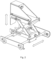
- Fig. 2 shows a newly developed truck system, with wheels that engage with rails of a rail system mounted to or of a switchgear, and where a centre connection section can be moved laterally and vertically.
- the connection section in the middle can slide sideways on bars extending between plates that hold two sets of wheels on either side that engage with the rails of the rail system.
- the wheels can sit on top of the rails, or slide down a centre conduit open on the inside of the rails, such that once engaged with the rails the wheels cannot be lifted off the rails, but only slid out of the end.
- the connection section also has a scissor like extension functionality enabling leg sections joined at midpoints to change the angle between them by using a threaded screw to raise and lower the part of the connection section that will connect to a current transformer.
- Fig. 3 shows several views of a truck system, with wheels that engage with rails of a rail system mounted to or of a switchgear, and where a centre connection section can be moved laterally and vertically. This shows different horizontal positions of the connection section and different vertical positions of the connection section.
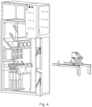
- Fig. 4 shows a compartment of a switchgear on the left within which are three current transformers and on the right a switchgear current transformer replacement system having a rail system and a truck system, where the truck system is shown already engaged with the rail system.
- the truck system is shown already engaged with the rail system, but it can disengage from the rail system if required.
- the rail system is shown separate to the switchgear compartment, but existing rails of a switchgear can be utilized in certain situation.
- Fig. 5 shows the compartment of the switchgear as shown in Fig. 4 , where the rail system of the switchgear current transformer replacement system has been mounted within the compartment, and where the truck system is shown on the right.
- Fig. 6 shows the compartment of the switchgear as shown in Figs. 4-5 , where the truck system has engaged with the rail system mounted within the switchgear and the truck system has engaged with the rail system with its wheels placed on the rails. The truck system has been moved forwards by rolling along its wheels to be adjacent to a current transformer. The connection section of the truck system is then mechanically connected to the current transformer.
- Fig. 7 shows the compartment of the switchgear as shown in Figs. 4-6 , where a connection section of the truck system has connected to the current transformer and the truck system along with the current transformer has been moved backwards by rolling along its wheels to move the current transformer away from its operational location.
- Fig. 8 shows the compartment of the switchgear as shown in Figs. 4-7 , where the truck system along with the current transformer has been moved to the end of the rails of the rail system and dis-engaged from the rails in order to removed the current transformer from the switchgear compartment.
- the truck system with the current transformer has been placed on a table or box next to the compartment, and if the height of the box is the same height as the rails of the rail system the truck system can be easily rolled onto to the table or box.
- the current transformer can then be disconnected from the connection section of the truck system.
- a replacement current transformer connected to the connection section The truck system can then be engaged again with the rail system, and rolled forward to place the replacement current transformer in its operational location.
- the replacement current transformer can then be disconnected from the connection section.
- the truck section with can then be rolled backwards and disengaged from the rail system, and the rail system can be dismounted from the compartment.
Landscapes
- Engineering & Computer Science (AREA)
- Power Engineering (AREA)
- Manufacturing & Machinery (AREA)
- Trip Switchboards (AREA)
- Electric Propulsion And Braking For Vehicles (AREA)
- Gas-Insulated Switchgears (AREA)
Abstract
- a truck system;
wherein the truck system comprises a connection section;
wherein the truck system is configured to engage with and move along one or more rails of a rail system of a compartment of a switchgear;
wherein the connection section of the truck system is configured to connect to a current transformer;
wherein the truck system when engaged with the one or more rails of the rail system is configured to move along the one or more rails of the rail system to a position adjacent to the current transformer at its operational location within the compartment of the switchgear;
wherein when the truck system is engaged with the one or more rails of the rail system, when the truck system is adjacent to the current transformer at its operational location within the compartment of the switchgear the connection section of the truck system is configured to connect to the current transformer; and
wherein when the truck system is connected to the current transformer, when engaged with the one or more rails of the rail system and when the connection section is connected to the current transformer the truck system is configured to move along the one or more rails of the rail system with the current transformer to move the current transformer away from its operational location within the compartment of the switchgear.
Description
- The present invention relates to switchgear current transformer replacement systems and switchgear current transformer replacement methods.
- Current transformers in switchgear (or panels) are sometimes required to be replaced, because the current transformer could be faulty or the voltage rating of the switchgear could be changing, or the current transformer has come to the end of its lifetime.
- However, it is a difficult job to replace these current transformers, because they tend to be heavy, bulky and be in locations of a switchgear compartment that are difficult to assess.
- In many cases, replacement of current transformers takes a long time, and requires access to both the front and rear of the compartment of the switchgear and can require removal of front and rear walls of the compartment of the switchgear.
- There is a need to address these issues.
- Therefore, it would be advantageous to have an improved technique for replacing switchgear current transformers.
- The object of the present invention is solved with the subject matter of the independent claims, wherein further embodiments are incorporated in the dependent claims.
- In a first aspect, there is provided a switchgear current transformer replacement system comprising:
- a truck system.
- Thus, a truck system can be placed on and moved along existing rails in a compartment of a switchgear in a first direction in order to move up to a current transformer in the compartment. The truck system can then connect to the current transformer in order to extract the current transformer by moving the truck system in a second direction opposite to the first direction. In this way, a simple means is provided to help replace current transformers in a switchgear compartment that only requires one side of the compartment to be opened, reducing the time to replace current transformers, reducing the chance of injury, and saving costs and work and downtime considerably.
- In an example, the one or more rails of the rail system comprises at least two rails parallel to each other.
- In this manner, a stable platform for the truck system is provided.
- In an example, the truck system comprises one or more wheels that are configured to roll along the one or rails of the rail system.
- In an example, the truck system comprises two or more wheels, wherein at least one wheel is configured to roll along a first rail of the at least two rails and at least one wheel is configured to roll along a second rail of the at least two rails.
- In an example, at least two wheels of the truck system are configured to roll along the first rail of the at least two rails and at least two wheels of the truck system are configured to roll along the second rail of the at least two rails.
- Thus, the truck system can be easily placed on or engaged with the rail(s) of the rail system, and easily moved forward and backwards along the rail(s) to extract a current transformer, and then replace the current transformer with a new unit.
- In an example, the truck system when engaged with the one or more rails of the rail system is configured to move the connection section in at least one direction perpendicular to the one or more rails of the rail system.
- In an example, the truck system is configured to move the connection section of the truck system in a direction parallel to a direction extending from a first rail of the one or more rails to a second rail of the one or more rails, and wherein the truck system is configured to move the connection section of the truck system in a direction perpendicular to the direction extending from the first rail of the one or more rails to the second rail of the one or more rails.
- In this manner, the truck system can be accurately aligned with a current transformer in order to remove it from the compartment, and indeed the truck system can also be aligned with each current transformer for each phase of a three phase system enabling the current transformer for any of the phases to be replaced.
- In a second aspect, there is provided a switchgear current transformer replacement system comprising:
- a rail system; and
- a truck system.
- In this manner, a special set of rails can be mounted to a compartment of a switchgear, for example at locations of circuit breaker rails.
- Then a truck system can moved along the rails in a first direction in order to move up to a current transformer in the compartment. The truck system can then connect to the current transformer in order to extract the current transformer by moving the truck system in a second direction opposite to the first direction. In this way, a simple means is provided to help replace current transformers in a switchgear compartment that only requires one side of the compartment to be opened, reducing the time to replace current transformers, reducing the chance of injury, and saving costs and work and downtime considerably. The rails can then be removed from the compartment.
- In an example, the truck system is configured to engage with the one or more rails of the rail system of the compartment of the switchgear prior to moving the truck system along the one or more rails of the rail system.
- Thus, the rail system that is mounted to the compartment of the switchgear can have a truck system integrated with it, or the truck system can be separate to the rail system. In this manner, the new system can be utilized with existing switchgear and their compartments in that the rail(s) are mounted to the existing compartments. Or existing rails of switchgear can be utilized, such as circuit breaker tracks or rails in certain situations, or new switchgear compartments can be manufactured with rail(s) of the new system already present with the compartment that will house current transformers.
- In an example, the one or more rails of the rail system comprises at least two rails parallel to each other.
- In an example, the truck system comprises one or more wheels that are configured to roll along the one or rails of the rail system.
- In an example, the truck system comprises two or more wheels, wherein at least one wheel is configured to roll along a first rail of the at least two rails and at least one wheel is configured to roll along a second rail of the at least two rails.
- In an example, at least two wheels of the truck system are configured to roll along the first rail of the at least two rails and at least two wheels of the truck system are configured to roll along the second rail of the at least two rails.
- In an example, the truck system when engaged with the one or more rails of the rail system is configured to move the connection section in at least one direction perpendicular to the one or more rails of the rail system.
- In an example, the truck system is configured to move the connection section of the truck system in a direction parallel to a direction extending from a first rail of the one or more rails to a second rail of the one or more rails, and the truck system is configured to move the connection section of the truck system in a direction perpendicular to the direction extending from the first rail of the one or more rails to the second rail of the one or more rails.
- In a third aspect, there is provided a switchgear current transformer replacement method comprising:
- engaging a truck system with one or more rails of a rail system of a compartment of a switchgear;
- moving the truck system along the one or more rails of a rail system of the compartment of the switchgear to a position adjacent to a current transformer of the switchgear at its operational location within the compartment of the switchgear;
- connecting a connection section of the truck system to the current transformer; and
- moving the truck system along the one or more rails of the rail system with the current transformer to move the current transformer away from its operational location within the compartment of the switchgear.
- In an example, the one or more rails of the rail system comprises at least two rails parallel to each other.
- In an example, the truck system comprises one or more wheels that are configured to roll along the one or rails of the rail system.
- In an example, the truck system comprises two or more wheels, wherein at least one wheel is configured to roll along a first rail of the at least two rails and at least one wheel is configured to roll along a second rail of the at least two rails.
- In an example, at least two wheels of the truck system are configured to roll along the first rail of the at least two rails and at least two wheels of the truck system are configured to roll along the second rail of the at least two rails.
- In an example, the method comprises moving the connection section in at least one direction perpendicular to the one or more rails of the rail system.
- In an example, the method comprises moving the connection section of the truck system in a direction parallel to a direction extending from a first rail of the one or more rails to a second rail of the one or more rails.
- In an example, the method comprises moving the connection section of the truck system in a direction perpendicular to the direction extending from the first rail of the one or more rails to the second rail of the one or more rails.
- In a fourth aspect, there is provided a switchgear current transformer replacement method comprising:
- mounting a rail system to a compartment of a switchgear, wherein the rail system comprises one or more rails;
- moving a truck system along the one or more rails of the rail system to a position adjacent to a current transformer at its operational location within the compartment of the switchgear;
- connecting a connection section of the truck system to the current transformer; and
- moving the truck system along the one or more rails of the rail system with the current transformer to move the current transformer away from its operational location within the compartment of the switchgear.
- In an example, the method comprises engaging the truck system with the one or more rails of the rail system of the compartment of the switchgear prior to moving the truck system along the one or more rails of the rail system.
- In an example, the one or more rails of the rail system comprises at least two rails parallel to each other.
- In an example, the truck system comprises one or more wheels that are configured to roll along the one or rails of the rail system.
- In an example, the truck system comprises two or more wheels, wherein at least one wheel is configured to roll along a first rail of the at least two rails and at least one wheel is configured to roll along a second rail of the at least two rails.
- In an example, at least two wheels of the truck system are configured to roll along the first rail of the at least two rails and at least two wheels of the truck system are configured to roll along the second rail of the at least two rails.
- In an example, the method comprises moving the connection section in at least one direction perpendicular to the one or more rails of the rail system.
- In an example, the method comprises moving the connection section of the truck system in a direction parallel to a direction extending from a first rail of the one or more rails to a second rail of the one or more rails.
- In an example, the method comprises moving the connection section of the truck system in a direction perpendicular to the direction extending from the first rail of the one or more rails to the second rail of the one or more rails.
- The above aspects and examples will become apparent from and be elucidated with reference to the embodiments described hereinafter.
- Exemplary embodiments will be described in the following with reference to the following drawings:
-
Fig. 1 shows a sideview of a switchgear compartment with an arrow showing how a current transformer is to be removed from the compartment, where the current transformer is located at the rear of the arrow; -
Fig. 2 shows a truck system, with wheels that engage with rails of a rail system mounted to or of a switchgear, and where a centre connection section can be moved laterally and vertically; -
Fig. 3 shows several views of a truck system, with wheels that engage with rails of a rail system mounted to or of a switchgear, and where a centre connection section can be moved laterally and vertically; and -
Fig. 4 shows a compartment of a switchgear on the left within which are three current transformers and on the right a switchgear current transformer replacement system having a rail system and a truck system, where the truck system is shown already engaged with the rail system; -
Fig. 5 shows the compartment of the switchgear as shown inFig. 4 , where the rail system of the switchgear current transformer replacement system has been mounted within the compartment, and where the truck system is shown on the right; -
Fig. 6 shows the compartment of the switchgear as shown inFigs. 4-5 , where truck system has engaged with the rail system mounted within the switchgear and the truck system has engaged with the rail system with its wheels placed on the rails, and the truck system has been moved forwards by rolling along its wheels to be adjacent to a current transformer; -
Fig. 7 shows the compartment of the switchgear as shown inFigs. 4-6 , where a connection section of the truck system has connected to the current transformer and the truck system along with the current transformer has been moved backwards by rolling along its wheels to move the current transformer away from its operational location; and -
Fig. 8 shows the compartment of the switchgear as shown inFigs. 4-7 , where the truck system along with the current transformer has been moved to the end of the rails of the rail system and dis-engaged from the rails in order to removed the current transformer from the switchgear compartment. -
Fig. 1 shows a sideview of a switchgear compartment with an arrow showing how a current transformer is to be removed from the compartment, where the current transformer is located at the rear of the arrow. -
Figs. 2-8 relate to the new switchgear current transformer replacement systems and the new switchgear current transformer replacement methods. - In an example a switchgear current transformer replacement system comprises a truck system. The truck system comprises a connection section. The truck system is configured to engage with and move along one or more rails of a rail system of a compartment of a switchgear. The connection section of the truck system is configured to connect to a current transformer. The truck system when engaged with the one or more rails of the rail system is configured to move along the one or more rails of the rail system to a position adjacent to the current transformer at its operational location within the compartment of the switchgear. When the truck system is engaged with the one or more rails of the rail system, and when the truck system is adjacent to the current transformer at its operational location within the compartment of the switchgear the connection section of the truck system is configured to connect to the current transformer. When the truck system is connected to the current transformer, and when the truck system is engaged with the one or more rails of the rail system and when the connection section is connected to the current transformer the truck system is configured to move along the one or more rails of the rail system with the current transformer to move the current transformer away from its operational location within the compartment of the switchgear.
- Thus, a truck system can be placed on and moved along existing rails in a compartment of a switchgear in a first direction in order to move up to a current transformer in the compartment. The truck system can then connect to the current transformer in order to extract the current transformer by moving the truck system in a second direction opposite to the first direction. In this way, a simple means is provided to help replace current transformers in a switchgear compartment that only requires one side of the compartment to be opened.
- In an example, the one or more rails of the rail system comprises at least two rails parallel to each other.
- In this manner, a stable platform for the truck system is provided.
- In an example, the truck system comprises one or more wheels that are configured to roll along the one or rails of the rail system.
- In an example, the truck system comprises two or more wheels, wherein at least one wheel is configured to roll along a first rail of the at least two rails and at least one wheel is configured to roll along a second rail of the at least two rails.
- In an example, at least two wheels of the truck system are configured to roll along the first rail of the at least two rails and at least two wheels of the truck system are configured to roll along the second rail of the at least two rails.
- Thus, the truck system can be easily placed on or engaged with the rail(s) of the rail system, and easily moved forward and backwards along the rail(s) to extract a current transformer, and then replace the current transformer with a new unit.
- In an example, the truck system when engaged with the one or more rails of the rail system is configured to move the connection section in at least one direction perpendicular to the one or more rails of the rail system.
- In an example, the truck system is configured to move the connection section of the truck system in a direction parallel to a direction extending from a first rail of the one or more rails to a second rail of the one or more rails, and wherein the truck system is configured to move the connection section of the truck system in a direction perpendicular to the direction extending from the first rail of the one or more rails to the second rail of the one or more rails.
- In this manner, the truck system can be accurately aligned with a current transformer in order to remove it from the compartment, and indeed the truck system can also be aligned with each current transformer for each phase of a three phase system enabling the current transformer for any of the phases to be replaced.
- In an example a switchgear current transformer replacement system comprises a rail system, and a truck system. The rail system is configured to be mounted to a compartment of a switchgear. The rail system comprises one or more rails. The truck system comprises a connection section. The truck system is configured to move along the one or more rails of the rail system. The connection section of the truck system is configured to connect to a current transformer. When the rail system is mounted to the compartment of the switchgear, the truck system is configured to move along the one or more rails of the rail system to a position adjacent to the current transformer at its operational location within the compartment of the switchgear. When the truck system is adjacent to the current transformer at its operational location within the compartment of the switchgear the connection section of the truck system is configured to connect to the current transformer. When the truck system is connected to the current transformer, and when the connection section is connected to the current transformer, the truck system is configured to move along the one or more rails of the rail system with the current transformer to move the current transformer away from its operational location within the compartment of the switchgear.
- In this manner, a special set of rails can be mounted to a compartment of a switchgear, for example at locations of circuit breaker rails or tracks.
- Then a truck system can moved along the rails in a first direction in order to move up to a current transformer in the compartment. The truck system can then connect to the current transformer in order to extract the current transformer by moving the truck system in a second direction opposite to the first direction. In this way, a simple means is provided to help replace current transformers in a switchgear compartment that only requires one side of the compartment to be opened, reducing the time to replace current transformers, and saving costs and work and downtime considerably. The rails can then be removed from the compartment.
- In an example, the truck system is configured to engage with the one or more rails of the rail system of the compartment of the switchgear prior to moving the truck system along the one or more rails of the rail system.
- Thus, the rail system that is mounted to the compartment of the switchgear can have a truck system integrated with it, or the truck system can be separate to the rail system. In this manner, the new system can be utilized with existing switchgear and their compartments in that the rail(s) are mounted to the existing compartments. Or existing rails of switchgear can be utilized, such as circuit breaker rails in certain situations, or new switchgear compartments can be manufactured with rail(s) of the new system already present with the compartment that will house current transformers.
- In an example, the one or more rails of the rail system comprises at least two rails parallel to each other.
- In an example, the truck system comprises one or more wheels that are configured to roll along the one or rails of the rail system.
- In an example, the truck system comprises two or more wheels, wherein at least one wheel is configured to roll along a first rail of the at least two rails and at least one wheel is configured to roll along a second rail of the at least two rails.
- In an example, at least two wheels of the truck system are configured to roll along the first rail of the at least two rails and at least two wheels of the truck system are configured to roll along the second rail of the at least two rails.
- In an example, the truck system when engaged with the one or more rails of the rail system is configured to move the connection section in at least one direction perpendicular to the one or more rails of the rail system.
- In an example, the truck system is configured to move the connection section of the truck system in a direction parallel to a direction extending from a first rail of the one or more rails to a second rail of the one or more rails, and the truck system is configured to move the connection section of the truck system in a direction perpendicular to the direction extending from the first rail of the one or more rails to the second rail of the one or more rails.
- In an example a switchgear current transformer replacement method comprises
- engaging a truck system with one or more rails of a rail system of a compartment of a switchgear;
- moving the truck system along the one or more rails of a rail system of the compartment of the switchgear to a position adjacent to a current transformer of the switchgear at its operational location within the compartment of the switchgear;
- connecting a connection section of the truck system to the current transformer; and
- moving the truck system along the one or more rails of the rail system with the current transformer to move the current transformer away from its operational location within the compartment of the switchgear.
- In an example, the one or more rails of the rail system comprises at least two rails parallel to each other.
- In an example, the truck system comprises one or more wheels that are configured to roll along the one or rails of the rail system.
- In an example, the truck system comprises two or more wheels, wherein at least one wheel is configured to roll along a first rail of the at least two rails and at least one wheel is configured to roll along a second rail of the at least two rails.
- In an example, at least two wheels of the truck system are configured to roll along the first rail of the at least two rails and at least two wheels of the truck system are configured to roll along the second rail of the at least two rails.
- In an example, the method comprises moving the connection section in at least one direction perpendicular to the one or more rails of the rail system.
- In an example, the method comprises moving the connection section of the truck system in a direction parallel to a direction extending from a first rail of the one or more rails to a second rail of the one or more rails.
- In an example, the method comprises moving the connection section of the truck system in a direction perpendicular to the direction extending from the first rail of the one or more rails to the second rail of the one or more rails.
- In an example a switchgear current transformer replacement method comprises:
- mounting a rail system to a compartment of a switchgear, wherein the rail system comprises one or more rails;
- moving a truck system along the one or more rails of the rail system to a position adjacent to a current transformer at its operational location within the compartment of the switchgear;
- connecting a connection section of the truck system to the current transformer; and
- moving the truck system along the one or more rails of the rail system with the current transformer to move the current transformer away from its operational location within the compartment of the switchgear.
- In an example, the method comprises engaging the truck system with the one or more rails of the rail system of the compartment of the switchgear prior to moving the truck system along the one or more rails of the rail system.
- In an example, the one or more rails of the rail system comprises at least two rails parallel to each other.
- In an example, the truck system comprises one or more wheels that are configured to roll along the one or rails of the rail system.
- In an example, the truck system comprises two or more wheels, wherein at least one wheel is configured to roll along a first rail of the at least two rails and at least one wheel is configured to roll along a second rail of the at least two rails.
- In an example, at least two wheels of the truck system are configured to roll along the first rail of the at least two rails and at least two wheels of the truck system are configured to roll along the second rail of the at least two rails.
- In an example, the method comprises moving the connection section in at least one direction perpendicular to the one or more rails of the rail system.
- In an example, the method comprises moving the connection section of the truck system in a direction parallel to a direction extending from a first rail of the one or more rails to a second rail of the one or more rails.
- In an example, the method comprises moving the connection section of the truck system in a direction perpendicular to the direction extending from the first rail of the one or more rails to the second rail of the one or more rails.
- The new switchgear current transformer replacement systems and the new switchgear current transformer replacement methods and now described in further specific detail, where reference is again made to
Figs. 1-8 . -
Fig. 1 shows a sideview of a switchgear compartment with an arrow showing how a current transformer is to be removed from the compartment, where the current transformer is located at the rear of the arrow. The current transformer is heavy and its location means that until development of the new switchgear current transformer replacement systems and the new switchgear current transformer replacement methods, the front walls and rears of the compartment has to be opened to allow access to personnel to remove a current transformer. -
Fig. 2 shows a newly developed truck system, with wheels that engage with rails of a rail system mounted to or of a switchgear, and where a centre connection section can be moved laterally and vertically. The connection section in the middle can slide sideways on bars extending between plates that hold two sets of wheels on either side that engage with the rails of the rail system. The wheels can sit on top of the rails, or slide down a centre conduit open on the inside of the rails, such that once engaged with the rails the wheels cannot be lifted off the rails, but only slid out of the end. The connection section also has a scissor like extension functionality enabling leg sections joined at midpoints to change the angle between them by using a threaded screw to raise and lower the part of the connection section that will connect to a current transformer. -
Fig. 3 shows several views of a truck system, with wheels that engage with rails of a rail system mounted to or of a switchgear, and where a centre connection section can be moved laterally and vertically. This shows different horizontal positions of the connection section and different vertical positions of the connection section. -
Fig. 4 shows a compartment of a switchgear on the left within which are three current transformers and on the right a switchgear current transformer replacement system having a rail system and a truck system, where the truck system is shown already engaged with the rail system. This shows a representation of how the new switchgear current transformer replacement system will interact with the switchgear compartment. The truck system is shown already engaged with the rail system, but it can disengage from the rail system if required. Also, the rail system is shown separate to the switchgear compartment, but existing rails of a switchgear can be utilized in certain situation. -
Fig. 5 shows the compartment of the switchgear as shown inFig. 4 , where the rail system of the switchgear current transformer replacement system has been mounted within the compartment, and where the truck system is shown on the right. -
Fig. 6 shows the compartment of the switchgear as shown inFigs. 4-5 , where the truck system has engaged with the rail system mounted within the switchgear and the truck system has engaged with the rail system with its wheels placed on the rails. The truck system has been moved forwards by rolling along its wheels to be adjacent to a current transformer. The connection section of the truck system is then mechanically connected to the current transformer. -
Fig. 7 shows the compartment of the switchgear as shown inFigs. 4-6 , where a connection section of the truck system has connected to the current transformer and the truck system along with the current transformer has been moved backwards by rolling along its wheels to move the current transformer away from its operational location. -
Fig. 8 shows the compartment of the switchgear as shown inFigs. 4-7 , where the truck system along with the current transformer has been moved to the end of the rails of the rail system and dis-engaged from the rails in order to removed the current transformer from the switchgear compartment. The truck system with the current transformer has been placed on a table or box next to the compartment, and if the height of the box is the same height as the rails of the rail system the truck system can be easily rolled onto to the table or box. The current transformer can then be disconnected from the connection section of the truck system. A replacement current transformer connected to the connection section. The truck system can then be engaged again with the rail system, and rolled forward to place the replacement current transformer in its operational location. The replacement current transformer can then be disconnected from the connection section. The truck section with can then be rolled backwards and disengaged from the rail system, and the rail system can be dismounted from the compartment.
Claims (15)
- A switchgear current transformer replacement system comprising:- a truck system;wherein the truck system comprises a connection section;wherein the truck system is configured to engage with and move along one or more rails of a rail system of a compartment of a switchgear;wherein the connection section of the truck system is configured to connect to a current transformer;wherein the truck system when engaged with the one or more rails of the rail system is configured to move along the one or more rails of the rail system to a position adjacent to the current transformer at its operational location within the compartment of the switchgear;wherein when the truck system is engaged with the one or more rails of the rail system, when the truck system is adjacent to the current transformer at its operational location within the compartment of the switchgear the connection section of the truck system is configured to connect to the current transformer; andwherein when the truck system is connected to the current transformer, when engaged with the one or more rails of the rail system and when the connection section is connected to the current transformer the truck system is configured to move along the one or more rails of the rail system with the current transformer to move the current transformer away from its operational location within the compartment of the switchgear.
- System according to claim 1, wherein the one or more rails of the rail system comprises at least two rails parallel to each other.
- System according to any of claim 1-2, wherein the truck system comprises one or more wheels that are configured to roll along the one or rails of the rail system.
- System according to claim 3 when dependent upon claim 2, wherein the truck system comprises two or more wheels, wherein at least one wheel is configured to roll along a first rail of the at least two rails and at least one wheel is configured to roll along a second rail of the at least two rails.
- System according to claim 4, wherein at least two wheels of the truck system are configured to roll along the first rail of the at least two rails and at least two wheels of the truck system are configured to roll along the second rail of the at least two rails.
- System according to any of claims 1-5, wherein the truck system when engaged with the one or more rails of the rail system is configured to move the connection section in at least one direction perpendicular to the one or more rails of the rail system.
- System according to claim 6 when dependent upon claim 2 or any of claims 3-5 when dependent upon claim 2, wherein the truck system is configured to move the connection section of the truck system in a direction parallel to a direction extending from a first rail of the one or more rails to a second rail of the one or more rails, and wherein the truck system is configured to move the connection section of the truck system in a direction perpendicular to the direction extending from the first rail of the one or more rails to the second rail of the one or more rails.
- A switchgear current transformer replacement system comprising:- a rail system; and- a truck system;wherein the rail system is configured to be mounted to a compartment of a switchgear;wherein the rail system comprises one or more rails;wherein the truck system comprises a connection section;wherein the truck system is configured to move along the one or more rails of the rail system;wherein the connection section of the truck system is configured to connect to a current transformer;wherein when the rail system is mounted to the compartment of the switchgear, the truck system is configured to move along the one or more rails of the rail system to a position adjacent to the current transformer at its operational location within the compartment of the switchgear;wherein when the truck system is adjacent to the current transformer at its operational location within the compartment of the switchgear the connection section of the truck system is configured to connect to the current transformer; andwherein when the truck system is connected to the current transformer, when the connection section is connected to the current transformer the truck system is configured to move along the one or more rails of the rail system with the current transformer to move the current transformer away from its operational location within the compartment of the switchgear.
- System according to claim 8, wherein the one or more rails of the rail system comprises at least two rails parallel to each other.
- System according to any of claim 8-9, wherein the truck system comprises one or more wheels that are configured to roll along the one or rails of the rail system.
- System according to claim 10 when dependent upon claim 9, wherein the truck system comprises two or more wheels, wherein at least one wheel is configured to roll along a first rail of the at least two rails and at least one wheel is configured to roll along a second rail of the at least two rails.
- System according to claim 11, wherein at least two wheels of the truck system are configured to roll along the first rail of the at least two rails and at least two wheels of the truck system are configured to roll along the second rail of the at least two rails.
- System according to any of claims 8-12, wherein the truck system when engaged with the one or more rails of the rail system is configured to move the connection section in at least one direction perpendicular to the one or more rails of the rail system.
- A switchgear current transformer replacement method comprising:engaging a truck system with one or more rails of a rail system of a compartment of a switchgear;moving the truck system along the one or more rails of a rail system of the compartment of the switchgear to a position adjacent to a current transformer of the switchgear at its operational location within the compartment of the switchgear;connecting a connection section of the truck system to the current transformer; andmoving the truck system along the one or more rails of the rail system with the current transformer to move the current transformer away from its operational location within the compartment of the switchgear.
- A switchgear current transformer replacement method comprising:mounting a rail system to a compartment of a switchgear, wherein the rail system comprises one or more rails;moving a truck system along the one or more rails of the rail system to a position adjacent to a current transformer at its operational location within the compartment of the switchgear;connecting a connection section of the truck system to the current transformer; andmoving the truck system along the one or more rails of the rail system with the current transformer to move the current transformer away from its operational location within the compartment of the switchgear.
Priority Applications (3)
| Application Number | Priority Date | Filing Date | Title |
|---|---|---|---|
| EP22213716.8A EP4387018A1 (en) | 2022-12-15 | 2022-12-15 | Switchgear current transformer replacement system |
| US18/537,059 US12614894B2 (en) | 2022-12-15 | 2023-12-12 | Switchgear current transformer replacement system |
| CN202311722201.8A CN118213895A (en) | 2022-12-15 | 2023-12-14 | Switchgear Current Transformer Replacement System |
Applications Claiming Priority (1)
| Application Number | Priority Date | Filing Date | Title |
|---|---|---|---|
| EP22213716.8A EP4387018A1 (en) | 2022-12-15 | 2022-12-15 | Switchgear current transformer replacement system |
Publications (1)
| Publication Number | Publication Date |
|---|---|
| EP4387018A1 true EP4387018A1 (en) | 2024-06-19 |
Family
ID=84537785
Family Applications (1)
| Application Number | Title | Priority Date | Filing Date |
|---|---|---|---|
| EP22213716.8A Pending EP4387018A1 (en) | 2022-12-15 | 2022-12-15 | Switchgear current transformer replacement system |
Country Status (3)
| Country | Link |
|---|---|
| US (1) | US12614894B2 (en) |
| EP (1) | EP4387018A1 (en) |
| CN (1) | CN118213895A (en) |
Citations (2)
| Publication number | Priority date | Publication date | Assignee | Title |
|---|---|---|---|---|
| CN201234073Y (en) * | 2008-07-12 | 2009-05-06 | 汕头正超电气集团有限公司 | Assembly cart apparatus for current mutual inductor |
| CN216289511U (en) * | 2021-10-27 | 2022-04-12 | 比亚迪股份有限公司 | Installation apparatus and installation system for current transformer and centrally installed switchgear |
Family Cites Families (10)
| Publication number | Priority date | Publication date | Assignee | Title |
|---|---|---|---|---|
| US3034658A (en) * | 1955-01-14 | 1962-05-15 | Mccabe Powers Body Company | Portable derricks |
| US3467217A (en) * | 1967-04-26 | 1969-09-16 | Mccabe Powers Body Co | Aerial platform unit |
| US3973754A (en) * | 1975-01-30 | 1976-08-10 | Sherman & Reilly, Inc. | Transformer caddie |
| US4042941A (en) * | 1975-12-29 | 1977-08-16 | Campbell Ernest E | Vehicle for transporting and elevating articles in restricted areas |
| JP5625971B2 (en) * | 2011-02-08 | 2014-11-19 | 住友電装株式会社 | Internal circuit structure for electric junction box and electric junction box using the same |
| US20130176046A1 (en) * | 2012-01-05 | 2013-07-11 | General Electric Company | Mobile transformer testing system |
| US20130174497A1 (en) * | 2012-01-05 | 2013-07-11 | General Electric Company | System and method for transformer repair |
| CA2840383A1 (en) * | 2014-01-21 | 2015-07-21 | Abb Inc. | Site replacement of internal saturable reactors of a rectifier power transformer |
| US10626632B2 (en) * | 2017-09-25 | 2020-04-21 | Sauber Manufacturing Company | Mobile utility pole |
| US20230187913A1 (en) * | 2021-12-10 | 2023-06-15 | Dte Electric Company | System for Temporarily Mounting Overhead Equipment on a Utility Pole Without Damaging the Pole and Assembly for Use Therein |
-
2022
- 2022-12-15 EP EP22213716.8A patent/EP4387018A1/en active Pending
-
2023
- 2023-12-12 US US18/537,059 patent/US12614894B2/en active Active
- 2023-12-14 CN CN202311722201.8A patent/CN118213895A/en active Pending
Patent Citations (2)
| Publication number | Priority date | Publication date | Assignee | Title |
|---|---|---|---|---|
| CN201234073Y (en) * | 2008-07-12 | 2009-05-06 | 汕头正超电气集团有限公司 | Assembly cart apparatus for current mutual inductor |
| CN216289511U (en) * | 2021-10-27 | 2022-04-12 | 比亚迪股份有限公司 | Installation apparatus and installation system for current transformer and centrally installed switchgear |
Also Published As
| Publication number | Publication date |
|---|---|
| CN118213895A (en) | 2024-06-18 |
| US20240204490A1 (en) | 2024-06-20 |
| US12614894B2 (en) | 2026-04-28 |
Similar Documents
| Publication | Publication Date | Title |
|---|---|---|
| US11646553B2 (en) | Method for installing a switching module in an electrical cabinet, corresponding installation kit and switching module | |
| CN202308881U (en) | Draw-out-type low-voltage switch equipment | |
| EP4387018A1 (en) | Switchgear current transformer replacement system | |
| EP3747116A1 (en) | Machines having power-electronic energy converters and leakage current compensation and system | |
| CN101599618B (en) | Electrical distribution device assembly | |
| US20220101751A1 (en) | Transformer training lab | |
| WO2022043279A2 (en) | Shuttle for a shelf system, and shelf system | |
| DE202020104954U1 (en) | Shuttle for a shelf system and shelf system | |
| US5280408A (en) | Power receiving and transforming apparatus | |
| KR100578451B1 (en) | Method and device for detecting location of fault point by electric quantity in electric railway system | |
| CN203674600U (en) | Upside-down mounting type chassis | |
| DE102009006951A1 (en) | Medium or high voltage switchgear | |
| CN112379305A (en) | Grounding detection circuit of traction converter and control method thereof | |
| CN203339550U (en) | Chassis vehicle and switch cabinet cooperating with same | |
| CN206412637U (en) | A kind of detachable deep beam | |
| CN220500754U (en) | A kind of SLVA cabinet transfer chassis vehicle with guardrail limit | |
| CN106130164B (en) | Motor train unit maintenance auxiliary power supply system | |
| CN101295858B (en) | Grooved tool for bypass jumper of low-voltage switchgear and its manufacturing process | |
| JP7106697B2 (en) | power board | |
| CN204481361U (en) | A kind of High-low voltage switch cabinet easy to loading and unloading | |
| CN218386394U (en) | Handcart type circuit breaker | |
| CN211017863U (en) | Draw-out type capacitor cabinet | |
| CN110091899B (en) | Transfer car (buggy) is put to pipe | |
| JP2020014296A (en) | Commutation type DC circuit breaker panel | |
| CN121133513A (en) | Method for detecting locomotive and rolling stock occupying single-pole DC track circuit of double-intersection turnout |
Legal Events
| Date | Code | Title | Description |
|---|---|---|---|
| PUAI | Public reference made under article 153(3) epc to a published international application that has entered the european phase |
Free format text: ORIGINAL CODE: 0009012 |
|
| STAA | Information on the status of an ep patent application or granted ep patent |
Free format text: STATUS: THE APPLICATION HAS BEEN PUBLISHED |
|
| AK | Designated contracting states |
Kind code of ref document: A1 Designated state(s): AL AT BE BG CH CY CZ DE DK EE ES FI FR GB GR HR HU IE IS IT LI LT LU LV MC ME MK MT NL NO PL PT RO RS SE SI SK SM TR |
|
| STAA | Information on the status of an ep patent application or granted ep patent |
Free format text: STATUS: REQUEST FOR EXAMINATION WAS MADE |
|
| 17P | Request for examination filed |
Effective date: 20241121 |
|
| RBV | Designated contracting states (corrected) |
Designated state(s): AL AT BE BG CH CY CZ DE DK EE ES FI FR GB GR HR HU IE IS IT LI LT LU LV MC ME MK MT NL NO PL PT RO RS SE SI SK SM TR |