EP4387009A1 - Structural arrangement in an electrical connection applied to a vehicle lamp - Google Patents
Structural arrangement in an electrical connection applied to a vehicle lamp Download PDFInfo
- Publication number
- EP4387009A1 EP4387009A1 EP23858474.2A EP23858474A EP4387009A1 EP 4387009 A1 EP4387009 A1 EP 4387009A1 EP 23858474 A EP23858474 A EP 23858474A EP 4387009 A1 EP4387009 A1 EP 4387009A1
- Authority
- EP
- European Patent Office
- Prior art keywords
- connector
- electrical connection
- housing
- headlight
- constructive arrangement
- Prior art date
- Legal status (The legal status is an assumption and is not a legal conclusion. Google has not performed a legal analysis and makes no representation as to the accuracy of the status listed.)
- Pending
Links
Images






Classifications
-
- H—ELECTRICITY
- H01—ELECTRIC ELEMENTS
- H01R—ELECTRICALLY-CONDUCTIVE CONNECTIONS; STRUCTURAL ASSOCIATIONS OF A PLURALITY OF MUTUALLY-INSULATED ELECTRICAL CONNECTING ELEMENTS; COUPLING DEVICES; CURRENT COLLECTORS
- H01R12/00—Structural associations of a plurality of mutually-insulated electrical connecting elements, specially adapted for printed circuits, e.g. printed circuit boards [PCB], flat or ribbon cables, or like generally planar structures, e.g. terminal strips, terminal blocks; Coupling devices specially adapted for printed circuits, flat or ribbon cables, or like generally planar structures; Terminals specially adapted for contact with, or insertion into, printed circuits, flat or ribbon cables, or like generally planar structures
- H01R12/70—Coupling devices
- H01R12/71—Coupling devices for rigid printing circuits or like structures
- H01R12/72—Coupling devices for rigid printing circuits or like structures coupling with the edge of the rigid printed circuits or like structures
- H01R12/722—Coupling devices for rigid printing circuits or like structures coupling with the edge of the rigid printed circuits or like structures coupling devices mounted on the edge of the printed circuits
- H01R12/724—Coupling devices for rigid printing circuits or like structures coupling with the edge of the rigid printed circuits or like structures coupling devices mounted on the edge of the printed circuits containing contact members forming a right angle
-
- F—MECHANICAL ENGINEERING; LIGHTING; HEATING; WEAPONS; BLASTING
- F21—LIGHTING
- F21V—FUNCTIONAL FEATURES OR DETAILS OF LIGHTING DEVICES OR SYSTEMS THEREOF; STRUCTURAL COMBINATIONS OF LIGHTING DEVICES WITH OTHER ARTICLES, NOT OTHERWISE PROVIDED FOR
- F21V23/00—Arrangement of electric circuit elements in or on lighting devices
- F21V23/06—Arrangement of electric circuit elements in or on lighting devices the elements being coupling devices, e.g. connectors
-
- B—PERFORMING OPERATIONS; TRANSPORTING
- B60—VEHICLES IN GENERAL
- B60Q—ARRANGEMENT OF SIGNALLING OR LIGHTING DEVICES, THE MOUNTING OR SUPPORTING THEREOF OR CIRCUITS THEREFOR, FOR VEHICLES IN GENERAL
- B60Q1/00—Arrangement of optical signalling or lighting devices, the mounting or supporting thereof or circuits therefor
- B60Q1/0088—Details of electrical connections
-
- F—MECHANICAL ENGINEERING; LIGHTING; HEATING; WEAPONS; BLASTING
- F21—LIGHTING
- F21S—NON-PORTABLE LIGHTING DEVICES; SYSTEMS THEREOF; VEHICLE LIGHTING DEVICES SPECIALLY ADAPTED FOR VEHICLE EXTERIORS
- F21S45/00—Arrangements within vehicle lighting devices specially adapted for vehicle exteriors, for purposes other than emission or distribution of light
-
- H—ELECTRICITY
- H01—ELECTRIC ELEMENTS
- H01R—ELECTRICALLY-CONDUCTIVE CONNECTIONS; STRUCTURAL ASSOCIATIONS OF A PLURALITY OF MUTUALLY-INSULATED ELECTRICAL CONNECTING ELEMENTS; COUPLING DEVICES; CURRENT COLLECTORS
- H01R13/00—Details of coupling devices of the kinds covered by groups H01R12/70 or H01R24/00 - H01R33/00
- H01R13/46—Bases; Cases
- H01R13/52—Dustproof, splashproof, drip-proof, waterproof, or flameproof cases
- H01R13/5202—Sealing means between parts of housing or between housing part and a wall, e.g. sealing rings
-
- H—ELECTRICITY
- H01—ELECTRIC ELEMENTS
- H01R—ELECTRICALLY-CONDUCTIVE CONNECTIONS; STRUCTURAL ASSOCIATIONS OF A PLURALITY OF MUTUALLY-INSULATED ELECTRICAL CONNECTING ELEMENTS; COUPLING DEVICES; CURRENT COLLECTORS
- H01R13/00—Details of coupling devices of the kinds covered by groups H01R12/70 or H01R24/00 - H01R33/00
- H01R13/46—Bases; Cases
- H01R13/52—Dustproof, splashproof, drip-proof, waterproof, or flameproof cases
- H01R13/5216—Dustproof, splashproof, drip-proof, waterproof, or flameproof cases characterised by the sealing material, e.g. gels or resins
-
- H—ELECTRICITY
- H01—ELECTRIC ELEMENTS
- H01R—ELECTRICALLY-CONDUCTIVE CONNECTIONS; STRUCTURAL ASSOCIATIONS OF A PLURALITY OF MUTUALLY-INSULATED ELECTRICAL CONNECTING ELEMENTS; COUPLING DEVICES; CURRENT COLLECTORS
- H01R13/00—Details of coupling devices of the kinds covered by groups H01R12/70 or H01R24/00 - H01R33/00
- H01R13/62—Means for facilitating engagement or disengagement of coupling parts or for holding them in engagement
- H01R13/627—Snap or like fastening
-
- H—ELECTRICITY
- H01—ELECTRIC ELEMENTS
- H01R—ELECTRICALLY-CONDUCTIVE CONNECTIONS; STRUCTURAL ASSOCIATIONS OF A PLURALITY OF MUTUALLY-INSULATED ELECTRICAL CONNECTING ELEMENTS; COUPLING DEVICES; CURRENT COLLECTORS
- H01R13/00—Details of coupling devices of the kinds covered by groups H01R12/70 or H01R24/00 - H01R33/00
- H01R13/73—Means for mounting coupling parts to apparatus or structures, e.g. to a wall
- H01R13/74—Means for mounting coupling parts in openings of a panel
- H01R13/748—Means for mounting coupling parts in openings of a panel using one or more screws
-
- F—MECHANICAL ENGINEERING; LIGHTING; HEATING; WEAPONS; BLASTING
- F21—LIGHTING
- F21S—NON-PORTABLE LIGHTING DEVICES; SYSTEMS THEREOF; VEHICLE LIGHTING DEVICES SPECIALLY ADAPTED FOR VEHICLE EXTERIORS
- F21S41/00—Illuminating devices specially adapted for vehicle exteriors, e.g. headlamps
-
- H—ELECTRICITY
- H01—ELECTRIC ELEMENTS
- H01R—ELECTRICALLY-CONDUCTIVE CONNECTIONS; STRUCTURAL ASSOCIATIONS OF A PLURALITY OF MUTUALLY-INSULATED ELECTRICAL CONNECTING ELEMENTS; COUPLING DEVICES; CURRENT COLLECTORS
- H01R12/00—Structural associations of a plurality of mutually-insulated electrical connecting elements, specially adapted for printed circuits, e.g. printed circuit boards [PCB], flat or ribbon cables, or like generally planar structures, e.g. terminal strips, terminal blocks; Coupling devices specially adapted for printed circuits, flat or ribbon cables, or like generally planar structures; Terminals specially adapted for contact with, or insertion into, printed circuits, flat or ribbon cables, or like generally planar structures
- H01R12/50—Fixed connections
- H01R12/51—Fixed connections for rigid printed circuits or like structures
- H01R12/55—Fixed connections for rigid printed circuits or like structures characterised by the terminals
- H01R12/58—Fixed connections for rigid printed circuits or like structures characterised by the terminals terminals for insertion into holes
-
- H—ELECTRICITY
- H01—ELECTRIC ELEMENTS
- H01R—ELECTRICALLY-CONDUCTIVE CONNECTIONS; STRUCTURAL ASSOCIATIONS OF A PLURALITY OF MUTUALLY-INSULATED ELECTRICAL CONNECTING ELEMENTS; COUPLING DEVICES; CURRENT COLLECTORS
- H01R2201/00—Connectors or connections adapted for particular applications
- H01R2201/26—Connectors or connections adapted for particular applications for vehicles
Definitions
- the present utility model describes a constructive arrangement in electrical connection applied to a vehicle headlight. More specifically, it comprises an electrical connection system for headlights arranged in a parallel position to the electronic board, where this embodiment allows for existing connector in the vehicle (counterpart) to connect to the headlight quickly and practically, facilitating the installation and maintenance of the product.
- This new embodiment brings advantages in the application of the product due to improving the means of connection and installation, improving the space and visualization for allocating the connector, in addition to improving the removal of the electrical connector next to the headlight due to the lock being visible and easily accessible.
- the electrical connector applied in parallel, allows for its application and arrangement in different shapes, which vary depending on the model of the counterpart, in addition to having a different number of terminals, allowing for electrical connection of headlights with different amounts of functions.
- the present embodiment does not allow the headlights to have a reduced size, in terms of depth, generating several inconveniences in the means of placing and removing the electrical connector next to the headlight.
- headlights have mounting restrictions in depth so that the market solution for this inconvenience is to mount a different connector with cable exit at 90°, however these connectors are special, having little availability on the market and a high cost.
- the present inventor seeking to solve market inconveniences, has developed a new embodiment of a connector applied to a vehicle headlight that allows it to be arranged in parallel to the rear of the headlight, reducing the total height even when the connector is mounted. Furthermore, it allows the use of market standard connectors which are easy to replace.
- the object of the present utility model is an electrical connection system for headlights arranged in a parallel position to the electronic board, so that this embodiment allows the existing connector in the vehicle (counterpart) to connect to the headlight quickly and practical, facilitating the installation and maintenance of the product.
- This new embodiment brings advantages in the application of the product due to improving the means of connection and installation, improving the space and visualization for allocating the connector, in addition to improving the removal of the electrical connector next to the headlight due to the lock being visible and easily accessible.
- a characteristic of the utility model is a constructive arrangement in electrical connection applied to a vehicle headlight that provides a housing equipped with internal projections allowing the positioning of the electronic board and screw to fix the connector.
- a characteristic of the utility model is a constructive arrangement in electrical connection applied to a vehicle headlight that provides a housing having a posterior projection that allows the fixation and positioning of the connector.
- a characteristic of the utility model is a constructive arrangement in electrical connection applied to a vehicle headlight that provides for the fixing of the connector, positioning in parallel to the structure of the headlight housing.
- a characteristic of the utility model is a constructive arrangement in electrical connection applied to a vehicle headlight that provides a connector allowing it to be arranged in parallel to the rear of the headlight, reducing the total height even when the connector is mounted.
- a characteristic of the utility model is a constructive arrangement in electrical connection applied to a vehicle headlight that provides a connector allowing the use of market standard connectors which are easy to replace.
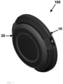
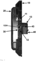
- the constructive arrangement in electrical connection applied to a vehicle headlight, object of the present utility model comprises a headlight (100) equipped with a housing (10), lens (20) and electronic board (30) with the LED lighting set.
- the housing (10) is internally equipped with projections (11) for positioning and fixing the electronic board (30) using a screw and in the medial portion it has a projection (12) equipped with an opening (121) that allows positioning and passage in the electrical connections between the board (30) and the connector.
- the projection (12) is equipped with holes (122) allowing the positioning of the screws (122A) for fixing next to the connector (40).
- a projection (13) positioned with the opening (121) that allows the positioning and fixing of the connector (40).
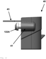
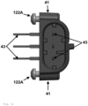
- the connector (40) is equipped with side projections with a hole (41) that allow the positioning of the screws (122A) to fix the connector to the housing (10).
- the connector (10) is equipped with a bas-relief (42) equipped with a set of grooves (421) that allows the positioning of the electrical terminals (43) that connect to the electronic board (30), said bas-relief (42) allowing the connection of the connector (40) to the projection (13) of the housing (10).
- the projection (13) is equipped with a groove (131) that allows positioning next to the bas-relief (42).
- the projection (13) is equipped with a groove (131) that allows positioning next to the bas-relief (42).
- This embodiment allows the connector (40) to be mounted on the housing (10) using screws (122A), with the electrical terminal (43) pre-assembled on the connector (40).
- the headlight connector (40) and housing (10) have a small channel, called a mechanical labyrinth, with a male and female fitting that deforms when the screws (122A) are tightened, so that they prevent the liquid resin from leaking through the connector (40) until it is cured (solidified).
- the connector (40) can have different shapes varying depending on the model of the counterpart and can also have a different number of terminals, allowing the electrical connection of headlights with different amounts of functions.
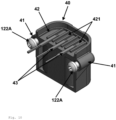
- Figures 16 and 17 show the 5- and 6-ways connector (40).
Landscapes
- Engineering & Computer Science (AREA)
- General Engineering & Computer Science (AREA)
- Chemical & Material Sciences (AREA)
- Dispersion Chemistry (AREA)
- Mechanical Engineering (AREA)
- Connector Housings Or Holding Contact Members (AREA)
- Details Of Connecting Devices For Male And Female Coupling (AREA)
- Arrangement Of Elements, Cooling, Sealing, Or The Like Of Lighting Devices (AREA)
- Non-Portable Lighting Devices Or Systems Thereof (AREA)
Abstract
Description
- The present utility model describes a constructive arrangement in electrical connection applied to a vehicle headlight. More specifically, it comprises an electrical connection system for headlights arranged in a parallel position to the electronic board, where this embodiment allows for existing connector in the vehicle (counterpart) to connect to the headlight quickly and practically, facilitating the installation and maintenance of the product. This new embodiment brings advantages in the application of the product due to improving the means of connection and installation, improving the space and visualization for allocating the connector, in addition to improving the removal of the electrical connector next to the headlight due to the lock being visible and easily accessible..
- The electrical connector, applied in parallel, allows for its application and arrangement in different shapes, which vary depending on the model of the counterpart, in addition to having a different number of terminals, allowing for electrical connection of headlights with different amounts of functions.
- Currently on the market, there are several models and types of headlights intended for vehicle and road implement applications, where they normally have an electrical connection made through a connector perpendicular to the electronic board and headlight housing.
- However, the present embodiment does not allow the headlights to have a reduced size, in terms of depth, generating several inconveniences in the means of placing and removing the electrical connector next to the headlight. Furthermore, headlights have mounting restrictions in depth so that the market solution for this inconvenience is to mount a different connector with cable exit at 90°, however these connectors are special, having little availability on the market and a high cost.
- Thus, the present inventor, seeking to solve market inconveniences, has developed a new embodiment of a connector applied to a vehicle headlight that allows it to be arranged in parallel to the rear of the headlight, reducing the total height even when the connector is mounted. Furthermore, it allows the use of market standard connectors which are easy to replace.
- In search performed on the prior art, we identified several models of headlights, where we can highlight the following documents:
-
US9461426 (Perterson. 2014 -
EP2345840 (Grote. 2010 ) describes an electrical connection device for a lamp housing that allows simple and direct alignment of circuit connector terminals with conductive power connection pads on a lamp circuit board within a lamp housing . -
BR8901844 (Aspoeck. 2009 - These documents described in the prior art describe vehicle side headlights equipped with embodiments applied to the electrical connection means, however these documents do not describe the same embodiment of a connector fixed and positioned in a parallel position to the electronic board, in order to facilitate the means of connection and reduce the space applied to installation.
- In this way, the object of the present utility model is an electrical connection system for headlights arranged in a parallel position to the electronic board, so that this embodiment allows the existing connector in the vehicle (counterpart) to connect to the headlight quickly and practical, facilitating the installation and maintenance of the product. This new embodiment brings advantages in the application of the product due to improving the means of connection and installation, improving the space and visualization for allocating the connector, in addition to improving the removal of the electrical connector next to the headlight due to the lock being visible and easily accessible.
- Such characteristics promote greater ease of installation and maintenance, when compared to prior art documents.
- A characteristic of the utility model is a constructive arrangement in electrical connection applied to a vehicle headlight that provides a housing equipped with internal projections allowing the positioning of the electronic board and screw to fix the connector.
- A characteristic of the utility model is a constructive arrangement in electrical connection applied to a vehicle headlight that provides a housing having a posterior projection that allows the fixation and positioning of the connector.
- A characteristic of the utility model is a constructive arrangement in electrical connection applied to a vehicle headlight that provides for the fixing of the connector, positioning in parallel to the structure of the headlight housing.
- A characteristic of the utility model is a constructive arrangement in electrical connection applied to a vehicle headlight that provides a connector allowing it to be arranged in parallel to the rear of the headlight, reducing the total height even when the connector is mounted.
- A characteristic of the utility model is a constructive arrangement in electrical connection applied to a vehicle headlight that provides a connector allowing the use of market standard connectors which are easy to replace.
-
-
Figure 1 shows the perspective view of the headlight with the parallel connector. -
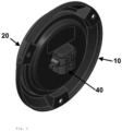
Figure 2 shows the rear perspective view of the headlight with the parallel connector. -
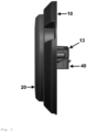
Figure 3 shows the side view of the headlight with the parallel connector. -
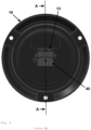
Figure 4 shows the rear view of the headlight with the parallel connector. -
Figure 5 shows the side sectional view of the headlight with the parallel connector. -
Figure 6 shows a perspective view of the headlight housing with the parallel connector. -
Figure 7 shows the rear perspective view of the headlight housing with the parallel connector. -
Figure 8 shows the rear exploded perspective view of the headlight housing with the parallel connector. -
Figure 9 shows the rear exploded bottom perspective view of the headlight housing with the parallel connector. -
Figure 10 shows the perspective view of the parallel connector. -
Figure 11 shows the front view of the connector. -
Figure 12 shows the side view of the connector. -
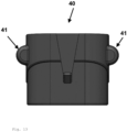
Figure 13 shows the rear view of the connector. -
Figure 14 shows the bottom perspective view of the parallel connector. -
Figure 15 shows the bottom view of the connector. -
Figure 16 shows the rear perspective view with the connector in transparency, demonstrating the 5-way connection. -
Figure 17 shows the rear perspective view with the connector in transparency, demonstrating the 7-way connection. - The constructive arrangement in electrical connection applied to a vehicle headlight, object of the present utility model, comprises a headlight (100) equipped with a housing (10), lens (20) and electronic board (30) with the LED lighting set.
- The housing (10) is internally equipped with projections (11) for positioning and fixing the electronic board (30) using a screw and in the medial portion it has a projection (12) equipped with an opening (121) that allows positioning and passage in the electrical connections between the board (30) and the connector.
- The projection (12) is equipped with holes (122) allowing the positioning of the screws (122A) for fixing next to the connector (40).
- On the outer rear face of the housing (10) is arranged a projection (13) positioned with the opening (121) that allows the positioning and fixing of the connector (40).
- The connector (40) is equipped with side projections with a hole (41) that allow the positioning of the screws (122A) to fix the connector to the housing (10). In the upper portion, the connector (10) is equipped with a bas-relief (42) equipped with a set of grooves (421) that allows the positioning of the electrical terminals (43) that connect to the electronic board (30), said bas-relief (42) allowing the connection of the connector (40) to the projection (13) of the housing (10).
- The projection (13) is equipped with a groove (131) that allows positioning next to the bas-relief (42).
- The projection (13) is equipped with a groove (131) that allows positioning next to the bas-relief (42).
- This embodiment allows the connector (40) to be mounted on the housing (10) using screws (122A), with the electrical terminal (43) pre-assembled on the connector (40).
- The connector (40), when connected to the housing (10), receives the application of a liquid resin to seal the assembly.
- The headlight connector (40) and housing (10) have a small channel, called a mechanical labyrinth, with a male and female fitting that deforms when the screws (122A) are tightened, so that they prevent the liquid resin from leaking through the connector (40) until it is cured (solidified).
- The connector (40) can have different shapes varying depending on the model of the counterpart and can also have a different number of terminals, allowing the electrical connection of headlights with different amounts of functions.
Figures 16 and17 show the 5- and 6-ways connector (40).
Claims (7)
- CONSTRUCTIVE ARRANGEMENT IN ELECTRICAL CONNECTION APPLIED IN VEHICLE HEADLIGHT HAVING A HEADLIGHT (100) EQUIPPED WITH A HOUSING (10), LENS (20) AND ELECTRONIC BOARD (30) WITH THE LED LIGHTING SET, characterized in that the housing (10) is internally equipped with projections (11) and projection (12) equipped with an opening (121) and holes (122) that allow the positioning of the screws (122A) for fixing with the connector (40) positioned on the rear portion of the housing (10) with the projection (13), said connector (40) with the pre-assembled electrical terminal (43) positioned parallel to the rear face of the housing (10).
- CONSTRUCTIVE ARRANGEMENT IN ELECTRICAL CONNECTION APPLIED IN VEHICLE HEADLIGHT, according to claim 1, characterized in that the projections (11) allow the positioning and fixing of the electronic board (30) using a screw.
- CONSTRUCTIVE ARRANGEMENT IN ELECTRICAL CONNECTION APPLIED TO VEHICLE HEADLIGHT, according to claim 1, characterized in that the projection (13) is equipped with a groove (131) that allows positioning next to the bas-relief (42) .
- CONSTRUCTIVE ARRANGEMENT IN ELECTRICAL CONNECTION APPLIED IN VEHICLE HEADLIGHT, according to claim 1, characterized in that the connector (40) is equipped with side projections with a hole (41) that allow the positioning of the screws (122A) to fix the connector to the housing (10).
- CONSTRUCTIVE ARRANGEMENT IN ELECTRICAL CONNECTION APPLIED TO VEHICLE HEADLIGHT, according to claims 1 and 4, characterized in that the connector (10) is equipped with a bas-relief (42) having a set of grooves (421) that allows the positioning of the electrical terminals (43) that connect to the electronic board (30).
- CONSTRUCTIVE ARRANGEMENT IN ELECTRICAL CONNECTION APPLIED TO VEHICLE HEADLIGHT, according to claim 1, characterized in that the bas-relief (42) allows the connection of the connector (40) to the projection (13) of the housing (10) .
- CONSTRUCTIVE ARRANGEMENT IN ELECTRICAL CONNECTION APPLIED IN VEHICLE HEADLIGHT, according to claim 1, characterized in that the connector (40) when connected to the housing (10) receives the application of a liquid resin to seal the assembly.
Applications Claiming Priority (2)
| Application Number | Priority Date | Filing Date | Title |
|---|---|---|---|
| BR202022017712-6U BR202022017712Y1 (en) | 2022-09-02 | ELECTRICAL CONNECTION APPLIED TO VEHICLE TAILLIGHT | |
| PCT/BR2023/050241 WO2024044829A1 (en) | 2022-09-02 | 2023-07-24 | Structural arrangement in an electrical connection applied to a vehicle lamp |
Publications (2)
| Publication Number | Publication Date |
|---|---|
| EP4387009A1 true EP4387009A1 (en) | 2024-06-19 |
| EP4387009A4 EP4387009A4 (en) | 2025-07-02 |
Family
ID=84489035
Family Applications (1)
| Application Number | Title | Priority Date | Filing Date |
|---|---|---|---|
| EP23858474.2A Pending EP4387009A4 (en) | 2022-09-02 | 2023-07-24 | Structural arrangement in an electrical connection for a vehicle lamp |
Country Status (3)
| Country | Link |
|---|---|
| US (1) | US20260029117A1 (en) |
| EP (1) | EP4387009A4 (en) |
| WO (1) | WO2024044829A1 (en) |
Family Cites Families (25)
| Publication number | Priority date | Publication date | Assignee | Title |
|---|---|---|---|---|
| ZA892758B (en) | 1988-04-20 | 1989-12-27 | J Lee Clark | Reversible wrench |
| US6135780A (en) * | 1999-11-22 | 2000-10-24 | Navistar International Transportation Corp | Dual function lamp socket |
| CN102257681B (en) * | 2008-11-07 | 2013-09-04 | 富加宜汽车控股公司 | Sealed electrical connector |
| US8469719B2 (en) * | 2010-01-18 | 2013-06-25 | Grote Industries, Inc. | Connector terminal for lamps |
| US8678632B2 (en) * | 2010-08-27 | 2014-03-25 | General Electric Company | Replaceable light emitting diode module with high optical precision |
| FR2969109B1 (en) * | 2010-12-21 | 2014-08-22 | Peugeot Citroen Automobiles Sa | THREE-DIMENSIONAL REPORTING CONNECTION DEVICE FOR A VEHICLE OPTICAL BLOCK MEMBER |
| CN103196042B (en) * | 2012-01-10 | 2016-08-24 | 欧司朗股份有限公司 | Illuminator and manufacture method thereof |
| CN104334406B (en) * | 2012-05-24 | 2017-08-11 | 三菱电机株式会社 | Dehydrating unit, vehicle-mounted light fixture and light source igniting device |
| US9172162B2 (en) * | 2014-02-24 | 2015-10-27 | Tyco Electronics Corporation | Circuit board connector |
| JP6150174B2 (en) * | 2014-05-16 | 2017-06-21 | 住友電装株式会社 | connector |
| US9461426B2 (en) | 2014-12-01 | 2016-10-04 | Peterson Manufacturing Company | Electrical plug-socket assembly with retainer system and method |
| BR202015003430Y1 (en) * | 2015-02-13 | 2020-05-19 | Balbinot Mauricio | constructive arrangement in intermittent lighting equipment applied to special vehicles |
| FR3041211A1 (en) * | 2015-09-14 | 2017-03-17 | Valeo Vision | DEVICE FOR CONTROLLING THE POWER SUPPLY OF A LIGHT SOURCE FOR A LIGHTING DEVICE OF A MOTOR VEHICLE |
| US10554059B1 (en) * | 2015-10-06 | 2020-02-04 | The Wiremold Company | Outdoor lighting and power charging station |
| US10041657B2 (en) * | 2016-06-13 | 2018-08-07 | Rebo Lighting & Electronics, Llc | Clip unit and edge mounted light emitting diode (LED) assembly comprising a clip unit |
| BR202016022686Y1 (en) * | 2016-09-29 | 2021-11-30 | Mauricio Balbinot | CONSTRUCTION LAYOUT IN VEHICLE LANTERN FIXING SYSTEM |
| WO2018168033A1 (en) * | 2017-03-16 | 2018-09-20 | テイ・エス テック株式会社 | Illuminating device |
| WO2019014488A2 (en) * | 2017-07-12 | 2019-01-17 | Van Straten George A | Heat source for vehicle illumination assembly and method |
| FR3083179B1 (en) * | 2018-06-29 | 2021-05-07 | Valeo Vision | LIGHTING DEVICE FOR MOTOR VEHICLES |
| JP7118796B2 (en) * | 2018-08-01 | 2022-08-16 | 株式会社小糸製作所 | lamp |
| JP7137091B2 (en) * | 2018-11-30 | 2022-09-14 | 日亜化学工業株式会社 | Mounting method of lighting fixture, mounting structure of lighting fixture, lighting fixture, and method of constructing building |
| FR3089276B1 (en) * | 2018-11-30 | 2022-08-05 | Valeo Vision Belgique | Luminous device for motor vehicle |
| WO2020178121A1 (en) * | 2019-03-07 | 2020-09-10 | Lumileds Holding B.V. | Lighting device with high flexibility in connecting electrical components |
| US10907803B2 (en) * | 2019-03-25 | 2021-02-02 | Volvo Car Corporation | Vehicle lamp assembly |
| CN111120932B (en) * | 2020-01-13 | 2024-09-13 | 浙江佳旺光电科技股份有限公司 | Split type ceiling lamp |
-
2023
- 2023-07-24 EP EP23858474.2A patent/EP4387009A4/en active Pending
- 2023-07-24 WO PCT/BR2023/050241 patent/WO2024044829A1/en not_active Ceased
- 2023-07-24 US US18/994,069 patent/US20260029117A1/en active Pending
Also Published As
| Publication number | Publication date |
|---|---|
| WO2024044829A1 (en) | 2024-03-07 |
| EP4387009A4 (en) | 2025-07-02 |
| US20260029117A1 (en) | 2026-01-29 |
| BR202022017712U2 (en) | 2022-12-20 |
Similar Documents
| Publication | Publication Date | Title |
|---|---|---|
| CN207677189U (en) | A kind of connector assembly | |
| US7744231B2 (en) | Electrical connector with illumination waveguide | |
| US3179912A (en) | Coaxial connector for printed circuit board | |
| US9373922B2 (en) | LED illumination device with edge connector | |
| US11408574B2 (en) | Card edge connector for a lighting module | |
| CN106602367B (en) | A kind of fixed BTB connector is in the fixing piece and mobile terminal of mobile terminal | |
| EP4387009A1 (en) | Structural arrangement in an electrical connection applied to a vehicle lamp | |
| TW201439716A (en) | Memory slot connector and electronic device having the same | |
| BR202022017712Y1 (en) | ELECTRICAL CONNECTION APPLIED TO VEHICLE TAILLIGHT | |
| CN217281319U (en) | Otg adapter | |
| TW201841432A (en) | Connector, socket, and connector system for improving the reliability of electrical connections with other connectors | |
| CN207550100U (en) | Convenient for the tailstock camera of assembling | |
| JP2023144621A (en) | lighting equipment | |
| US20050003713A1 (en) | Catchable plug | |
| CN208566278U (en) | A kind of line lamp | |
| CN222422555U (en) | L-shaped corner lamp strip quick connector | |
| US11879622B2 (en) | Driver for driving a light engine of a luminaire | |
| CN220341584U (en) | Power integrated signal connector | |
| CN112305688A (en) | Shell piece | |
| CN223165500U (en) | Spliced lamp | |
| CN220492257U (en) | Socket | |
| CN210379666U (en) | Connector socket and controller | |
| CN221923247U (en) | Light source module and lighting fixtures | |
| CN223401895U (en) | A board-end terminal sealing structure of an intelligent distribution box and an intelligent distribution box | |
| CN214675319U (en) | Vehicle-mounted camera |
Legal Events
| Date | Code | Title | Description |
|---|---|---|---|
| STAA | Information on the status of an ep patent application or granted ep patent |
Free format text: STATUS: THE INTERNATIONAL PUBLICATION HAS BEEN MADE |
|
| PUAI | Public reference made under article 153(3) epc to a published international application that has entered the european phase |
Free format text: ORIGINAL CODE: 0009012 |
|
| STAA | Information on the status of an ep patent application or granted ep patent |
Free format text: STATUS: REQUEST FOR EXAMINATION WAS MADE |
|
| 17P | Request for examination filed |
Effective date: 20240314 |
|
| AK | Designated contracting states |
Kind code of ref document: A1 Designated state(s): AL AT BE BG CH CY CZ DE DK EE ES FI FR GB GR HR HU IE IS IT LI LT LU LV MC ME MK MT NL NO PL PT RO RS SE SI SK SM TR |
|
| A4 | Supplementary search report drawn up and despatched |
Effective date: 20250602 |
|
| RIC1 | Information provided on ipc code assigned before grant |
Ipc: H01R 12/58 20110101ALN20250526BHEP Ipc: H01R 13/74 20060101ALI20250526BHEP Ipc: H01R 13/627 20060101ALI20250526BHEP Ipc: H01R 12/72 20110101ALI20250526BHEP Ipc: F21S 45/00 20180101ALI20250526BHEP Ipc: B60Q 1/00 20060101ALI20250526BHEP Ipc: H01R 13/639 20060101ALI20250526BHEP Ipc: H01R 33/06 20060101ALI20250526BHEP Ipc: H01R 24/76 20110101AFI20250526BHEP |
|
| DAV | Request for validation of the european patent (deleted) | ||
| DAX | Request for extension of the european patent (deleted) | ||
| STAA | Information on the status of an ep patent application or granted ep patent |
Free format text: STATUS: EXAMINATION IS IN PROGRESS |
|
| 17Q | First examination report despatched |
Effective date: 20260320 |