EP4387007A1 - Connector assembly - Google Patents
Connector assembly Download PDFInfo
- Publication number
- EP4387007A1 EP4387007A1 EP23210283.0A EP23210283A EP4387007A1 EP 4387007 A1 EP4387007 A1 EP 4387007A1 EP 23210283 A EP23210283 A EP 23210283A EP 4387007 A1 EP4387007 A1 EP 4387007A1
- Authority
- EP
- European Patent Office
- Prior art keywords
- connector
- lock lever
- portions
- lock
- spring
- Prior art date
- Legal status (The legal status is an assumption and is not a legal conclusion. Google has not performed a legal analysis and makes no representation as to the accuracy of the status listed.)
- Granted
Links
Images










Classifications
-
- H—ELECTRICITY
- H01—ELECTRIC ELEMENTS
- H01R—ELECTRICALLY-CONDUCTIVE CONNECTIONS; STRUCTURAL ASSOCIATIONS OF A PLURALITY OF MUTUALLY-INSULATED ELECTRICAL CONNECTING ELEMENTS; COUPLING DEVICES; CURRENT COLLECTORS
- H01R13/00—Details of coupling devices of the kinds covered by groups H01R12/70 or H01R24/00 - H01R33/00
- H01R13/62—Means for facilitating engagement or disengagement of coupling parts or for holding them in engagement
- H01R13/627—Snap or like fastening
- H01R13/6275—Latching arms not integral with the housing
-
- H—ELECTRICITY
- H01—ELECTRIC ELEMENTS
- H01R—ELECTRICALLY-CONDUCTIVE CONNECTIONS; STRUCTURAL ASSOCIATIONS OF A PLURALITY OF MUTUALLY-INSULATED ELECTRICAL CONNECTING ELEMENTS; COUPLING DEVICES; CURRENT COLLECTORS
- H01R13/00—Details of coupling devices of the kinds covered by groups H01R12/70 or H01R24/00 - H01R33/00
- H01R13/62—Means for facilitating engagement or disengagement of coupling parts or for holding them in engagement
- H01R13/629—Additional means for facilitating engagement or disengagement of coupling parts, e.g. aligning or guiding means, levers, gas pressure electrical locking indicators, manufacturing tolerances
- H01R13/62933—Comprising exclusively pivoting lever
- H01R13/62966—Comprising two pivoting levers
-
- H—ELECTRICITY
- H01—ELECTRIC ELEMENTS
- H01R—ELECTRICALLY-CONDUCTIVE CONNECTIONS; STRUCTURAL ASSOCIATIONS OF A PLURALITY OF MUTUALLY-INSULATED ELECTRICAL CONNECTING ELEMENTS; COUPLING DEVICES; CURRENT COLLECTORS
- H01R13/00—Details of coupling devices of the kinds covered by groups H01R12/70 or H01R24/00 - H01R33/00
- H01R13/62—Means for facilitating engagement or disengagement of coupling parts or for holding them in engagement
- H01R13/639—Additional means for holding or locking coupling parts together, after engagement, e.g. separate keylock, retainer strap
-
- H—ELECTRICITY
- H01—ELECTRIC ELEMENTS
- H01R—ELECTRICALLY-CONDUCTIVE CONNECTIONS; STRUCTURAL ASSOCIATIONS OF A PLURALITY OF MUTUALLY-INSULATED ELECTRICAL CONNECTING ELEMENTS; COUPLING DEVICES; CURRENT COLLECTORS
- H01R13/00—Details of coupling devices of the kinds covered by groups H01R12/70 or H01R24/00 - H01R33/00
- H01R13/46—Bases; Cases
- H01R13/502—Bases; Cases composed of different pieces
-
- H—ELECTRICITY
- H01—ELECTRIC ELEMENTS
- H01R—ELECTRICALLY-CONDUCTIVE CONNECTIONS; STRUCTURAL ASSOCIATIONS OF A PLURALITY OF MUTUALLY-INSULATED ELECTRICAL CONNECTING ELEMENTS; COUPLING DEVICES; CURRENT COLLECTORS
- H01R13/00—Details of coupling devices of the kinds covered by groups H01R12/70 or H01R24/00 - H01R33/00
- H01R13/46—Bases; Cases
- H01R13/502—Bases; Cases composed of different pieces
- H01R13/508—Bases; Cases composed of different pieces assembled by a separate clip or spring
-
- H—ELECTRICITY
- H01—ELECTRIC ELEMENTS
- H01R—ELECTRICALLY-CONDUCTIVE CONNECTIONS; STRUCTURAL ASSOCIATIONS OF A PLURALITY OF MUTUALLY-INSULATED ELECTRICAL CONNECTING ELEMENTS; COUPLING DEVICES; CURRENT COLLECTORS
- H01R13/00—Details of coupling devices of the kinds covered by groups H01R12/70 or H01R24/00 - H01R33/00
- H01R13/46—Bases; Cases
- H01R13/516—Means for holding or embracing insulating body, e.g. casing, hoods
-
- H—ELECTRICITY
- H01—ELECTRIC ELEMENTS
- H01R—ELECTRICALLY-CONDUCTIVE CONNECTIONS; STRUCTURAL ASSOCIATIONS OF A PLURALITY OF MUTUALLY-INSULATED ELECTRICAL CONNECTING ELEMENTS; COUPLING DEVICES; CURRENT COLLECTORS
- H01R13/00—Details of coupling devices of the kinds covered by groups H01R12/70 or H01R24/00 - H01R33/00
- H01R13/46—Bases; Cases
- H01R13/533—Bases, cases made for use in extreme conditions, e.g. high temperature, radiation, vibration, corrosive environment, pressure
-
- H—ELECTRICITY
- H01—ELECTRIC ELEMENTS
- H01R—ELECTRICALLY-CONDUCTIVE CONNECTIONS; STRUCTURAL ASSOCIATIONS OF A PLURALITY OF MUTUALLY-INSULATED ELECTRICAL CONNECTING ELEMENTS; COUPLING DEVICES; CURRENT COLLECTORS
- H01R13/00—Details of coupling devices of the kinds covered by groups H01R12/70 or H01R24/00 - H01R33/00
- H01R13/62—Means for facilitating engagement or disengagement of coupling parts or for holding them in engagement
- H01R13/629—Additional means for facilitating engagement or disengagement of coupling parts, e.g. aligning or guiding means, levers, gas pressure electrical locking indicators, manufacturing tolerances
- H01R13/62933—Comprising exclusively pivoting lever
- H01R13/62955—Pivoting lever comprising supplementary/additional locking means
Definitions
- This invention relates to a connector assembly comprising a first connector and a second connector.
- JP-A 2016-91594 discloses a lever-type connector 900, or a connector assembly 900, which comprises a receptacle 910, or a first connector 910, and a plug 920, or a second connector 920.
- the first connector 910 has a receptacle shell 912.
- An outer surface of the receptacle shell 912 is formed with racks 9122.
- the second connector 920 has a plug housing 922 and a lever 924.
- the lever 924 is attached to the plug housing 922 so as to be rotatable relative to the plug housing 922.
- the lever 924 has pinions 9242. Referring to Figs.
- each of the racks 9122 and a corresponding one of the pinions 9242 are meshed with each other to function as a so-called rack-and-pinion system so that the second connector 920 and the first connector 910 approach each other to be mated with each other.
- the connector assembly 900 of Patent Document 1 has a drawback that, when the connector assembly 900 is used in a high vibration environment, both components of the first connector 910 and the second connector 920, which are mated with each other, are unstable so that noise or/and sympathetic vibration is/are easily generated.
- One aspect of the present invention provides a connector assembly comprising a first connector and a second connector.
- the second connector is mateable with the first connector along a first direction.
- the second connector is removable from the first connector along a second direction opposite to the first direction.
- the first connector comprises a first housing.
- the first housing is provided with an engaged portion.
- the second connector comprises a second housing, a lock lever and a spring.
- the second housing is provided with a first axis portion.
- the lock lever is attached to the second housing so as to be rotatable between a lock position and an unlock position.
- the lock lever is provided with a second axis portion and an engaging portion.
- the second axis portion is combined with the first axis portion.
- the engaging portion is positioned beyond the engaged portion in the first direction when the lock lever is positioned at the lock position under a mated state where the first connector and the second connector are mated with each other.
- the second connector is removable from the first connector when the lock lever is positioned at the unlock position under the mated state.
- the spring is attached to both the second housing and the lock lever. The spring urges the lock lever to be moved toward the lock position. When the lock lever is positioned at the lock position, the spring urges the second axis portion to be moved in the second direction.
- the connector assembly of the present invention is configured as follows: the engaging portion of the lock lever is positioned beyond the engaged portion of the first housing in the first direction when the lock lever is positioned at the lock position under the mated state where the first connector and the second connector are mated with each other; the spring is attached to both the second housing and the lock lever; the spring urges the lock lever to be moved toward the lock position; and, when the lock lever is positioned at the lock position, the spring urges the second axis portion to be moved in the second direction.
- the connector assembly of the present invention prevents the both components of the first connector and the second connector, which are mated with each other, from being unstable when the connector assembly is used in a high vibration environment.
- a connector assembly 10 according to a first embodiment of the present invention comprises a first connector 100 and a second connector 400.
- the first connector 100 of the present embodiment is mateable with the second connector 400 along a second direction and is removable from the second connector 400 along a first direction opposite to the second direction.
- the first direction is downward while the second direction is upward.
- downward is shown as a negative Z-direction while upward is shown as a positive Z-direction.
- the first connector 100 comprises a first housing 200 and a plurality of first contacts 300.
- the first housing 200 of the present embodiment is made of insulator. As shown in Fig. 11 , the first housing 200 is provided with two engaged portions 210.
- the engaged portions 210 of the present embodiment are positioned at opposite sides, respectively, of the first housing 200 in a width direction perpendicular to the first direction.
- the width direction is a Y-direction.
- Each of the engaged portions 210 is a surface facing in the first direction.
- each of the engaged portions 210 is the surface facing downward in an up-down direction.
- the up-down direction is a Z-direction.
- the first housing 200 is further provided with two intersecting portions 230.
- each of the intersecting portions 230 of the present embodiment has a surface 232 which intersects with the second direction.
- the surface 232 of the intersecting portion 230 neighbors to the engaged portion 210.
- the intersecting portions 230 correspond to the engaged portions 210, respectively.
- the surface 232 of each of the intersecting portions 230 neighbors to the corresponding engaged portion 210 in the width direction.
- the surface 232 of each of the intersecting portions 230 is positioned outward of the corresponding engaged portion 210 in the width direction.
- the first housing 200 is further provided with two second abutment portions 220.
- each of the second abutment portions 220 of the present embodiment faces in the second direction.
- each of the second abutment portions 220 faces upward in the up-down direction.
- Each of the second abutment portions 220 is a plane perpendicular to the second direction.
- Each of the second abutment portions 220 is positioned beyond any of the engaged portions 210 in the second direction.
- the second abutment portions 220 correspond to the engaged portions 210, respectively.
- Each of the second abutment portions 220 is positioned beyond the corresponding the engaged portion 210 in the width direction.
- the first housing 200 has a mating portion accommodating portion 240.
- the mating portion accommodating portion 240 of the present embodiment is a recess which is recessed in the first direction. As shown in Fig. 11 , the mating portion accommodating portion 240 is positioned between the two engaged portions 210 in the width direction. The mating portion accommodating portion 240 is positioned between the two intersecting portions 230 in the width direction. The mating portion accommodating portion 240 is positioned between the two second abutment portions 220 in the width direction.
- each of the first contacts 300 of the present embodiment is made of metal.
- Each of the first contacts 300 is held by the first housing 200. A part of each of the first contacts 300 is exposed in the mating portion accommodating portion 240.
- each of the engaged portions 210 is positioned beyond any of the first contacts 300 in the second direction. In other words, each of the engaged portions 210 is positioned above any of the first contacts 300 in the up-down direction.
- Each of the intersecting portions 230 is positioned beyond any of the first contacts 300 in the second direction. In other words, each of the intersecting portions 230 is positioned above any of the first contacts 300 in the up-down direction.
- Each of the second abutment portions 220 is positioned beyond any of the first contacts 300 in the second direction. In other words, each of the second abutment portions 220 is positioned above any of the first contacts 300 in the up-down direction.
- the second connector 400 of the present embodiment is mateable with the first connector 100 along the first direction and is removable from the first connector 100 along the second direction opposite to the first direction. As shown in Fig. 13 , the second connector 400 has a mating portion 410.
- the mating portion 410 of the present embodiment is positioned at an end portion of the second connector 400 in the first direction.
- the mating portion 410 of the present embodiment is positioned at a lower end of the second connector 400 in the up-down direction.
- the mating portion 410 is accommodated in the mating portion accommodating portion 240 of the first connector 100 when the first connector 100 and the second connector 400 are mated with each other.
- the second connector 400 comprises a second housing 500, two lock levers 600, two springs 700 and a plurality of second contacts 800.
- the second housing 500 of the present embodiment is made of insulator.
- the second housing 500 is provided with four first axis portions 510.
- each of the first axis portions 510 of the present embodiment is a bearing 510.
- Each of the first axis portions 510 is a hole extending in a front-rear direction perpendicular to the first direction.
- the front-rear direction is an X-direction. Specifically, it is assumed that forward is a positive X-direction while rearward is a negative X-direction.
- each of the first axis portions 510 is positioned around an outer end of the second housing 500 in the width direction.
- the four first axis portions 510 are grouped into two pairs each consisting of two of the first axis portions 510.
- the two first axis portions 510 of each pair are positioned at positions same as each other in the up-down direction.
- the two first axis portions 510 of each pair are positioned at positions same as each other in the width direction.
- the second housing 500 is further provided with four holding portions 520.
- each of the holding portions 520 of the present embodiment is a hole extending in the front-rear direction perpendicular to the first direction.
- the four holding portions 520 are grouped into two pairs each consisting of two of the holding portions 520.
- the two holding portions 520 of each pair are positioned at positions same as each other in the up-down direction.
- the two holding portions 520 of each pair are positioned at positions same as each other in the width direction.
- the second housing 500 is formed with four ditches 540.
- Each of the ditches 540 is a hole extending in the front-rear direction.
- the ditch 540 communicates with the bearing 510 and extends in the first direction.
- Each of the ditches 540 is positioned beyond any of the holding portions 520 in the second direction.
- the four ditches 540 correspond to the four bearings 510, respectively.
- Each of the ditches 540 communicates with the corresponding bearing 510 and extends in the first direction.
- the four holding portions 520, the four first axis portions 510 and the four ditches 540 are grouped into two sets each consisting of two of the holding portions 520, two of the first axis portions 510 and two of the ditches 540.
- each of the holding portions 520 is positioned beyond any of the first axis portions 510 in the first direction.
- each of the holding portions 520 is positioned outward of any of the first axis portions 510 in the width direction.
- each of the ditches 540 is positioned beyond any of the first axis portions 510 in the first direction.
- each of the ditches 540 is positioned beyond any of the holding portions 520 in the second direction.
- each of the ditches 540 is positioned inward of any of the holding portions 520 in the width direction.
- the second housing 500 has two lock lever accommodating portions 550.
- the lock lever accommodating portions 550 of the present embodiment are positioned at opposite sides, respectively, of the second housing 500 in the width direction. Each of the lock lever accommodating portions 550 is recessed inward in the width direction.
- the two lock lever accommodating portions 550 correspond to the two sets, respectively, each of which consists of the two first axis portions 510, the two holding portions 520 and the two ditches 540.
- each of the lock lever accommodating portions 550 is positioned between the two first axis portions 510 of the corresponding set in the front-rear direction.
- Each of the lock lever accommodating portions 550 is positioned between the two holding portions 520 of the corresponding set in the front-rear direction.
- each of the lock lever accommodating portions 550 is positioned between the two ditches 540 of the corresponding set in the front-rear direction.
- the second housing 500 has a first connector accommodating portion 560.
- the first connector accommodating portion 560 of the present embodiment is recessed in the second direction. Referring to Figs. 4 and 11 , the first connector accommodating portion 560 accommodates a part of the first connector 100 when the first connector 100 and the second connector 400 are mated with each other.
- each of the lock levers 600 of the present embodiment is attached to the second housing 500 so as to be rotatable between a lock position LP and an unlock position ULP.
- the two lock levers 600 correspond to the two sets, respectively, each of which consists of the two first axis portions 510, the two holding portions 520 and the two ditches 540.
- the two lock levers 600 correspond to the two lock lever accommodating portions 550, respectively. As shown in Fig. 14 , each of the lock levers 600 is accommodated in the corresponding lock lever accommodating portion 550.
- each of the lock levers 600 is provided with two second axis portions 610 and an engaging portion 620.
- each of the second axis portions 610 of the present embodiment is a rotation axis.
- Each of the second axis portions 610 extends in the front-rear direction.
- Each of the second axis portions 610 is positioned around an end portion of the lock lever 600 in the second direction.
- each of the second axis portions 610 is positioned around an upper end of the lock lever 600 in the up-down direction.
- the second axis portion 610 is combined with the first axis portion 510.
- the two second axis portions 610 of the lock lever 600 are combined with the two first axis portions 510, respectively, of the corresponding set.
- the engaging portion 620 of the present embodiment faces in the second direction. In other words, the engaging portion 620 faces upward in the up-down direction.
- the engaging portion 620 is a surface intersecting with the second direction.
- the engaging portion 620 is positioned beyond any of the second axis portions 610 in the first direction. In other words, the engaging portion 620 is positioned below any of the second axis portions 610 in the up-down direction.
- the engaging portion 620 is positioned beyond the engaged portion 210 in the first direction when the lock lever 600 is positioned at the lock position LP under a mated state where the first connector 100 and the second connector 400 are mated with each other. Specifically, the engaging portion 620 locks, together with the engaged portion 210, the mating of the first connector 100 with the second connector 400 when the lock lever 600 is positioned at the lock position LP under the mated state where the first connector 100 and the second connector 400 are mated with each other.
- the second connector 400 is removable from the first connector 100 when the lock lever 600 is positioned at the unlock position ULP under the mated state.
- the engaging portion 620 and the engaged portion 210 do not lock the mating of the first connector 100 with the second connector 400 when the lock lever 600 is positioned at the unlock position ULP under the mated state.
- the lock lever 600 is further provided with a first pressed portion 632 and a second pressed portion 634.
- the first pressed portion 632 of the present embodiment faces in the first direction. In other words, the first pressed portion 632 faces downward in the up-down direction.
- the first pressed portion 632 is positioned beyond any of the second axis portions 610 in the first direction. In other words, the first pressed portion 632 is positioned below any of the second axis portions 610 in the up-down direction.
- the first pressed portion 632 is positioned outward of any of the second axis portions 610 in the width direction.
- the first pressed portion 632 is positioned beyond the engaging portion 620 in the second direction. In other words, the first pressed portion 632 is positioned above the engaging portion 620 in the up-down direction.
- the first pressed portion 632 is positioned inward of the engaging portion 620 in the width direction.
- the first pressed portion 632 is positioned beyond the second pressed portion 634 in the second direction. In other words, the first pressed portion 632 is positioned above the second pressed portion 634 in the up-down direction.
- the first pressed portion 632 is positioned outward of the second pressed portion 634 in the width direction. As shown in Fig. 14 , the first pressed portion 632 is positioned beyond any of the holding portions 520 in the second direction. In other words, the first pressed portion 632 is positioned above any of the holding portions 520 in the up-down direction.
- the first pressed portion 632 of the lock lever 600 is positioned at a position same as a position of any of the holding portions 520 of the corresponding set in the width direction.
- the first pressed portion 632 of the lock lever 600 is positioned outward of any of the holding portions 520 of the corresponding set in the width direction.
- the holding portion 520 and the first pressed portion 632 are positioned away from each other by a first distance D1 in the second direction when the lock lever 600 is positioned at the lock position LP.
- the first distance D1 is a distance between the holding portion 520 and the first pressed portion 632 in the second direction upon the lock lever 600 being positioned at the lock position LP.
- the second pressed portion 634 of the present embodiment faces outward in the width direction.
- the second pressed portion 634 is positioned beyond any of the second axis portions 610 in the first direction. In other words, the second pressed portion 634 is positioned below any of the second axis portions 610 in the up-down direction.
- the second pressed portion 634 is positioned outward of any of the second axis portions 610 in the width direction.
- the second pressed portion 634 is positioned beyond the engaging portion 620 in the second direction. In other words, the second pressed portion 634 is positioned above the engaging portion 620 in the up-down direction.
- the second pressed portion 634 is positioned inward of the engaging portion 620 in the width direction.
- the second pressed portion 634 is positioned beyond the first pressed portion 632 in the first direction. In other words, the second pressed portion 634 is positioned below the first pressed portion 632 in the up-down direction. The second pressed portion 634 is positioned inward of the first pressed portion 632 in the width direction. Referring to Figs. 4 and 14 , the second pressed portion 634 is positioned beyond any of the holding portions 520 in the second direction. In other words, the second pressed portion 634 is positioned above any of the holding portions 520 in the up-down direction.
- the lock lever 600 is provided with two regulating portions 650.
- the present invention is not limited thereto, but the regulating portion 650 may be provided at the second housing 500. In other words, one of the second housing 500 and the lock lever 600 should be provided with the regulating portion 650.
- each of the regulating portions 650 of the present embodiment is a surface facing inward in the width direction.
- Each of the regulating portions 650 is positioned beyond any of the second axis portions 610 in the first direction. In other words, each of the regulating portions 650 is positioned below any of the second axis portions 610 in the up-down direction.
- Each of the regulating portions 650 is positioned outward of any of the second axis portions 610 in the width direction.
- Each of the regulating portions 650 is positioned beyond the engaging portion 620 in the second direction. In other words, each of the regulating portions 650 is positioned above the engaging portion 620 in the up-down direction.
- Each of the regulating portions 650 is positioned inward of the engaging portion 620 in the width direction. Referring to Figs. 18 , 21 and 29 , each of the regulating portions 650 of the lock lever 600 is positioned outward of any of the first axis portions 510 of the corresponding set in the width direction.
- the lock lever 600 is further provided with a hooked portion 630.
- the hooked portion 630 of the present embodiment is positioned at a middle of the lock lever 600 in the front-rear direction.
- the hooked portion 630 is positioned between the two second axis portions 610 in the front-rear direction.
- the hooked portion 630 is positioned around a middle of the lock lever 600 in the up-down direction.
- the hooked portion 630 is positioned beyond any of the second axis portions 610 in the first direction. In other words, the hooked portion 630 is positioned below any of the second axis portions 610 in the up-down direction.
- the hooked portion 630 is positioned beyond the engaging portion 620 in the second direction.
- the hooked portion 630 is positioned above the engaging portion 620 in the up-down direction.
- the hooked portion 630 has a recessed portion 631.
- the recessed portion 631 is recessed in the second direction. In other words, the recessed portion 631 is recessed upward in the up-down direction.
- the recessed portion 631 communicates with the outside of the hooked portion 630 in the front-rear direction.
- Each of the first pressed portion 632 and the second pressed portion 634 is provided on the hooked portion 630.
- a surface, which faces in the first direction, of the recessed portion 631 of the hooked portion 630 functions as the first pressed portion 632
- a surface, which faces outward in the width direction, of the recessed portion 631 of the hooked portion 630 functions as the second pressed portion 634.
- the hooked portion 630 of the present embodiment has the recessed portion 631
- the present invention is not limited thereto.
- the hooked portion 630 may have, instead of the recessed portion 631, a hole which pierces the hooked portion 630 in the front-rear direction.
- an inner surface, which faces in the first direction, of the hole of the hooked portion 630 functions as the first pressed portion 632
- an inner surface, which faces outward in the width direction, of the hole of the hooked portion 630 functions as the second pressed portion 634.
- the lock lever 600 is further provided with a first abutment portion 640.
- the connector assembly 10 of the present embodiment has two sets each consisting of the lock lever 600, the engaging portion 620, the first abutment portion 640, the spring 700, the engaged portion 210 and the second abutment portion 220.
- the present invention is not limited thereto, but the connector assembly 10 should have a single set of the lock lever 600, the engaging portion 620, the first abutment portion 640, the spring 700, the engaged portion 210 and the second abutment portion 220.
- the first abutment portion 640 of the present embodiment is positioned beyond the engaging portion 620 in the first direction. In other words, the first abutment portion 640 is positioned below the engaging portion 620 in the up-down direction.
- the first abutment portion 640 is positioned at an end portion of the lock lever 600 in the first direction. In other words, the first abutment portion 640 is positioned at a lower end of the lock lever 600 in the up-down direction.
- the first abutment portion 640 is an inclined surface oblique to the first direction. Specifically, the first abutment portion 640 faces in the first direction and inward in the width direction. In other words, the first abutment portion 640 faces downward in the up-down direction and inward in the width direction.
- the connector assembly 10 of the present embodiment is configured so that the second abutment portion 220 is the plane perpendicular to the second direction, while the first abutment portion 640 is the inclined surface oblique to the first direction
- the present invention is not limited thereto.
- the connector assembly 10 may be configured so that the second abutment portion 220 is an inclined surface oblique to the first direction, while the first abutment portion 640 is a plane perpendicular to the second direction.
- at least one of the first abutment portion 640 and the second abutment portion 220 should be an inclined surface which is oblique to the first direction;
- the lock lever 600 further has a main portion 660.
- the main portion 660 of the present embodiment defines an outer end of the lock lever 600 in the width direction.
- the main portion 660 has an inner surface 662.
- the inner surface 662 faces inward in the width direction.
- the inner surface 662 is positioned outward of any of the second axis portions 610 in the width direction.
- the inner surface 662 is positioned outward of the hooked portion 630 in the width direction.
- the hooked portion 630 protrudes inward in the width direction from the main portion 660.
- each of the regulating portions 650 is provided on the main portion 660. More specifically, each of the regulating portions 650 is a part of the inner surface 662 of the main portion 660.
- the spring 700 of the present embodiment is made of metal.
- the spring 700 is formed by bending a round metal rod.
- the spring 700 is attached to both the second housing 500 and the lock lever 600.
- the spring 700 urges the lock lever 600 to be moved toward the lock position LP, and the spring 700 urges the second axis portions 610 to be moved in the second direction when the lock lever 600 is positioned at the lock position LP.
- the spring 700 urges the lock lever 600 to be moved toward the lock position LP, and the spring 700 urges the second axis portions 610 to be moved upward in the up-down direction when the lock lever 600 is positioned at the lock position LP.
- the connector assembly 10 of the present embodiment is configured as follows: the engaging portion 620 of the lock lever 600 is positioned beyond the engaged portion 210 of the first housing 200 in the first direction when the lock lever 600 is positioned at the lock position LP under the mated state where the first connector 100 and the second connector 400 are mated with each other; the spring 700 is attached to both the second housing 500 and the lock lever 600; the spring 700 urges the lock lever 600 to be moved toward the lock position LP; and, when the lock lever 600 is positioned at the lock position LP, the spring 700 urges the second axis portions 610 to be moved in the second direction.
- the engaging portion 620 of the lock lever 600 is pressed against the engaged portion 210 of the first housing 200 of the first connector 100 and thereby both components of the first connector 100 and the second connector 400 are prevented from being unstable.
- the connector assembly 10 of the present embodiment prevents the both components of the first connector 100 and the second connector 400, which are mated with each other, from being unstable when the connector assembly 10 is used in a high vibration environment.
- the spring 700 has a substantially M-shape when the spring 700 is viewed alone in the width direction.
- the spring 700 has two held portions 710, two regulated portions 720, a first pressing portion 732, a second pressing portion 734 and two arm portions 750.
- the present invention is not limited thereto, but the number of each of the held portion 710, the regulated portion 720 and the arm portion 750 may be one.
- the spring 700 should have the single held portion 710, the single regulated portion 720, the first pressing portion 732, the second pressing portion 734 and the single arm portion 750.
- the held portions 710 of the present embodiment define opposite ends, respectively, of the spring 700 in the front-rear direction.
- the held portion 710 is held by the holding portion 520.
- the hooked portion 630 is positioned between the two held portions 710 in the front-rear direction.
- each of the regulated portions 720 of the present embodiment is positioned at an end portion of the spring 700 in the second direction.
- each of the regulated portions 720 of the present embodiment is positioned at an upper end of the spring 700 in the up-down direction.
- a movement of the regulated portion 720 is regulated by the regulating portion 650.
- the hooked portion 630 is positioned between the two regulated portions 720 in the front-rear direction.
- the regulating portion 650 of the present embodiment is the surface, which faces inward in the width direction, and regulates the movement of the regulated portion 720 at least when the lock lever 600 is moved from the lock position LP toward the unlock position ULP
- the present invention is not limited thereto.
- the regulating portion 650 may have any structure, provided that the regulating portion 650 regulates the movement of the regulated portion 720 at least when the lock lever 600 is moved from the lock position LP toward the unlock position ULP. More specifically, the regulating portion 650 may be, for example, a recess which is recessed in the second direction, or upward in the up-down direction, and which, at least in part, accommodates the regulated portion 720.
- the first pressing portion 732 of the present embodiment faces in the second direction. In other words, the first pressing portion 732 faces upward in the up-down direction.
- the first pressing portion 732 is positioned at a middle of the spring 700 in the front-rear direction.
- the first pressing portion 732 is positioned beyond any of the regulated portions 720 in the first direction. In other words, the first pressing portion 732 is positioned below any of the regulated portions 720 in the up-down direction.
- the first pressing portion 732 is positioned beyond any of the held portions 710 in the second direction. In other words, the first pressing portion 732 is positioned above any of the held portions 710 in the up-down direction.
- the held portion 710 and the first pressing portion 732 are positioned away from each other by a second distance D2 in the second direction.
- the second distance D2 is a distance between the held portion 710 and the first pressing portion 732 in the second direction upon the spring 700 being viewed alone.
- each of the held portions 710 is positioned beyond the first pressing portion 732 in the first direction when the lock lever 600 is positioned at the lock position LP. In other words, each of the held portions 710 is positioned below the first pressing portion 732 in the up-down direction when the lock lever 600 is positioned at the lock position LP.
- the first pressing portion 732 when the lock lever 600 is positioned at the lock position LP, the first pressing portion 732 is positioned beyond the first pressed portion 632 in the first direction while the first pressing portion 732 presses the first pressed portion 632 in the second direction.
- the first pressing portion 732 when the lock lever 600 is positioned at the lock position LP, the first pressing portion 732 is positioned below the first pressed portion 632 in the up-down direction while the first pressing portion 732 presses the first pressed portion 632 upward in the up-down direction.
- the first distance D1 is shorter than the second distance D2.
- the second connector 400 of the present embodiment which is configured so that the held portion 710 is positioned beyond the first pressing portion 732 in the first direction when the lock lever 600 is positioned at the lock position LP, the first distance D1 is shorter than the second distance D2. Accordingly, when the spring 700 is attached to both the second housing 500 and the lock lever 600, the first pressed portion 632 of the lock lever 600 presses the first pressing portion 732 of the spring 700 in the first direction, or downward in the up-down direction, and thereby the spring 700 is resiliently deformed to have a restoring force.
- the restoring force generated by the resilient deformation of the spring 700 causes the first pressing portion 732 of the spring 700 to apply a force, which urges the first pressed portion 632 of the lock lever 600 to be moved in the second direction, or upward in the up-down direction, to the first pressed portion 632 of the lock lever 600.
- the lock lever 600 of the second connector 400 in a natural state, is configured to be positioned at the lock position LP.
- the spring 700 is resiliently deformed to have a restoring force, while the second axis portion 610 is moved from the first axis portion 510 into the ditch 540 so that the lock lever 600 is slightly moved relative to the second housing 500 in the first direction, or downward in the up-down direction.
- the restoring force generated by the resilient deformation of the spring 700 moves the second axis portion 610 from the ditch 540 into the first axis portion 510 and moves the lock lever 600 in the second direction, or upward in the up-down direction, so that the lock lever 600 returns to its initial position.
- the second pressing portion 734 of the present embodiment is positioned at the middle of the spring 700 in the front-rear direction.
- the second pressing portion 734 is positioned beyond any of the regulated portions 720 in the first direction.
- the second pressing portion 734 is positioned below any of the regulated portions 720 in the up-down direction.
- the second pressing portion 734 is positioned beyond any of the held portions 710 in the second direction.
- the second pressing portion 734 is positioned above any of the held portions 710 in the up-down direction.
- the second pressing portion 734 faces inward in the width direction.
- the second pressing portion 734 neighbors to the second pressed portion 634 in a direction perpendicular to the first direction. Specifically, the second pressing portion 734 neighbors to the second pressed portion 634 in the width direction perpendicular to the first direction.
- the second pressing portion 734 is positioned outward of the second pressed portion 634 in the width direction.
- the arm portions 750 of the present embodiment extend in the first direction from the regulated portions 720, respectively. In other words, each of the arm portions 750 extends downward in the up-down direction from the corresponding regulated portion 720.
- the arm portions 750 extend in the second direction from the second pressing portion 734. In other words, each of the arm portions 750 extends upward in the up-down direction from the second pressing portion 734.
- the arm portion 750 couples the second pressing portion 734 and the regulated portion 720 with each other.
- the hooked portion 630 is positioned between the two arm portions 750 in the front-rear direction.
- the spring 700 further has a pressing section 730.
- the pressing section 730 of the present embodiment is positioned at the middle of the spring 700 in the front-rear direction.
- the pressing section 730 is positioned beyond any of the regulated portions 720 in the first direction.
- the pressing section 730 is positioned below any of the regulated portions 720 in the up-down direction.
- the pressing section 730 is positioned beyond any of the held portions 710 in the second direction.
- the pressing section 730 is positioned above any of the held portions 710 in the up-down direction.
- Each of the first pressing portion 732 and the second pressing portion 734 is a part of the pressing section 730.
- the pressing section 730 is hooked on the hooked portion 630. Specifically, the pressing section 730 is hooked on the recessed portion 631 of the hooked portion 630.
- the connector assembly 10 of the present embodiment is configured as follows: the hooked portion 630 has the recessed portion 631 which is recessed in the second direction; the spring 700 has the substantially M-shape when the spring 700 is viewed alone in the width direction; and the pressing section 730 of the spring 700 is hooked on the recessed portion 631 of the hooked portion 630. Accordingly, the spring 700 is easily attached to the lock lever 600 upon assembly of the second connector 400 of the present embodiment.
- the spring 700 further has two coupling portions 760.
- the coupling portions 760 of the present embodiment extend in the first direction from the regulated portions 720, respectively. In other words, each of the coupling portions 760 extends downward in the up-down direction from the corresponding regulated portion 720.
- the coupling portions 760 extend in the second direction from the held portions 710, respectively. In other words, each of the coupling portions 760 extends upward in the up-down direction from the corresponding held portion 710.
- the coupling portion 760 couples the regulated portion 720 and the held portion 710 with each other.
- the hooked portion 630 is positioned between the two coupling portions 760 in the front-rear direction.
- each of the second contacts 800 of the present embodiment is made of metal. As shown in Fig. 4 , the second contacts 800 of the second connector 400 are connected with the first contacts 300, respectively, of the first connector 100 under the mated state where the first connector 100 and the second connector 400 are mated with each other.
- the second connector 400 is arranged beyond the first connector 100 in the second direction, or above the first connector 100 in the up-down direction. From this state, the second connector 400 is moved relative to the first connector 100 in the first direction, or downward in the up-down direction. Then, a part of the mating portion 410 of the second connector 400 is accommodated in the mating portion accommodating portion 240 of the first connector 100 while the first abutment portion 640 of the lock lever 600 of the second connector 400 abuts against the second abutment portion 220 of the first connector 100.
- the second connector 400 is further moved in the first direction relative to the first connector 100.
- the first abutment portion 640 which is the inclined surface oblique to the first direction, receives an outward force in the width direction from the second abutment portion 220, and the lock lever 600 is moved from the lock position LP to the unlock position ULP.
- the second pressing portion 734 is moved together with the second pressed portion 634 and mainly the arm portions 750 are resiliently deformed so that each of the arm portions 750 has the restoring force, and the second axis portion 610 is slightly moved from the bearing 510 into the ditch 540 against the spring 700.
- the second connector 400 is further moved in the first direction relative to the first connector 100.
- the first abutment portion 640 rides over the second abutment portion 220 to be moved beyond the second abutment portion 220 in the first direction, and the engaging portion 620 is moved beyond the engaged portion 210 in the first direction.
- the second axis portion 610 which has already been moved into the ditch 540, receives, from the spring 700, a force which is directed in the second direction, or upward in the up-down direction.
- the restoring force generated by the resilient deformation of each of the arm portions 750 causes the second pressing portion 734 to press the second pressed portion 634 and to move the lock lever 600 from the unlock position ULP to the lock position LP.
- the connector assembly 10 changes its state into a state shown in Fig. 4 where the first connector 100 and the second connector 400 are mated with each other while the mated state of the first connector 100 with the second connector 400 is locked.
- the lock lever 600 is positioned at the lock position LP, and the second contacts 800 are connected with the first contacts 300, respectively.
- the engaging portion 620 is pressed against the engaged portion 210 in the second direction, or upward in the up-down direction.
- the first abutment portion 640 which is the inclined surface oblique to the first direction, abuts against the second abutment portion 220 and the lock lever 600 is temporarily moved from the lock position LP to the unlock position ULP; and, when the first abutment portion 640 rides over the second abutment portion 220, the engaging portion 620 is moved beyond the engaged portion 210 in the first direction.
- the connector assembly 10 of the present embodiment is configured so that the first abutment portion 640 is the inclined surface oblique to the first direction. Accordingly, in the connector assembly 10 of the present embodiment, each of the lock levers 600 is temporarily and automatically moved from the lock position LP to the unlock position ULP by simply moving the second connector 400 in the first direction relative to the first connector 100 upon the mating of the first connector 100 with the second connector 400. In other words, the operator does not need to operate the lock levers 600 upon the mating of the first connector 100 with the second connector 400.
- the second axis portion 610 is not only received in the bearing 510 but is also movable into the ditch 540 which communicates with the bearing 510. Accordingly, when the lock lever 600 is moved from the lock position LP to the unlock position ULP, the lock lever 600 can be temporarily moved in the first direction, or downward in the up-down direction, while the spring 700 can be temporarily further resiliently deformed.
- the connector assembly 10 of the present embodiment is configured so that the restoring force generated by the resilient deformation of the spring 700 can more strongly press the engaging portion 620 against the engaged portion 210 in the second direction, or upward in the up-down direction, upon completion of the mating of the first connector 100 with the second connector 400.
- the operator pulls the first directional end portion of the lock lever 600 of the second connector 400 outward in the width direction. Then, the second pressing portion 734 is moved together with the second pressed portion 634 and mainly the arm portions 750 are resiliently deformed, and thereby the engaging portion 620 of the lock lever 600 is brought into contact with the surface 232, which neighbors to the engaged portion 210 in the width direction, of the intersecting portion 230.
- the connector assembly 10 changes its state into a state shown in Fig. 8 where the lock of the mating of the first connector 100 with the second connector 400 is released.
- the first connector 100 of the present embodiment has the intersecting portion 230 which neighbors to the engaged portion 210 in the width direction and whose surface 232 intersects with the second direction.
- the lock of the mating of the first connector 100 with the second connector 400 can be easily released by slightly pulling the first directional end portion of the lock lever 600 outward in the width direction.
- the second connector 400 is moved relative to the first connector 100 in the second direction, or upward in the up-down direction. Then, the mating of the first connector 100 with the second connector 400 is released.
- each of the lock levers 600 is moved from the unlock position ULP to the lock position LP by the restoring force generated by the resilient deformation of each of the arm portions 750 of the spring 700.
- the connector assembly 10 changes its state into a state shown in Fig. 9 , and the operation of releasing the mating of the first connector 100 with the second connector 400 is completed
- a connector assembly (not shown) according to a second embodiment of the present invention comprises a first connector (not shown) and a second connector 400A.
- the first connector of the present embodiment has a structure same as that of the first connector 100 of the aforementioned first embodiment. Accordingly, a detailed explanation thereabout is omitted. As for directions and orientations in the present embodiment, expressions same as those of the first embodiment will be used hereinbelow.
- the second connector 400A of the present embodiment is mateable with the first connector along the first direction and is removable from the first connector along the second direction opposite to the first direction.
- the second connector 400A has a mating portion 410.
- the mating portion 410 of the present embodiment has a structure same as that of the mating portion 410 of the aforementioned first embodiment. Accordingly, a detailed explanation thereabout is omitted.
- the second connector 400A comprises a second housing 500A, two lock levers 600A, two springs 700A and a plurality of second contacts (not shown).
- the second contact of the present embodiment has a structure same as that of the second contact 800 of the aforementioned first embodiment. Accordingly, a detailed explanation thereabout is omitted.
- the second housing 500A of the present embodiment has a structure similar to that of the second housing 500 of the aforementioned first embodiment. Accordingly, components of the second housing 500A shown in Figs. 36 and 37 which are same as those of the second housing 500 of the first embodiment are referred by using reference signs same as those of the second housing 500 of the first embodiment, and a detailed explanation thereabout is omitted.
- the second connector 400A of the present embodiment is also configured so that four first axis portions 510, four holding portions 520 and four ditches 540 are grouped into two sets each consisting of two of the first axis portions 510, two of the holding portions 520 and two of the ditches 540.
- each of the lock levers 600A of the present embodiment is attached to the second housing 500A so as to be rotatable between a lock position LP and an unlock position (not shown).
- the two lock levers 600A correspond to the two sets, respectively, each of which consists of the two first axis portions 510, the two holding portions 520 and the two ditches 540.
- the lock lever 600A of the present embodiment has a structure similar to that of the lock lever 600 of the aforementioned first embodiment except for a hooked portion 630A. Accordingly, components of the lock lever 600A shown in Figs. 36 and 37 which are same as those of the lock lever 600 of the first embodiment are referred by using reference signs same as those of the lock lever 600 of the first embodiment, and a detailed explanation thereabout is omitted.
- an engaging portion 620 of the lock lever 600A is positioned beyond an engaged portion of the first connector in the first direction.
- the second connector 400A is removable from the first connector when the lock lever 600A is positioned at the unlock position under the mated state.
- the connector assembly of the present embodiment has two sets each consisting of the lock lever 600A, the engaging portion 620, a first abutment portion 640, the spring 700A, the engaged portion of the first connector and a second abutment portion of the first connector.
- the present invention is not limited thereto, but the connector assembly should have a single set of the lock lever 600A, the engaging portion 620, the first abutment portion 640, the spring 700A, the engaged portion and the second abutment portion.
- the hooked portion 630A of the present embodiment is positioned at a middle of the lock lever 600A in the front-rear direction.
- the hooked portion 630A is positioned between two second axis portions 610 in the front-rear direction.
- the hooked portion 630A is positioned around a middle of the lock lever 600A in the up-down direction.
- the hooked portion 630A is positioned beyond any of the second axis portions 610 in the first direction. In other words, the hooked portion 630A is positioned below any of the second axis portions 610 in the up-down direction.
- the hooked portion 630A is positioned beyond the engaging portion 620 in the second direction.
- the hooked portion 630A is positioned above the engaging portion 620 in the up-down direction.
- the hooked portion 630A has a recessed portion 631A.
- the recessed portion 631A is recessed in the second direction.
- the recessed portion 631A is recessed upward in the up-down direction.
- the recessed portion 631A communicates with the outside of the hooked portion 630A in the front-rear direction.
- the hooked portion 630A is provided with a first pressed portion 632A and a second pressed portion (not shown).
- a surface, which faces in the first direction, of the recessed portion 631A of the hooked portion 630A functions as the first pressed portion 632A
- a surface, which faces outward in the width direction, of the recessed portion 631A of the hooked portion 630A functions as the second pressed portion.
- the second pressed portion of the present embodiment has a structure same as that of the second pressed portion 634 of the aforementioned first embodiment. Accordingly, a detailed explanation thereabout is omitted.
- the hooked portion 630A of the present embodiment has the recessed portion 631A
- the present invention is not limited thereto.
- the hooked portion 630A may have, instead of the recessed portion 631A, a hole which pierces the hooked portion 630A in the front-rear direction.
- an inner surface, which faces in the first direction, of the hole of the hooked portion 630A functions as the first pressed portion 632A
- an inner surface, which faces outward in the width direction, of the hole of the hooked portion 630A functions as the second pressed portion.
- the first pressed portion 632A of the present embodiment faces in the first direction. In other words, the first pressed portion 632A faces downward in the up-down direction.
- the first pressed portion 632A is positioned beyond any of the second axis portions 610 in the first direction. In other words, the first pressed portion 632A is positioned below any of the second axis portions 610 in the up-down direction.
- the first pressed portion 632A is positioned beyond the engaging portion 620 in the second direction. In other words, the first pressed portion 632A is positioned above the engaging portion 620 in the up-down direction.
- the first pressed portion 632A is positioned beyond any of the holding portions 520 in the first direction.
- the first pressed portion 632A is positioned below any of the holding portions 520 in the up-down direction.
- the first pressed portion 632A is positioned beyond the second pressed portion in the second direction.
- the first pressed portion 632A is positioned above the second pressed portion in the up-down direction.
- the first pressed portion 632A is positioned outward of any of the second axis portions 610 in the width direction.
- the first pressed portion 632A is positioned inward of the engaging portion 620 in the width direction.
- the first pressed portion 632A is positioned outward of the second pressed portion in the width direction.
- the first pressed portion 632A of the lock lever 600A is positioned at a position same as a position of any of the holding portions 520 of the corresponding set in the width direction.
- the first pressed portion 632A of the lock lever 600A is positioned outward of any of the holding portions 520 of the corresponding set in the width direction.
- the holding portion 520 and the first pressed portion 632A are positioned away from each other by a first distance D1 in the second direction when the lock lever 600A is positioned at the lock position LP.
- the first distance D1 is a distance between the holding portion 520 and the first pressed portion 632A in the second direction upon the lock lever 600A being positioned at the lock position LP.
- the spring 700A of the present embodiment is made of metal.
- the springs 700A is formed by bending a round metal rod. As shown in Fig. 37 , the spring 700A is attached to both the second housing 500A and the lock lever 600A.
- the spring 700A urges the lock lever 600A to be moved toward the lock position LP, and the spring 700A urges the second axis portions 610 to be moved in the second direction when the lock lever 600A is positioned at the lock position LP.
- the spring 700A urges the lock lever 600A to be moved toward the lock position LP, and the spring 700A urges the second axis portions 610 to be moved upward in the up-down direction when the lock lever 600A is positioned at the lock position LP.
- the connector assembly of the present embodiment is configured as follows: the engaging portion 620 of the lock lever 600A is positioned beyond the engaged portion of the first housing in the first direction when the lock lever 600A is positioned at the lock position LP under the mated state where the first connector and the second connector 400A are mated with each other; the spring 700A is attached to both the second housing 500A and the lock lever 600A; the spring 700A urges the lock lever 600A to be moved toward the lock position LP; and, when the lock lever 600A is positioned at the lock position LP, the spring 700A urges the second axis portions 610 to be moved in the second direction.
- the connector assembly of the present embodiment prevents the both components of the first connector and the second connector 400A, which are mated with each other, from being unstable when the connector assembly is used in a high vibration environment.
- the spring 700A has a substantially M-shape when the spring 700A is viewed alone in the width direction.
- the spring 700A has two held portions 710, two regulated portions 720, a first pressing portion 732A, a second pressing portion 734A and two arm portions 750A.
- the present invention is not limited thereto, but the number of each of the held portion 710, the regulated portion 720 and the arm portion 750A may be one.
- the spring 700A should have the single held portion 710, the single regulated portion 720, the first pressing portion 732A, the second pressing portion 734A and the single arm portion 750A.
- the spring 700A of the present embodiment has a structure similar to that of the spring 700 of the aforementioned first embodiment except for the first pressing portion 732A and the second pressing portion 734A and the arm portions 750A. Accordingly, a detailed explanation about components of the spring 700A other than the first pressing portion 732A, the second pressing portion 734A and the arm portion 750A is omitted.
- the first pressing portion 732A of the present embodiment faces in the second direction. In other words, the first pressing portion 732A faces upward in the up-down direction.
- the first pressing portion 732A is positioned at a middle of the spring 700A in the front-rear direction.
- the first pressing portion 732A is positioned beyond any of the regulated portions 720 in the first direction. In other words, the first pressing portion 732A is positioned below any of the regulated portions 720 in the up-down direction.
- the first pressing portion 732A is positioned beyond any of the held portions 710 in the first direction. In other words, the first pressing portion 732A is positioned below any of the held portions 710 in the up-down direction.
- the held portion 710 and the first pressing portion 732A are positioned away from each other by a second distance D2 in the second direction.
- the second distance D2 is a distance between the held portion 710 and the first pressing portion 732A in the second direction upon the spring 700A being viewed alone.
- each of the held portions 710 is positioned beyond the first pressing portion 732A in the second direction when the lock lever 600A is positioned at the lock position LP. In other words, each of the held portions 710 is positioned above the first pressing portion 732A in the up-down direction when the lock lever 600A is positioned at the lock position LP.
- the first pressing portion 732A when the lock lever 600A is positioned at the lock position LP, the first pressing portion 732A is positioned beyond the first pressed portion 632A in the first direction while the first pressing portion 732A presses the first pressed portion 632A in the second direction.
- the first pressing portion 732A when the lock lever 600A is positioned at the lock position LP, the first pressing portion 732A is positioned below the first pressed portion 632A in the up-down direction while the first pressing portion 732A presses the first pressed portion 632A upward in the up-down direction.
- the first distance D1 is longer than the second distance D2.
- the second connector 400A of the present embodiment which is configured so that the held portion 710 is positioned beyond the first pressing portion 732A in the second direction when the lock lever 600A is positioned at the lock position LP, the first distance D1 is longer than the second distance D2. Accordingly, when the spring 700A is attached to both the second housing 500A and the lock lever 600A, the first pressed portion 632A of the lock lever 600A presses the first pressing portion 732A of the spring 700A in the first direction, or downward in the up-down direction, and thereby the spring 700A is resiliently deformed to have a restoring force.
- the restoring force generated by the resilient deformation of the spring 700A causes the first pressing portion 732A of the spring 700A to apply a force, which urges the first pressed portion 632A of the lock lever 600A to be moved in the second direction, or upward in the up-down direction, to the first pressed portion 632A of the lock lever 600A.
- the second pressing portion 734A of the present embodiment is positioned at the middle of the spring 700A in the front-rear direction.
- the second pressing portion 734A is positioned beyond any of the regulated portions 720 in the first direction.
- the second pressing portion 734A is positioned below any of the regulated portions 720 in the up-down direction.
- the second pressing portion 734A is positioned beyond any of the held portions 710 in the first direction.
- the second pressing portion 734A is positioned below any of the held portions 710 in the up-down direction.
- the second pressing portion 734A faces inward in the width direction.
- the second pressing portion 734A neighbors to the second pressed portion in a direction perpendicular to the first direction. Specifically, the second pressing portion 734A neighbors to the second pressed portion in the width direction perpendicular to the first direction. The second pressing portion 734A is positioned outward of the second pressed portion in the width direction.
- the arm portions 750A of the present embodiment extend in the first direction from the regulated portions 720, respectively. In other words, each of the arm portions 750A extends downward in the up-down direction from the corresponding regulated portion 720.
- the arm portions 750A extend in the second direction from the second pressing portion 734A. In other words, each of the arm portions 750A extends upward in the up-down direction from the second pressing portion 734A.
- the arm portion 750A couples the second pressing portion 734A and the regulated portion 720 with each other.
- the hooked portion 630A is positioned between the two arm portions 750A in the front-rear direction. It is noted that, in the first direction, the arm portion 750A of the present embodiment has a length greater than a length of the arm portion 750 of the aforementioned first embodiment.
- the spring 700A further has two coupling portions 760.
- the coupling portion 760 of the present embodiment has a structure same as that of the coupling portion 760 of the aforementioned first embodiment. Accordingly, a detailed explanation thereabout is omitted.
- the configuration of the spring 700A of the second connector 400A is not limited thereto.
- the spring 700A may be modified to be a spring 700B of Fig. 39 which comprises, instead of the arm portions 750A and the coupling portions 760, arm portions 750 and coupling portions 760B, wherein the arm portion 750 is shorter than the arm portion 750A while the coupling portion 760B is shorter than the coupling portion 760.
Landscapes
- Details Of Connecting Devices For Male And Female Coupling (AREA)
- Connector Housings Or Holding Contact Members (AREA)
Abstract
Description
- This invention relates to a connector assembly comprising a first connector and a second connector.
- As shown in
Figs. 40 and41 ,JP-A 2016-91594 type connector 900, or aconnector assembly 900, which comprises areceptacle 910, or afirst connector 910, and aplug 920, or asecond connector 920. Thefirst connector 910 has areceptacle shell 912. An outer surface of thereceptacle shell 912 is formed withracks 9122. Thesecond connector 920 has aplug housing 922 and alever 924. Thelever 924 is attached to theplug housing 922 so as to be rotatable relative to theplug housing 922. As shown inFig. 42 , thelever 924 haspinions 9242. Referring toFigs. 40 to 42 , when thesecond connector 920 is inserted into thefirst connector 910 and thelever 924 is rotated counterclockwise, each of theracks 9122 and a corresponding one of thepinions 9242 are meshed with each other to function as a so-called rack-and-pinion system so that thesecond connector 920 and thefirst connector 910 approach each other to be mated with each other. - The
connector assembly 900 ofPatent Document 1 has a drawback that, when theconnector assembly 900 is used in a high vibration environment, both components of thefirst connector 910 and thesecond connector 920, which are mated with each other, are unstable so that noise or/and sympathetic vibration is/are easily generated. - It is therefore an object of the present invention to provide a connector assembly which prevents both components of a first connector and a second connector, which are mated with each other, from being unstable when the connector assembly is used in a high vibration environment.
- One aspect of the present invention provides a connector assembly comprising a first connector and a second connector. The second connector is mateable with the first connector along a first direction. The second connector is removable from the first connector along a second direction opposite to the first direction. The first connector comprises a first housing. The first housing is provided with an engaged portion. The second connector comprises a second housing, a lock lever and a spring. The second housing is provided with a first axis portion. The lock lever is attached to the second housing so as to be rotatable between a lock position and an unlock position. The lock lever is provided with a second axis portion and an engaging portion. The second axis portion is combined with the first axis portion. The engaging portion is positioned beyond the engaged portion in the first direction when the lock lever is positioned at the lock position under a mated state where the first connector and the second connector are mated with each other. The second connector is removable from the first connector when the lock lever is positioned at the unlock position under the mated state. The spring is attached to both the second housing and the lock lever. The spring urges the lock lever to be moved toward the lock position. When the lock lever is positioned at the lock position, the spring urges the second axis portion to be moved in the second direction.
- The connector assembly of the present invention is configured as follows: the engaging portion of the lock lever is positioned beyond the engaged portion of the first housing in the first direction when the lock lever is positioned at the lock position under the mated state where the first connector and the second connector are mated with each other; the spring is attached to both the second housing and the lock lever; the spring urges the lock lever to be moved toward the lock position; and, when the lock lever is positioned at the lock position, the spring urges the second axis portion to be moved in the second direction. Accordingly, when the lock lever is positioned at the lock position under the mated state where the first connector and the second connector are mated with each other, the engaging portion of the lock lever is pressed against the engaged portion of the first housing of the first connector and thereby both components of the first connector and the second connector are prevented from being unstable. Specifically, the connector assembly of the present invention prevents the both components of the first connector and the second connector, which are mated with each other, from being unstable when the connector assembly is used in a high vibration environment.
- An appreciation of the objectives of the present invention and a more complete understanding of its structure may be had by studying the following description of the preferred embodiment and by referring to the accompanying drawings.
-
-
Fig. 1 is an upper, perspective view showing a connector assembly according to a first embodiment of the present invention. In the figure, a first connector and a second connector are in a mated state where the first connector and the second connector mated with each other, and a lock lever is positioned at a lock position. -
Fig. 2 is a front view showing the connector assembly ofFig. 1 . -
Fig. 3 is a bottom view showing the connector assembly ofFig. 1 . -
Fig. 4 is a cross-sectional view showing the connector assembly ofFig. 3 , taken along line A-A. In the figure, a part of the connector assembly is enlarged and illustrated. -
Fig. 5 is a cross-sectional view showing the connector assembly ofFig. 3 , taken along line B-B. -
Fig. 6 is a side view showing the connector assembly ofFig. 1 . -
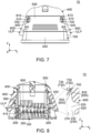
Fig. 7 is another front view showing the connector assembly ofFig. 2 . In the figure, the first connector and the second connector are in the mated state, and the lock lever is positioned at an unlock position. -
Fig. 8 is a cross-sectional view showing the connector assembly ofFig. 7 . In the figure, a part of the connector assembly is illustrated and enlarged. -
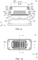
Fig. 9 is another front view showing the connector assembly ofFig. 2 . In the figure, the first connector and the second connector are in an unmated state where the first connector and the second connector are unmated with each other, and the lock lever is positioned at the lock position. -
Fig. 10 is a bottom view showing the connector assembly ofFig. 9 . -
Fig. 11 is a cross-sectional view showing the connector assembly ofFig. 10 , taken along line C-C. In the figure, a part of the first connector and a part of the second connector are enlarged and illustrated. -
Fig. 12 is a cross-sectional view showing the connector assembly ofFig. 10 , taken along line D-D. -
Fig. 13 is a front view showing the second connector which is included in the connector assembly ofFig. 9 . -
Fig. 14 is a cross-sectional view showing the second connector ofFig. 13 , taken along line E-E. In the figure, a part of the second connector is enlarged and illustrated. -
Fig. 15 is a bottom view showing the second connector ofFig. 13 . -
Fig. 16 is a side view showing the second connector ofFig. 13 . -
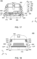
Fig. 17 is a cross-sectional view showing the second connector ofFig. 16 , taken along line F-F. In the figure, a part of the second connector is enlarged and illustrated. -
Fig. 18 is a front view showing the second connector which is included in the connector assembly ofFig. 7 . -
Fig. 19 is a bottom view showing the second connector ofFig. 18 . -
Fig. 20 is a side view showing the second connector ofFig. 18 . -
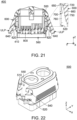
Fig. 21 is a cross-sectional view showing the second connector ofFig. 20 , taken along line G-G. In the figure, a part of the second connector is enlarged and illustrated. -
Fig. 22 is an upper, perspective view showing a part of a second housing which is included in the second connector ofFig. 13 . -
Fig. 23 is a front view showing the second housing ofFig. 22 . -
Fig. 24 is a side view showing the second housing ofFig. 22 . -
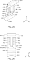
Fig. 25 is a perspective view showing the lock lever and a spring which are included in the second connector ofFig. 13 . -
Fig. 26 is a view showing the lock lever and the spring ofFig. 25 . -
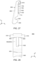
Fig. 27 is another view showing the lock lever and the spring ofFig. 25 . -
Fig. 28 is a view showing the lock lever which is included in the second connector ofFig. 13 . -
Fig. 29 is another view showing the lock lever ofFig. 28 . -
Fig. 30 is a perspective view showing the spring which is included in the second connector ofFig. 13 . The spring shown in the figure is in a state prior to attachment of the spring to both the second housing and the lock lever. -
Fig. 31 is a view showing the spring ofFig. 30 . -
Fig. 32 is another view showing the spring ofFig. 30 . -
Fig. 33 is an upper, perspective view showing the first connector which is included in the connector assembly ofFig. 1 . -
Fig. 34 is a top view showing the first connector ofFig. 33 . -
Fig. 35 is a side view showing the first connector ofFig. 33 . -
Fig. 36 is a front view showing a second connector which is included in a connector assembly according to a second embodiment of the present invention. -
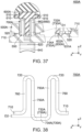
Fig. 37 is a cross-sectional view showing the second connector ofFig. 36 , taken along line H-H. In the figure, a part of the second connector is enlarged and illustrated. -
Fig. 38 is a view showing a spring which is included in the second connector ofFig. 37 . -
Fig. 39 is a view showing a modification of the spring ofFig. 38 . -
Fig. 40 is a front view showing a lever-type connector ofPatent Document 1. In the figure, a receptacle and a plug are in an unmated state where the receptacle and the plug are unmated with each other, and a lever is positioned at an unlock position. -
Fig. 41 is another front view showing the lever-type connector ofFig. 40 . In the figure, the receptacle and the plug are in a mated state where the receptacle and the plug are mated with each other, and the lever is positioned at a lock position. -
Fig. 42 is a perspective view showing the lever which is include in the lever-type connector ofFig. 41 . - While the invention is susceptible to various modifications and alternative forms, specific embodiments thereof are shown by way of example in the drawings and will herein be described in detail. It should be understood, however, that the drawings and detailed description thereto are not intended to limit the invention to the particular form disclosed, but on the contrary, the intention is to cover all modifications, equivalents and alternatives falling within the spirit and scope of the present invention as defined by the appended claims.
- As shown in
Fig. 9 , aconnector assembly 10 according to a first embodiment of the present invention comprises afirst connector 100 and asecond connector 400. - Referring to
Figs. 2 and9 , thefirst connector 100 of the present embodiment is mateable with thesecond connector 400 along a second direction and is removable from thesecond connector 400 along a first direction opposite to the second direction. In the present embodiment, the first direction is downward while the second direction is upward. In the figure, downward is shown as a negative Z-direction while upward is shown as a positive Z-direction. - As shown in
Fig. 33 , thefirst connector 100 comprises afirst housing 200 and a plurality offirst contacts 300. - Referring to
Fig. 33 , thefirst housing 200 of the present embodiment is made of insulator. As shown inFig. 11 , thefirst housing 200 is provided with two engagedportions 210. - As shown in
Fig. 11 , the engagedportions 210 of the present embodiment are positioned at opposite sides, respectively, of thefirst housing 200 in a width direction perpendicular to the first direction. In the present embodiment, the width direction is a Y-direction. Each of the engagedportions 210 is a surface facing in the first direction. In other words, each of the engagedportions 210 is the surface facing downward in an up-down direction. In the present embodiment, the up-down direction is a Z-direction. - As shown in
Fig. 11 , thefirst housing 200 is further provided with two intersectingportions 230. - As shown in
Fig. 11 , each of the intersectingportions 230 of the present embodiment has asurface 232 which intersects with the second direction. Thesurface 232 of the intersectingportion 230 neighbors to the engagedportion 210. The intersectingportions 230 correspond to the engagedportions 210, respectively. Thesurface 232 of each of the intersectingportions 230 neighbors to the corresponding engagedportion 210 in the width direction. Thesurface 232 of each of the intersectingportions 230 is positioned outward of the corresponding engagedportion 210 in the width direction. - As shown in
Fig. 33 , thefirst housing 200 is further provided with twosecond abutment portions 220. - As shown in
Fig. 11 , each of thesecond abutment portions 220 of the present embodiment faces in the second direction. In other words, each of thesecond abutment portions 220 faces upward in the up-down direction. Each of thesecond abutment portions 220 is a plane perpendicular to the second direction. Each of thesecond abutment portions 220 is positioned beyond any of the engagedportions 210 in the second direction. Thesecond abutment portions 220 correspond to the engagedportions 210, respectively. Each of thesecond abutment portions 220 is positioned beyond the corresponding the engagedportion 210 in the width direction. - As shown in
Fig. 33 , thefirst housing 200 has a matingportion accommodating portion 240. - As shown in
Fig. 33 , the matingportion accommodating portion 240 of the present embodiment is a recess which is recessed in the first direction. As shown inFig. 11 , the matingportion accommodating portion 240 is positioned between the two engagedportions 210 in the width direction. The matingportion accommodating portion 240 is positioned between the two intersectingportions 230 in the width direction. The matingportion accommodating portion 240 is positioned between the twosecond abutment portions 220 in the width direction. - Referring to
Fig. 34 , each of thefirst contacts 300 of the present embodiment is made of metal. Each of thefirst contacts 300 is held by thefirst housing 200. A part of each of thefirst contacts 300 is exposed in the matingportion accommodating portion 240. As shown inFig. 11 , each of the engagedportions 210 is positioned beyond any of thefirst contacts 300 in the second direction. In other words, each of the engagedportions 210 is positioned above any of thefirst contacts 300 in the up-down direction. Each of the intersectingportions 230 is positioned beyond any of thefirst contacts 300 in the second direction. In other words, each of the intersectingportions 230 is positioned above any of thefirst contacts 300 in the up-down direction. Each of thesecond abutment portions 220 is positioned beyond any of thefirst contacts 300 in the second direction. In other words, each of thesecond abutment portions 220 is positioned above any of thefirst contacts 300 in the up-down direction. - Referring to
Figs. 2 and9 , thesecond connector 400 of the present embodiment is mateable with thefirst connector 100 along the first direction and is removable from thefirst connector 100 along the second direction opposite to the first direction. As shown inFig. 13 , thesecond connector 400 has amating portion 410. - As shown in
Fig. 13 , themating portion 410 of the present embodiment is positioned at an end portion of thesecond connector 400 in the first direction. In other words, themating portion 410 of the present embodiment is positioned at a lower end of thesecond connector 400 in the up-down direction. Referring toFigs. 4 and11 , themating portion 410 is accommodated in the matingportion accommodating portion 240 of thefirst connector 100 when thefirst connector 100 and thesecond connector 400 are mated with each other. - As shown in
Figs. 13 and17 , thesecond connector 400 comprises asecond housing 500, twolock levers 600, twosprings 700 and a plurality ofsecond contacts 800. - Referring to
Fig. 22 , thesecond housing 500 of the present embodiment is made of insulator. Referring toFigs. 14 and23 , thesecond housing 500 is provided with fourfirst axis portions 510. - Referring to
Figs. 14 and22 , each of thefirst axis portions 510 of the present embodiment is abearing 510. Each of thefirst axis portions 510 is a hole extending in a front-rear direction perpendicular to the first direction. In the present embodiment, the front-rear direction is an X-direction. Specifically, it is assumed that forward is a positive X-direction while rearward is a negative X-direction. As shown inFig. 23 , each of thefirst axis portions 510 is positioned around an outer end of thesecond housing 500 in the width direction. The fourfirst axis portions 510 are grouped into two pairs each consisting of two of thefirst axis portions 510. The twofirst axis portions 510 of each pair are positioned at positions same as each other in the up-down direction. The twofirst axis portions 510 of each pair are positioned at positions same as each other in the width direction. - Referring to
Figs. 14 and23 , thesecond housing 500 is further provided with four holdingportions 520. - Referring to
Figs. 14 and23 , each of the holdingportions 520 of the present embodiment is a hole extending in the front-rear direction perpendicular to the first direction. The four holdingportions 520 are grouped into two pairs each consisting of two of the holdingportions 520. The two holdingportions 520 of each pair are positioned at positions same as each other in the up-down direction. The two holdingportions 520 of each pair are positioned at positions same as each other in the width direction. - Referring to
Figs. 23 and 24 , thesecond housing 500 is formed with fourditches 540. Each of theditches 540 is a hole extending in the front-rear direction. Theditch 540 communicates with thebearing 510 and extends in the first direction. Each of theditches 540 is positioned beyond any of the holdingportions 520 in the second direction. The fourditches 540 correspond to the fourbearings 510, respectively. Each of theditches 540 communicates with the correspondingbearing 510 and extends in the first direction. - Referring to
Figs. 23 and 24 , the four holdingportions 520, the fourfirst axis portions 510 and the fourditches 540 are grouped into two sets each consisting of two of the holdingportions 520, two of thefirst axis portions 510 and two of theditches 540. In each set, each of the holdingportions 520 is positioned beyond any of thefirst axis portions 510 in the first direction. In each set, each of the holdingportions 520 is positioned outward of any of thefirst axis portions 510 in the width direction. In each set, each of theditches 540 is positioned beyond any of thefirst axis portions 510 in the first direction. In each set, each of theditches 540 is positioned beyond any of the holdingportions 520 in the second direction. In each set, each of theditches 540 is positioned inward of any of the holdingportions 520 in the width direction. - Referring to
Figs. 8 and24 , thesecond housing 500 has two locklever accommodating portions 550. - Referring to
Figs. 8 and24 , the locklever accommodating portions 550 of the present embodiment are positioned at opposite sides, respectively, of thesecond housing 500 in the width direction. Each of the locklever accommodating portions 550 is recessed inward in the width direction. The two locklever accommodating portions 550 correspond to the two sets, respectively, each of which consists of the twofirst axis portions 510, the two holdingportions 520 and the twoditches 540. As shown inFig. 14 , each of the locklever accommodating portions 550 is positioned between the twofirst axis portions 510 of the corresponding set in the front-rear direction. Each of the locklever accommodating portions 550 is positioned between the two holdingportions 520 of the corresponding set in the front-rear direction. As shown inFig. 24 , each of the locklever accommodating portions 550 is positioned between the twoditches 540 of the corresponding set in the front-rear direction. - As shown in
Fig. 17 , thesecond housing 500 has a firstconnector accommodating portion 560. - As shown in
Fig. 11 , the firstconnector accommodating portion 560 of the present embodiment is recessed in the second direction. Referring toFigs. 4 and11 , the firstconnector accommodating portion 560 accommodates a part of thefirst connector 100 when thefirst connector 100 and thesecond connector 400 are mated with each other. - As understood from
Figs. 7 and13 , each of the lock levers 600 of the present embodiment is attached to thesecond housing 500 so as to be rotatable between a lock position LP and an unlock position ULP. The twolock levers 600 correspond to the two sets, respectively, each of which consists of the twofirst axis portions 510, the two holdingportions 520 and the twoditches 540. The twolock levers 600 correspond to the two locklever accommodating portions 550, respectively. As shown inFig. 14 , each of the lock levers 600 is accommodated in the corresponding locklever accommodating portion 550. - As shown in
Figs. 28 and29 , each of the lock levers 600 is provided with twosecond axis portions 610 and an engagingportion 620. - As shown in
Fig. 28 , each of thesecond axis portions 610 of the present embodiment is a rotation axis. Each of thesecond axis portions 610 extends in the front-rear direction. Each of thesecond axis portions 610 is positioned around an end portion of thelock lever 600 in the second direction. In other words, each of thesecond axis portions 610 is positioned around an upper end of thelock lever 600 in the up-down direction. As shown inFig, 14 , thesecond axis portion 610 is combined with thefirst axis portion 510. Specifically, the twosecond axis portions 610 of thelock lever 600 are combined with the twofirst axis portions 510, respectively, of the corresponding set. - As shown in
Fig. 29 , the engagingportion 620 of the present embodiment faces in the second direction. In other words, the engagingportion 620 faces upward in the up-down direction. The engagingportion 620 is a surface intersecting with the second direction. The engagingportion 620 is positioned beyond any of thesecond axis portions 610 in the first direction. In other words, the engagingportion 620 is positioned below any of thesecond axis portions 610 in the up-down direction. - As shown in
Fig. 4 , the engagingportion 620 is positioned beyond the engagedportion 210 in the first direction when thelock lever 600 is positioned at the lock position LP under a mated state where thefirst connector 100 and thesecond connector 400 are mated with each other. Specifically, the engagingportion 620 locks, together with the engagedportion 210, the mating of thefirst connector 100 with thesecond connector 400 when thelock lever 600 is positioned at the lock position LP under the mated state where thefirst connector 100 and thesecond connector 400 are mated with each other. - As shown in
Fig. 8 , thesecond connector 400 is removable from thefirst connector 100 when thelock lever 600 is positioned at the unlock position ULP under the mated state. In other words, the engagingportion 620 and the engagedportion 210 do not lock the mating of thefirst connector 100 with thesecond connector 400 when thelock lever 600 is positioned at the unlock position ULP under the mated state. - As shown in
Fig. 29 , thelock lever 600 is further provided with a first pressedportion 632 and a second pressedportion 634. - As shown in
Fig. 29 , the first pressedportion 632 of the present embodiment faces in the first direction. In other words, the first pressedportion 632 faces downward in the up-down direction. The first pressedportion 632 is positioned beyond any of thesecond axis portions 610 in the first direction. In other words, the first pressedportion 632 is positioned below any of thesecond axis portions 610 in the up-down direction. The first pressedportion 632 is positioned outward of any of thesecond axis portions 610 in the width direction. The first pressedportion 632 is positioned beyond the engagingportion 620 in the second direction. In other words, the first pressedportion 632 is positioned above the engagingportion 620 in the up-down direction. The first pressedportion 632 is positioned inward of the engagingportion 620 in the width direction. The first pressedportion 632 is positioned beyond the second pressedportion 634 in the second direction. In other words, the first pressedportion 632 is positioned above the second pressedportion 634 in the up-down direction. The first pressedportion 632 is positioned outward of the second pressedportion 634 in the width direction. As shown inFig. 14 , the first pressedportion 632 is positioned beyond any of the holdingportions 520 in the second direction. In other words, the first pressedportion 632 is positioned above any of the holdingportions 520 in the up-down direction. - Referring to
Figs. 11 and23 , when thelock lever 600 is positioned at the lock position LP, the first pressedportion 632 of thelock lever 600 is positioned at a position same as a position of any of the holdingportions 520 of the corresponding set in the width direction. Referring toFigs. 8 and23 , when thelock lever 600 is positioned at the unlock position ULP, the first pressedportion 632 of thelock lever 600 is positioned outward of any of the holdingportions 520 of the corresponding set in the width direction. - As shown in
Fig. 14 , the holdingportion 520 and the first pressedportion 632 are positioned away from each other by a first distance D1 in the second direction when thelock lever 600 is positioned at the lock position LP. In other words, the first distance D1 is a distance between the holdingportion 520 and the first pressedportion 632 in the second direction upon thelock lever 600 being positioned at the lock position LP. - As shown in
Fig. 29 , the second pressedportion 634 of the present embodiment faces outward in the width direction. The second pressedportion 634 is positioned beyond any of thesecond axis portions 610 in the first direction. In other words, the second pressedportion 634 is positioned below any of thesecond axis portions 610 in the up-down direction. The second pressedportion 634 is positioned outward of any of thesecond axis portions 610 in the width direction. The second pressedportion 634 is positioned beyond the engagingportion 620 in the second direction. In other words, the second pressedportion 634 is positioned above the engagingportion 620 in the up-down direction. The second pressedportion 634 is positioned inward of the engagingportion 620 in the width direction. The second pressedportion 634 is positioned beyond the first pressedportion 632 in the first direction. In other words, the second pressedportion 634 is positioned below the first pressedportion 632 in the up-down direction. The second pressedportion 634 is positioned inward of the first pressedportion 632 in the width direction. Referring toFigs. 4 and14 , the second pressedportion 634 is positioned beyond any of the holdingportions 520 in the second direction. In other words, the second pressedportion 634 is positioned above any of the holdingportions 520 in the up-down direction. - As shown in
Fig. 28 , thelock lever 600 is provided with two regulatingportions 650. However, the present invention is not limited thereto, but the regulatingportion 650 may be provided at thesecond housing 500. In other words, one of thesecond housing 500 and thelock lever 600 should be provided with the regulatingportion 650. - As shown in
Fig. 29 , each of the regulatingportions 650 of the present embodiment is a surface facing inward in the width direction. Each of the regulatingportions 650 is positioned beyond any of thesecond axis portions 610 in the first direction. In other words, each of the regulatingportions 650 is positioned below any of thesecond axis portions 610 in the up-down direction. Each of the regulatingportions 650 is positioned outward of any of thesecond axis portions 610 in the width direction. Each of the regulatingportions 650 is positioned beyond the engagingportion 620 in the second direction. In other words, each of the regulatingportions 650 is positioned above the engagingportion 620 in the up-down direction. Each of the regulatingportions 650 is positioned inward of the engagingportion 620 in the width direction. Referring toFigs. 18 ,21 and29 , each of the regulatingportions 650 of thelock lever 600 is positioned outward of any of thefirst axis portions 510 of the corresponding set in the width direction. - As shown in
Fig. 28 , thelock lever 600 is further provided with a hookedportion 630. - As shown in
Fig. 28 , the hookedportion 630 of the present embodiment is positioned at a middle of thelock lever 600 in the front-rear direction. The hookedportion 630 is positioned between the twosecond axis portions 610 in the front-rear direction. The hookedportion 630 is positioned around a middle of thelock lever 600 in the up-down direction. As shown inFig. 29 , the hookedportion 630 is positioned beyond any of thesecond axis portions 610 in the first direction. In other words, the hookedportion 630 is positioned below any of thesecond axis portions 610 in the up-down direction. The hookedportion 630 is positioned beyond the engagingportion 620 in the second direction. In other words, the hookedportion 630 is positioned above the engagingportion 620 in the up-down direction. The hookedportion 630 has a recessedportion 631. The recessedportion 631 is recessed in the second direction. In other words, the recessedportion 631 is recessed upward in the up-down direction. The recessedportion 631 communicates with the outside of the hookedportion 630 in the front-rear direction. Each of the first pressedportion 632 and the second pressedportion 634 is provided on the hookedportion 630. More specifically, a surface, which faces in the first direction, of the recessedportion 631 of the hookedportion 630 functions as the first pressedportion 632, and a surface, which faces outward in the width direction, of the recessedportion 631 of the hookedportion 630 functions as the second pressedportion 634. - Although the hooked
portion 630 of the present embodiment has the recessedportion 631, the present invention is not limited thereto. Specifically, the hookedportion 630 may have, instead of the recessedportion 631, a hole which pierces the hookedportion 630 in the front-rear direction. In this case, an inner surface, which faces in the first direction, of the hole of the hookedportion 630 functions as the first pressedportion 632, and an inner surface, which faces outward in the width direction, of the hole of the hookedportion 630 functions as the second pressedportion 634. - As shown in
Fig. 29 , thelock lever 600 is further provided with afirst abutment portion 640. Specifically, theconnector assembly 10 of the present embodiment has two sets each consisting of thelock lever 600, the engagingportion 620, thefirst abutment portion 640, thespring 700, the engagedportion 210 and thesecond abutment portion 220. However, the present invention is not limited thereto, but theconnector assembly 10 should have a single set of thelock lever 600, the engagingportion 620, thefirst abutment portion 640, thespring 700, the engagedportion 210 and thesecond abutment portion 220. - As shown in
Fig. 29 , thefirst abutment portion 640 of the present embodiment is positioned beyond the engagingportion 620 in the first direction. In other words, thefirst abutment portion 640 is positioned below the engagingportion 620 in the up-down direction. Thefirst abutment portion 640 is positioned at an end portion of thelock lever 600 in the first direction. In other words, thefirst abutment portion 640 is positioned at a lower end of thelock lever 600 in the up-down direction. Thefirst abutment portion 640 is an inclined surface oblique to the first direction. Specifically, thefirst abutment portion 640 faces in the first direction and inward in the width direction. In other words, thefirst abutment portion 640 faces downward in the up-down direction and inward in the width direction. - Although the
connector assembly 10 of the present embodiment is configured so that thesecond abutment portion 220 is the plane perpendicular to the second direction, while thefirst abutment portion 640 is the inclined surface oblique to the first direction, the present invention is not limited thereto. Specifically, theconnector assembly 10 may be configured so that thesecond abutment portion 220 is an inclined surface oblique to the first direction, while thefirst abutment portion 640 is a plane perpendicular to the second direction. In other words, at least one of thefirst abutment portion 640 and thesecond abutment portion 220 should be an inclined surface which is oblique to the first direction; - As shown in
Fig. 29 , thelock lever 600 further has amain portion 660. - As shown in
Fig. 29 , themain portion 660 of the present embodiment defines an outer end of thelock lever 600 in the width direction. Themain portion 660 has aninner surface 662. Theinner surface 662 faces inward in the width direction. Theinner surface 662 is positioned outward of any of thesecond axis portions 610 in the width direction. Theinner surface 662 is positioned outward of the hookedportion 630 in the width direction. The hookedportion 630 protrudes inward in the width direction from themain portion 660. As shown inFig. 28 , each of the regulatingportions 650 is provided on themain portion 660. More specifically, each of the regulatingportions 650 is a part of theinner surface 662 of themain portion 660. - Referring to
Fig. 31 , thespring 700 of the present embodiment is made of metal. Thespring 700 is formed by bending a round metal rod. As shown inFig. 14 , thespring 700 is attached to both thesecond housing 500 and thelock lever 600. - Referring to
Figs. 11 ,14 and21 , thespring 700 urges thelock lever 600 to be moved toward the lock position LP, and thespring 700 urges thesecond axis portions 610 to be moved in the second direction when thelock lever 600 is positioned at the lock position LP. In other words, thespring 700 urges thelock lever 600 to be moved toward the lock position LP, and thespring 700 urges thesecond axis portions 610 to be moved upward in the up-down direction when thelock lever 600 is positioned at the lock position LP. - As described above, the
connector assembly 10 of the present embodiment is configured as follows: the engagingportion 620 of thelock lever 600 is positioned beyond the engagedportion 210 of thefirst housing 200 in the first direction when thelock lever 600 is positioned at the lock position LP under the mated state where thefirst connector 100 and thesecond connector 400 are mated with each other; thespring 700 is attached to both thesecond housing 500 and thelock lever 600; thespring 700 urges thelock lever 600 to be moved toward the lock position LP; and, when thelock lever 600 is positioned at the lock position LP, thespring 700 urges thesecond axis portions 610 to be moved in the second direction. Accordingly, when thelock lever 600 is positioned at the lock position LP under the mated state where thefirst connector 100 and thesecond connector 400 are mated with each other, the engagingportion 620 of thelock lever 600 is pressed against the engagedportion 210 of thefirst housing 200 of thefirst connector 100 and thereby both components of thefirst connector 100 and thesecond connector 400 are prevented from being unstable. Specifically, theconnector assembly 10 of the present embodiment prevents the both components of thefirst connector 100 and thesecond connector 400, which are mated with each other, from being unstable when theconnector assembly 10 is used in a high vibration environment. - As shown in
Fig. 31 , thespring 700 has a substantially M-shape when thespring 700 is viewed alone in the width direction. Thespring 700 has two heldportions 710, tworegulated portions 720, a firstpressing portion 732, a secondpressing portion 734 and twoarm portions 750. However, the present invention is not limited thereto, but the number of each of the heldportion 710, theregulated portion 720 and thearm portion 750 may be one. In other words, thespring 700 should have the single heldportion 710, the singleregulated portion 720, the firstpressing portion 732, the secondpressing portion 734 and thesingle arm portion 750. - As shown in
Fig. 31 the heldportions 710 of the present embodiment define opposite ends, respectively, of thespring 700 in the front-rear direction. As shown inFig. 14 , the heldportion 710 is held by the holdingportion 520. As shown inFig. 26 , the hookedportion 630 is positioned between the two heldportions 710 in the front-rear direction. - As shown in
Fig. 31 , each of theregulated portions 720 of the present embodiment is positioned at an end portion of thespring 700 in the second direction. In other words, each of theregulated portions 720 of the present embodiment is positioned at an upper end of thespring 700 in the up-down direction. Referring toFigs. 17 and21 , at least when thelock lever 600 is moved from the lock position LP toward the unlock position ULP, a movement of theregulated portion 720 is regulated by the regulatingportion 650. As shown inFig. 26 , the hookedportion 630 is positioned between the tworegulated portions 720 in the front-rear direction. - Although the regulating
portion 650 of the present embodiment is the surface, which faces inward in the width direction, and regulates the movement of theregulated portion 720 at least when thelock lever 600 is moved from the lock position LP toward the unlock position ULP, the present invention is not limited thereto. Specifically, the regulatingportion 650 may have any structure, provided that the regulatingportion 650 regulates the movement of theregulated portion 720 at least when thelock lever 600 is moved from the lock position LP toward the unlock position ULP. More specifically, the regulatingportion 650 may be, for example, a recess which is recessed in the second direction, or upward in the up-down direction, and which, at least in part, accommodates theregulated portion 720. - As shown in
Fig. 31 , the firstpressing portion 732 of the present embodiment faces in the second direction. In other words, the firstpressing portion 732 faces upward in the up-down direction. The firstpressing portion 732 is positioned at a middle of thespring 700 in the front-rear direction. The firstpressing portion 732 is positioned beyond any of theregulated portions 720 in the first direction. In other words, the firstpressing portion 732 is positioned below any of theregulated portions 720 in the up-down direction. The firstpressing portion 732 is positioned beyond any of the heldportions 710 in the second direction. In other words, the firstpressing portion 732 is positioned above any of the heldportions 710 in the up-down direction. When thespring 700 is viewed alone, the heldportion 710 and the firstpressing portion 732 are positioned away from each other by a second distance D2 in the second direction. In other words, the second distance D2 is a distance between the heldportion 710 and the firstpressing portion 732 in the second direction upon thespring 700 being viewed alone. - As shown in
Figs. 13 and 14 , each of the heldportions 710 is positioned beyond the firstpressing portion 732 in the first direction when thelock lever 600 is positioned at the lock position LP. In other words, each of the heldportions 710 is positioned below the firstpressing portion 732 in the up-down direction when thelock lever 600 is positioned at the lock position LP. - Referring to
Fig. 14 , when thelock lever 600 is positioned at the lock position LP, the firstpressing portion 732 is positioned beyond the first pressedportion 632 in the first direction while the firstpressing portion 732 presses the first pressedportion 632 in the second direction. In other words, when thelock lever 600 is positioned at the lock position LP, the firstpressing portion 732 is positioned below the first pressedportion 632 in the up-down direction while the firstpressing portion 732 presses the first pressedportion 632 upward in the up-down direction. - Referring to
Figs. 14 and31 , in thesecond connector 400 of the present embodiment, the first distance D1 is shorter than the second distance D2. Specifically, in thesecond connector 400 of the present embodiment which is configured so that the heldportion 710 is positioned beyond the firstpressing portion 732 in the first direction when thelock lever 600 is positioned at the lock position LP, the first distance D1 is shorter than the second distance D2. Accordingly, when thespring 700 is attached to both thesecond housing 500 and thelock lever 600, the first pressedportion 632 of thelock lever 600 presses the firstpressing portion 732 of thespring 700 in the first direction, or downward in the up-down direction, and thereby thespring 700 is resiliently deformed to have a restoring force. Then, the restoring force generated by the resilient deformation of thespring 700 causes the firstpressing portion 732 of thespring 700 to apply a force, which urges the first pressedportion 632 of thelock lever 600 to be moved in the second direction, or upward in the up-down direction, to the first pressedportion 632 of thelock lever 600. - Referring to
Fig. 13 , in a natural state, thelock lever 600 of thesecond connector 400 is configured to be positioned at the lock position LP. When an operator pulls the first directional end portion, or the lower end in the up-down direction, of thelock lever 600 in its natural state, thespring 700 is resiliently deformed to have a restoring force, while thesecond axis portion 610 is moved from thefirst axis portion 510 into theditch 540 so that thelock lever 600 is slightly moved relative to thesecond housing 500 in the first direction, or downward in the up-down direction. When the operator stops the pulling of its end portion, the restoring force generated by the resilient deformation of thespring 700 moves thesecond axis portion 610 from theditch 540 into thefirst axis portion 510 and moves thelock lever 600 in the second direction, or upward in the up-down direction, so that thelock lever 600 returns to its initial position. - As shown in
Fig. 31 , the secondpressing portion 734 of the present embodiment is positioned at the middle of thespring 700 in the front-rear direction. The secondpressing portion 734 is positioned beyond any of theregulated portions 720 in the first direction. In other words, the secondpressing portion 734 is positioned below any of theregulated portions 720 in the up-down direction. The secondpressing portion 734 is positioned beyond any of the heldportions 710 in the second direction. In other words, the secondpressing portion 734 is positioned above any of the heldportions 710 in the up-down direction. As shown inFig. 11 , the secondpressing portion 734 faces inward in the width direction. The secondpressing portion 734 neighbors to the second pressedportion 634 in a direction perpendicular to the first direction. Specifically, the secondpressing portion 734 neighbors to the second pressedportion 634 in the width direction perpendicular to the first direction. The secondpressing portion 734 is positioned outward of the second pressedportion 634 in the width direction. - As shown in
Fig. 31 , thearm portions 750 of the present embodiment extend in the first direction from theregulated portions 720, respectively. In other words, each of thearm portions 750 extends downward in the up-down direction from the correspondingregulated portion 720. Thearm portions 750 extend in the second direction from the secondpressing portion 734. In other words, each of thearm portions 750 extends upward in the up-down direction from the secondpressing portion 734. Thearm portion 750 couples the secondpressing portion 734 and theregulated portion 720 with each other. As shown inFig. 26 , the hookedportion 630 is positioned between the twoarm portions 750 in the front-rear direction. - Referring to
Figs. 8 ,11 ,17 and21 , when thelock lever 600 is moved from the lock position LP toward the unlock position ULP, the secondpressing portion 734 is moved together with the second pressedportion 634 and mainly thearm portions 750 are resiliently deformed so that each of thearm portions 750 has a restoring force. The restoring force generated by the resilient deformation of each of thearm portions 750 causes the secondpressing portion 734 to press the second pressedportion 634 and to move thelock lever 600 toward the lock position LP. - As shown in
Fig. 31 , thespring 700 further has apressing section 730. - As shown in
Fig. 31 , thepressing section 730 of the present embodiment is positioned at the middle of thespring 700 in the front-rear direction. Thepressing section 730 is positioned beyond any of theregulated portions 720 in the first direction. In other words, thepressing section 730 is positioned below any of theregulated portions 720 in the up-down direction. Thepressing section 730 is positioned beyond any of the heldportions 710 in the second direction. In other words, thepressing section 730 is positioned above any of the heldportions 710 in the up-down direction. Each of the firstpressing portion 732 and the secondpressing portion 734 is a part of thepressing section 730. As shown inFig. 25 , thepressing section 730 is hooked on the hookedportion 630. Specifically, thepressing section 730 is hooked on the recessedportion 631 of the hookedportion 630. - As described above, the
connector assembly 10 of the present embodiment is configured as follows: the hookedportion 630 has the recessedportion 631 which is recessed in the second direction; thespring 700 has the substantially M-shape when thespring 700 is viewed alone in the width direction; and thepressing section 730 of thespring 700 is hooked on the recessedportion 631 of the hookedportion 630. Accordingly, thespring 700 is easily attached to thelock lever 600 upon assembly of thesecond connector 400 of the present embodiment. - As shown in
Fig. 31 , thespring 700 further has twocoupling portions 760. - As shown in
Fig. 31 , thecoupling portions 760 of the present embodiment extend in the first direction from theregulated portions 720, respectively. In other words, each of thecoupling portions 760 extends downward in the up-down direction from the correspondingregulated portion 720. Thecoupling portions 760 extend in the second direction from the heldportions 710, respectively. In other words, each of thecoupling portions 760 extends upward in the up-down direction from the corresponding heldportion 710. Thecoupling portion 760 couples theregulated portion 720 and the heldportion 710 with each other. As shown inFig. 26 , the hookedportion 630 is positioned between the twocoupling portions 760 in the front-rear direction. - Referring to
Fig. 11 , each of thesecond contacts 800 of the present embodiment is made of metal. As shown inFig. 4 , thesecond contacts 800 of thesecond connector 400 are connected with thefirst contacts 300, respectively, of thefirst connector 100 under the mated state where thefirst connector 100 and thesecond connector 400 are mated with each other. - Hereinafter, a detailed description will be made about an operation of mating the
first connector 100 with thesecond connector 400. - First, referring to
Figs. 9 and11 , thesecond connector 400 is arranged beyond thefirst connector 100 in the second direction, or above thefirst connector 100 in the up-down direction. From this state, thesecond connector 400 is moved relative to thefirst connector 100 in the first direction, or downward in the up-down direction. Then, a part of themating portion 410 of thesecond connector 400 is accommodated in the matingportion accommodating portion 240 of thefirst connector 100 while thefirst abutment portion 640 of thelock lever 600 of thesecond connector 400 abuts against thesecond abutment portion 220 of thefirst connector 100. - From this state, the
second connector 400 is further moved in the first direction relative to thefirst connector 100. Then, thefirst abutment portion 640, which is the inclined surface oblique to the first direction, receives an outward force in the width direction from thesecond abutment portion 220, and thelock lever 600 is moved from the lock position LP to the unlock position ULP. Meanwhile, the secondpressing portion 734 is moved together with the second pressedportion 634 and mainly thearm portions 750 are resiliently deformed so that each of thearm portions 750 has the restoring force, and thesecond axis portion 610 is slightly moved from the bearing 510 into theditch 540 against thespring 700. - After that, the
second connector 400 is further moved in the first direction relative to thefirst connector 100. Then, thefirst abutment portion 640 rides over thesecond abutment portion 220 to be moved beyond thesecond abutment portion 220 in the first direction, and the engagingportion 620 is moved beyond the engagedportion 210 in the first direction. Meanwhile, thesecond axis portion 610, which has already been moved into theditch 540, receives, from thespring 700, a force which is directed in the second direction, or upward in the up-down direction. Also meanwhile, the restoring force generated by the resilient deformation of each of thearm portions 750 causes the secondpressing portion 734 to press the second pressedportion 634 and to move thelock lever 600 from the unlock position ULP to the lock position LP. Thus, theconnector assembly 10 changes its state into a state shown inFig. 4 where thefirst connector 100 and thesecond connector 400 are mated with each other while the mated state of thefirst connector 100 with thesecond connector 400 is locked. In this state, thelock lever 600 is positioned at the lock position LP, and thesecond contacts 800 are connected with thefirst contacts 300, respectively. Also, in this state, the engagingportion 620 is pressed against the engagedportion 210 in the second direction, or upward in the up-down direction. - The above operation is summarized as follows: when the
first connector 100 and thesecond connector 400 are mated with each other, thefirst abutment portion 640, which is the inclined surface oblique to the first direction, abuts against thesecond abutment portion 220 and thelock lever 600 is temporarily moved from the lock position LP to the unlock position ULP; and, when thefirst abutment portion 640 rides over thesecond abutment portion 220, the engagingportion 620 is moved beyond the engagedportion 210 in the first direction. - As described above, the
connector assembly 10 of the present embodiment is configured so that thefirst abutment portion 640 is the inclined surface oblique to the first direction. Accordingly, in theconnector assembly 10 of the present embodiment, each of the lock levers 600 is temporarily and automatically moved from the lock position LP to the unlock position ULP by simply moving thesecond connector 400 in the first direction relative to thefirst connector 100 upon the mating of thefirst connector 100 with thesecond connector 400. In other words, the operator does not need to operate the lock levers 600 upon the mating of thefirst connector 100 with thesecond connector 400. - As described above, upon the mating of the
first connector 100 with thesecond connector 400, thesecond axis portion 610 is not only received in thebearing 510 but is also movable into theditch 540 which communicates with thebearing 510. Accordingly, when thelock lever 600 is moved from the lock position LP to the unlock position ULP, thelock lever 600 can be temporarily moved in the first direction, or downward in the up-down direction, while thespring 700 can be temporarily further resiliently deformed. Thus, theconnector assembly 10 of the present embodiment is configured so that the restoring force generated by the resilient deformation of thespring 700 can more strongly press the engagingportion 620 against the engagedportion 210 in the second direction, or upward in the up-down direction, upon completion of the mating of thefirst connector 100 with thesecond connector 400. - Hereinafter, a detailed description will be made about an operation of releasing the mating of the
first connector 100 with thesecond connector 400. - First, in the
connector assembly 10 under the state shown inFig. 4 , the operator pulls the first directional end portion of thelock lever 600 of thesecond connector 400 outward in the width direction. Then, the secondpressing portion 734 is moved together with the second pressedportion 634 and mainly thearm portions 750 are resiliently deformed, and thereby the engagingportion 620 of thelock lever 600 is brought into contact with thesurface 232, which neighbors to the engagedportion 210 in the width direction, of the intersectingportion 230. - From this state, the operator slightly pulls the first directional end portion of the
lock lever 600 outward in the width direction. Then, mainly thearm portions 750 are further resiliently deformed, and the engagingportion 620 of thelock lever 600 is moved outward in the width direction, and thereby thelock lever 600 is moved to the unlock position ULP. Thus, theconnector assembly 10 changes its state into a state shown inFig. 8 where the lock of the mating of thefirst connector 100 with thesecond connector 400 is released. - As described above, the
first connector 100 of the present embodiment has the intersectingportion 230 which neighbors to the engagedportion 210 in the width direction and whosesurface 232 intersects with the second direction. Thus, in theconnector assembly 10 of the present embodiment, the lock of the mating of thefirst connector 100 with thesecond connector 400 can be easily released by slightly pulling the first directional end portion of thelock lever 600 outward in the width direction. - Finally, in the
connector assembly 10 under the state shown inFig. 8 , thesecond connector 400 is moved relative to thefirst connector 100 in the second direction, or upward in the up-down direction. Then, the mating of thefirst connector 100 with thesecond connector 400 is released. When the operator removes his/her hand from the lock levers 600 in this state, each of the lock levers 600 is moved from the unlock position ULP to the lock position LP by the restoring force generated by the resilient deformation of each of thearm portions 750 of thespring 700. Thus, theconnector assembly 10 changes its state into a state shown inFig. 9 , and the operation of releasing the mating of thefirst connector 100 with thesecond connector 400 is completed - Referring to
Fig. 36 , a connector assembly (not shown) according to a second embodiment of the present invention comprises a first connector (not shown) and asecond connector 400A. The first connector of the present embodiment has a structure same as that of thefirst connector 100 of the aforementioned first embodiment. Accordingly, a detailed explanation thereabout is omitted. As for directions and orientations in the present embodiment, expressions same as those of the first embodiment will be used hereinbelow. - Referring to
Fig. 36 , thesecond connector 400A of the present embodiment is mateable with the first connector along the first direction and is removable from the first connector along the second direction opposite to the first direction. As shown inFig. 36 , thesecond connector 400A has amating portion 410. Themating portion 410 of the present embodiment has a structure same as that of themating portion 410 of the aforementioned first embodiment. Accordingly, a detailed explanation thereabout is omitted. - Referring to
Fig. 36 , thesecond connector 400A comprises asecond housing 500A, twolock levers 600A, twosprings 700A and a plurality of second contacts (not shown). The second contact of the present embodiment has a structure same as that of thesecond contact 800 of the aforementioned first embodiment. Accordingly, a detailed explanation thereabout is omitted. Thesecond housing 500A of the present embodiment has a structure similar to that of thesecond housing 500 of the aforementioned first embodiment. Accordingly, components of thesecond housing 500A shown inFigs. 36 and37 which are same as those of thesecond housing 500 of the first embodiment are referred by using reference signs same as those of thesecond housing 500 of the first embodiment, and a detailed explanation thereabout is omitted. It is noted that, similar to thesecond connector 400 of the aforementioned first embodiment, thesecond connector 400A of the present embodiment is also configured so that fourfirst axis portions 510, four holdingportions 520 and fourditches 540 are grouped into two sets each consisting of two of thefirst axis portions 510, two of the holdingportions 520 and two of theditches 540. - Referring to
Fig. 36 , each of the lock levers 600A of the present embodiment is attached to thesecond housing 500A so as to be rotatable between a lock position LP and an unlock position (not shown). The twolock levers 600A correspond to the two sets, respectively, each of which consists of the twofirst axis portions 510, the two holdingportions 520 and the twoditches 540. - Referring to
Figs. 36 and37 , thelock lever 600A of the present embodiment has a structure similar to that of thelock lever 600 of the aforementioned first embodiment except for ahooked portion 630A. Accordingly, components of thelock lever 600A shown inFigs. 36 and37 which are same as those of thelock lever 600 of the first embodiment are referred by using reference signs same as those of thelock lever 600 of the first embodiment, and a detailed explanation thereabout is omitted. - Referring to
Fig. 36 , when thelock lever 600A is positioned at the lock position LP under a mated state where the first connector and thesecond connector 400A are mated with each other, an engagingportion 620 of thelock lever 600A is positioned beyond an engaged portion of the first connector in the first direction. Thesecond connector 400A is removable from the first connector when thelock lever 600A is positioned at the unlock position under the mated state. - Referring to
Fig. 36 , the connector assembly of the present embodiment has two sets each consisting of thelock lever 600A, the engagingportion 620, afirst abutment portion 640, thespring 700A, the engaged portion of the first connector and a second abutment portion of the first connector. However, the present invention is not limited thereto, but the connector assembly should have a single set of thelock lever 600A, the engagingportion 620, thefirst abutment portion 640, thespring 700A, the engaged portion and the second abutment portion. - As shown in
Fig. 37 , the hookedportion 630A of the present embodiment is positioned at a middle of thelock lever 600A in the front-rear direction. The hookedportion 630A is positioned between twosecond axis portions 610 in the front-rear direction. The hookedportion 630A is positioned around a middle of thelock lever 600A in the up-down direction. Referring toFigs. 36 and37 , the hookedportion 630A is positioned beyond any of thesecond axis portions 610 in the first direction. In other words, the hookedportion 630A is positioned below any of thesecond axis portions 610 in the up-down direction. The hookedportion 630A is positioned beyond the engagingportion 620 in the second direction. In other words, the hookedportion 630A is positioned above the engagingportion 620 in the up-down direction. The hookedportion 630A has a recessedportion 631A. The recessedportion 631A is recessed in the second direction. In other words, the recessedportion 631A is recessed upward in the up-down direction. The recessedportion 631A communicates with the outside of the hookedportion 630A in the front-rear direction. The hookedportion 630A is provided with a first pressedportion 632A and a second pressed portion (not shown). More specifically, a surface, which faces in the first direction, of the recessedportion 631A of the hookedportion 630A functions as the first pressedportion 632A, and a surface, which faces outward in the width direction, of the recessedportion 631A of the hookedportion 630A functions as the second pressed portion. The second pressed portion of the present embodiment has a structure same as that of the second pressedportion 634 of the aforementioned first embodiment. Accordingly, a detailed explanation thereabout is omitted. - Although the hooked
portion 630A of the present embodiment has the recessedportion 631A, the present invention is not limited thereto. Specifically, the hookedportion 630A may have, instead of the recessedportion 631A, a hole which pierces the hookedportion 630A in the front-rear direction. In this case, an inner surface, which faces in the first direction, of the hole of the hookedportion 630A functions as the first pressedportion 632A, and an inner surface, which faces outward in the width direction, of the hole of the hookedportion 630A functions as the second pressed portion. - As shown in
Fig. 37 , the first pressedportion 632A of the present embodiment faces in the first direction. In other words, the first pressedportion 632A faces downward in the up-down direction. The first pressedportion 632A is positioned beyond any of thesecond axis portions 610 in the first direction. In other words, the first pressedportion 632A is positioned below any of thesecond axis portions 610 in the up-down direction. The first pressedportion 632A is positioned beyond the engagingportion 620 in the second direction. In other words, the first pressedportion 632A is positioned above the engagingportion 620 in the up-down direction. The first pressedportion 632A is positioned beyond any of the holdingportions 520 in the first direction. In other words, the first pressedportion 632A is positioned below any of the holdingportions 520 in the up-down direction. Referring toFig. 37 , the first pressedportion 632A is positioned beyond the second pressed portion in the second direction. In other words, the first pressedportion 632A is positioned above the second pressed portion in the up-down direction. Referring toFigs. 36 and37 , the first pressedportion 632A is positioned outward of any of thesecond axis portions 610 in the width direction. The first pressedportion 632A is positioned inward of the engagingportion 620 in the width direction. The first pressedportion 632A is positioned outward of the second pressed portion in the width direction. - Referring to
Figs. 36 and37 , when thelock lever 600A is positioned at the lock position LP, the first pressedportion 632A of thelock lever 600A is positioned at a position same as a position of any of the holdingportions 520 of the corresponding set in the width direction. When thelock lever 600 is positioned at the unlock position ULP, the first pressedportion 632A of thelock lever 600A is positioned outward of any of the holdingportions 520 of the corresponding set in the width direction. - As shown in
Fig. 37 , the holdingportion 520 and the first pressedportion 632A are positioned away from each other by a first distance D1 in the second direction when thelock lever 600A is positioned at the lock position LP. In other words, the first distance D1 is a distance between the holdingportion 520 and the first pressedportion 632A in the second direction upon thelock lever 600A being positioned at the lock position LP. - Referring to
Fig. 38 , thespring 700A of the present embodiment is made of metal. Thesprings 700A is formed by bending a round metal rod. As shown inFig. 37 , thespring 700A is attached to both thesecond housing 500A and thelock lever 600A. - Referring to
Figs. 36 and37 , thespring 700A urges thelock lever 600A to be moved toward the lock position LP, and thespring 700A urges thesecond axis portions 610 to be moved in the second direction when thelock lever 600A is positioned at the lock position LP. In other words, thespring 700A urges thelock lever 600A to be moved toward the lock position LP, and thespring 700A urges thesecond axis portions 610 to be moved upward in the up-down direction when thelock lever 600A is positioned at the lock position LP. - As described above, the connector assembly of the present embodiment is configured as follows: the engaging
portion 620 of thelock lever 600A is positioned beyond the engaged portion of the first housing in the first direction when thelock lever 600A is positioned at the lock position LP under the mated state where the first connector and thesecond connector 400A are mated with each other; thespring 700A is attached to both thesecond housing 500A and thelock lever 600A; thespring 700A urges thelock lever 600A to be moved toward the lock position LP; and, when thelock lever 600A is positioned at the lock position LP, thespring 700A urges thesecond axis portions 610 to be moved in the second direction. Accordingly, when thelock lever 600A is positioned at the lock position LP under the mated state where the first connector and thesecond connector 400A are mated with each other, the engagingportion 620 of thelock lever 600A is pressed against the engaged portion of the first housing of the first connector and thereby both components of the first connector and thesecond connector 400 are prevented from being unstable. Specifically, the connector assembly of the present embodiment prevents the both components of the first connector and thesecond connector 400A, which are mated with each other, from being unstable when the connector assembly is used in a high vibration environment. - As shown in
Fig. 38 , thespring 700A has a substantially M-shape when thespring 700A is viewed alone in the width direction. Thespring 700A has two heldportions 710, tworegulated portions 720, a firstpressing portion 732A, a secondpressing portion 734A and twoarm portions 750A. However, the present invention is not limited thereto, but the number of each of the heldportion 710, theregulated portion 720 and thearm portion 750A may be one. In other words, thespring 700A should have the single heldportion 710, the singleregulated portion 720, the firstpressing portion 732A, the secondpressing portion 734A and thesingle arm portion 750A. - The
spring 700A of the present embodiment has a structure similar to that of thespring 700 of the aforementioned first embodiment except for the firstpressing portion 732A and the secondpressing portion 734A and thearm portions 750A. Accordingly, a detailed explanation about components of thespring 700A other than the firstpressing portion 732A, the secondpressing portion 734A and thearm portion 750A is omitted. - As shown in
Fig. 38 , the firstpressing portion 732A of the present embodiment faces in the second direction. In other words, the firstpressing portion 732A faces upward in the up-down direction. The firstpressing portion 732A is positioned at a middle of thespring 700A in the front-rear direction. The firstpressing portion 732A is positioned beyond any of theregulated portions 720 in the first direction. In other words, the firstpressing portion 732A is positioned below any of theregulated portions 720 in the up-down direction. The firstpressing portion 732A is positioned beyond any of the heldportions 710 in the first direction. In other words, the firstpressing portion 732A is positioned below any of the heldportions 710 in the up-down direction. When thespring 700A is viewed alone, the heldportion 710 and the firstpressing portion 732A are positioned away from each other by a second distance D2 in the second direction. In other words, the second distance D2 is a distance between the heldportion 710 and the firstpressing portion 732A in the second direction upon thespring 700A being viewed alone. - As shown in
Fig. 37 , each of the heldportions 710 is positioned beyond the firstpressing portion 732A in the second direction when thelock lever 600A is positioned at the lock position LP. In other words, each of the heldportions 710 is positioned above the firstpressing portion 732A in the up-down direction when thelock lever 600A is positioned at the lock position LP. - Referring to
Fig. 37 , when thelock lever 600A is positioned at the lock position LP, the firstpressing portion 732A is positioned beyond the first pressedportion 632A in the first direction while the firstpressing portion 732A presses the first pressedportion 632A in the second direction. In other words, when thelock lever 600A is positioned at the lock position LP, the firstpressing portion 732A is positioned below the first pressedportion 632A in the up-down direction while the firstpressing portion 732A presses the first pressedportion 632A upward in the up-down direction. - Referring to
Figs. 37 and 38 , in thesecond connector 400A of the present embodiment, the first distance D1 is longer than the second distance D2. Specifically, in thesecond connector 400A of the present embodiment which is configured so that the heldportion 710 is positioned beyond the firstpressing portion 732A in the second direction when thelock lever 600A is positioned at the lock position LP, the first distance D1 is longer than the second distance D2. Accordingly, when thespring 700A is attached to both thesecond housing 500A and thelock lever 600A, the first pressedportion 632A of thelock lever 600A presses the firstpressing portion 732A of thespring 700A in the first direction, or downward in the up-down direction, and thereby thespring 700A is resiliently deformed to have a restoring force. Then, the restoring force generated by the resilient deformation of thespring 700A causes the firstpressing portion 732A of thespring 700A to apply a force, which urges the first pressedportion 632A of thelock lever 600A to be moved in the second direction, or upward in the up-down direction, to the first pressedportion 632A of thelock lever 600A. - As shown in
Fig. 38 , the secondpressing portion 734A of the present embodiment is positioned at the middle of thespring 700A in the front-rear direction. The secondpressing portion 734A is positioned beyond any of theregulated portions 720 in the first direction. In other words, the secondpressing portion 734A is positioned below any of theregulated portions 720 in the up-down direction. The secondpressing portion 734A is positioned beyond any of the heldportions 710 in the first direction. In other words, the secondpressing portion 734A is positioned below any of the heldportions 710 in the up-down direction. Referring toFig. 37 , the secondpressing portion 734A faces inward in the width direction. The secondpressing portion 734A neighbors to the second pressed portion in a direction perpendicular to the first direction. Specifically, the secondpressing portion 734A neighbors to the second pressed portion in the width direction perpendicular to the first direction. The secondpressing portion 734A is positioned outward of the second pressed portion in the width direction. - As shown in
Fig. 38 , thearm portions 750A of the present embodiment extend in the first direction from theregulated portions 720, respectively. In other words, each of thearm portions 750A extends downward in the up-down direction from the correspondingregulated portion 720. Thearm portions 750A extend in the second direction from the secondpressing portion 734A. In other words, each of thearm portions 750A extends upward in the up-down direction from the secondpressing portion 734A. Thearm portion 750A couples the secondpressing portion 734A and theregulated portion 720 with each other. Referring toFigs. 37 and 38 , the hookedportion 630A is positioned between the twoarm portions 750A in the front-rear direction. It is noted that, in the first direction, thearm portion 750A of the present embodiment has a length greater than a length of thearm portion 750 of the aforementioned first embodiment. - Referring to
Figs. 36 and37 , when thelock lever 600A is moved from the lock position LP toward the unlock position, the secondpressing portion 734A is moved together with the second pressed portion and mainly thearm portions 750A are resiliently deformed so that each of thearm portions 750A has a restoring force. The restoring force generated by the resilient deformation of each of thearm portions 750A causes the secondpressing portion 734A to press the second pressed portion and to move thelock lever 600A toward the lock position LP. - As shown in
Fig. 38 , thespring 700A further has twocoupling portions 760. Thecoupling portion 760 of the present embodiment has a structure same as that of thecoupling portion 760 of the aforementioned first embodiment. Accordingly, a detailed explanation thereabout is omitted. - An operation of mating the first connector with the
second connector 400A and an operation of releasing the mating of the first connector with thesecond connector 400A are similar to those of theconnector assembly 10 of the aforementioned first embodiment. Accordingly, a detailed explanation thereabout is omitted. - The configuration of the
spring 700A of thesecond connector 400A is not limited thereto. For example, thespring 700A may be modified to be aspring 700B ofFig. 39 which comprises, instead of thearm portions 750A and thecoupling portions 760,arm portions 750 andcoupling portions 760B, wherein thearm portion 750 is shorter than thearm portion 750A while thecoupling portion 760B is shorter than thecoupling portion 760. - Although the specific explanation about the present invention is made above referring to the embodiments, the present invention is not limited thereto and is susceptible to various modifications and alternative forms.
- While there has been described what is believed to be the preferred embodiment of the invention, those skilled in the art will recognize that other and further modifications may be made thereto without departing from the spirit of the invention, and it is intended to claim all such embodiments that fall within the true scope of the invention.
Claims (7)
- A connector assembly comprising a first connector and a second connector, wherein:the second connector is mateable with the first connector along a first direction;the second connector is removable from the first connector along a second direction opposite to the first direction;the first connector comprises a first housing;the first housing is provided with an engaged portion;the second connector comprises a second housing, a lock lever and a spring;the second housing is provided with a first axis portion;the lock lever is attached to the second housing so as to be rotatable between a lock position and an unlock position;the lock lever is provided with a second axis portion and an engaging portion;the second axis portion is combined with the first axis portion;the engaging portion is positioned beyond the engaged portion in the first direction when the lock lever is positioned at the lock position under a mated state where the first connector and the second connector are mated with each other;the second connector is removable from the first connector when the lock lever is positioned at the unlock position under the mated state;the spring is attached to both the second housing and the lock lever;the spring urges the lock lever to be moved toward the lock position; andwhen the lock lever is positioned at the lock position, the spring urges the second axis portion to be moved in the second direction.
- The connector assembly as recited in claim 1, wherein:the second housing is further provided with a holding portion;the lock lever is further provided with a first pressed portion and a second pressed portion;one of the second housing and the lock lever is provided with a regulating portion;the spring has a held portion, a regulated portion, a first pressing portion, a second pressing portion and an arm portion;the held portion is held by the holding portion;at least when the lock lever is moved from the lock position toward the unlock position, a movement of the regulated portion is regulated by the regulating portion;the second connector has a first distance between the holding portion and the first pressed portion in the second direction when the lock lever is positioned at the lock position;the spring has a second distance between the held portion and the first pressing portion in the second direction when the spring is viewed alone;if the second connector is configured so that the held portion is positioned beyond the first pressing portion in the first direction when the lock lever is positioned at the lock position, the first distance is shorter than the second distance;if the second connector is configured so that the held portion is positioned beyond the first pressing portion in the second direction when the lock lever is positioned at the lock position, the first distance is longer than the second distance;when the lock lever is positioned at the lock position, the first pressing portion is positioned beyond the first pressed portion in the first direction while the first pressing portion presses the first pressed portion in the second direction;the arm portion couples the second pressing portion and the regulated portion with each other;the second pressing portion neighbors to the second pressed portion in a direction perpendicular to the first direction;when the lock lever is moved from the lock position toward the unlock position, the second pressing portion is moved together with the second pressed portion and mainly the arm portion is resiliently deformed so that the arm portion has a restoring force; andthe restoring force causes the second pressing portion to press the second pressed portion and to move the lock lever toward the lock position.
- The connector assembly as recited in claim 2, wherein:the lock lever is further provided with a hooked portion;each of the first pressed portion and the second pressed portion is provided on the hooked portion;the spring further has a pressing section;each of the first pressing portion and the second pressing portion is a part of the pressing section; andthe pressing section is hooked on the hooked portion.
- The connector assembly as recited in claim 3, wherein:the spring further has a coupling portion; andthe coupling portion couples the regulated portion and the held portion with each other.
- The connector assembly as recited in one of claims 1 to 4, wherein:the first axis portion is a bearing;the second axis portion is a rotation axis;the second housing is formed with a ditch; andthe ditch communicates with the bearing and extends in the first direction.
- The connector assembly as recited in one of claims 1 to 5, wherein:the lock lever is further provided with a first abutment portion;the first abutment portion is positioned beyond the engaging portion in the first direction;the first housing is further provided with a second abutment portion;the second abutment portion is positioned beyond the engaged portion in the second direction;at least one of the first abutment portion and the second abutment portion is an inclined surface which is oblique to the first direction;when the first connector and the second connector are mated with each other, the first abutment portion abuts against the second abutment portion and the lock lever is temporarily moved from the lock position to the unlock position; andwhen the first abutment portion rides over the second abutment portion, the engaging portion is moved beyond the engaged portion in the first direction.
- The connector assembly as recited in one of claims 1 to 6, wherein:the first housing is further provided with an intersecting portion;the intersecting portion has a surface intersecting with the second direction; andthe surface of the intersecting portion neighbors to the engaged portion.
Applications Claiming Priority (1)
| Application Number | Priority Date | Filing Date | Title |
|---|---|---|---|
| JP2022201596A JP2024086462A (en) | 2022-12-16 | 2022-12-16 | Connector Assembly |
Publications (2)
| Publication Number | Publication Date |
|---|---|
| EP4387007A1 true EP4387007A1 (en) | 2024-06-19 |
| EP4387007B1 EP4387007B1 (en) | 2025-06-18 |
Family
ID=88837565
Family Applications (1)
| Application Number | Title | Priority Date | Filing Date |
|---|---|---|---|
| EP23210283.0A Active EP4387007B1 (en) | 2022-12-16 | 2023-11-16 | Connector assembly |
Country Status (5)
| Country | Link |
|---|---|
| US (1) | US12567703B2 (en) |
| EP (1) | EP4387007B1 (en) |
| JP (1) | JP2024086462A (en) |
| CN (1) | CN118213810A (en) |
| TW (1) | TWI903274B (en) |
Families Citing this family (1)
| Publication number | Priority date | Publication date | Assignee | Title |
|---|---|---|---|---|
| JP2024086462A (en) * | 2022-12-16 | 2024-06-27 | 日本航空電子工業株式会社 | Connector Assembly |
Citations (6)
| Publication number | Priority date | Publication date | Assignee | Title |
|---|---|---|---|---|
| US5154629A (en) * | 1990-08-08 | 1992-10-13 | Icontec, Inc. | Energy transmission cable connector with latching mechanism |
| JP4137677B2 (en) * | 2003-03-19 | 2008-08-20 | ミツミ電機株式会社 | Control adapter device |
| US20140273585A1 (en) * | 2013-03-12 | 2014-09-18 | Carlisle Interconnect Technologies, Inc. | Electrical connector assembly with integrated latching system, strain relief, and emi shielding |
| JP2016091594A (en) | 2014-10-29 | 2016-05-23 | 日本航空電子工業株式会社 | Lever type connector |
| US9692158B1 (en) * | 2015-05-15 | 2017-06-27 | Ardent Concepts, Inc. | Connector assembly for attaching cables to a planar electrical device |
| US9871320B2 (en) * | 2014-02-03 | 2018-01-16 | Nicomatic | Connector and corresponding connector assembly |
Family Cites Families (10)
| Publication number | Priority date | Publication date | Assignee | Title |
|---|---|---|---|---|
| JPH1174019A (en) * | 1997-08-29 | 1999-03-16 | Victor Co Of Japan Ltd | Connector device |
| JP4764573B2 (en) * | 2001-08-31 | 2011-09-07 | モレックス インコーポレイテド | Cable connector |
| JP2011023201A (en) | 2009-07-15 | 2011-02-03 | Sumitomo Wiring Syst Ltd | Connector |
| US9048576B2 (en) * | 2013-08-02 | 2015-06-02 | GM Global Technology Operations LLC | Multiple-stage interlocking electrical connector with locking assurance mechanism |
| CN205070029U (en) * | 2015-09-29 | 2016-03-02 | 浙江理工大学 | Shell locking separates electric connector that drops |
| CN106887763B (en) * | 2017-02-24 | 2019-06-07 | 中航光电科技股份有限公司 | A kind of connector assembly and its pin connector |
| JP7476816B2 (en) | 2021-01-29 | 2024-05-01 | 住友電装株式会社 | connector |
| CN215834826U (en) * | 2021-09-09 | 2022-02-15 | 太仓市金时利船用电器有限公司 | Quick locking sealing copper plug for 32A ship |
| JP2024086462A (en) * | 2022-12-16 | 2024-06-27 | 日本航空電子工業株式会社 | Connector Assembly |
| JP2025050229A (en) * | 2023-09-22 | 2025-04-04 | 住友電装株式会社 | connector |
-
2022
- 2022-12-16 JP JP2022201596A patent/JP2024086462A/en active Pending
-
2023
- 2023-11-02 US US18/386,299 patent/US12567703B2/en active Active
- 2023-11-07 TW TW112142812A patent/TWI903274B/en active
- 2023-11-15 CN CN202311520943.2A patent/CN118213810A/en active Pending
- 2023-11-16 EP EP23210283.0A patent/EP4387007B1/en active Active
Patent Citations (6)
| Publication number | Priority date | Publication date | Assignee | Title |
|---|---|---|---|---|
| US5154629A (en) * | 1990-08-08 | 1992-10-13 | Icontec, Inc. | Energy transmission cable connector with latching mechanism |
| JP4137677B2 (en) * | 2003-03-19 | 2008-08-20 | ミツミ電機株式会社 | Control adapter device |
| US20140273585A1 (en) * | 2013-03-12 | 2014-09-18 | Carlisle Interconnect Technologies, Inc. | Electrical connector assembly with integrated latching system, strain relief, and emi shielding |
| US9871320B2 (en) * | 2014-02-03 | 2018-01-16 | Nicomatic | Connector and corresponding connector assembly |
| JP2016091594A (en) | 2014-10-29 | 2016-05-23 | 日本航空電子工業株式会社 | Lever type connector |
| US9692158B1 (en) * | 2015-05-15 | 2017-06-27 | Ardent Concepts, Inc. | Connector assembly for attaching cables to a planar electrical device |
Also Published As
| Publication number | Publication date |
|---|---|
| EP4387007B1 (en) | 2025-06-18 |
| US12567703B2 (en) | 2026-03-03 |
| TW202429778A (en) | 2024-07-16 |
| US20240204457A1 (en) | 2024-06-20 |
| JP2024086462A (en) | 2024-06-27 |
| TWI903274B (en) | 2025-11-01 |
| CN118213810A (en) | 2024-06-18 |
Similar Documents
| Publication | Publication Date | Title |
|---|---|---|
| US6799986B2 (en) | Electrical connector with latch mechanism enclosed in a shell | |
| US11211731B2 (en) | Electrical connector preventing abrasion of a locking protrusion | |
| EP3425747B1 (en) | Connector | |
| EP1610421B1 (en) | Connector in which reliable ground connection is assured | |
| EP3667834B1 (en) | Connector assembly | |
| US6814605B2 (en) | Connector having a shielding shell provided with a locking portion | |
| EP3796480B1 (en) | Floating connector | |
| JP2024093108A (en) | Electrical Connectors | |
| EP3190667A1 (en) | Connector and connector assembly | |
| EP4068523B1 (en) | Connector | |
| US12567703B2 (en) | Connector assembly | |
| JP7686353B2 (en) | connector | |
| CN113994547B (en) | Rod Connector | |
| US10074934B1 (en) | Connector assembly | |
| JP2021051954A (en) | connector | |
| CN108695648B (en) | Connector with a locking member | |
| EP3958407B1 (en) | Connector assembly | |
| JP2021086702A (en) | Connector assembly | |
| EP4738623A1 (en) | Shielded connector and connector body | |
| EP4372929B1 (en) | Connector and connector assembly | |
| JP3253024U (en) | Easy-lock connectors, connector housings, and easy-lock connector assemblies | |
| TWI898787B (en) | Easy-lock connector, connector housing and easy-lock connector assembly | |
| EP3996210B1 (en) | Connector | |
| US20240154360A1 (en) | Fixing structure | |
| JP2025170875A (en) | connector |
Legal Events
| Date | Code | Title | Description |
|---|---|---|---|
| PUAI | Public reference made under article 153(3) epc to a published international application that has entered the european phase |
Free format text: ORIGINAL CODE: 0009012 |
|
| STAA | Information on the status of an ep patent application or granted ep patent |
Free format text: STATUS: THE APPLICATION HAS BEEN PUBLISHED |
|
| AK | Designated contracting states |
Kind code of ref document: A1 Designated state(s): AL AT BE BG CH CY CZ DE DK EE ES FI FR GB GR HR HU IE IS IT LI LT LU LV MC ME MK MT NL NO PL PT RO RS SE SI SK SM TR |
|
| RAP3 | Party data changed (applicant data changed or rights of an application transferred) |
Owner name: JAPAN AVIATION ELECTRONICS INDUSTRY, LIMITED |
|
| STAA | Information on the status of an ep patent application or granted ep patent |
Free format text: STATUS: REQUEST FOR EXAMINATION WAS MADE |
|
| 17P | Request for examination filed |
Effective date: 20241104 |
|
| RBV | Designated contracting states (corrected) |
Designated state(s): AL AT BE BG CH CY CZ DE DK EE ES FI FR GB GR HR HU IE IS IT LI LT LU LV MC ME MK MT NL NO PL PT RO RS SE SI SK SM TR |
|
| GRAP | Despatch of communication of intention to grant a patent |
Free format text: ORIGINAL CODE: EPIDOSNIGR1 |
|
| STAA | Information on the status of an ep patent application or granted ep patent |
Free format text: STATUS: GRANT OF PATENT IS INTENDED |
|
| INTG | Intention to grant announced |
Effective date: 20250116 |
|
| GRAS | Grant fee paid |
Free format text: ORIGINAL CODE: EPIDOSNIGR3 |
|
| GRAA | (expected) grant |
Free format text: ORIGINAL CODE: 0009210 |
|
| STAA | Information on the status of an ep patent application or granted ep patent |
Free format text: STATUS: THE PATENT HAS BEEN GRANTED |
|
| AK | Designated contracting states |
Kind code of ref document: B1 Designated state(s): AL AT BE BG CH CY CZ DE DK EE ES FI FR GB GR HR HU IE IS IT LI LT LU LV MC ME MK MT NL NO PL PT RO RS SE SI SK SM TR |
|
| REG | Reference to a national code |
Ref country code: GB Ref legal event code: FG4D |
|
| REG | Reference to a national code |
Ref country code: CH Ref legal event code: EP |
|
| REG | Reference to a national code |
Ref country code: DE Ref legal event code: R096 Ref document number: 602023004098 Country of ref document: DE |
|
| REG | Reference to a national code |
Ref country code: CH Ref legal event code: EP |
|
| REG | Reference to a national code |
Ref country code: IE Ref legal event code: FG4D |
|
| PG25 | Lapsed in a contracting state [announced via postgrant information from national office to epo] |
Ref country code: FI Free format text: LAPSE BECAUSE OF FAILURE TO SUBMIT A TRANSLATION OF THE DESCRIPTION OR TO PAY THE FEE WITHIN THE PRESCRIBED TIME-LIMIT Effective date: 20250618 |
|
| REG | Reference to a national code |
Ref country code: LT Ref legal event code: MG9D |
|
| PG25 | Lapsed in a contracting state [announced via postgrant information from national office to epo] |
Ref country code: GR Free format text: LAPSE BECAUSE OF FAILURE TO SUBMIT A TRANSLATION OF THE DESCRIPTION OR TO PAY THE FEE WITHIN THE PRESCRIBED TIME-LIMIT Effective date: 20250919 Ref country code: NO Free format text: LAPSE BECAUSE OF FAILURE TO SUBMIT A TRANSLATION OF THE DESCRIPTION OR TO PAY THE FEE WITHIN THE PRESCRIBED TIME-LIMIT Effective date: 20250918 |
|
| PG25 | Lapsed in a contracting state [announced via postgrant information from national office to epo] |
Ref country code: BG Free format text: LAPSE BECAUSE OF FAILURE TO SUBMIT A TRANSLATION OF THE DESCRIPTION OR TO PAY THE FEE WITHIN THE PRESCRIBED TIME-LIMIT Effective date: 20250618 |
|
| PG25 | Lapsed in a contracting state [announced via postgrant information from national office to epo] |
Ref country code: HR Free format text: LAPSE BECAUSE OF FAILURE TO SUBMIT A TRANSLATION OF THE DESCRIPTION OR TO PAY THE FEE WITHIN THE PRESCRIBED TIME-LIMIT Effective date: 20250618 |
|
| PG25 | Lapsed in a contracting state [announced via postgrant information from national office to epo] |
Ref country code: RS Free format text: LAPSE BECAUSE OF FAILURE TO SUBMIT A TRANSLATION OF THE DESCRIPTION OR TO PAY THE FEE WITHIN THE PRESCRIBED TIME-LIMIT Effective date: 20250918 |
|
| REG | Reference to a national code |
Ref country code: NL Ref legal event code: MP Effective date: 20250618 |
|
| PG25 | Lapsed in a contracting state [announced via postgrant information from national office to epo] |
Ref country code: LV Free format text: LAPSE BECAUSE OF FAILURE TO SUBMIT A TRANSLATION OF THE DESCRIPTION OR TO PAY THE FEE WITHIN THE PRESCRIBED TIME-LIMIT Effective date: 20250618 |
|
| PG25 | Lapsed in a contracting state [announced via postgrant information from national office to epo] |
Ref country code: NL Free format text: LAPSE BECAUSE OF FAILURE TO SUBMIT A TRANSLATION OF THE DESCRIPTION OR TO PAY THE FEE WITHIN THE PRESCRIBED TIME-LIMIT Effective date: 20250618 |
|
| PG25 | Lapsed in a contracting state [announced via postgrant information from national office to epo] |
Ref country code: PT Free format text: LAPSE BECAUSE OF FAILURE TO SUBMIT A TRANSLATION OF THE DESCRIPTION OR TO PAY THE FEE WITHIN THE PRESCRIBED TIME-LIMIT Effective date: 20251020 |
|
| REG | Reference to a national code |
Ref country code: AT Ref legal event code: MK05 Ref document number: 1805114 Country of ref document: AT Kind code of ref document: T Effective date: 20250618 |
|
| PG25 | Lapsed in a contracting state [announced via postgrant information from national office to epo] |
Ref country code: IS Free format text: LAPSE BECAUSE OF FAILURE TO SUBMIT A TRANSLATION OF THE DESCRIPTION OR TO PAY THE FEE WITHIN THE PRESCRIBED TIME-LIMIT Effective date: 20251018 |
|
| PGFP | Annual fee paid to national office [announced via postgrant information from national office to epo] |
Ref country code: DE Payment date: 20251126 Year of fee payment: 3 |
|
| PG25 | Lapsed in a contracting state [announced via postgrant information from national office to epo] |
Ref country code: AT Free format text: LAPSE BECAUSE OF FAILURE TO SUBMIT A TRANSLATION OF THE DESCRIPTION OR TO PAY THE FEE WITHIN THE PRESCRIBED TIME-LIMIT Effective date: 20250618 Ref country code: SM Free format text: LAPSE BECAUSE OF FAILURE TO SUBMIT A TRANSLATION OF THE DESCRIPTION OR TO PAY THE FEE WITHIN THE PRESCRIBED TIME-LIMIT Effective date: 20250618 |
|
| PGFP | Annual fee paid to national office [announced via postgrant information from national office to epo] |
Ref country code: IT Payment date: 20251201 Year of fee payment: 3 |
|
| PG25 | Lapsed in a contracting state [announced via postgrant information from national office to epo] |
Ref country code: CZ Free format text: LAPSE BECAUSE OF FAILURE TO SUBMIT A TRANSLATION OF THE DESCRIPTION OR TO PAY THE FEE WITHIN THE PRESCRIBED TIME-LIMIT Effective date: 20250618 |
|
| PG25 | Lapsed in a contracting state [announced via postgrant information from national office to epo] |
Ref country code: PL Free format text: LAPSE BECAUSE OF FAILURE TO SUBMIT A TRANSLATION OF THE DESCRIPTION OR TO PAY THE FEE WITHIN THE PRESCRIBED TIME-LIMIT Effective date: 20250618 |
|
| PG25 | Lapsed in a contracting state [announced via postgrant information from national office to epo] |
Ref country code: EE Free format text: LAPSE BECAUSE OF FAILURE TO SUBMIT A TRANSLATION OF THE DESCRIPTION OR TO PAY THE FEE WITHIN THE PRESCRIBED TIME-LIMIT Effective date: 20250618 |
|
| PG25 | Lapsed in a contracting state [announced via postgrant information from national office to epo] |
Ref country code: SK Free format text: LAPSE BECAUSE OF FAILURE TO SUBMIT A TRANSLATION OF THE DESCRIPTION OR TO PAY THE FEE WITHIN THE PRESCRIBED TIME-LIMIT Effective date: 20250618 |
|
| PG25 | Lapsed in a contracting state [announced via postgrant information from national office to epo] |
Ref country code: ES Free format text: LAPSE BECAUSE OF FAILURE TO SUBMIT A TRANSLATION OF THE DESCRIPTION OR TO PAY THE FEE WITHIN THE PRESCRIBED TIME-LIMIT Effective date: 20250618 |
|
| PG25 | Lapsed in a contracting state [announced via postgrant information from national office to epo] |
Ref country code: RO Free format text: LAPSE BECAUSE OF FAILURE TO SUBMIT A TRANSLATION OF THE DESCRIPTION OR TO PAY THE FEE WITHIN THE PRESCRIBED TIME-LIMIT Effective date: 20250618 |
|
| REG | Reference to a national code |
Ref country code: DE Ref legal event code: R097 Ref document number: 602023004098 Country of ref document: DE |
|
| PG25 | Lapsed in a contracting state [announced via postgrant information from national office to epo] |
Ref country code: DK Free format text: LAPSE BECAUSE OF FAILURE TO SUBMIT A TRANSLATION OF THE DESCRIPTION OR TO PAY THE FEE WITHIN THE PRESCRIBED TIME-LIMIT Effective date: 20250618 |
|
| PLBE | No opposition filed within time limit |
Free format text: ORIGINAL CODE: 0009261 |
|
| STAA | Information on the status of an ep patent application or granted ep patent |
Free format text: STATUS: NO OPPOSITION FILED WITHIN TIME LIMIT |
|
| REG | Reference to a national code |
Ref country code: CH Ref legal event code: L10 Free format text: ST27 STATUS EVENT CODE: U-0-0-L10-L00 (AS PROVIDED BY THE NATIONAL OFFICE) Effective date: 20260430 |
|
| 26N | No opposition filed |
Effective date: 20260319 |
|
| PG25 | Lapsed in a contracting state [announced via postgrant information from national office to epo] |
Ref country code: LT Free format text: LAPSE BECAUSE OF FAILURE TO SUBMIT A TRANSLATION OF THE DESCRIPTION OR TO PAY THE FEE WITHIN THE PRESCRIBED TIME-LIMIT Effective date: 20250618 |
|
| PG25 | Lapsed in a contracting state [announced via postgrant information from national office to epo] |
Ref country code: MC Free format text: LAPSE BECAUSE OF FAILURE TO SUBMIT A TRANSLATION OF THE DESCRIPTION OR TO PAY THE FEE WITHIN THE PRESCRIBED TIME-LIMIT Effective date: 20250618 |
|
| PG25 | Lapsed in a contracting state [announced via postgrant information from national office to epo] |
Ref country code: LU Free format text: LAPSE BECAUSE OF NON-PAYMENT OF DUE FEES Effective date: 20251116 |
|
| PG25 | Lapsed in a contracting state [announced via postgrant information from national office to epo] |
Ref country code: SE Free format text: LAPSE BECAUSE OF FAILURE TO SUBMIT A TRANSLATION OF THE DESCRIPTION OR TO PAY THE FEE WITHIN THE PRESCRIBED TIME-LIMIT Effective date: 20250618 |