EP4386998A1 - Connector - Google Patents
Connector Download PDFInfo
- Publication number
- EP4386998A1 EP4386998A1 EP22212939.7A EP22212939A EP4386998A1 EP 4386998 A1 EP4386998 A1 EP 4386998A1 EP 22212939 A EP22212939 A EP 22212939A EP 4386998 A1 EP4386998 A1 EP 4386998A1
- Authority
- EP
- European Patent Office
- Prior art keywords
- mtd
- module
- connector
- spring
- mating
- Prior art date
- Legal status (The legal status is an assumption and is not a legal conclusion. Google has not performed a legal analysis and makes no representation as to the accuracy of the status listed.)
- Pending
Links
Images


Classifications
-
- H—ELECTRICITY
- H01—ELECTRIC ELEMENTS
- H01R—ELECTRICALLY-CONDUCTIVE CONNECTIONS; STRUCTURAL ASSOCIATIONS OF A PLURALITY OF MUTUALLY-INSULATED ELECTRICAL CONNECTING ELEMENTS; COUPLING DEVICES; CURRENT COLLECTORS
- H01R13/00—Details of coupling devices of the kinds covered by groups H01R12/70 or H01R24/00 - H01R33/00
- H01R13/46—Bases; Cases
- H01R13/502—Bases; Cases composed of different pieces
- H01R13/506—Bases; Cases composed of different pieces assembled by snap action of the parts
-
- H—ELECTRICITY
- H01—ELECTRIC ELEMENTS
- H01R—ELECTRICALLY-CONDUCTIVE CONNECTIONS; STRUCTURAL ASSOCIATIONS OF A PLURALITY OF MUTUALLY-INSULATED ELECTRICAL CONNECTING ELEMENTS; COUPLING DEVICES; CURRENT COLLECTORS
- H01R13/00—Details of coupling devices of the kinds covered by groups H01R12/70 or H01R24/00 - H01R33/00
- H01R13/646—Details of coupling devices of the kinds covered by groups H01R12/70 or H01R24/00 - H01R33/00 specially adapted for high-frequency, e.g. structures providing an impedance match or phase match
- H01R13/6473—Impedance matching
-
- H—ELECTRICITY
- H01—ELECTRIC ELEMENTS
- H01R—ELECTRICALLY-CONDUCTIVE CONNECTIONS; STRUCTURAL ASSOCIATIONS OF A PLURALITY OF MUTUALLY-INSULATED ELECTRICAL CONNECTING ELEMENTS; COUPLING DEVICES; CURRENT COLLECTORS
- H01R13/00—Details of coupling devices of the kinds covered by groups H01R12/70 or H01R24/00 - H01R33/00
- H01R13/02—Contact members
-
- H—ELECTRICITY
- H01—ELECTRIC ELEMENTS
- H01R—ELECTRICALLY-CONDUCTIVE CONNECTIONS; STRUCTURAL ASSOCIATIONS OF A PLURALITY OF MUTUALLY-INSULATED ELECTRICAL CONNECTING ELEMENTS; COUPLING DEVICES; CURRENT COLLECTORS
- H01R13/00—Details of coupling devices of the kinds covered by groups H01R12/70 or H01R24/00 - H01R33/00
- H01R13/02—Contact members
- H01R13/193—Means for increasing contact pressure at the end of engagement of coupling part, e.g. zero insertion force or no friction
-
- H—ELECTRICITY
- H01—ELECTRIC ELEMENTS
- H01R—ELECTRICALLY-CONDUCTIVE CONNECTIONS; STRUCTURAL ASSOCIATIONS OF A PLURALITY OF MUTUALLY-INSULATED ELECTRICAL CONNECTING ELEMENTS; COUPLING DEVICES; CURRENT COLLECTORS
- H01R13/00—Details of coupling devices of the kinds covered by groups H01R12/70 or H01R24/00 - H01R33/00
- H01R13/40—Securing contact members in or to a base or case; Insulating of contact members
-
- H—ELECTRICITY
- H01—ELECTRIC ELEMENTS
- H01R—ELECTRICALLY-CONDUCTIVE CONNECTIONS; STRUCTURAL ASSOCIATIONS OF A PLURALITY OF MUTUALLY-INSULATED ELECTRICAL CONNECTING ELEMENTS; COUPLING DEVICES; CURRENT COLLECTORS
- H01R13/00—Details of coupling devices of the kinds covered by groups H01R12/70 or H01R24/00 - H01R33/00
- H01R13/46—Bases; Cases
- H01R13/533—Bases, cases made for use in extreme conditions, e.g. high temperature, radiation, vibration, corrosive environment, pressure
-
- H—ELECTRICITY
- H01—ELECTRIC ELEMENTS
- H01R—ELECTRICALLY-CONDUCTIVE CONNECTIONS; STRUCTURAL ASSOCIATIONS OF A PLURALITY OF MUTUALLY-INSULATED ELECTRICAL CONNECTING ELEMENTS; COUPLING DEVICES; CURRENT COLLECTORS
- H01R24/00—Two-part coupling devices, or either of their cooperating parts, characterised by their overall structure
-
- H—ELECTRICITY
- H01—ELECTRIC ELEMENTS
- H01R—ELECTRICALLY-CONDUCTIVE CONNECTIONS; STRUCTURAL ASSOCIATIONS OF A PLURALITY OF MUTUALLY-INSULATED ELECTRICAL CONNECTING ELEMENTS; COUPLING DEVICES; CURRENT COLLECTORS
- H01R13/00—Details of coupling devices of the kinds covered by groups H01R12/70 or H01R24/00 - H01R33/00
- H01R13/46—Bases; Cases
- H01R13/516—Means for holding or embracing insulating body, e.g. casing, hoods
- H01R13/518—Means for holding or embracing insulating body, e.g. casing, hoods for holding or embracing several coupling parts, e.g. frames
-
- H—ELECTRICITY
- H01—ELECTRIC ELEMENTS
- H01R—ELECTRICALLY-CONDUCTIVE CONNECTIONS; STRUCTURAL ASSOCIATIONS OF A PLURALITY OF MUTUALLY-INSULATED ELECTRICAL CONNECTING ELEMENTS; COUPLING DEVICES; CURRENT COLLECTORS
- H01R13/00—Details of coupling devices of the kinds covered by groups H01R12/70 or H01R24/00 - H01R33/00
- H01R13/46—Bases; Cases
- H01R13/52—Dustproof, splashproof, drip-proof, waterproof, or flameproof cases
- H01R13/5213—Covers
-
- H—ELECTRICITY
- H01—ELECTRIC ELEMENTS
- H01R—ELECTRICALLY-CONDUCTIVE CONNECTIONS; STRUCTURAL ASSOCIATIONS OF A PLURALITY OF MUTUALLY-INSULATED ELECTRICAL CONNECTING ELEMENTS; COUPLING DEVICES; CURRENT COLLECTORS
- H01R13/00—Details of coupling devices of the kinds covered by groups H01R12/70 or H01R24/00 - H01R33/00
- H01R13/62—Means for facilitating engagement or disengagement of coupling parts or for holding them in engagement
- H01R13/629—Additional means for facilitating engagement or disengagement of coupling parts, e.g. aligning or guiding means, levers, gas pressure electrical locking indicators, manufacturing tolerances
- H01R13/62933—Comprising exclusively pivoting lever
Definitions
- H-MTD modules High-Speed Modular Twisted-Pair Data modules
- GHz frequency division multiple access
- data transmission rates up to 56 Gbit/sec.
- certain physical limitations need to be observed.
- An electrical signal travels as an electromagnetic field with a changing strength in time or in other words as a wave through space.
- the electromagnetic wave will lose speed.
- the speed by which the signal can travel over a contact depends on the size of the conductors, the position of the conductors relative to each other, the amount and position of air between the conductors and the amount, position and type of dielectric material between the conductors.
- differential mode impedance For a two-wire system with signals having opposite phases such as H-MTD, this impedance is named differential mode impedance with a target value of 100 Ohm.
- a connector system like H-MTD, also mechanical requirements need to be observed, such as for instance adequate normal forces to absorb vibration between separable contact spheres, which demand a certain constitution of metal, dielectric and air which might result in a differential mode impedance not being 100 Ohm or not matched to neighboring sections causing signal reflections and losses.
- the present disclosure provides a connector, a connector assembly and a wire harness according to the independent claims. Embodiments are given in the subclaims, the description and the drawings.
- the present disclosure is directed at a connector that comprises a housing with at least one H-MTD module inserted in the housing in an axial direction wherein at least one electrical terminal is fixed in the H-MTD module.
- a cover is latched with the housing and at least one spring is provided that biases the H-MTD module in the axial direction. Accordingly, when the connector is fully inserted in a mating connector such as a counter-connector or a header, the H-MTD module is urged in an axial direction to take an axial position relative to a H-MTD mating module of the mating connector. This minimizes a variation of the position of the electrical terminal of the H-MTD module with regard to an electrical terminal of the H-MTD mating module.
- a high-speed signal transfer requires defined positions of signal conducting elements.
- the relative position of mating electrical terminals male terminal and female terminal
- the relative position of mating electrical terminals will be defined to exclude a variation of an overlap between the male and the female electrical terminal and to ensure a defined position of the electrical terminal within the connector.
- the at least one spring is provided between the cover and the H-MTD module.
- the spring exerts a force in the axial direction onto the H-MTD module away from the cover and against a mating H-MTD module when the connector is fully plugged into a mating connector.
- the at least one spring urges the H-MTD module towards the cover. Also in this embodiment the spring contributes to ensure a defined axial position of the H-MTD module (and correspondingly of the electrical terminal fixed in the H-MTD module) after the connector has been plugged into a mating connector.
- the H-MTD module has a biasing element that urges the electrical terminal in the axial direction against an abutment of the H-MTD module.
- the biasing element may be integrally formed with the H-MTD module as a region with increased resiliency to urge the electric terminal against an abutment of the H-MTD module.
- the biasing element could also have the form of a deformable web or a separate part, e.g. a metal spring inserted into the H-MTD module.
- FIG. 3 and Fig. 4 depict two different embodiments of an H-MTD module.
- the H-MTD module 20 shown in Fig. 3 comprises a cuboidel main body 21 with receptacles for accommodating electrical terminals and with two openings 22 and 24 for inserting a wire pair that is connected at its free end to the electrical terminals.
Landscapes
- Details Of Connecting Devices For Male And Female Coupling (AREA)
Abstract
Description
- The present disclosure relates to a connector with an H-MTD module. H-MTD modules (High-Speed Modular Twisted-Pair Data modules) are used in connector systems for automotive networking applications to support frequencies up to 20 GHz and data transmission rates up to 56 Gbit/sec. However, for such frequencies and data transmission rates certain physical limitations need to be observed.
- An electrical signal travels as an electromagnetic field with a changing strength in time or in other words as a wave through space. When travelling through non-conductive / dielectric material instead of air, the electromagnetic wave will lose speed. The speed by which the signal can travel over a contact depends on the size of the conductors, the position of the conductors relative to each other, the amount and position of air between the conductors and the amount, position and type of dielectric material between the conductors.
- The impedance of an interconnection channel quantifies the electrical field strength vs. magnetic field strength, based upon the influence of the above listed elements on the electromagnetic wave. For instance, more metal in the constitution of the channel will result in less impedance. Electromagnetic waves can hardly penetrate metal surfaces and are instead almost completely reflected at them. Hence inside the metal a 377 Ohm impedance of free space (= no metals or dielectric parts present) drops to near zero.
- For a two-wire system with signals having opposite phases such as H-MTD, this impedance is named differential mode impedance with a target value of 100 Ohm.
- More important than this 100 Ohm absolute value is that it does vary along the interconnection channel. However, with each change in the impedance proportional reflections of the signal will occur. The reflected portion of the signal is at least a loss in amplitude, but when reflected again in the direction of the transmission it will occur delayed and thus as a false signal.
- Within a connector system, like H-MTD, also mechanical requirements need to be observed, such as for instance adequate normal forces to absorb vibration between separable contact spheres, which demand a certain constitution of metal, dielectric and air which might result in a differential mode impedance not being 100 Ohm or not matched to neighboring sections causing signal reflections and losses.
- It is the objective of the present disclosure to provide a connector with an H-MTD module that minimizes signal reflections and/or losses.
- The present disclosure provides a connector, a connector assembly and a wire harness according to the independent claims. Embodiments are given in the subclaims, the description and the drawings.
- In one aspect, the present disclosure is directed at a connector that comprises a housing with at least one H-MTD module inserted in the housing in an axial direction wherein at least one electrical terminal is fixed in the H-MTD module. A cover is latched with the housing and at least one spring is provided that biases the H-MTD module in the axial direction. Accordingly, when the connector is fully inserted in a mating connector such as a counter-connector or a header, the H-MTD module is urged in an axial direction to take an axial position relative to a H-MTD mating module of the mating connector. This minimizes a variation of the position of the electrical terminal of the H-MTD module with regard to an electrical terminal of the H-MTD mating module. As explained above, a high-speed signal transfer requires defined positions of signal conducting elements. In other words, the relative position of mating electrical terminals (male terminal and female terminal) will be defined to exclude a variation of an overlap between the male and the female electrical terminal and to ensure a defined position of the electrical terminal within the connector.
- According to an embodiment, the at least one spring is provided between the cover and the H-MTD module. When the cover is latched with the housing, the spring exerts a force in the axial direction onto the H-MTD module away from the cover and against a mating H-MTD module when the connector is fully plugged into a mating connector.
- According to a further embodiment, the at least one spring urges the H-MTD module towards the cover. Also in this embodiment the spring contributes to ensure a defined axial position of the H-MTD module (and correspondingly of the electrical terminal fixed in the H-MTD module) after the connector has been plugged into a mating connector.
- According to a further embodiment, the at least one spring is integrally formed with the H-MTD module or with a cover, or respectively one spring is integrally formed with the H-MTD module and with the cover. Such designs facilitate the manufacturing process at low cost.
- According to a further embodiment, the at least one spring is formed as an arc-shaped web. The web may span an aperture formed within the H-MTD module or the cover.
- According to a further embodiment, the at least one spring has a Y-shaped cross-section. The two legs of the spring may be deflected when the spring is moved against an abutment.
- According to a further embodiment, the at least one spring is formed as a separate part. Thereby, it is possible to use spring materials that are adapted to the required spring forces.
- According to a further embodiment, the H-MTD module has a biasing element that urges the electrical terminal in the axial direction against an abutment of the H-MTD module. Although the electrical terminals fixed in the H-MTD module have very little axial play, it may be advantageous to eliminate this play by means of the biasing element. The biasing element may be integrally formed with the H-MTD module as a region with increased resiliency to urge the electric terminal against an abutment of the H-MTD module. The biasing element could also have the form of a deformable web or a separate part, e.g. a metal spring inserted into the H-MTD module.
- In another aspect, the present disclosure is directed at an assembly of a connector as disclosed above that is fully inserted and latched in a mating connector, wherein the at least one spring urges the H-MTD module in the axial direction against an abutment of the mating connector.
- According to an embodiment, the mating connector comprises an H-MTD mating module inserted in a housing of the mating connector wherein at least one electrical terminal is fixed in the H-MTD mating module and wherein the abutment of the mating connector is provided on the H-MTD module of the mating connector. When both connectors are fully mated, the H-MTD module of the connector contacts the abutment of the mating connector. This eliminates clearances and ensures a defined axial position of both electrical terminals relative to each other.
- In another aspect, the present disclosure is directed at a cable harness comprising at least one connector as disclosed above and/or comprising at least one assembly as disclosed.
- Exemplary embodiments and functions of the present disclosure are described herein in conjunction with the following drawings, showing schematically in:
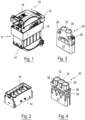
- Fig. 1
- a perspective view of a connector that is fully inserted and latched in a mating connector;
- Fig. 2
- a housing of the connector of
Fig. 1 ; - Fig. 3
- an H-MTD module for two wire pairs;
- Fig. 4
- an H-MTD module for three wire pairs;
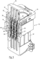
- Fig. 5
- a cross-sectional view through the assembly of
Fig. 1 ; - Fig. 6
- an enlarged partial view of
Fig. 5 ; - Fig. 7
- a perspective view of a cover;
- Fig. 8
- an enlarged detail of the cover of
Fig. 7 ; and - Fig. 9
- a sideview of an H-MTD module.
-
Fig. 1 depicts a perspective view of an assembly comprising aconnector 10 that is fully inserted and latched in amating connector 12. Theconnector 10 comprises ahousing 14 shown inFig. 2 and themating connector 12 comprises a housing 14'. - The
housing 14 of theconnector 10 comprises a plurality ofchambers 16 for respectively receiving a High-Speed Modular Twisted-Pair Data module (H-MTD module) such as shown inFigs. 3, 4 or9 . Each H-MTD module comprises one or more electrical terminals that are fixed in the H-MTD module and connected to a wire. The H-MTD modules are inserted in thechambers 16 of thehousing 14 in an axial direction that is identical to the insertion direction of theconnector 10 into themating connector 12. - After the H-MTD modules are inserted in the
chambers 16 of thehousing 14, acover 18 is snapped onto thehousing 14 thereby closing the housing14 and latching thecover 18 with thehousing 14. -
Fig. 3 and Fig. 4 depict two different embodiments of an H-MTD module. The H-MTD module 20 shown inFig. 3 comprises a cuboidelmain body 21 with receptacles for accommodating electrical terminals and with twoopenings - As shown in
Fig. 3 , the H-MTD module 20 comprises respectively onespring main body 21 adjacent theopenings - In the embodiment of
Fig. 3 thespring 26 is integrally formed with themain body 21 of the H-MTD module 20 and has the form of an arc-shaped web that spans an aperture formed in the H-MTD module 20. Thefurther spring 28 of the H-MTD module 20 has a Y-shaped cross-section wherein two limbs of the Y are facing upwards and a third limb of the Y is integrally connected to themain body 21. - An alternative embodiment of an H-
MTD module 30 with a cuboidelmain body 31 is shown inFig. 4 . This embodiment is similar to the embodiment ofFig. 3 but comprises threeopenings main body 31. The H-MTD module 30 also comprises at an upper side of themain body 31 respectively onespring 38 adjacent bothouter openings springs 38 have a design that is similar to thespring 26 of the H-MTD module 20 ofFig. 3 . Thesprings 38 are also integrally formed with the H-MTD module 30 and have the form of an arc-shaped web spanning an aperture 39. -
Fig. 5 shows a perspective cross-sectional view of the assembly ofFig. 1 . Theconnector 10 is fully inserted into themating connector 12 and latched by means of atraversable lever 15. For illustrative purposes, only one H-MTD module 30 is shown that is inserted in achamber 16 of thehousing 14 with respectively one wire pair being inserted in eachopening electrical terminal 40 that is fixed in the H-MTD module 30. - As shown in
Fig. 5 , themating connector 12 comprises an H-MTD mating module 30' that has a similar design like the H-MTD module 30 and accommodates mating electrical contacts 40'. -
Fig. 6 depicts an enlarged partial view ofFig. 5 to illustrate that the H-MTD module 30 is fixed in thehousing 14 by means ofhooks housing 14. However, in order to bias the H-MTD module 30 in the axial direction towards themating connector 12, thecover 18 contacts bothsprings 38 of the H-MTD module 30 such that thesprings 38 are compressed and bias the H-MTD module 30 away from thecover 18 and towards themating connector 12. - According to a further embodiment shown in
Figs. 7 and 8 the H-MTD modules may be biased by means of a spring provided between thecover 18 and the H-MTD module, wherein the spring is integrally formed with thecover 18. As shown inFig. 7 and in particular in the enlarged detail ofFig. 8 , thecover 18 may be provided with a plurality ofsprings 48 integrally formed with thecover 18 and comprising aweb 50 spanning an approximatelyrectangular opening 52 in the cover. Further, aprotrusion 54 extends into theopening 52 opposite theweb 50 serving as an abutment for thespring 50. - As shown in
Fig. 7 , thesprings 48 are provided at the bottom side of thecover 18 along two parallel lower edges of thecover 18. Thesesprings 48 can be used - alternatively or in addition to springs of the H-MTD module - to bias the H-MTD module in the axial direction. In all embodiments shown in the drawings the springs are provided between thecover 18 and the H-MTD module. - In the embodiments shown, the spring(s) that bias(es) the H-MTD module of the
connector 10 in the axial direction urge(s) the H-MTD module connector 10 away from thecover 18 towards the mating-connector 12 until the H-MTD module 30 contacts at its front end an abutment surface 31' (Fig. 5 ) of the H-MTD mating module 30' to position and fix the H-MTD module connector 10 in a defined position with regard to the mating H-MTD module 30'. -
Fig. 9 shows a sideview of a further embodiment of an H-MTD module 60. In this embodiment the H-MTD module 60 is provided with a biasing element that urges an electrical terminal (not shown) inserted in the H-MTD module 60 in the axial direction against an abutment of the H-MTD module 60. In this embodiment, the biasing element is integrally formed with the H-MTD module 60 and has the shape of an arc-shapedweb 62 spanning anaperture 64. The biasingelement 64 urges the electrical terminal in a fixed position having no play when the electrical terminal is finally mounted in the H-MTD module 60, e.g. by means of a further element assuring the correct position of the terminal (TPA). - A biasing element as described above can be included in all embodiments of an H-MTD module.
Claims (14)
- Connector (10), comprisinga housing (14) with at least one High-Speed Modular Twisted-Pair Data, H-MTD, module (20, 30, 60) inserted in the housing (14) in an axial direction, at least one electrical terminal (40) fixed in the H-MTD module (20, 30, 60), a cover (18) latched with the housing (14), andat least one spring (26, 28, 38, 48) that biases the H-MTD module (20, 30, 60) in the axial direction.
- Connector according to claim 1, wherein the at least one spring (26, 28, 38, 48) is provided between the cover (18) and the H-MTD module (20, 30, 60).
- Connector according to claim 1 or 2, wherein the at least one spring (26, 28, 38, 48) is integrally formed with the H-MTD module (20, 30, 60) and/or with the cover (18).
- Connector according to any one of the preceding claims, wherein the at least one spring (26, 38) is formed as an arc-shaped web.
- Connector according to any one of the preceding claims 1 to 3, wherein the at least one spring (28) has a Y-shaped cross-section.
- Connector according to any one of the preceding claims 1 to 4, wherein the at least one spring (26, 38, 48) is formed by a web spanning an aperture (39, 52).
- Connector according to any one of the preceding claims, wherein the at least one spring (26, 28, 38, 48) urges the H-MTD module (20, 30, 60) away from the cover (18).
- Connector according to any one of the preceding claims 1 to 6, wherein the at least one spring urges the H-MTD module (20, 30, 60) towards the cover (18).
- Connector according to any one of the preceding claims 1, 2 or 4 to 8, wherein the at least one spring is a separate part.
- Connector according to any one of the preceding claims, wherein the H-MTD module (60) has biasing element (64) that urges the electrical terminal (40) in the axial direction against an abutment of the H-MTD module (60).
- An assembly of a connector (10) according to any one of the preceding claims that is fully inserted and latched in a mating connector (12), wherein the at least one spring (26, 28, 38, 48) urges the H-MTD module (20, 30, 60) in the axial direction against an abutment (31') of the mating connector (12).
- An assembly according to claim 11, wherein an H-MTD mating module (30') is inserted in a housing (14') of the mating connector (12) and at least one electrical terminal (40') is fixed in the H-MTD mating module (30'), wherein the abutment (31') of the mating connector (12) is provided on the H-MTD mating module (30') of the mating connector (12).
- A cable harness comprising at least one connector (10) according to any one of the preceding claims 1 to 10.
- A cable harness comprising at least one assembly according to any one of the preceding claims 11 or 12.
Priority Applications (3)
| Application Number | Priority Date | Filing Date | Title |
|---|---|---|---|
| EP22212939.7A EP4386998A1 (en) | 2022-12-12 | 2022-12-12 | Connector |
| US18/536,640 US20240195114A1 (en) | 2022-12-12 | 2023-12-12 | Electrical connector |
| CN202311700073.7A CN118198802A (en) | 2022-12-12 | 2023-12-12 | Connector |
Applications Claiming Priority (1)
| Application Number | Priority Date | Filing Date | Title |
|---|---|---|---|
| EP22212939.7A EP4386998A1 (en) | 2022-12-12 | 2022-12-12 | Connector |
Publications (1)
| Publication Number | Publication Date |
|---|---|
| EP4386998A1 true EP4386998A1 (en) | 2024-06-19 |
Family
ID=84488265
Family Applications (1)
| Application Number | Title | Priority Date | Filing Date |
|---|---|---|---|
| EP22212939.7A Pending EP4386998A1 (en) | 2022-12-12 | 2022-12-12 | Connector |
Country Status (3)
| Country | Link |
|---|---|
| US (1) | US20240195114A1 (en) |
| EP (1) | EP4386998A1 (en) |
| CN (1) | CN118198802A (en) |
Citations (3)
| Publication number | Priority date | Publication date | Assignee | Title |
|---|---|---|---|---|
| US5547394A (en) * | 1995-03-08 | 1996-08-20 | Molex Incorporated | Panel mounted electrical connector |
| CN101783460A (en) * | 2010-03-01 | 2010-07-21 | 李立国 | Vibration isolation device of blind-mate connector of power battery box of electric vehicle |
| DE202019106237U1 (en) * | 2019-11-08 | 2020-12-04 | Ingun Prüfmittelbau Gmbh | High frequency test pin device |
Family Cites Families (29)
| Publication number | Priority date | Publication date | Assignee | Title |
|---|---|---|---|---|
| US4090764A (en) * | 1973-12-19 | 1978-05-23 | The Deutsch Company Electronic Components Division | Modular electrical connector |
| US4032209A (en) * | 1976-01-15 | 1977-06-28 | Appleton Electric Company | Multiple socket assembly for electrical components |
| GB2292642B (en) * | 1994-08-22 | 1998-06-03 | Sumitomo Wiring Systems | Connector |
| US5643014A (en) * | 1995-05-17 | 1997-07-01 | Lucent Technologies Inc. | Mounting of protectors in connector blocks |
| US6027360A (en) * | 1998-06-10 | 2000-02-22 | Yazaki Corporation | Junction block bracket for floating connector attachment |
| US6095852A (en) * | 1998-12-17 | 2000-08-01 | Yazaki North America, Inc. | Connector bracket wire shield with connector retention arms |
| JP2001314015A (en) * | 2000-04-27 | 2001-11-09 | Sumitomo Wiring Syst Ltd | Electric junction box with tentative retainer of connector |
| ATE393464T1 (en) * | 2002-02-14 | 2008-05-15 | Mta Spa | MODULAR FUSE HOLDING STRUCTURE AND MODULAR FUSE HOLDER |
| JP2005322609A (en) * | 2004-04-07 | 2005-11-17 | Jst Mfg Co Ltd | Electrical connection device |
| US7241183B2 (en) * | 2005-01-31 | 2007-07-10 | Delphi Technologies, Inc. | Electrical connector with integrated terminal position assurance and wire cover |
| US7182626B2 (en) * | 2005-04-11 | 2007-02-27 | Molex Incorporated | Electrical connector with improved latch means |
| JP4550671B2 (en) * | 2005-06-09 | 2010-09-22 | タイコエレクトロニクスジャパン合同会社 | Lever type connector |
| US7594821B1 (en) * | 2008-09-17 | 2009-09-29 | Yazaki North America, Inc. | Sealing gap formed by assembled connector parts |
| US7611365B1 (en) * | 2009-01-13 | 2009-11-03 | Yazaki North America, Inc. | Connector |
| WO2013146855A1 (en) * | 2012-03-30 | 2013-10-03 | 古河電気工業株式会社 | Electric component connection unit and junction box |
| WO2014113933A1 (en) * | 2013-01-23 | 2014-07-31 | 华为技术有限公司 | Blind-mate integrated connector |
| CN104167628A (en) * | 2013-05-16 | 2014-11-26 | 鸿富锦精密工业(深圳)有限公司 | Connector combination unit |
| DE202015009386U1 (en) * | 2015-09-04 | 2017-05-24 | Amphenol-Tuchel Electronics Gmbh | System of connector module frames and adapter elements as well as modular connectors with such a system |
| US9911565B2 (en) * | 2015-10-01 | 2018-03-06 | Littelfuse, Inc. | Sealed modular power distribution apparatus |
| EP3400631B1 (en) * | 2016-06-23 | 2019-05-15 | Harting Electric GmbH & Co. KG | Holding frame for a plug connector and mounting method |
| DE102016213251A1 (en) * | 2016-07-20 | 2018-01-25 | Harting Electric Gmbh & Co. Kg | Holding frame arrangement with base frame and fixing element and assembly process |
| DE102017108433B4 (en) * | 2017-04-20 | 2021-09-30 | Harting Electric Gmbh & Co. Kg | Holding frame for a connector and assembly method |
| DE102017108430B4 (en) * | 2017-04-20 | 2021-09-30 | Harting Electric Gmbh & Co. Kg | Holding frame for a heavy connector and system |
| JP6564815B2 (en) * | 2017-06-26 | 2019-08-21 | 矢崎総業株式会社 | connector |
| DE102017124632A1 (en) * | 2017-10-23 | 2019-04-25 | Harting Electric Gmbh & Co. Kg | Holding frame for an industrial connector |
| DE102018106880A1 (en) * | 2018-03-22 | 2019-09-26 | Harting Electric Gmbh & Co. Kg | Modular contact carrier for an industrial connector |
| DE102018115371A1 (en) * | 2018-06-26 | 2020-01-02 | Harting Electric Gmbh & Co. Kg | Connector module for an industrial connector |
| US10855024B2 (en) * | 2018-10-29 | 2020-12-01 | Te Connectivity Corporation | Electrical connector with latches and terminal position assurance projections provided on hinged cover |
| JP7393105B2 (en) * | 2021-03-19 | 2023-12-06 | トヨタ自動車株式会社 | Connector connection method and connector set |
-
2022
- 2022-12-12 EP EP22212939.7A patent/EP4386998A1/en active Pending
-
2023
- 2023-12-12 CN CN202311700073.7A patent/CN118198802A/en active Pending
- 2023-12-12 US US18/536,640 patent/US20240195114A1/en active Pending
Patent Citations (3)
| Publication number | Priority date | Publication date | Assignee | Title |
|---|---|---|---|---|
| US5547394A (en) * | 1995-03-08 | 1996-08-20 | Molex Incorporated | Panel mounted electrical connector |
| CN101783460A (en) * | 2010-03-01 | 2010-07-21 | 李立国 | Vibration isolation device of blind-mate connector of power battery box of electric vehicle |
| DE202019106237U1 (en) * | 2019-11-08 | 2020-12-04 | Ingun Prüfmittelbau Gmbh | High frequency test pin device |
Also Published As
| Publication number | Publication date |
|---|---|
| CN118198802A (en) | 2024-06-14 |
| US20240195114A1 (en) | 2024-06-13 |
Similar Documents
| Publication | Publication Date | Title |
|---|---|---|
| WO2022083683A1 (en) | Integrally shielded cable connector | |
| US4426127A (en) | Coaxial connector assembly | |
| CN101828308B (en) | Electrical Connector Assembly | |
| US8298015B2 (en) | Electrical connector assembly with improved shield and shield coupling | |
| EP0446980B2 (en) | Connector assembly for printed circuit boards | |
| EP0570181B1 (en) | High frequency electrical connector | |
| US7985100B2 (en) | Computer network connector | |
| CN103124030B (en) | Electrical connector with interface grounding feature | |
| EP0738029A1 (en) | Lockable electrical connector | |
| US20040097134A1 (en) | Shielded electrical connector | |
| CA2240236C (en) | Coaxial connector | |
| US20090068860A1 (en) | Connector device | |
| JP4318810B2 (en) | Modular connector configured to be used with different contact devices with reduced crosstalk | |
| US6290524B1 (en) | System for varying capacitive coupling between electrical terminals | |
| WO2017218771A1 (en) | Overmolded lead frame providing contact support and impedance matching properties | |
| EP0590544A1 (en) | Shielded electrical connector assembly | |
| US11600957B2 (en) | Selectively plated plastic part | |
| US10594085B2 (en) | Electrical connector and electrical contact configured to reduce resonance | |
| US20240195114A1 (en) | Electrical connector | |
| US6942525B2 (en) | Plug | |
| US10326244B2 (en) | Electrical connector and electrical contact configured to reduce resonance | |
| US7011545B2 (en) | Socket connector for receiving a plurality of termination sockets for coaxial cables | |
| US7273393B2 (en) | Connector shell for a multiple wire cable assembly | |
| US20250385474A1 (en) | Electrical System with a Connector Having a Shorting Spring | |
| WO2025068874A1 (en) | Connector flex shield with crimped portion |
Legal Events
| Date | Code | Title | Description |
|---|---|---|---|
| PUAI | Public reference made under article 153(3) epc to a published international application that has entered the european phase |
Free format text: ORIGINAL CODE: 0009012 |
|
| STAA | Information on the status of an ep patent application or granted ep patent |
Free format text: STATUS: THE APPLICATION HAS BEEN PUBLISHED |
|
| AK | Designated contracting states |
Kind code of ref document: A1 Designated state(s): AL AT BE BG CH CY CZ DE DK EE ES FI FR GB GR HR HU IE IS IT LI LT LU LV MC ME MK MT NL NO PL PT RO RS SE SI SK SM TR |
|
| STAA | Information on the status of an ep patent application or granted ep patent |
Free format text: STATUS: REQUEST FOR EXAMINATION WAS MADE |
|
| 17P | Request for examination filed |
Effective date: 20240717 |
|
| RBV | Designated contracting states (corrected) |
Designated state(s): AL AT BE BG CH CY CZ DE DK EE ES FI FR GB GR HR HU IE IS IT LI LT LU LV MC ME MK MT NL NO PL PT RO RS SE SI SK SM TR |
|
| RAP3 | Party data changed (applicant data changed or rights of an application transferred) |
Owner name: APTIV TECHNOLOGIES AG |
|
| STAA | Information on the status of an ep patent application or granted ep patent |
Free format text: STATUS: EXAMINATION IS IN PROGRESS |
|
| 17Q | First examination report despatched |
Effective date: 20251212 |