EP4386980A1 - Antenna assembly for a wireless ear computer - Google Patents
Antenna assembly for a wireless ear computer Download PDFInfo
- Publication number
- EP4386980A1 EP4386980A1 EP23216386.5A EP23216386A EP4386980A1 EP 4386980 A1 EP4386980 A1 EP 4386980A1 EP 23216386 A EP23216386 A EP 23216386A EP 4386980 A1 EP4386980 A1 EP 4386980A1
- Authority
- EP
- European Patent Office
- Prior art keywords
- antenna
- computer
- ground
- flexible circuit
- wireless ear
- Prior art date
- Legal status (The legal status is an assumption and is not a legal conclusion. Google has not performed a legal analysis and makes no representation as to the accuracy of the status listed.)
- Pending
Links
Images



Classifications
-
- H—ELECTRICITY
- H01—ELECTRIC ELEMENTS
- H01Q—ANTENNAS, i.e. RADIO AERIALS
- H01Q1/00—Details of, or arrangements associated with, antennas
- H01Q1/27—Adaptation for use in or on movable bodies
- H01Q1/273—Adaptation for carrying or wearing by persons or animals
-
- H—ELECTRICITY
- H04—ELECTRIC COMMUNICATION TECHNIQUE
- H04R—LOUDSPEAKERS, MICROPHONES, GRAMOPHONE PICK-UPS OR LIKE ACOUSTIC ELECTROMECHANICAL TRANSDUCERS; ELECTRIC HEARING AIDS; PUBLIC ADDRESS SYSTEMS
- H04R1/00—Details of transducers, loudspeakers or microphones
- H04R1/10—Earpieces; Attachments therefor ; Earphones; Monophonic headphones
- H04R1/1016—Earpieces of the intra-aural type
-
- H—ELECTRICITY
- H01—ELECTRIC ELEMENTS
- H01Q—ANTENNAS, i.e. RADIO AERIALS
- H01Q1/00—Details of, or arrangements associated with, antennas
- H01Q1/12—Supports; Mounting means
- H01Q1/22—Supports; Mounting means by structural association with other equipment or articles
- H01Q1/24—Supports; Mounting means by structural association with other equipment or articles with receiving set
- H01Q1/241—Supports; Mounting means by structural association with other equipment or articles with receiving set used in mobile communications, e.g. GSM
- H01Q1/242—Supports; Mounting means by structural association with other equipment or articles with receiving set used in mobile communications, e.g. GSM specially adapted for hand-held use
-
- H—ELECTRICITY
- H01—ELECTRIC ELEMENTS
- H01Q—ANTENNAS, i.e. RADIO AERIALS
- H01Q1/00—Details of, or arrangements associated with, antennas
- H01Q1/36—Structural form of radiating elements, e.g. cone, spiral, umbrella; Particular materials used therewith
-
- H—ELECTRICITY
- H01—ELECTRIC ELEMENTS
- H01Q—ANTENNAS, i.e. RADIO AERIALS
- H01Q1/00—Details of, or arrangements associated with, antennas
- H01Q1/48—Earthing means; Earth screens; Counterpoises
-
- H—ELECTRICITY
- H01—ELECTRIC ELEMENTS
- H01Q—ANTENNAS, i.e. RADIO AERIALS
- H01Q1/00—Details of, or arrangements associated with, antennas
- H01Q1/50—Structural association of antennas with earthing switches, lead-in devices or lightning protectors
-
- H—ELECTRICITY
- H01—ELECTRIC ELEMENTS
- H01Q—ANTENNAS, i.e. RADIO AERIALS
- H01Q9/00—Electrically-short antennas having dimensions not more than twice the operating wavelength and consisting of conductive active radiating elements
- H01Q9/04—Resonant antennas
- H01Q9/30—Resonant antennas with feed to end of elongated active element, e.g. unipole
- H01Q9/42—Resonant antennas with feed to end of elongated active element, e.g. unipole with folded element, the folded parts being spaced apart a small fraction of the operating wavelength
-
- H—ELECTRICITY
- H04—ELECTRIC COMMUNICATION TECHNIQUE
- H04R—LOUDSPEAKERS, MICROPHONES, GRAMOPHONE PICK-UPS OR LIKE ACOUSTIC ELECTROMECHANICAL TRANSDUCERS; ELECTRIC HEARING AIDS; PUBLIC ADDRESS SYSTEMS
- H04R1/00—Details of transducers, loudspeakers or microphones
- H04R1/10—Earpieces; Attachments therefor ; Earphones; Monophonic headphones
- H04R1/1025—Accumulators specially adapted for earpieces; Arrangements specially adapted for charging thereof
-
- H—ELECTRICITY
- H04—ELECTRIC COMMUNICATION TECHNIQUE
- H04R—LOUDSPEAKERS, MICROPHONES, GRAMOPHONE PICK-UPS OR LIKE ACOUSTIC ELECTROMECHANICAL TRANSDUCERS; ELECTRIC HEARING AIDS; PUBLIC ADDRESS SYSTEMS
- H04R1/00—Details of transducers, loudspeakers or microphones
- H04R1/10—Earpieces; Attachments therefor ; Earphones; Monophonic headphones
- H04R1/1091—Details not provided for in groups H04R1/1008 - H04R1/1083
-
- H—ELECTRICITY
- H04—ELECTRIC COMMUNICATION TECHNIQUE
- H04R—LOUDSPEAKERS, MICROPHONES, GRAMOPHONE PICK-UPS OR LIKE ACOUSTIC ELECTROMECHANICAL TRANSDUCERS; ELECTRIC HEARING AIDS; PUBLIC ADDRESS SYSTEMS
- H04R2420/00—Details of connection covered by H04R, not provided for in its groups
- H04R2420/07—Applications of wireless loudspeakers or wireless microphones
Definitions
- the subject matter herein relates generally to wireless ear computers.
- the wearable device typically includes many electrical components, such as a battery, a microphone, a speaker, a touch of motion sensors, a circuit board assembly, and other components densely integrated into the housing of the wearable device.
- the dense integration of the electrically conductive components into the compact space allows the limited space for an antenna to radiate effectively.
- a wireless ear computer in one embodiment, includes a casing forming a cavity.
- the wireless ear computer includes a flexible circuit received in the cavity.
- the flexible circuit surrounds a component pocket configured to receive at least one electrical component.
- the flexible circuit has a power circuit (battery circuit) and a speaker circuit.
- the flexible circuit includes a ground plane.
- the wireless ear computer includes a battery received in the component pocket.
- the battery is operably coupled to the power circuit to power the at least one electrical component.
- the battery is connected to the ground plane of the flexible circuit.
- the wireless ear computer includes a speaker operably coupled to the speaker circuit to control the speaker.
- the speaker is connected to the ground plane of the flexible circuit.
- the wireless ear computer includes an antenna having an antenna element extending along the casing.
- the antenna element is spaced apart from, and located outward of, the flexible circuit.
- the antenna includes an antenna feed and an antenna ground.
- the antenna ground is connected to the ground plane of the flexible circuit.
- the antenna may include an inner portion extending along the interior surface of the casing, an outer portion extending along the exterior surface of the casing, and a connecting portion between the inner portion and the outer portion, the inner portion of the antenna including the antenna feed connected to a transmission line and the antenna ground connected to the ground plane.
- the connecting portion may include at least one of a side trace wrapping around the side of the casing from the interior surface to the exterior surface and a through trace extending through the casing between the interior surface and the exterior surface.
- the flexible circuit may include panels on differing sides of the component pocket to one another, and the panels may be continuous with one another, for example manufactured from a single substrate.
- the ground plane of the flexible circuit may be directly between the antenna and the at least one electrical component in the component pocket to avoid interference.
- a wireless ear computer in another embodiment, includes a casing forming a cavity.
- the casing includes an interior surface and an exterior surface.
- the wireless ear computer includes a flexible circuit received in the cavity.
- the flexible circuit surrounds a component pocket configured to receive at least one electrical component.
- the flexible circuit has a power circuit (battery circuit) and a speaker circuit.
- the flexible circuit includes a ground plane.
- the wireless ear computer includes a battery received in the component pocket.
- the battery is operably coupled to the power circuit to power the at least one electrical component.
- the battery is connected to the ground plane of the flexible circuit.
- the wireless ear computer includes a speaker operably coupled to the speaker circuit to control the speaker.
- the speaker is connected to the ground plane of the flexible circuit.
- the wireless ear computer includes an antenna extending along the casing.
- the antenna element is spaced apart from, and located outward of, the flexible circuit.
- the antenna includes an inner portion extending along the interior surface of the casing.
- the antenna includes an outer portion extending along the exterior surface of the casing.
- the antenna includes a connecting portion between the inner portion and the outer portion.
- the inner portion of the antenna includes an antenna feed connected to a transmission line.
- the inner portion of the antenna includes an antenna ground connected to the ground plane of the flexible circuit.
- a wireless ear computer in a further embodiment, includes a casing forming a cavity.
- the casing includes an interior surface and an exterior surface.
- the wireless ear computer includes a flexible circuit received in the cavity.
- the flexible circuit surrounds a component pocket configured to receive at least one electrical component.
- the flexible circuit has a power circuit (battery circuit) and a speaker circuit.
- the flexible circuit includes a transceiver.
- the flexible circuit includes a ground plane.
- the wireless ear computer includes a battery received in the component pocket. The battery is operably coupled to the power circuit to power the at least one electrical component. The battery is connected to the ground plane of the flexible circuit.
- the wireless ear computer includes a speaker operably coupled to the speaker circuit to control the speaker. The speaker is connected to the ground plane of the flexible circuit.
- the wireless ear computer includes an RF front-end module coupled to the flexible circuit.
- the RF front-end module is operably coupled to the transceiver.
- the wireless ear computer includes an antenna having an antenna element extending along the casing. The antenna element is spaced apart from, and located outward of, the flexible circuit.
- the antenna includes an antenna feed and an antenna ground. The antenna feed is connected to the RF front-end module.
- the antenna ground is connected to the ground plane of the flexible circuit.
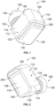
- FIG 1 is a front perspective view of the wireless ear computer 100 in accordance with an exemplary embodiment.
- Figure 2 is a rear perspective view of the wireless ear computer 100 in accordance with an exemplary embodiment.
- the wireless ear computer 100 is a wearable device configured be worn in the ear of a user.
- the wireless ear computer 100 is a wireless earphone in various embodiments.
- the wireless ear computer 100 includes an antenna 200 providing wireless communication, such as with a portable device, such as a smart phone or other handheld device.
- the antenna 200 provides stable wireless connection with the portable device.
- the antenna design takes into consideration the complex device structure of the wireless ear computer 100, the small size constraints of the wireless ear computer 100, and the close human ear condition of the wireless ear computer 100 to provide good antenna performance for wireless connection with the portable device.
- the wireless ear computer 100 includes a casing 110 forming a cavity 112 holding the internal electronics of the wireless ear computer 100.
- the casing 110 includes a main body 114 forming the cavity 112 and at least one cover 116 to close the cavity 112.
- the antenna 200 may be provided on the main body 114 and/or the cover 116.
- the casing 110 extends between a top 120 and a bottom 122.
- the casing 110 extends between an inner end 124 and an outer end 126.
- the cover 116 may be provided at the outer end 126.
- a plug portion 128 is provided at the inner end 124 and is configured to be plugged into the ear of the user. Rubber tips may be provided on the plug portion 128 to plug into the ear of the user.
- the casing 110 extends between a front 136 and a rear 138.
- the casing 110 may be a multi-piece casing, such as a clamshell type casing. The pieces may be secured together using fasteners. Other types of securing features may be used in alternative embodiments, such as clips, latches, adhesive, or other securing features.
- the casing 110 is shown as generally box shaped having the plug portion 128 extending therefrom, such as at a downward and inward angle, it is realized that the casing 110 may have other shapes in alternative embodiments.
- the casing 110 may be contoured to fit within the user's ear.
- the internal electronic components of the wireless ear computer 100 are designed to fit within the cavity 112 of the casing 110 and extend into the plug portion 128 to deliver sound to the user's ear.
- the antenna 200 is integrated with the internal electronics of the wireless ear computer 100 and is patterned and positioned to provide robust performance. In the illustrated embodiment, the antenna 200 extends along the outer end 126 of the casing 110, such as to locate the antenna 200 furthest from the user's ear.
- the shape of the pattern of the antenna 200 is located based on the positioning of the internal electronics to provide robust performance.
- Figure 3 is a perspective view of the internal electronic components 102 of the wireless ear computer 100 in accordance with an exemplary embodiment.
- Figure 4 is an end view of the internal electronic components 102 of the wireless ear computer 100 in accordance with an exemplary embodiment.
- Figure 5 is a side view of the internal electronic components 102 of the wireless ear computer 100 in accordance with an exemplary embodiment.
- the casing 110 ( Figures 1-2 ) is removed to illustrate the internal electronic components 102.
- the internal electronic components 102 are configured to be tightly packaged within the casing 110.
- the internal electronic components 102 include a battery 104 and a speaker 106.
- Other types of internal electronic components 102 may additionally be included, such as a microphone, sensors (for example, touch sensors, motion sensors, and the like), indicators, or other types of electronic components.
- the wireless ear computer 100 includes a control module 150 for controlling operation of the electronic components 102.
- the control module 150 includes a flexible circuit 152 having various circuit components 154 for controlling the wireless ear computer 100.
- the battery 104 is connected to the flexible circuit 152, such as to a power circuit (battery circuit) that provides power to other components from the battery 104.
- the speaker 106 is connected to the flexible circuit 152, such as to a speaker circuit that controls operation of the speaker 106.
- the antenna 200 ( Figure 5 ) is connected to the control module 150.
- the antenna 200 may be connected to a transceiver 156 of the circuit components 154.
- the antenna 200 may be connected to an RF front-end module 158 of the circuit components 154.
- the flexible circuit 152 includes a ground plane 160.
- the antenna 200 may be electrically connected to the ground plane 160.
- the electronic components 102 may be electrically connected to the ground plane 160.
- the circuit components 154 may be electrically connected to the ground plane 160. Electrically connecting the various components to the ground plane 160 may enhance the performance of the antenna 200, such as providing a common or ground for all of the electrically conductive components of the wireless ear computer 100.
- the flexible circuit 152 surrounds a component pocket 162.
- the flexible circuit 152 may extend along the multiple sides of the component pocket 162 to connect the various components located at various positions within the casing 110.
- the flexible circuit 152 includes various panels 164 defining distinct portions of the flexible circuit 152.
- the panels 164 may be electrically connected by traces, contacts, or other connecting structures 166.
- One or more of the panels 164 may be continuous with each other.
- the flexible circuit 152 includes an inner portion 152a, an outer portion 152b, an upper portion 152c, a lower portion 152d, and a front portion 152e.
- the flexible circuit 152 may include greater or fewer portions in alternative embodiments, such as a rear portion (not shown).
- the panels 164 and the connecting structures 166 are manufactured from a single substrate, such as a flexible printed circuit board having various circuits formed on the panels 164 and the connecting structures 166.
- various components are located within the component pocket 162.
- the battery 104 may be located within the component pocket 162.
- the RF front-end module 158 and/or the transceiver 156 may be located within the component pocket 162.
- the ground plane 160 of the flexible circuit 152 may surround the components of the wireless ear computer 100.
- the flexible circuit 152 is fitted to the casing 110, such as to extend along the interior surface of the casing 110 to define as large of a component pocket 162 as practical.
- other components may be located between the flexible circuit 152 and the inner surface of the casing 110.
- Figure 6 is a schematic view of a side (for example, front side) of the wireless ear computer 100 in accordance with an exemplary embodiment.
- Figure 7 is a schematic view of an end (for example, top end) of the wireless ear computer 100 in accordance with an exemplary embodiment.
- Figures 6 and 7 show the internal electronic components 102 and the antenna 200 in accordance with an exemplary embodiment.
- the flexible circuit 152 surrounds the component pocket 162.
- the components are located within the component pocket 162.
- the battery 104 is located within the component pocket 162. Terminals of the battery 104 may be electrically connected to the flexible circuit 152.
- Other components may additionally be located within the component pocket 162.
- the antenna 200 is connected to the flexible circuit 152.
- the antenna 200 may be electrically connected to the ground plane of the flexible circuit 152.
- the antenna 200 includes an antenna feed 202 and an antenna ground 204 connected to an antenna element 210 configured to receive and/or transmit signals.
- a transmission line 168 is connected to the antenna feed 202 of the antenna 200.
- the antenna 200 is an inverted F antenna (IFA).
- the IFA includes a monopole antenna, defined by the antenna element 210, running parallel to the ground plane 160 and grounded at one end by the antenna ground 204.
- the ground plane 160 may be a layer of the flexible circuit 152, such as an outer layer or an inner layer.
- the antenna element 210 is fed by the antenna feed 202 at an intermediate point a distance from the antenna ground 204.
- the antenna 200 is short and compact allowing the antenna 200 to be contained within the casing 110 of the wireless ear computer 100.
- the antenna 200 is positioned relative to the internal electronic components 102 and is patterned or shaped to provide impedance matching within the antenna circuit.
- the antenna 200 radiates efficiently without the need for extraneous matching components.
- the antenna 200 may be a planar inverted F antenna (PIFA), which may be printed in a microstrip format on the casing 110.
- PIFA planar inverted F antenna
- Figure 8 is a schematic view of an end (for example, top end) of the wireless ear computer 100 in accordance with an exemplary embodiment.
- Figure 9 is a schematic view of a portion of the wireless ear computer 100 in accordance with an exemplary embodiment showing the connection of the antenna 200.
- Figure 8 shows the internal electronic components 102 and the antenna 200 in accordance with an exemplary embodiment.
- the transmission line 168 is connected between the antenna 200 and the RF front-end module 158.
- the transmission line 168 may be a flexible circuit or a coaxial cable extending between the RF front-end module 158 and the antenna 200.
- the antenna feed 202 is connected to a transmission feed of the transmission line 168.
- the antenna ground 204 is connected to a transmission ground of the transmission line 168.
- the transmission feed may be an inner conductor of the coaxial cable and the transmission ground may be an outer conductor of the coaxial cable.
- the transmission feed may be a first trace or pad on the transmission flexible circuit and the transmission ground may be a second trace or pad on the transmission flexible circuit.
- a ground conductor 170 is provided between the antenna ground 204 and the ground plane 160.
- the ground conductor 170 may be a solder connection between the transmission ground and the ground plane 160 and/or the antenna ground 204.
- the ground conductor 170 may be a stamped and formed contact, such as a spring contact, between the transmission ground and the ground plane 160 and/or the antenna ground 204.
- the ground conductor 170 may be a conductive foam that is compressible between the transmission ground and the ground plane 160 and/or the antenna ground 204.
- the ground conductor 170 may be a conductive tape between the transmission ground and the ground plane 160 and/or the antenna ground 204.
- Figure 10 is an outer end view of a portion of the wireless ear computer 100 showing the internal electronic components 102 and the antenna 200 in accordance with an exemplary embodiment.
- Figure 11 is a front view of a portion of the wireless ear computer 100 showing the internal electronic components 102 in the antenna 200 in accordance with an exemplary embodiment.
- the casing 110 ( Figure 1 ) is removed to illustrate the antenna 200 relative to the internal electronic components 102.
- the flexible circuit 152 surrounds the component pocket 162.
- the components are located within the component pocket 162.
- the battery 104, the transceiver 156, and the RF front-end module 158 are located within the component pocket 162.
- the battery 104 may be located between the inner portion 152a and the outer portion 152b of the flexible circuit 152. Terminals of the battery 104 may be electrically connected to the flexible circuit 152.
- the transceiver 156 may be located at the upper portion 152c of the flexible circuit 152.
- the RF front-end module 158 may be located at the inner portion 152a of the flexible circuit 152.
- the transmission line 168 is connected between the RF front-end module 158 and the antenna 200.
- the transmission line 168 is part of the flexible circuit 152.
- the transmission line 168 may be a separate flexible circuit in alternative embodiments.
- the transmission line 168 may include a coaxial cable routed between the RF front-end module 158 and the antenna 200.
- the transmission line 168 may include a stamped and formed contact, such as a spring contact, between the RF front-end module 158 and the antenna 200 in other various embodiments.
- the transmission line 168 may include other types of contacts or conductors in alternative embodiments, such as a spring, conductive foam, conductive gasket, a conductive tape, a conductive polymer contact, wire contact, pin contact, or other type of conductor.
- the transmission line 168 is provided at the front portion 152e of the flexible circuit 152.
- the transmission line 168 extends between the inner end and the outer end to connect the RF front-end module 158 and the antenna 200. Other locations are possible in alternative embodiments
- the antenna 200 includes an antenna feed 202 and an antenna ground 204 connected to an antenna element 210 configured to receive and/or transmit signals.
- the antenna feed 202 is configured to be connected to the transmission line 168.
- the antenna feed 202 includes a feed post 206 electrically connected to the transmission line 168.
- the antenna ground 204 is configured to be electrically connected to the ground plane 160 of the flexible circuit 152.
- the antenna ground 204 includes a ground post 208 electrically connected to the ground plane 160.
- the antenna 200 includes an inner portion 220 configured to be located within the cavity 112 of the casing 110, an outer portion 222 configured to be located outside of the casing 110, and a connecting portion 224 between the inner portion 220 and the outer portion 222.
- the connecting portion 224 may extend through the casing 110 or around an edge surface of the casing 110 to connect the inner portion 220 and the outer portion 222.
- the inner portion 220 is located in close proximity to the flexible circuit 152 to electrically connect to the flexible circuit 152.
- the antenna feed 202 and the antenna ground 204 may be provided along the inner portion 220.
- the outer portion 222 is located remote from the flexible circuit 152.
- the outer portion 222 is spaced apart from the ground plane 160 of the flexible circuit 152 to reduce interference and improve antenna signaling (for example, transmit and receive) of the antenna 200.
- the inner portion 220 extends along an interior surface of the casing 110 and/or the cover 116 and the outer portion 222 extends along an exterior surface of the casing 110 and/or the cover 116.
- a ground conductor 170 is provided between the antenna ground 204 and the ground plane 160.
- the ground conductor 170 may be a solder connection between the ground post 208 and a pad or conductor on the flexible circuit 152 connected to the ground plane 160.
- the ground conductor 170 may be a stamped and formed contact, such as a spring contact, between the flexible circuit 152 and the ground post 208.
- the ground conductor 170 may be a conductive foam that is compressible between the ground post 208 and the flexible circuit 152.
- the ground conductor 170 may be a conductive tape between the ground post 208 and the flexible circuit 152.
- the ground conductor 170 may be a cable shield or outer conductor of a coaxial conductor connected between the antenna ground 204 and the flexible circuit 152 or another component, such as the RF front-end module 158.
- the antenna 200 is an inverted F antenna (IFA).
- the IFA includes a monopole antenna, defined by the antenna element 210, running parallel to the ground plane 160 and grounded at one end by the antenna ground 204.
- the antenna element 210 is fed by the antenna feed 202 at an intermediate point a distance from the antenna ground 204.
- the antenna 200 is short and compact allowing the antenna 200 to be contained within the casing 110 of the wireless ear computer 100.
- the antenna 200 is positioned relative to the internal electronic components 102 and is patterned or shaped to provide impedance matching within the antenna circuit.
- the antenna 200 radiates efficiently without the need for extraneous matching components.
- the antenna 200 may be a planar inverted-F antenna (PIFA), which may be printed in a microstrip format on the casing 110.
- PIFA planar inverted-F antenna
- Figure 12 is a schematic view of the antenna 200 in accordance with an exemplary embodiment.
- Figure 12 shows the antenna feed 202, the antenna ground 204 and the antenna element 210 extending from the antenna feed 202 and the antenna ground 204.
- the antenna feed 202 and the antenna ground 204 are provided at the inner portion 220 of the antenna 200.
- Antenna element 210 is provided at the outer portion 222 of the antenna 200.
- the antenna 200 includes a feed line 230, a main line 232, and a branch line 234.
- the main line 232 extends between the feed line 230 and the branch line 234.
- the feed line 230 connects the antenna feed 202 and the antenna ground 204 to the main line 232.
- the feed line 230 includes a connecting line 231 directly connecting the feed post 206 and the ground post 208.
- the connecting line 231 directly connects the feed post 206 and the ground post 208.
- the main line 232 extends along one side of the antenna 200 (for example, along a front side) while the feed line 230 is provided at a bottom of the antenna 200 and the branch line 234 is provided at the top of the antenna.
- the main line 232 spaces the branch line 234 apart from the feed line 230.
- the branch line 234 extends between a front and a rear of the antenna 200. Other orientations are possible in alternative embodiments.
- the branch line 234 includes a first branch 236, a tail 235 extending from a distal end of the first branch 236, and a second branch 238.
- the tail 235 connects the first branch 236 and the second branch 238.
- the first branch 236 is parallel to the second branch 238.
- a slot 237 is formed between the first and second branches 236, 238.
- the slot 237 has a width between the main line 232 and the tail 235.
- the widths and lengths of the branches 236, 238 control antenna characteristics of the antenna 200, such as operating frequencies of the antenna 200.
- the width and length of the slot 237 controls antenna characteristics of the antenna 200, such as operated frequencies of the antenna 200.
- the branch line 234 may include additional branches in alternative embodiments.
- the branches 236 and/or 238 may follow nonlinear paths in alternative embodiments, such as meandering paths.
- Figure 13 is a schematic view of the antenna 200 in accordance with an exemplary embodiment.
- Figure 13 shows the antenna feed 202, the antenna ground 204 and the antenna element 210 extending from the antenna feed 202 and the antenna ground 204.
- the antenna 200 is similar to the antenna shown in Figure 12 ; however, the antenna 200 is provided without the second branch 238 to provide different antenna characteristics. Rather, the branch line 234 includes the first branch 236 and the tail 235.
- the second branch 238 may be removed to position the antenna 200 further from another structure, such as one of the internal components of the wireless ear computer 100. For example, the second branch 238 may be removed to position the antenna 200 further from the ground plane.
- Figure 14 is a schematic view of the antenna 200 in accordance with an exemplary embodiment.
- Figure 14 shows the antenna feed 202, the antenna ground 204 and the antenna element 210 extending from the antenna feed 202 and the antenna ground 204.
- the antenna 200 is similar to the antenna shown in Figure 12 ; however, the antenna 200 is provided without the second branch 238 and without the tail 235 to provide different antenna characteristics. Rather, the branch line 234 includes the first branch 236.
- Figure 15 is a schematic view of the antenna 200 in accordance with an exemplary embodiment.
- Figure 15 shows the antenna feed 202, the antenna ground 204 and the antenna element 210 extending from the antenna feed 202 and the antenna ground 204.
- the antenna 200 is similar to the antenna shown in Figure 12 ; however, the antenna 200 is provided without the first branch 236 and without the tail 235 to provide different antenna characteristics. Rather, the branch line 234 includes the second branch 238.
- the first branch 236 may be removed to position the antenna 200 further from another structure, such as one of the internal components of the wireless ear computer 100. For example, the first branch 236 may be removed to position the antenna 200 further from the ground plane.
- the antenna 200 is provided directly on surfaces of the cover 116.
- the antenna 200 may be applied directly to the cover 116.
- the antenna 200 is plated or coated on cover 116.
- the antenna 200 may be applied by a laser direct structuring (LDS) process in various embodiments.
- LDS laser direct structuring
- the antenna 200 may be a microstrip applied to the cover 116.
- the antenna 200 or portions of the antenna 200 may be embedded within and/or pass through the cover 116.
- the cover 116 includes an interior surface 140 ( Figure 17 ) and an exterior surface 142 ( Figure 16 ).
- the inner portion 220 of the antenna 200 is provided on the interior surface 140.
- the outer portion 222 of the antenna 200 is provided on the exterior surface 142.
- the connecting portion 224 connects the inner portion 220 and the outer portion 222.
- the connecting portion 224 includes a side trace 226 connecting the inner portion 220 and the outer portion 222.
- the connecting portion 224 extends along an edge 144 of the cover 116, which extends between the interior surface 140 and the exterior surface 142.
- the side trace 226 is routed along surfaces (inner/edge/outer) of the cover 116.
- the connecting portion 224 may additionally, or alternatively, include a through trace (not shown) connecting the inner portion 220 and the outer portion 222.
- the through trace may extend internally through the cover 116.
- the through trace may be a plated or filled via passing through the cover 116.
- the feed line 230 of the antenna 200 extends along the interior surface 140 between the feed post 206 ( Figure 11 ) and the ground post 208 ( Figure 11 ).
- the feed post 206 and the ground post 208 may be defined by post like structures molded or formed into the cover 116. Alternatively, the feed post 206 and/or the ground post 208 may be defined by a contact or wire coupled to the feed line 230.
- the feed line 230 is located proximate to the bottom of the cover 116.
- the main line 232 extends along the exterior surface 142, such as along a side 146 of the cover 116.
- the branch line 234 extends along the exterior surface 142 from the main line 232.
- the branch line 234 may extend from the side 146 two and opposite sides 148 of the cover 116.
- a large portion of the cover 116 is devoid of the antenna structure. Rather, the pattern of the antenna 200 is designed to extend along certain areas of the cover 116 and avoid other areas of the cover 116, such as to avoid interference by the internal electronic components 102 within the interior of the wireless ear computer 100.
- Figure 18 is an enlarged view of a portion of the wireless ear computer 100 showing the antenna 200 in accordance with an exemplary embodiment.
- the inner portion 220 of the antenna 200 extends into the interior of the casing 110 (shown in Figures 16 and 17 ) while the outer portion 222 of the antenna 200 extends along the exterior of the casing 110.
- the connecting portion 224 extends between the inner portion 220 and the outer portion 222.
- the feed post 206 of the antenna feed 202 is connected to the transmission line 168.
- the ground post 208 of the antenna ground 204 is connected to the ground conductor 170.
- the connecting line 231 of the feed line 230 directly connects the ground post 208 and the feed post 206.
- a through trace 228 of the connecting portion 224 extends from the connecting line 231 to the main line 232.
- the main line 232 is connected to the antenna feed 202 and the antenna ground 204 by the feed line 230 and the through trace 228.
- the through trace 228 connects the inner portion 220 and the outer portion 222.
- the through trace 228 may extend internally through the cover 116.
- the through trace 228 may be a plated or filled via passing through the cover 116.
- the through trace 228 may be connected to the connecting line 231 approximately centered between the feed post 206 and the ground post 208.
- the location of the connection along the connecting line 231 may control the antenna characteristics of the antenna 200. For example, connecting closer to the feed post 206 versus closer to the ground post 208 may affect the operating frequency of the antenna 200.
- the feed post 206 at the antenna feed 202 may be connected to the ground post 208 of the antenna ground 204 by the connecting line 231.
- the connecting line 231 may be connected to the main line 232 by the through trace 228 of the connecting portion 224.
- Figure 19 is an enlarged view of a portion of the wireless ear computer 100 showing the antenna 200 in accordance with an exemplary embodiment.
- the antenna 200 shown in Figure 19 is similar to the antenna shown in Figure 18 ; however, the connecting portion 224 includes the through trace 228 in addition to the side trace 226.
- the through trace 228 extends between the inner portion 220 and the outer portion 222 through an opening or via 180 of the casing.
- the through trace 228 and the side trace 226 are electrically connected to the connecting line 231 of the inner portion 220, and they may both connect the connecting line 231 to the main line 232.
- the through trace 228 may be connected to the connecting line 231 approximately centered between the feed post 206 and the ground post 208.
- the location of the connection along the connecting line 231 may control the antenna characteristics of the antenna 200. For example, connecting closer to the feed post 206 versus closer to the ground post 208 may affect the operating frequency of the antenna 200.
- the side trace 226 may be connected to the connecting line 231 at an end of the connecting line 231.
- the feed post 206 at the antenna feed 202 may be connected to the outer portion 222 by the side trace 226 of the connecting portion 224.
- the ground post 208 of the ground feed 202 may be connected to the outer portion 222 by the through trace 228 of the connecting portion 224.
- Figure 20 is an outer end view of a portion of the wireless ear computer 100 showing the antenna 200 in accordance with an exemplary embodiment.
- Figure 21 is an inner end view of a portion of the wireless ear computer 100 showing the antenna 200 in accordance with an exemplary embodiment.
- the antenna 200 is shown electrically connected to the transmission line 168.
- the transmission line 168 is a flexible circuit.
- the transmission line 168 may be routed from one portion or area of the wireless ear computer 100 to the termination area of the antenna 200.
- the transmission line 168 is electrically connected to the RF front-end module 158 and routed to the antenna termination area.
- the antenna feed 202 is electrically connected to a feed circuit of the transmission line 168.
- the antenna ground 204 may be electrically connected to a ground circuit of the transmission line 168.
- the ground conductor 170 is provided between the transmission line 168 and the ground plane 160.
- the ground conductor 170 may be electrically connected to a ground circuit of the transmission line 168.
- the ground conductor 170 may be electrically connected to the RF front-end module 158 by the transmission line 168.
- the ground conductor 170 is a stamped and formed contact, such as a spring contact, between the transmission line 168 and the ground plane 160 of the flexible circuit 152.
- the ground conductor 170 may additionally be electrically connected to the antenna ground 204 of the antenna 200.
- the ground conductor 170 may be a flexible circuit.
- the ground conductor 170 may be a conductive foam or a conductive tape.
Landscapes
- Engineering & Computer Science (AREA)
- Physics & Mathematics (AREA)
- Acoustics & Sound (AREA)
- Signal Processing (AREA)
- Computer Networks & Wireless Communication (AREA)
- Support Of Aerials (AREA)
- Structure Of Receivers (AREA)
- Telephone Set Structure (AREA)
- Transceivers (AREA)
Abstract
Description
- This application claims benefit to
U.S. Provisional Application No. 63/433,393, filed 16-December-2022 - The subject matter herein relates generally to wireless ear computers.
- There is an increasing trend for wearable devices, such as wireless headphones, which can be linked to the portable device, such as a smart phone. However, some wearable devices, such as wireless headphones, have a small form factor. Design of the antenna structures for feeding the wireless connection between the wearable device and the portable device can be problematic. For example, the wearable device typically includes many electrical components, such as a battery, a microphone, a speaker, a touch of motion sensors, a circuit board assembly, and other components densely integrated into the housing of the wearable device. The dense integration of the electrically conductive components into the compact space allows the limited space for an antenna to radiate effectively.
- In one embodiment, a wireless ear computer is provided and includes a casing forming a cavity. The wireless ear computer includes a flexible circuit received in the cavity. The flexible circuit surrounds a component pocket configured to receive at least one electrical component. The flexible circuit has a power circuit (battery circuit) and a speaker circuit. The flexible circuit includes a ground plane. The wireless ear computer includes a battery received in the component pocket. The battery is operably coupled to the power circuit to power the at least one electrical component. The battery is connected to the ground plane of the flexible circuit. The wireless ear computer includes a speaker operably coupled to the speaker circuit to control the speaker. The speaker is connected to the ground plane of the flexible circuit. The wireless ear computer includes an antenna having an antenna element extending along the casing. The antenna element is spaced apart from, and located outward of, the flexible circuit. The antenna includes an antenna feed and an antenna ground. The antenna ground is connected to the ground plane of the flexible circuit. The antenna may include an inner portion extending along the interior surface of the casing, an outer portion extending along the exterior surface of the casing, and a connecting portion between the inner portion and the outer portion, the inner portion of the antenna including the antenna feed connected to a transmission line and the antenna ground connected to the ground plane. The connecting portion may include at least one of a side trace wrapping around the side of the casing from the interior surface to the exterior surface and a through trace extending through the casing between the interior surface and the exterior surface.
- The flexible circuit may include panels on differing sides of the component pocket to one another, and the panels may be continuous with one another, for example manufactured from a single substrate.
- The ground plane of the flexible circuit may be directly between the antenna and the at least one electrical component in the component pocket to avoid interference.
- In another embodiment, a wireless ear computer is provided and includes a casing forming a cavity. The casing includes an interior surface and an exterior surface. The wireless ear computer includes a flexible circuit received in the cavity. The flexible circuit surrounds a component pocket configured to receive at least one electrical component. The flexible circuit has a power circuit (battery circuit) and a speaker circuit. The flexible circuit includes a ground plane. The wireless ear computer includes a battery received in the component pocket. The battery is operably coupled to the power circuit to power the at least one electrical component. The battery is connected to the ground plane of the flexible circuit. The wireless ear computer includes a speaker operably coupled to the speaker circuit to control the speaker. The speaker is connected to the ground plane of the flexible circuit. The wireless ear computer includes an antenna extending along the casing. The antenna element is spaced apart from, and located outward of, the flexible circuit. The antenna includes an inner portion extending along the interior surface of the casing. The antenna includes an outer portion extending along the exterior surface of the casing. The antenna includes a connecting portion between the inner portion and the outer portion. The inner portion of the antenna includes an antenna feed connected to a transmission line. The inner portion of the antenna includes an antenna ground connected to the ground plane of the flexible circuit.
- In a further embodiment, a wireless ear computer is provided and includes a casing forming a cavity. The casing includes an interior surface and an exterior surface. The wireless ear computer includes a flexible circuit received in the cavity. The flexible circuit surrounds a component pocket configured to receive at least one electrical component. The flexible circuit has a power circuit (battery circuit) and a speaker circuit. The flexible circuit includes a transceiver. The flexible circuit includes a ground plane. The wireless ear computer includes a battery received in the component pocket. The battery is operably coupled to the power circuit to power the at least one electrical component. The battery is connected to the ground plane of the flexible circuit. The wireless ear computer includes a speaker operably coupled to the speaker circuit to control the speaker. The speaker is connected to the ground plane of the flexible circuit. The wireless ear computer includes an RF front-end module coupled to the flexible circuit. The RF front-end module is operably coupled to the transceiver. The wireless ear computer includes an antenna having an antenna element extending along the casing. The antenna element is spaced apart from, and located outward of, the flexible circuit. The antenna includes an antenna feed and an antenna ground. The antenna feed is connected to the RF front-end module. The antenna ground is connected to the ground plane of the flexible circuit.
-
-
Figure 1 is a front perspective view of the wireless ear computer in accordance with an exemplary embodiment. -
Figure 2 is a rear perspective view of the wireless ear computer in accordance with an exemplary embodiment. -
Figure 3 is a perspective view of the internal electronic components of the wireless ear computer in accordance with an exemplary embodiment. -
Figure 4 is an end view of the internal electronic components of the wireless ear computer in accordance with an exemplary embodiment. -
Figure 5 is a side view of the internal electronic components of the wireless ear computer in accordance with an exemplary embodiment. -
Figure 6 is a schematic view of a side (for example, front side) of the wireless ear computer in accordance with an exemplary embodiment. -
Figure 7 is a schematic view of an end (for example, top end) of the wireless ear computer in accordance with an exemplary embodiment. -
Figure 8 is a schematic view of an end (for example, top end) of the wireless ear computer in accordance with an exemplary embodiment. -
Figure 9 is a schematic view of a portion of the wireless ear computer in accordance with an exemplary embodiment showing the connection of the antenna. -
Figure 10 is an end view of a portion of the wireless ear computer showing the internal electronic components and the antenna in accordance with an exemplary embodiment. -
Figure 11 is a front view of a portion of the wireless ear computer showing the internal electronic components in the antenna in accordance with an exemplary embodiment. -
Figure 12 is a schematic view of the antenna in accordance with an exemplary embodiment. -
Figure 13 is a schematic view of the antenna in accordance with an exemplary embodiment. -
Figure 14 is a schematic view of the antenna in accordance with an exemplary embodiment. -
Figure 15 is a schematic view of the antenna in accordance with an exemplary embodiment. -
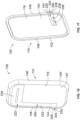
Figure 16 is an outer view of a portion of the casing showing the antenna in accordance with an exemplary embodiment. -
Figure 17 is an inner view of a portion of the casing showing the antenna in accordance with an exemplary embodiment. -
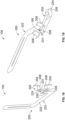
Figure 18 is an enlarged view of a portion of the wireless ear computer showing the antenna in accordance with an exemplary embodiment. -
Figure 19 is an enlarged view of a portion of the wireless ear computer showing the antenna in accordance with an exemplary embodiment. -
Figure 20 is an outer end view of a portion of the wireless ear computer showing the antenna in accordance with an exemplary embodiment. -
Figure 21 is an inner end view of a portion of the wireless ear computer showing the antenna in accordance with an exemplary embodiment. -
Figure 1 is a front perspective view of thewireless ear computer 100 in accordance with an exemplary embodiment.Figure 2 is a rear perspective view of thewireless ear computer 100 in accordance with an exemplary embodiment. Thewireless ear computer 100 is a wearable device configured be worn in the ear of a user. For example, thewireless ear computer 100 is a wireless earphone in various embodiments. Thewireless ear computer 100 includes anantenna 200 providing wireless communication, such as with a portable device, such as a smart phone or other handheld device. Theantenna 200 provides stable wireless connection with the portable device. The antenna design takes into consideration the complex device structure of thewireless ear computer 100, the small size constraints of thewireless ear computer 100, and the close human ear condition of thewireless ear computer 100 to provide good antenna performance for wireless connection with the portable device. - The
wireless ear computer 100 includes acasing 110 forming acavity 112 holding the internal electronics of thewireless ear computer 100. In an exemplary embodiment, thecasing 110 includes amain body 114 forming thecavity 112 and at least onecover 116 to close thecavity 112. Theantenna 200 may be provided on themain body 114 and/or thecover 116. Thecasing 110 extends between a top 120 and a bottom 122. Thecasing 110 extends between aninner end 124 and anouter end 126. Thecover 116 may be provided at theouter end 126. Aplug portion 128 is provided at theinner end 124 and is configured to be plugged into the ear of the user. Rubber tips may be provided on theplug portion 128 to plug into the ear of the user. Thecasing 110 extends between a front 136 and a rear 138. Thecasing 110 may be a multi-piece casing, such as a clamshell type casing. The pieces may be secured together using fasteners. Other types of securing features may be used in alternative embodiments, such as clips, latches, adhesive, or other securing features. - While the
casing 110 is shown as generally box shaped having theplug portion 128 extending therefrom, such as at a downward and inward angle, it is realized that thecasing 110 may have other shapes in alternative embodiments. For example, thecasing 110 may be contoured to fit within the user's ear. The internal electronic components of thewireless ear computer 100 are designed to fit within thecavity 112 of thecasing 110 and extend into theplug portion 128 to deliver sound to the user's ear. Theantenna 200 is integrated with the internal electronics of thewireless ear computer 100 and is patterned and positioned to provide robust performance. In the illustrated embodiment, theantenna 200 extends along theouter end 126 of thecasing 110, such as to locate theantenna 200 furthest from the user's ear. The shape of the pattern of theantenna 200 is located based on the positioning of the internal electronics to provide robust performance. -
Figure 3 is a perspective view of the internalelectronic components 102 of thewireless ear computer 100 in accordance with an exemplary embodiment.Figure 4 is an end view of the internalelectronic components 102 of thewireless ear computer 100 in accordance with an exemplary embodiment.Figure 5 is a side view of the internalelectronic components 102 of thewireless ear computer 100 in accordance with an exemplary embodiment. The casing 110 (Figures 1-2 ) is removed to illustrate the internalelectronic components 102. The internalelectronic components 102 are configured to be tightly packaged within thecasing 110. - In an exemplary embodiment, the internal
electronic components 102 include abattery 104 and aspeaker 106. Other types of internalelectronic components 102 may additionally be included, such as a microphone, sensors (for example, touch sensors, motion sensors, and the like), indicators, or other types of electronic components. - In an exemplary embodiment, the
wireless ear computer 100 includes acontrol module 150 for controlling operation of theelectronic components 102. Thecontrol module 150 includes aflexible circuit 152 havingvarious circuit components 154 for controlling thewireless ear computer 100. Thebattery 104 is connected to theflexible circuit 152, such as to a power circuit (battery circuit) that provides power to other components from thebattery 104. Thespeaker 106 is connected to theflexible circuit 152, such as to a speaker circuit that controls operation of thespeaker 106. In an exemplary embodiment, the antenna 200 (Figure 5 ) is connected to thecontrol module 150. For example, theantenna 200 may be connected to atransceiver 156 of thecircuit components 154. Theantenna 200 may be connected to an RF front-end module 158 of thecircuit components 154. - In an exemplary embodiment, the
flexible circuit 152 includes aground plane 160. Theantenna 200 may be electrically connected to theground plane 160. Theelectronic components 102 may be electrically connected to theground plane 160. Thecircuit components 154 may be electrically connected to theground plane 160. Electrically connecting the various components to theground plane 160 may enhance the performance of theantenna 200, such as providing a common or ground for all of the electrically conductive components of thewireless ear computer 100. - In an exemplary embodiment, the
flexible circuit 152 surrounds acomponent pocket 162. For example, theflexible circuit 152 may extend along the multiple sides of thecomponent pocket 162 to connect the various components located at various positions within thecasing 110. In an exemplary embodiment, theflexible circuit 152 includesvarious panels 164 defining distinct portions of theflexible circuit 152. Thepanels 164 may be electrically connected by traces, contacts, or other connectingstructures 166. One or more of thepanels 164 may be continuous with each other. In the illustrated embodiment, theflexible circuit 152 includes aninner portion 152a, anouter portion 152b, anupper portion 152c, alower portion 152d, and afront portion 152e. Theflexible circuit 152 may include greater or fewer portions in alternative embodiments, such as a rear portion (not shown). In an exemplary embodiment, thepanels 164 and the connectingstructures 166 are manufactured from a single substrate, such as a flexible printed circuit board having various circuits formed on thepanels 164 and the connectingstructures 166. - In an exemplary embodiment, various components are located within the
component pocket 162. For example, thebattery 104 may be located within thecomponent pocket 162. The RF front-end module 158 and/or thetransceiver 156 may be located within thecomponent pocket 162. As such, theground plane 160 of theflexible circuit 152 may surround the components of thewireless ear computer 100. In various embodiments, theflexible circuit 152 is fitted to thecasing 110, such as to extend along the interior surface of thecasing 110 to define as large of acomponent pocket 162 as practical. However, in other embodiments, other components may be located between theflexible circuit 152 and the inner surface of thecasing 110. -
Figure 6 is a schematic view of a side (for example, front side) of thewireless ear computer 100 in accordance with an exemplary embodiment.Figure 7 is a schematic view of an end (for example, top end) of thewireless ear computer 100 in accordance with an exemplary embodiment.Figures 6 and 7 show the internalelectronic components 102 and theantenna 200 in accordance with an exemplary embodiment. - The
flexible circuit 152 surrounds thecomponent pocket 162. The components are located within thecomponent pocket 162. For example, thebattery 104 is located within thecomponent pocket 162. Terminals of thebattery 104 may be electrically connected to theflexible circuit 152. Other components may additionally be located within thecomponent pocket 162. Theantenna 200 is connected to theflexible circuit 152. For example, theantenna 200 may be electrically connected to the ground plane of theflexible circuit 152. - In an exemplary embodiment, the
antenna 200 includes anantenna feed 202 and anantenna ground 204 connected to anantenna element 210 configured to receive and/or transmit signals. In an exemplary embodiment, atransmission line 168 is connected to theantenna feed 202 of theantenna 200. In an exemplary embodiment, theantenna 200 is an inverted F antenna (IFA). The IFA includes a monopole antenna, defined by theantenna element 210, running parallel to theground plane 160 and grounded at one end by theantenna ground 204. Theground plane 160 may be a layer of theflexible circuit 152, such as an outer layer or an inner layer. Theantenna element 210 is fed by theantenna feed 202 at an intermediate point a distance from theantenna ground 204. Theantenna 200 is short and compact allowing theantenna 200 to be contained within thecasing 110 of thewireless ear computer 100. In an exemplary embodiment, theantenna 200 is positioned relative to the internalelectronic components 102 and is patterned or shaped to provide impedance matching within the antenna circuit. Theantenna 200 radiates efficiently without the need for extraneous matching components. Theantenna 200 may be a planar inverted F antenna (PIFA), which may be printed in a microstrip format on thecasing 110. -
Figure 8 is a schematic view of an end (for example, top end) of thewireless ear computer 100 in accordance with an exemplary embodiment.Figure 9 is a schematic view of a portion of thewireless ear computer 100 in accordance with an exemplary embodiment showing the connection of theantenna 200.Figure 8 shows the internalelectronic components 102 and theantenna 200 in accordance with an exemplary embodiment. - In an exemplary embodiment, the
transmission line 168 is connected between theantenna 200 and the RF front-end module 158. For example, thetransmission line 168 may be a flexible circuit or a coaxial cable extending between the RF front-end module 158 and theantenna 200. Theantenna feed 202 is connected to a transmission feed of thetransmission line 168. Theantenna ground 204 is connected to a transmission ground of thetransmission line 168. For example, the transmission feed may be an inner conductor of the coaxial cable and the transmission ground may be an outer conductor of the coaxial cable. In other embodiments, the transmission feed may be a first trace or pad on the transmission flexible circuit and the transmission ground may be a second trace or pad on the transmission flexible circuit. - In an exemplary embodiment, a
ground conductor 170 is provided between theantenna ground 204 and theground plane 160. Theground conductor 170 may be a solder connection between the transmission ground and theground plane 160 and/or theantenna ground 204. In other various embodiments, theground conductor 170 may be a stamped and formed contact, such as a spring contact, between the transmission ground and theground plane 160 and/or theantenna ground 204. In other various embodiments, theground conductor 170 may be a conductive foam that is compressible between the transmission ground and theground plane 160 and/or theantenna ground 204. In further embodiments, theground conductor 170 may be a conductive tape between the transmission ground and theground plane 160 and/or theantenna ground 204. -
Figure 10 is an outer end view of a portion of thewireless ear computer 100 showing the internalelectronic components 102 and theantenna 200 in accordance with an exemplary embodiment.Figure 11 is a front view of a portion of thewireless ear computer 100 showing the internalelectronic components 102 in theantenna 200 in accordance with an exemplary embodiment. The casing 110 (Figure 1 ) is removed to illustrate theantenna 200 relative to the internalelectronic components 102. - The
flexible circuit 152 surrounds thecomponent pocket 162. The components are located within thecomponent pocket 162. For example, thebattery 104, thetransceiver 156, and the RF front-end module 158 are located within thecomponent pocket 162. For example, thebattery 104 may be located between theinner portion 152a and theouter portion 152b of theflexible circuit 152. Terminals of thebattery 104 may be electrically connected to theflexible circuit 152. Thetransceiver 156 may be located at theupper portion 152c of theflexible circuit 152. The RF front-end module 158 may be located at theinner portion 152a of theflexible circuit 152. - In an exemplary embodiment, the
transmission line 168 is connected between the RF front-end module 158 and theantenna 200. In the illustrated embodiment, thetransmission line 168 is part of theflexible circuit 152. However, thetransmission line 168 may be a separate flexible circuit in alternative embodiments. In other various embodiments, thetransmission line 168 may include a coaxial cable routed between the RF front-end module 158 and theantenna 200. Thetransmission line 168 may include a stamped and formed contact, such as a spring contact, between the RF front-end module 158 and theantenna 200 in other various embodiments. Thetransmission line 168 may include other types of contacts or conductors in alternative embodiments, such as a spring, conductive foam, conductive gasket, a conductive tape, a conductive polymer contact, wire contact, pin contact, or other type of conductor. In the illustrated embodiment, thetransmission line 168 is provided at thefront portion 152e of theflexible circuit 152. Thetransmission line 168 extends between the inner end and the outer end to connect the RF front-end module 158 and theantenna 200. Other locations are possible in alternative embodiments - In an exemplary embodiment, the
antenna 200 includes anantenna feed 202 and anantenna ground 204 connected to anantenna element 210 configured to receive and/or transmit signals. Theantenna feed 202 is configured to be connected to thetransmission line 168. For example, theantenna feed 202 includes afeed post 206 electrically connected to thetransmission line 168. Theantenna ground 204 is configured to be electrically connected to theground plane 160 of theflexible circuit 152. For example, theantenna ground 204 includes aground post 208 electrically connected to theground plane 160. - In an exemplary embodiment, the
antenna 200 includes aninner portion 220 configured to be located within thecavity 112 of thecasing 110, anouter portion 222 configured to be located outside of thecasing 110, and a connectingportion 224 between theinner portion 220 and theouter portion 222. For example, the connectingportion 224 may extend through thecasing 110 or around an edge surface of thecasing 110 to connect theinner portion 220 and theouter portion 222. Theinner portion 220 is located in close proximity to theflexible circuit 152 to electrically connect to theflexible circuit 152. For example, theantenna feed 202 and theantenna ground 204 may be provided along theinner portion 220. Theouter portion 222 is located remote from theflexible circuit 152. Theouter portion 222 is spaced apart from theground plane 160 of theflexible circuit 152 to reduce interference and improve antenna signaling (for example, transmit and receive) of theantenna 200. In various embodiments, theinner portion 220 extends along an interior surface of thecasing 110 and/or thecover 116 and theouter portion 222 extends along an exterior surface of thecasing 110 and/or thecover 116. - In an exemplary embodiment, a
ground conductor 170 is provided between theantenna ground 204 and theground plane 160. Theground conductor 170 may be a solder connection between theground post 208 and a pad or conductor on theflexible circuit 152 connected to theground plane 160. In other various embodiments, theground conductor 170 may be a stamped and formed contact, such as a spring contact, between theflexible circuit 152 and theground post 208. In other various embodiments, theground conductor 170 may be a conductive foam that is compressible between theground post 208 and theflexible circuit 152. In further embodiments, theground conductor 170 may be a conductive tape between theground post 208 and theflexible circuit 152. In other various embodiments, theground conductor 170 may be a cable shield or outer conductor of a coaxial conductor connected between theantenna ground 204 and theflexible circuit 152 or another component, such as the RF front-end module 158. - In an exemplary embodiment, the
antenna 200 is an inverted F antenna (IFA). The IFA includes a monopole antenna, defined by theantenna element 210, running parallel to theground plane 160 and grounded at one end by theantenna ground 204. Theantenna element 210 is fed by theantenna feed 202 at an intermediate point a distance from theantenna ground 204. Theantenna 200 is short and compact allowing theantenna 200 to be contained within thecasing 110 of thewireless ear computer 100. In an exemplary embodiment, theantenna 200 is positioned relative to the internalelectronic components 102 and is patterned or shaped to provide impedance matching within the antenna circuit. Theantenna 200 radiates efficiently without the need for extraneous matching components. Theantenna 200 may be a planar inverted-F antenna (PIFA), which may be printed in a microstrip format on thecasing 110. -
Figure 12 is a schematic view of theantenna 200 in accordance with an exemplary embodiment.Figure 12 shows theantenna feed 202, theantenna ground 204 and theantenna element 210 extending from theantenna feed 202 and theantenna ground 204. Theantenna feed 202 and theantenna ground 204 are provided at theinner portion 220 of theantenna 200.Antenna element 210 is provided at theouter portion 222 of theantenna 200. - In an exemplary embodiment, the
antenna 200 includes afeed line 230, amain line 232, and abranch line 234. Themain line 232 extends between thefeed line 230 and thebranch line 234. Thefeed line 230 connects theantenna feed 202 and theantenna ground 204 to themain line 232. In an exemplary embodiment, thefeed line 230 includes a connectingline 231 directly connecting thefeed post 206 and theground post 208. The connectingline 231 directly connects thefeed post 206 and theground post 208. In various embodiments, themain line 232 extends along one side of the antenna 200 (for example, along a front side) while thefeed line 230 is provided at a bottom of theantenna 200 and thebranch line 234 is provided at the top of the antenna. Themain line 232 spaces thebranch line 234 apart from thefeed line 230. Thebranch line 234 extends between a front and a rear of theantenna 200. Other orientations are possible in alternative embodiments. - In an exemplary embodiment, the
branch line 234 includes afirst branch 236, atail 235 extending from a distal end of thefirst branch 236, and asecond branch 238. Thetail 235 connects thefirst branch 236 and thesecond branch 238. In the illustrated embodiment, thefirst branch 236 is parallel to thesecond branch 238. Aslot 237 is formed between the first andsecond branches slot 237 has a width between themain line 232 and thetail 235. The widths and lengths of thebranches antenna 200, such as operating frequencies of theantenna 200. The width and length of theslot 237 controls antenna characteristics of theantenna 200, such as operated frequencies of theantenna 200. Thebranch line 234 may include additional branches in alternative embodiments. Thebranches 236 and/or 238 may follow nonlinear paths in alternative embodiments, such as meandering paths. -
Figure 13 is a schematic view of theantenna 200 in accordance with an exemplary embodiment.Figure 13 shows theantenna feed 202, theantenna ground 204 and theantenna element 210 extending from theantenna feed 202 and theantenna ground 204. In the illustrated embodiment, theantenna 200 is similar to the antenna shown inFigure 12 ; however, theantenna 200 is provided without thesecond branch 238 to provide different antenna characteristics. Rather, thebranch line 234 includes thefirst branch 236 and thetail 235. Thesecond branch 238 may be removed to position theantenna 200 further from another structure, such as one of the internal components of thewireless ear computer 100. For example, thesecond branch 238 may be removed to position theantenna 200 further from the ground plane. -
Figure 14 is a schematic view of theantenna 200 in accordance with an exemplary embodiment.Figure 14 shows theantenna feed 202, theantenna ground 204 and theantenna element 210 extending from theantenna feed 202 and theantenna ground 204. In the illustrated embodiment, theantenna 200 is similar to the antenna shown inFigure 12 ; however, theantenna 200 is provided without thesecond branch 238 and without thetail 235 to provide different antenna characteristics. Rather, thebranch line 234 includes thefirst branch 236. -
Figure 15 is a schematic view of theantenna 200 in accordance with an exemplary embodiment.Figure 15 shows theantenna feed 202, theantenna ground 204 and theantenna element 210 extending from theantenna feed 202 and theantenna ground 204. In the illustrated embodiment, theantenna 200 is similar to the antenna shown inFigure 12 ; however, theantenna 200 is provided without thefirst branch 236 and without thetail 235 to provide different antenna characteristics. Rather, thebranch line 234 includes thesecond branch 238. Thefirst branch 236 may be removed to position theantenna 200 further from another structure, such as one of the internal components of thewireless ear computer 100. For example, thefirst branch 236 may be removed to position theantenna 200 further from the ground plane. -
Figure 16 is an outer view of a portion of thecasing 110 showing theantenna 200 in accordance with an exemplary embodiment.Figure 17 is an inner view of a portion of thecasing 110 showing theantenna 200 in accordance with an exemplary embodiment.Figures 16 and 17 illustrate thecover 116 of thecasing 110 showing the positioning of theantenna 200 on thecover 116. - In an exemplary embodiment, the
antenna 200 is provided directly on surfaces of thecover 116. For example, theantenna 200 may be applied directly to thecover 116. In various embodiments, theantenna 200 is plated or coated oncover 116. Theantenna 200 may be applied by a laser direct structuring (LDS) process in various embodiments. Theantenna 200 may be a microstrip applied to thecover 116. In various embodiments, theantenna 200 or portions of theantenna 200 may be embedded within and/or pass through thecover 116. - The
cover 116 includes an interior surface 140 (Figure 17 ) and an exterior surface 142 (Figure 16 ). Theinner portion 220 of theantenna 200 is provided on theinterior surface 140. Theouter portion 222 of theantenna 200 is provided on theexterior surface 142. The connectingportion 224 connects theinner portion 220 and theouter portion 222. In an exemplary embodiment, the connectingportion 224 includes aside trace 226 connecting theinner portion 220 and theouter portion 222. For example, the connectingportion 224 extends along anedge 144 of thecover 116, which extends between theinterior surface 140 and theexterior surface 142. Theside trace 226 is routed along surfaces (inner/edge/outer) of thecover 116. In various embodiments, the connectingportion 224 may additionally, or alternatively, include a through trace (not shown) connecting theinner portion 220 and theouter portion 222. The through trace may extend internally through thecover 116. For example, the through trace may be a plated or filled via passing through thecover 116. - The
feed line 230 of theantenna 200 extends along theinterior surface 140 between the feed post 206 (Figure 11 ) and the ground post 208 (Figure 11 ). Thefeed post 206 and theground post 208 may be defined by post like structures molded or formed into thecover 116. Alternatively, thefeed post 206 and/or theground post 208 may be defined by a contact or wire coupled to thefeed line 230. In the illustrated embodiment, thefeed line 230 is located proximate to the bottom of thecover 116. Themain line 232 extends along theexterior surface 142, such as along aside 146 of thecover 116. Thebranch line 234 extends along theexterior surface 142 from themain line 232. Thebranch line 234 may extend from theside 146 two andopposite sides 148 of thecover 116. In an exemplary embodiment, a large portion of thecover 116 is devoid of the antenna structure. Rather, the pattern of theantenna 200 is designed to extend along certain areas of thecover 116 and avoid other areas of thecover 116, such as to avoid interference by the internalelectronic components 102 within the interior of thewireless ear computer 100. -
Figure 18 is an enlarged view of a portion of thewireless ear computer 100 showing theantenna 200 in accordance with an exemplary embodiment. Theinner portion 220 of theantenna 200 extends into the interior of the casing 110 (shown inFigures 16 and 17 ) while theouter portion 222 of theantenna 200 extends along the exterior of thecasing 110. The connectingportion 224 extends between theinner portion 220 and theouter portion 222. - The
feed post 206 of theantenna feed 202 is connected to thetransmission line 168. Theground post 208 of theantenna ground 204 is connected to theground conductor 170. The connectingline 231 of thefeed line 230 directly connects theground post 208 and thefeed post 206. A throughtrace 228 of the connectingportion 224 extends from the connectingline 231 to themain line 232. As such, themain line 232 is connected to theantenna feed 202 and theantenna ground 204 by thefeed line 230 and the throughtrace 228. The throughtrace 228 connects theinner portion 220 and theouter portion 222. The throughtrace 228 may extend internally through thecover 116. For example, the throughtrace 228 may be a plated or filled via passing through thecover 116. Optionally, the throughtrace 228 may be connected to the connectingline 231 approximately centered between thefeed post 206 and theground post 208. The location of the connection along the connectingline 231 may control the antenna characteristics of theantenna 200. For example, connecting closer to thefeed post 206 versus closer to theground post 208 may affect the operating frequency of theantenna 200. Thefeed post 206 at theantenna feed 202 may be connected to theground post 208 of theantenna ground 204 by the connectingline 231. The connectingline 231 may be connected to themain line 232 by the throughtrace 228 of the connectingportion 224. -
Figure 19 is an enlarged view of a portion of thewireless ear computer 100 showing theantenna 200 in accordance with an exemplary embodiment. Theantenna 200 shown inFigure 19 is similar to the antenna shown inFigure 18 ; however, the connectingportion 224 includes the throughtrace 228 in addition to theside trace 226. The throughtrace 228 extends between theinner portion 220 and theouter portion 222 through an opening or via 180 of the casing. The throughtrace 228 and theside trace 226 are electrically connected to the connectingline 231 of theinner portion 220, and they may both connect the connectingline 231 to themain line 232. Optionally, the throughtrace 228 may be connected to the connectingline 231 approximately centered between thefeed post 206 and theground post 208. The location of the connection along the connectingline 231 may control the antenna characteristics of theantenna 200. For example, connecting closer to thefeed post 206 versus closer to theground post 208 may affect the operating frequency of theantenna 200. Theside trace 226 may be connected to the connectingline 231 at an end of the connectingline 231. Thefeed post 206 at theantenna feed 202 may be connected to theouter portion 222 by theside trace 226 of the connectingportion 224. Theground post 208 of theground feed 202 may be connected to theouter portion 222 by the throughtrace 228 of the connectingportion 224. -
Figure 20 is an outer end view of a portion of thewireless ear computer 100 showing theantenna 200 in accordance with an exemplary embodiment.Figure 21 is an inner end view of a portion of thewireless ear computer 100 showing theantenna 200 in accordance with an exemplary embodiment. Theantenna 200 is shown electrically connected to thetransmission line 168. In the illustrated embodiment, thetransmission line 168 is a flexible circuit. Thetransmission line 168 may be routed from one portion or area of thewireless ear computer 100 to the termination area of theantenna 200. In an exemplary embodiment, thetransmission line 168 is electrically connected to the RF front-end module 158 and routed to the antenna termination area. Theantenna feed 202 is electrically connected to a feed circuit of thetransmission line 168. Optionally, theantenna ground 204 may be electrically connected to a ground circuit of thetransmission line 168. - In various embodiments, the
ground conductor 170 is provided between thetransmission line 168 and theground plane 160. Theground conductor 170 may be electrically connected to a ground circuit of thetransmission line 168. Theground conductor 170 may be electrically connected to the RF front-end module 158 by thetransmission line 168. In the illustrated embodiment, theground conductor 170 is a stamped and formed contact, such as a spring contact, between thetransmission line 168 and theground plane 160 of theflexible circuit 152. Theground conductor 170 may additionally be electrically connected to theantenna ground 204 of theantenna 200. In alternative embodiments, theground conductor 170 may be a flexible circuit. In other various embodiments, theground conductor 170 may be a conductive foam or a conductive tape. - It is to be understood that the above description is intended to be illustrative, and not restrictive. For example, the above-described embodiments (and/or aspects thereof) may be used in combination with each other. In addition, many modifications may be made to adapt a particular situation or material to the teachings of the invention without departing from its scope. Dimensions, types of materials, orientations of the various components, and the number and positions of the various components described herein are intended to define parameters of certain embodiments, and are by no means limiting and are merely exemplary embodiments. Many other embodiments and modifications within the spirit and scope of the claims will be apparent to those of skill in the art upon reviewing the above description. The scope of the invention should, therefore, be determined with reference to the appended claims, along with the full scope of equivalents to which such claims are entitled. In the appended claims, the terms "including" and "in which" are used as the plain-English equivalents of the respective terms "comprising" and "wherein." Moreover, in the following claims, the terms "first," "second," and "third," etc. are used merely as labels, and are not intended to impose numerical requirements on their objects. Further, the limitations of the following claims are not written in means-plus-function format and are not intended to be interpreted based on 35 U.S.C. § 112(f), unless and until such claim limitations expressly use the phrase "means for" followed by a statement of function void of further structure.
Claims (15)
- A wireless ear computer (100) comprising:a casing (110) forming a cavity (112);a flexible circuit (152) received in the cavity, the flexible circuit surrounding a component pocket (162) configured to receive at least one electrical component (156, 158), the flexible circuit (152) having a power circuit, the flexible circuit including a ground plane (160);a battery (104) received in the component pocket (162), the battery operably coupled to the power circuit to power the at least one electrical component (156, 158), the battery (104) connected to the ground plane (160) of the flexible circuit;an antenna (200) having an antenna element (210) extending along the casing (110), the antenna element being spaced apart from, and located outward of, the flexible circuit (152), the antenna including an antenna feed (202) and an antenna ground (204), the antenna ground (204) being connected to the ground plane (160) of the flexible circuit.
- The wireless ear computer of claim 1, wherein the casing (110) includes an interior surface (140) and an exterior surface (142), the antenna element (210) including an inner portion (220) extending along the interior surface (140) and an outer portion (222) extending along the exterior surface (142), the antenna element (210) including a connecting portion (224) between the inner portion and the outer portion.
- The wireless ear computer of claim 2, wherein the connecting portion (224) includes a side trace (226) wrapping around the side of the casing (110) from the interior surface (140) to the exterior surface (142).
- The wireless ear computer of claim 2 or 3, wherein the connecting portion (224) includes a through trace (228) extending through the casing (110) between the interior surface (140) and the exterior surface (142).
- The wireless ear computer of claim 2, 3 or 4, wherein the antenna feed includes a feed post (206) connected to a transmission line (168) and the antenna ground includes a ground post (208) connected to the ground plane (160) of the flexible circuit (152), the connecting portion or the inner portion (220) including a connecting line (231) between the feed post (206) and the ground post (208) directly connecting the antenna feed (202) and the ground feed (204).
- The wireless ear computer of claim 5, wherein the connecting portion includes a through line (228) connecting the connecting line (231) and the outer portion (222) of the antenna.
- The wireless ear computer of any preceding claim, wherein the flexible circuit (152) extends circumferentially around the component pocket (162), preferably extending over at least two directly opposing sides of the component pocket (162).
- The wireless ear computer of any preceding claim, wherein the antenna element includes a feed line (230), a branch line (234), and a main line (232) between the feed line and the branch line, the feed line connecting the antenna feed (202) and the antenna ground (204) to the main line, the main line (232) extending between a top (120) and a bottom (122) of the casing (110), the branch line (234) extending from the main line (232) between an outer end (126) and an inner end (124) of the casing.
- The wireless ear computer of claim 8, wherein the branch line (234) includes a first branch (236) and a second branch spaced (238) apart from the first branch and extending between the outer end (126) and the inner end (124) of the casing.
- The wireless ear computer of any preceding claim, wherein the flexible circuit (152) includes a transceiver (156), wherein an RF front-end module (158) is operably coupled to the transceiver, the antenna feed (202) of the antenna being connected to the RF front-end module (158), the RF front-end module (158) preferably coupled to the flexible circuit (152).
- The wireless ear computer of claim 10, wherein the antenna further comprises a transmission line (168) between the RF front-end module (158) and the antenna feed (202), the transmission line being one of a coaxial cable, a flexible circuit, or a spring contact.
- The wireless ear computer of claim 10 or 11, wherein the antenna ground (204) is connected to the RF front-end module.
- The wireless ear computer of claim 10, 11 or 12, wherein the antenna element (210) is located at a first side (126) of the casing, the RF front-end module (158) being located at a different second side (136) of the casing.
- The wireless ear computer of any preceding claim, wherein the antenna includes a ground conductor (170) between the antenna ground (204) and the ground plane (160), the ground conductor (170) being one of a solder connection, a spring contact, a conductive foam, or a conductive tape.
- The wireless ear computer of any preceding claim, wherein the flexible circuit (152) has a speaker circuit, and wherein a speaker (106) is operably coupled to the speaker circuit to control the speaker, the speaker connected to the ground plane (160) of the flexible circuit.
Applications Claiming Priority (2)
| Application Number | Priority Date | Filing Date | Title |
|---|---|---|---|
| US202263433393P | 2022-12-16 | 2022-12-16 | |
| US18/480,872 US20240204390A1 (en) | 2022-12-16 | 2023-10-04 | Antenna assembly for a wireless ear computer |
Publications (1)
| Publication Number | Publication Date |
|---|---|
| EP4386980A1 true EP4386980A1 (en) | 2024-06-19 |
Family
ID=89222784
Family Applications (1)
| Application Number | Title | Priority Date | Filing Date |
|---|---|---|---|
| EP23216386.5A Pending EP4386980A1 (en) | 2022-12-16 | 2023-12-13 | Antenna assembly for a wireless ear computer |
Country Status (5)
| Country | Link |
|---|---|
| US (1) | US20240204390A1 (en) |
| EP (1) | EP4386980A1 (en) |
| JP (1) | JP2024086644A (en) |
| KR (1) | KR20240095064A (en) |
| TW (1) | TW202429909A (en) |
Cited By (1)
| Publication number | Priority date | Publication date | Assignee | Title |
|---|---|---|---|---|
| EP4765483A1 (en) * | 2024-12-23 | 2026-06-24 | Starkey Laboratories, Inc. | Antenna structure with in-line harmonic filter for hearing instruments |
Families Citing this family (1)
| Publication number | Priority date | Publication date | Assignee | Title |
|---|---|---|---|---|
| WO2026014809A1 (en) * | 2024-07-08 | 2026-01-15 | 삼성전자 주식회사 | Wearable electronic device |
Citations (6)
| Publication number | Priority date | Publication date | Assignee | Title |
|---|---|---|---|---|
| US20200021905A1 (en) * | 2018-07-10 | 2020-01-16 | New Audio LLC | Wireless earpiece having antenna with wall-embedded radiating element and related technology |
| US10972824B1 (en) * | 2019-11-12 | 2021-04-06 | Merry Electronics (Shenzhen) Co., Ltd. | Wireless earphone |
| US20220021989A1 (en) * | 2019-04-01 | 2022-01-20 | Starkey Laboratories, Inc. | Ear-worn electronic device incorporating magnetically coupled feed for an antenna |
| US20220159363A1 (en) * | 2019-06-29 | 2022-05-19 | Huawei Technologies Co., Ltd. | Bluetooth Earphone |
| WO2022165033A1 (en) * | 2021-01-27 | 2022-08-04 | New Audio LLC | Wireless earpiece with external antenna features and related technology |
| US20220278442A1 (en) * | 2019-11-22 | 2022-09-01 | Goertek Technology Co., Ltd. | Antenna, wireless earbud and electronic device |
Family Cites Families (13)
| Publication number | Priority date | Publication date | Assignee | Title |
|---|---|---|---|---|
| US9635475B2 (en) * | 2013-05-01 | 2017-04-25 | Starkey Laboratories, Inc. | Hearing assistance device with balanced feed-line for antenna |
| US20150116162A1 (en) * | 2013-10-28 | 2015-04-30 | Skycross, Inc. | Antenna structures and methods thereof for determining a frequency offset based on a differential magnitude |
| US9491880B2 (en) * | 2014-08-12 | 2016-11-08 | Google Technology Holdings LLC | Circuit assembly for compact acoustic device |
| US10321593B1 (en) * | 2016-04-13 | 2019-06-11 | Vorbeck Materials Corp. | Interconnect device |
| WO2018113927A1 (en) * | 2016-12-20 | 2018-06-28 | Sonova Ag | Bte hearing instrument comprising a loop antenna |
| US10944156B2 (en) * | 2017-09-29 | 2021-03-09 | Apple Inc. | Wireless earphone antennas |
| US10916830B2 (en) * | 2018-02-17 | 2021-02-09 | Bose Corporation | Earbud system |
| US11355834B2 (en) * | 2019-02-06 | 2022-06-07 | Starkey Laboratories, Inc. | Ear-worn electronic device incorporating an antenna substrate comprising a dielectric gel or liquid |
| US10944157B2 (en) * | 2019-04-19 | 2021-03-09 | Bose Corporation | Multi-arm spiral antenna for a wireless device |
| CN112752180B (en) * | 2019-10-31 | 2022-08-26 | 华为技术有限公司 | Bluetooth earphone |
| WO2021097783A1 (en) * | 2019-11-22 | 2021-05-27 | Goertek Technology Co., Ltd. | Antenna and wireless earbud comprising the same |
| EP3890352A1 (en) * | 2020-03-30 | 2021-10-06 | GN Hearing A/S | Hearing device with an antenna |
| CN117793594A (en) * | 2020-09-10 | 2024-03-29 | 华为技术有限公司 | Wireless Headphones |
-
2023
- 2023-10-04 US US18/480,872 patent/US20240204390A1/en active Pending
- 2023-12-13 JP JP2023209761A patent/JP2024086644A/en active Pending
- 2023-12-13 EP EP23216386.5A patent/EP4386980A1/en active Pending
- 2023-12-13 TW TW112148387A patent/TW202429909A/en unknown
- 2023-12-15 KR KR1020230183380A patent/KR20240095064A/en active Pending
Patent Citations (6)
| Publication number | Priority date | Publication date | Assignee | Title |
|---|---|---|---|---|
| US20200021905A1 (en) * | 2018-07-10 | 2020-01-16 | New Audio LLC | Wireless earpiece having antenna with wall-embedded radiating element and related technology |
| US20220021989A1 (en) * | 2019-04-01 | 2022-01-20 | Starkey Laboratories, Inc. | Ear-worn electronic device incorporating magnetically coupled feed for an antenna |
| US20220159363A1 (en) * | 2019-06-29 | 2022-05-19 | Huawei Technologies Co., Ltd. | Bluetooth Earphone |
| US10972824B1 (en) * | 2019-11-12 | 2021-04-06 | Merry Electronics (Shenzhen) Co., Ltd. | Wireless earphone |
| US20220278442A1 (en) * | 2019-11-22 | 2022-09-01 | Goertek Technology Co., Ltd. | Antenna, wireless earbud and electronic device |
| WO2022165033A1 (en) * | 2021-01-27 | 2022-08-04 | New Audio LLC | Wireless earpiece with external antenna features and related technology |
Cited By (1)
| Publication number | Priority date | Publication date | Assignee | Title |
|---|---|---|---|---|
| EP4765483A1 (en) * | 2024-12-23 | 2026-06-24 | Starkey Laboratories, Inc. | Antenna structure with in-line harmonic filter for hearing instruments |
Also Published As
| Publication number | Publication date |
|---|---|
| US20240204390A1 (en) | 2024-06-20 |
| KR20240095064A (en) | 2024-06-25 |
| TW202429909A (en) | 2024-07-16 |
| JP2024086644A (en) | 2024-06-27 |
Similar Documents
| Publication | Publication Date | Title |
|---|---|---|
| US10284942B2 (en) | Antennas for wireless earbuds | |
| US7289069B2 (en) | Wireless device antenna | |
| EP2276108B1 (en) | Electronic devices with parasitic antenna resonating elements that reduce near field radiation | |
| US20240204390A1 (en) | Antenna assembly for a wireless ear computer | |
| US7864116B2 (en) | Mounting structure of antenna device | |
| JP2004159288A (en) | Antenna device, printed wiring board, printed circuit board, communication adapter, and portable electronic device | |
| CN112582787B (en) | Antenna structure and electronic equipment | |
| KR101335824B1 (en) | Mobile terminal | |
| KR20040081120A (en) | Emc-arrangement for a device employing wireless data transfer | |
| US6340952B1 (en) | Induced loop antenna | |
| CN211152171U (en) | Intelligent Bluetooth earphone | |
| JP4379004B2 (en) | Communication adapter and portable electronic device | |
| KR101065277B1 (en) | Wrist watch terminal and antenna for it | |
| JP2000269718A (en) | Antenna and mobile terminal device | |
| CN109037908B (en) | Antenna system of mobile terminal and mobile terminal | |
| JP2014022785A (en) | Portable terminal | |
| TWI573322B (en) | Antenna assembly and wireless communication device employing same | |
| JP4870002B2 (en) | Antenna device | |
| JP4955428B2 (en) | Antenna device | |
| CN118213742A (en) | Antenna assembly for wireless ear computer | |
| JP2004215149A (en) | Antenna | |
| CN1964132B (en) | Hidden Multi-Band Antennas for Portable Devices | |
| CN223993727U (en) | Bluetooth earphone | |
| TWI523313B (en) | Electronic device | |
| KR101782955B1 (en) | Antenna structure |
Legal Events
| Date | Code | Title | Description |
|---|---|---|---|
| PUAI | Public reference made under article 153(3) epc to a published international application that has entered the european phase |
Free format text: ORIGINAL CODE: 0009012 |
|
| STAA | Information on the status of an ep patent application or granted ep patent |
Free format text: STATUS: THE APPLICATION HAS BEEN PUBLISHED |
|
| AK | Designated contracting states |
Kind code of ref document: A1 Designated state(s): AL AT BE BG CH CY CZ DE DK EE ES FI FR GB GR HR HU IE IS IT LI LT LU LV MC ME MK MT NL NO PL PT RO RS SE SI SK SM TR |
|
| STAA | Information on the status of an ep patent application or granted ep patent |
Free format text: STATUS: REQUEST FOR EXAMINATION WAS MADE |
|
| 17P | Request for examination filed |
Effective date: 20241122 |
|
| RBV | Designated contracting states (corrected) |
Designated state(s): AL AT BE BG CH CY CZ DE DK EE ES FI FR GB GR HR HU IE IS IT LI LT LU LV MC ME MK MT NL NO PL PT RO RS SE SI SK SM TR |