EP4386948A1 - Battery cover plate, battery, and energy storage device - Google Patents
Battery cover plate, battery, and energy storage device Download PDFInfo
- Publication number
- EP4386948A1 EP4386948A1 EP23746132.2A EP23746132A EP4386948A1 EP 4386948 A1 EP4386948 A1 EP 4386948A1 EP 23746132 A EP23746132 A EP 23746132A EP 4386948 A1 EP4386948 A1 EP 4386948A1
- Authority
- EP
- European Patent Office
- Prior art keywords
- pole
- hole
- cell cap
- mounting
- disposed
- Prior art date
- Legal status (The legal status is an assumption and is not a legal conclusion. Google has not performed a legal analysis and makes no representation as to the accuracy of the status listed.)
- Pending
Links
Images


Classifications
-
- H—ELECTRICITY
- H01—ELECTRIC ELEMENTS
- H01M—PROCESSES OR MEANS, e.g. BATTERIES, FOR THE DIRECT CONVERSION OF CHEMICAL ENERGY INTO ELECTRICAL ENERGY
- H01M50/00—Constructional details or processes of manufacture of the non-active parts of electrochemical cells other than fuel cells, e.g. hybrid cells
- H01M50/10—Primary casings; Jackets or wrappings
- H01M50/147—Lids or covers
- H01M50/148—Lids or covers characterised by their shape
-
- H—ELECTRICITY
- H01—ELECTRIC ELEMENTS
- H01M—PROCESSES OR MEANS, e.g. BATTERIES, FOR THE DIRECT CONVERSION OF CHEMICAL ENERGY INTO ELECTRICAL ENERGY
- H01M50/00—Constructional details or processes of manufacture of the non-active parts of electrochemical cells other than fuel cells, e.g. hybrid cells
- H01M50/10—Primary casings; Jackets or wrappings
- H01M50/172—Arrangements of electric connectors penetrating the casing
-
- H—ELECTRICITY
- H01—ELECTRIC ELEMENTS
- H01M—PROCESSES OR MEANS, e.g. BATTERIES, FOR THE DIRECT CONVERSION OF CHEMICAL ENERGY INTO ELECTRICAL ENERGY
- H01M50/00—Constructional details or processes of manufacture of the non-active parts of electrochemical cells other than fuel cells, e.g. hybrid cells
- H01M50/10—Primary casings; Jackets or wrappings
- H01M50/183—Sealing members
- H01M50/184—Sealing members characterised by their shape or structure
-
- H—ELECTRICITY
- H01—ELECTRIC ELEMENTS
- H01M—PROCESSES OR MEANS, e.g. BATTERIES, FOR THE DIRECT CONVERSION OF CHEMICAL ENERGY INTO ELECTRICAL ENERGY
- H01M50/00—Constructional details or processes of manufacture of the non-active parts of electrochemical cells other than fuel cells, e.g. hybrid cells
- H01M50/10—Primary casings; Jackets or wrappings
- H01M50/183—Sealing members
- H01M50/186—Sealing members characterised by the disposition of the sealing members
- H01M50/188—Sealing members characterised by the disposition of the sealing members the sealing members being arranged between the lid and terminal
-
- H—ELECTRICITY
- H01—ELECTRIC ELEMENTS
- H01M—PROCESSES OR MEANS, e.g. BATTERIES, FOR THE DIRECT CONVERSION OF CHEMICAL ENERGY INTO ELECTRICAL ENERGY
- H01M50/00—Constructional details or processes of manufacture of the non-active parts of electrochemical cells other than fuel cells, e.g. hybrid cells
- H01M50/50—Current conducting connections for cells or batteries
- H01M50/543—Terminals
-
- H—ELECTRICITY
- H01—ELECTRIC ELEMENTS
- H01M—PROCESSES OR MEANS, e.g. BATTERIES, FOR THE DIRECT CONVERSION OF CHEMICAL ENERGY INTO ELECTRICAL ENERGY
- H01M10/00—Secondary cells; Manufacture thereof
- H01M10/05—Accumulators with non-aqueous electrolyte
- H01M10/052—Li-accumulators
- H01M10/0525—Rocking-chair batteries, i.e. batteries with lithium insertion or intercalation in both electrodes; Lithium-ion batteries
-
- Y—GENERAL TAGGING OF NEW TECHNOLOGICAL DEVELOPMENTS; GENERAL TAGGING OF CROSS-SECTIONAL TECHNOLOGIES SPANNING OVER SEVERAL SECTIONS OF THE IPC; TECHNICAL SUBJECTS COVERED BY FORMER USPC CROSS-REFERENCE ART COLLECTIONS [XRACs] AND DIGESTS
- Y02—TECHNOLOGIES OR APPLICATIONS FOR MITIGATION OR ADAPTATION AGAINST CLIMATE CHANGE
- Y02E—REDUCTION OF GREENHOUSE GAS [GHG] EMISSIONS, RELATED TO ENERGY GENERATION, TRANSMISSION OR DISTRIBUTION
- Y02E60/00—Enabling technologies; Technologies with a potential or indirect contribution to GHG emissions mitigation
- Y02E60/10—Energy storage using batteries
Definitions
- This application relates to the field of cell technologies, and in particular, to a cell cap, a cell, and an energy storage device.
- Lithium-ion cells are widely used in products such as energy storage base stations, electric vehicles, and consumer electronics due to features of high energy, a long service life, no memory effect, a low self-discharge rate, and environmental friendliness.
- a pole in a conventional structure of a cell cap is formed by welding a column and a sheet that are separately disposed.
- the cell cap is complicated in assembly and difficult in processing.
- Embodiments of this application provide a cell cap whose structure can be simplified, a cell, and an energy storage device.
- this application provides a cell cap, including:
- the pole member includes the connection part and the pole part that are integrally disposed, that is, a pole and a connection sheet that are conventionally separately disposed are integrated.
- the connection part and the pole part do not need to be connected together through a welding process. This reduces assembly steps of the cell cap, and reduces costs of the cell cap.
- connection part and the pole part are integrally disposed, and assembly does not need to be performed. This reduces an assembly error of the cell cap, and improves assembly accuracy of the cell cap.
- the pole member includes a pole piece and a plastic fastener.
- the connection part and the pole part both are disposed on the pole piece.
- the plastic fastener is provided with a connection through hole. A first end of the plastic fastener passes through the mounting through hole and is fixedly connected to the top cover. A second end of the plastic fastener is exposed from the second surface.
- the pole part passes through the connection through hole and is fixedly connected to the plastic fastener.
- the pole part is fastened to the mounting through hole of the top cover by using the plastic fastener, so that a production difficulty and production costs of the cell cap are reduced, and a weight of the cell cap is reduced. This facilitates lightweight development of the cell cap.
- the pole piece further includes a first rotation stopping part.
- the first rotation stopping part is disposed on a peripheral surface of the pole part.
- the plastic fastener further includes a second rotation stopping part disposed on an inner wall of the connection through hole.
- One of the first rotation stopping part and the second rotation stopping part is a protrusion, and the other of the first rotation stopping part and the second rotation stopping part is a depression. The protrusion is accommodated in the depression and is clamped to the depression.
- the first rotation stopping part and the second rotation stopping part are connected in a clamping manner, to reduce a possibility that the pole piece rotates relative to the top cover, so that position stability of the pole piece can be maintained when the pole piece is electrically connected to another device, to improve use reliability of a cell.
- the pole member further includes a sealing ring.
- the sealing ring passes through the mounting through hole and is sleeved outside the pole part.
- the sealing ring is sealably connected to a peripheral surface of the pole part.
- the sealing ring is sealably connected to an inner wall of the mounting through hole.
- the sealing ring is fixedly connected to the first end of the plastic fastener. In this way, the top cover and the pole piece are sealably connected, to improve sealing performance of the cell cap.
- the pole piece further includes a first rotation stopping part.
- the first rotation stopping part is disposed on the peripheral surface of the pole part.
- the sealing ring further includes a second rotation stopping part disposed on an inner wall of the sealing ring.
- One of the first rotation stopping part and the second rotation stopping part is a protrusion, and the other of the first rotation stopping part and the second rotation stopping part is a depression. The protrusion is accommodated in the depression and is clamped to the depression.
- the first rotation stopping part and the second rotation stopping part are connected in a clamping manner, to reduce a possibility that the pole piece rotates relative to the top cover, so that position stability of the pole piece can be maintained when the pole piece is electrically connected to another device, to improve use reliability of a cell.
- the sealing ring in a fifth possible implementation of the first aspect, includes a first sealing part and a second sealing part that are connected.
- the first sealing part is attached to the first surface.
- the second sealing part is fastened in and passes through the mounting through hole.
- the second sealing part is fixedly connected to the first end of the plastic fastener.
- the first sealing part is attached to the first surface. This can effectively reduce a possibility that the sealing ring moves in an axial direction of the mounting through hole, and therefore improve use reliability of the cell cap.
- the pole member further includes a reinforcement sheet.
- the pole part includes a top wall disposed at an end that is of the pole part and that is away from the connection part.
- the reinforcement sheet is fastened to the top wall.
- the reinforcement sheet is fastened to the top wall of the pole part, and is configured to reinforce the pole piece, to reduce a possibility that the top wall of the pole part is burnt or damaged due to a high welding temperature when the reinforcement sheet is welded with another device.
- the reinforcement sheet is accommodated in the connection through hole.
- an area of the top wall is not greater than an area of the reinforcement sheet, so that the pole part is isolated from the outside of the cell cap, and a possibility that a solder falls on the pole part when the reinforcement sheet is welded with another device is also reduced.
- the reinforcement sheet can conduct impact on the pole part to the plastic fastener for dispersion when the pole part is subject to an external force. This helps protect the pole piece and increase a service life of the pole piece.
- a ring-shaped clamping slot is provided on an inner wall of the connection through hole.
- the reinforcement sheet is clamped in the ring-shaped clamping slot, to improve connection stability between the reinforcement sheet and the plastic fastener, and reduce a possibility that the reinforcement sheet detaches from the plastic fastener.
- the mounting through hole includes a first mounting through hole and a second mounting through hole.
- the pole member includes a first pole member and a second pole member.
- the first pole member is disposed corresponding to the first mounting through hole.
- the second pole member is disposed corresponding to the second mounting through hole.
- a pole piece in the first pole member is made of aluminum.
- a pole piece in the second pole member is made of copper. Reinforcement sheets in the first pole member and the second pole member both are made of copper.
- the cell cap further includes a fastening layer covering the first surface.
- the fastening layer is provided with a fastening hole corresponding to the mounting through hole.
- the connection part is fixedly connected to a side that is of the fastening layer and that is away from the first surface.
- the pole part passes through the fastening hole.
- the fastening layer is configured to fixedly connect the connection part to the first surface.
- an embodiment of this application provides a cell, including a housing and the cell cap described above.
- a top cover is fastened to and covers the housing.
- a connection part is accommodated in the housing.
- a pole and a connection sheet that are conventionally separately disposed in the cell cap are integrated. In this way, parts of the cell cap are reduced, a structure of the cell cap is simplified, and a structure of the cell is simplified. This facilitates lightweight development of the cell.
- an embodiment of this application provides an energy storage device, including a plurality of cells connected in series and/or in parallel described above and an energy storage housing.
- the plurality of cells connected in series and/or in parallel are accommodated in the energy storage housing.
- a pole and a connection sheet that are conventionally separately disposed in the cell cap are integrated. In this way, parts of the cell cap are reduced, a structure of the cell cap is simplified, and a structure of the cell is simplified. This facilitates lightweight development of the cell.
- a positive pole is used as an example.
- the positive pole includes an aluminum block, an aluminum column, and an aluminum connection sheet, and is formed by sequentially welding the aluminum block, the aluminum column, and the aluminum connection sheet.
- a negative pole is formed by welding an aluminum block, a copper column, and a copper connection sheet.
- the cell cap includes: a top cover, including a first surface and a second surface that are disposed opposite to each other, and further including a mounting through hole that passes through the first surface and the second surface; and a pole member, including a connection part and a pole part that are integrally disposed, where the connection part and the first surface are stacked, the pole part is disposed on the connection part in a protruding manner, and the pole part is fastened in and passes through the mounting through hole and is exposed from the second surface.
- FIG. 1a is an application scenario applicable to an embodiment of this application.
- This application provides a functional system 1000, including an energy storage device 100, a control center 300, a working device 400, and an uninterruptible power supply 500.
- the functional system 1000 is a data center.
- the control center 300 and the working device 400 are separately electrically connected to the uninterruptible power supply 500.
- the uninterruptible power supply 500 is configured to supply power to the control center 300 and the working device 400.
- the energy storage device 100 is electrically connected to the working device 400.
- the energy storage device 100 supplies power to the working device 400 and the control center 300 when the uninterruptible power supply 500 of the functional system 1000 is faulty or in another case.
- the energy storage device 100, the working device 400, and the uninterruptible power supply 500 are separately communicatively connected to the control center 300.
- the control center 300 is configured to control and monitor the working device 400, the energy storage device 100, and the uninterruptible power supply 500.
- the working device 400 includes a communication device, a lighting device, a data processing device, and the like. This is not limited herein.
- the uninterruptible power supply (UPS) 500 is configured to distribute power to the energy storage device 100.
- the energy storage device 100 includes a plurality of cells 101 that are configured to store electric energy and an energy storage housing 102.
- the plurality of cells 101 are connected in series and/or in parallel.
- the plurality of cells 101 are accommodated in the energy storage housing 102.
- the energy storage device 100 further includes another necessary or non-necessary structure or device, for example, a cooling apparatus. Details are not described herein.
- the functional system 1000 is not limited to the data center in this application, and the energy storage device 100 may be further used in another field.
- the energy storage device 100 may be further used in a base station, an electric vehicle, a power station, and the like.
- the energy storage device 100 may alternatively be another energy storage device having an energy storage function, for example, a mobile phone, a tablet computer, or a notebook computer.
- the energy storage device 100 is a portable device like a mobile phone, a tablet computer, or a notebook computer
- the cell 101 of the energy storage device 100 supplies power to a load (for example, a mainboard, a video device, or an audio device) in the energy storage device 100.
- a cell 101 includes a housing 20 and a cell cap 40.
- the cell 101 further includes another necessary or non-necessary structure, for example, a cell. Details are not described herein.
- the housing 20 is configured to carry a device like the cell.
- the cell cap 40 includes a top cover 42 and a pole member 44.
- the top cover 42 is fastened to and covers the housing 20, and is configured to seal the housing 20.
- the pole member 44 is configured to be electrically connected to a working device 400, so that the cell 101 supplies power to the working device 400.
- Atop cover 42 includes a first surface 422 and a second surface 424 that are disposed opposite to each other.
- the first surface 422 is disposed facing the inside of a housing 20.
- the second surface 424 is located on an outermost side of a cell cap 40.
- the top cover 42 further includes a mounting through hole 426 that passes through the first surface 422 and the second surface 424, and is configured to mount a pole member 44.
- the pole member 44 includes a pole piece 442, a plastic fastener 444, and a sealing ring 446.
- the pole piece 442 passes through the mounting through hole 426.
- the plastic fastener 444 is sleeved outside the pole piece 442, and is configured to fasten the pole piece 442 to the top cover 42.
- the sealing ring 446 is sealably connected between the pole piece 442 and an inner wall of the mounting through hole 426.
- the pole piece 442 includes a connection part 4422 and a pole part 4424 that are integrally disposed.
- the connection part 4422 is fastened to the first surface 422.
- the pole piece 442 may be formed in a manner of stamping or the like. Parameters such as a thickness of the connection part 4422 and a height of the pole part 4424 may be selected based on a required current overload capability. A shape of the connection part 4422 and a shape of the pole part 4424 are not limited in this application.
- the pole part 4424 is disposed on the connection part 4422 in a protruding manner. The pole part 4424 passes through the mounting through hole 426 and is exposed from the second surface 424.
- the pole piece 442 includes the connection part 4422 and the pole part 4424 that are integrally disposed, that is, a pole and a connection sheet that are conventionally separately disposed are integrated. In this way, parts of the cell cap 40 are reduced, and a structure of the cell cap 40 is simplified.
- the connection part 4422 and the pole part 4424 do not need to be connected together through a welding process. This reduces assembly steps of the cell cap 40, and reduces costs of the cell cap 40. When different structures or parts are assembled, an assembly error occurs.
- the connection part 4422 and the pole part 4424 are integrally disposed, and assembly does not need to be performed. This reduces an assembly error of the cell cap 40, and improves assembly accuracy of the cell cap 40.
- a first end of the plastic fastener 444 passes through the mounting through hole 426 and is fixedly connected to the top cover 42.
- a second end of the plastic fastener 444 is exposed from the second surface 424.
- the plastic fastener 444 is provided with a connection through hole 4442.
- the connection through hole 4442 passes through the first end and the second end of the plastic fastener 444.
- the pole part 4424 passes through the connection through hole 4442 and is fixedly connected to the plastic fastener 444.
- the plastic fastener 444 is fixedly connected to the pole part 4424 and the top cover 42 in an injection molding manner.
- the plastic fastener 444 is made of a material like polypropylene (polypropylene, PP), polyethylene terephthalate (polyethylene terephthalate, PET), or polystyrene sulfide (polyphenylene sulfide, PPS).
- the pole part 4424 is fastened to the mounting through hole 426 of the top cover 42 by using the plastic fastener 444, so that use of a metal material is reduced, a production difficulty and production costs of the cell cap 40 are reduced, and a weight of the cell cap 40 is reduced. This facilitates lightweight development of the cell cap 40.
- the pole piece 442 further includes a first rotation stopping part 4426.
- the first rotation stopping part 4426 is disposed on a peripheral surface of the pole part 4424.
- the peripheral surface of the pole part 4424 is an outer surface in a circumferential direction of the pole part 4424.
- the circumferential direction is perpendicular to an axial direction and a radial direction of the pole part 4424.
- the plastic fastener 444 further includes a second rotation stopping part 4446 disposed on an inner wall of the connection through hole 4442.
- the first rotation stopping part 4426 and the second rotation stopping part 4446 are connected in a clamping manner, to reduce a possibility that the pole piece 442 rotates relative to the top cover 42, so that the pole piece 442 can remain stable when electrically connected to another device, to improve use reliability of the cell 101.
- the first rotation stopping part 4426 extends in the axial direction of the pole part 4424.
- the first rotation stopping part 4426 includes a protrusion disposed on the peripheral surface of the pole part 4424.
- the second rotation stopping part 4446 includes a depression provided on the inner wall of the connection through hole 4442. The protrusion is accommodated in the depression.
- the first rotation stopping part 4426 is a depression provided on the peripheral surface of the pole part 4424
- the second rotation stopping part 4446 is a protrusion disposed on the inner wall of the connection through hole 4442.
- one of the first rotation stopping part 4426 and the second rotation stopping part 4446 is a protrusion
- the other of the first rotation stopping part 4426 and the second rotation stopping part 4446 is a depression.
- the protrusion is accommodated in the depression and is clamped to the depression. That is, one of the first rotation stopping part 4426 and the second rotation stopping part 4446 is a protrusion, and the other of the first rotation stopping part 4426 and the second rotation stopping part 4446 is a depression.
- the protrusion is accommodated in the depression and is clamped to the depression.
- the sealing ring 446 is accommodated in the mounting through hole 426 and sleeved outside the pole part 4424.
- the sealing ring 446 is fixedly connected to the first end of the plastic fastener 444.
- the sealing ring 446 is sealably connected to the inner wall of the mounting through hole 426, and the sealing ring 446 is sealably connected to an outer wall of the pole part 4424, so that the top cover 42 is sealably connected to the pole piece 442, to improve sealing performance of the cell cap 40.
- An inner wall of the sealing ring 446 is attached to the outer wall of the pole part 4424.
- An outer wall of the sealing ring 446 is attached to the inner wall of the mounting through hole 426.
- the sealing ring 446 includes a first sealing part 4460 and a second sealing part 4461 that are connected.
- the first sealing part 4460 is attached to the first surface 422.
- the second sealing part 4461 is fastened in and passes through the mounting through hole 426.
- the second sealing part 4461 is fixedly connected to the first end of the plastic fastener 444.
- the first sealing part 4460 is attached to the first surface 422. This can effectively reduce a possibility that the sealing ring 446 moves in an axial direction of the mounting through hole 426, and therefore improve use reliability of the cell cap 40.
- the pole part 4424 is in a cylindrical shape.
- the inside of the pole part 4424 is of a hollow structure.
- the pole member 44 further includes a reinforcement sheet 448 that is configured to be electrically connected to a device like a working device 400 outside the cell 101.
- the pole part 4424 includes a top wall 4428 disposed at an end that is of the pole part 4424 and that is away from the connection part 4422.
- the reinforcement sheet 448 is fastened to the top wall 4428 of the pole part 4424, and is configured to reinforce the pole piece 442. When the reinforcement sheet 448 is welded with another device, the reinforcement sheet 448 is further configured to reduce a possibility that the top wall 4428 of the pole part 4424 is burnt or damaged due to a high welding temperature.
- the reinforcement sheet 448 may be fastened to the top wall 4428 of the pole part 4424 in a magnetic pulse welding manner or the like.
- a manner in which the reinforcement sheet 448 is fastened to the pole part 4424 is not limited in this application.
- the reinforcement sheet 448 is accommodated in the connection through hole 4442, to improve connection stability between the reinforcement sheet 448 and the pole piece 442.
- an area of the top wall 4428 is less than an area of the reinforcement sheet 448, so that the pole part 4424 is isolated from the outside of the cell cap 40, and a possibility that a solder falls on the pole part 4424 when the reinforcement sheet 448 is welded with another device is reduced.
- the reinforcement sheet 448 can conduct impact on the pole part 4424 to the plastic fastener 444 for dispersion when the pole part 4424 is subject to an external force, for example, when the pole part 4424 is subject to an external force in the axial direction of the pole part 4424 (the axial direction is the same as a direction in which the reinforcement sheet 448 faces the pole part 4424 in FIG. 3b ). Because the reinforcement sheet 448 can conduct the impact on the pole part 4424 to the plastic fastener 444, the pole piece 442 is protected, and a service life of the pole piece 442 is increased.
- the area of the top wall 4428 may alternatively be equal to the area of the reinforcement sheet 448, that is, the area of the top wall 4428 is not greater than the area of the reinforcement sheet 448, and the reinforcement sheet 448 covers the top wall 4428.
- an orthographic projection of the top wall 4428 on a projection plane is located in a region of an orthographic projection of the reinforcement sheet 448 on the projection plane, and the projection plane is perpendicular to the axial direction of the pole part 4424.
- the area of the top wall 4428 may alternatively be greater than the area of the reinforcement sheet 448, provided that the reinforcement sheet 448 can reinforce the pole part 4424.
- a ring-shaped clamping slot 4447 is provided on the inner wall of the connection through hole 4442, and the reinforcement sheet 448 is clamped in the ring-shaped clamping slot 4447, to improve connection stability between the reinforcement sheet 448 and the plastic fastener 444, and reduce a possibility that the reinforcement sheet 448 detaches from the plastic fastener 444.
- the pole part 4424 may be in another shape, for example, a square column.
- the inside of the pole part 4424 may alternatively be solid.
- the mounting through hole 426 includes a first mounting through hole and a second mounting through hole.
- the pole member 44 includes a first pole member 401 and a second pole member 403.
- the first pole member 401 is disposed corresponding to the first mounting through hole.
- the second pole member 403 is disposed corresponding to the second mounting through hole.
- the first pole member 401 may be used as a positive pole, and the second pole member 403 may be used as a negative pole.
- a pole piece 442 in the first pole member 401 is made of aluminum.
- a pole piece 442 in the second pole member 403 is made of copper. Reinforcement sheets 448 in the first pole member 401 and the second pole member 403 both are made of aluminum.
- the pole piece 442 of the second pole member 403 is made of copper, and the reinforcement sheet 448 is made of aluminum. When reinforcing the pole piece 442 of the second pole member 403, the reinforcement sheet 448 can effectively protect the pole piece 442 of the second pole member 403 from corrosion of an environment outside the cell cap 40.
- the first pole member 401 may be used as a negative pole, and the second pole member 403 may be used as a positive pole.
- a material of the pole piece 442 in the first pole member 401 is not limited to aluminum
- a material of the pole piece 442 in the second pole member 403 is not limited to copper
- the material of the pole piece 442 in the first pole member 401 may be the same as or different from the material of the pole piece 442 in the second pole member 403.
- the cell cap 40 further includes a fastening layer 47 that is configured to fixedly connect the connection part 4422 to the first surface 422.
- the fastening layer 47 covers the first surface 422.
- the fastening layer 47 is provided with a fastening hole 472 that passes through the fastening layer 47.
- the pole part 4424 passes through the fastening hole 472.
- the fastening layer 47 is located between the first surface 422 and the connection part 4422.
- the fastening layer 47 is fixedly connected to the first surface 422.
- the fastening layer 47 is fixedly connected to the connection part 4422.
- the fastening layer 47 is a plastic layer, and the fastening layer 47 may be formed between the first surface 422 and the connection part 4422 through an injection molding process. During injection molding, a plastic material is placed between the connection part 4422 and the first surface 422. After injection molding is completed, the plastic material forms the fastening layer 47.
- the fastening layer 47 may be mounted on the first surface 422 by buckling, bonding, or the like.
- a material of the fastening layer 47 includes polypropylene (Polypropylene, PP), polyethylene terephthalate (Polyethylene terephthalate, PET), or the like.
- the second rotation stopping part 4446 on the plastic fastener 444 may be omitted.
- the sealing ring 446 further includes a second rotation stopping part 4462 disposed on the inner wall of the sealing ring 446.
- One of the first rotation stopping part 4426 on the pole part 4424 and the second rotation stopping part 4462 on the sealing ring 446 is a protrusion
- the other of the first rotation stopping part 4426 and the second rotation stopping part 4462 is a depression. The protrusion is accommodated in the depression and is clamped to the depression.
- a second rotation stopping part is disposed on each of the plastic fastener 444 and the sealing ring 446.
- the plastic fastener 444 may be omitted, and the pole piece 442 is directly fastened to the top cover 42 in another manner, for example, in a riveting manner.
- a manner in which the pole piece 442 is fastened to the top cover 42 is not limited in this application.
- Expressions such as “include” and “may include” that may be used in this application indicate existence of the disclosed function, operation, or constituent element, and do not limit one or more additional functions, operations, and constituent elements.
- terms such as “include” and/or “have” may be construed as indicating a specific characteristic, quantity, operation, constituent element, or component, or a combination thereof, but cannot be construed as excluding existence or a possibility of addition of one or more other characteristics, quantities, operations, constituent elements, or components, or combinations thereof.
- the expression “and/or” includes any and all combinations of words listed in association.
- the expression “A and/or B” may include A, may include B, or may include both A and B.
- first and second may modify elements.
- elements are not limited by the expressions.
- the expressions do not limit the order and/or importance of the elements.
- the expression is used only to distinguish one element from another.
- first user equipment and second user equipment indicate different user equipment, although both the first user equipment and the second user equipment are user equipment.
- a first element may be referred to as a second element, and similarly, a second element may also be referred to as a first element.
Landscapes
- Chemical & Material Sciences (AREA)
- Chemical Kinetics & Catalysis (AREA)
- Electrochemistry (AREA)
- General Chemical & Material Sciences (AREA)
- Connection Of Batteries Or Terminals (AREA)
Abstract
Description
- This application claims priority to
Chinese Patent Application No. 202220245244.6, filed with the China National Intellectual Property Administration on January 29, 2022 - This application relates to the field of cell technologies, and in particular, to a cell cap, a cell, and an energy storage device.
- Lithium-ion cells are widely used in products such as energy storage base stations, electric vehicles, and consumer electronics due to features of high energy, a long service life, no memory effect, a low self-discharge rate, and environmental friendliness.
- A pole in a conventional structure of a cell cap is formed by welding a column and a sheet that are separately disposed. In this case, the cell cap is complicated in assembly and difficult in processing.
- Embodiments of this application provide a cell cap whose structure can be simplified, a cell, and an energy storage device.
- According to a first aspect, this application provides a cell cap, including:
- a top cover, including a first surface and a second surface that are disposed opposite to each other, and further including a mounting through hole that passes through the first surface and the second surface; and
- a pole member, including a connection part and a pole part that are integrally disposed, where the connection part is fastened to the first surface, the pole part is disposed on the connection part in a protruding manner, and the pole part is fastened in and passes through the mounting through hole and is exposed from the second surface.
- According to the cell cap provided in this application, the pole member includes the connection part and the pole part that are integrally disposed, that is, a pole and a connection sheet that are conventionally separately disposed are integrated. In this way, parts of the cell cap are reduced, and a structure of the cell cap is simplified. During assembly of a cell, the connection part and the pole part do not need to be connected together through a welding process. This reduces assembly steps of the cell cap, and reduces costs of the cell cap.
- When different structures or parts are assembled, an assembly error occurs. However, according to the cell cap provided in this application, the connection part and the pole part are integrally disposed, and assembly does not need to be performed. This reduces an assembly error of the cell cap, and improves assembly accuracy of the cell cap.
- According to the first aspect, in a first possible implementation of the first aspect, the pole member includes a pole piece and a plastic fastener. The connection part and the pole part both are disposed on the pole piece. The plastic fastener is provided with a connection through hole. A first end of the plastic fastener passes through the mounting through hole and is fixedly connected to the top cover. A second end of the plastic fastener is exposed from the second surface. The pole part passes through the connection through hole and is fixedly connected to the plastic fastener. The pole part is fastened to the mounting through hole of the top cover by using the plastic fastener, so that a production difficulty and production costs of the cell cap are reduced, and a weight of the cell cap is reduced. This facilitates lightweight development of the cell cap.
- According to the first aspect or the first possible implementation of the first aspect, in a second possible implementation of the first aspect, the pole piece further includes a first rotation stopping part. The first rotation stopping part is disposed on a peripheral surface of the pole part. The plastic fastener further includes a second rotation stopping part disposed on an inner wall of the connection through hole. One of the first rotation stopping part and the second rotation stopping part is a protrusion, and the other of the first rotation stopping part and the second rotation stopping part is a depression. The protrusion is accommodated in the depression and is clamped to the depression.
- The first rotation stopping part and the second rotation stopping part are connected in a clamping manner, to reduce a possibility that the pole piece rotates relative to the top cover, so that position stability of the pole piece can be maintained when the pole piece is electrically connected to another device, to improve use reliability of a cell.
- According to the first aspect or the first and the second possible implementations of the first aspect, in a third possible implementation of the first aspect, the pole member further includes a sealing ring. The sealing ring passes through the mounting through hole and is sleeved outside the pole part. The sealing ring is sealably connected to a peripheral surface of the pole part. The sealing ring is sealably connected to an inner wall of the mounting through hole. The sealing ring is fixedly connected to the first end of the plastic fastener. In this way, the top cover and the pole piece are sealably connected, to improve sealing performance of the cell cap.
- According to the first aspect or the first to the third possible implementations of the first aspect, in a fourth possible implementation of the first aspect, the pole piece further includes a first rotation stopping part. The first rotation stopping part is disposed on the peripheral surface of the pole part. The sealing ring further includes a second rotation stopping part disposed on an inner wall of the sealing ring. One of the first rotation stopping part and the second rotation stopping part is a protrusion, and the other of the first rotation stopping part and the second rotation stopping part is a depression. The protrusion is accommodated in the depression and is clamped to the depression. The first rotation stopping part and the second rotation stopping part are connected in a clamping manner, to reduce a possibility that the pole piece rotates relative to the top cover, so that position stability of the pole piece can be maintained when the pole piece is electrically connected to another device, to improve use reliability of a cell.
- According to the first aspect or the first to the fourth possible implementations of the first aspect, in a fifth possible implementation of the first aspect, the sealing ring includes a first sealing part and a second sealing part that are connected. The first sealing part is attached to the first surface. The second sealing part is fastened in and passes through the mounting through hole. The second sealing part is fixedly connected to the first end of the plastic fastener. The first sealing part is attached to the first surface. This can effectively reduce a possibility that the sealing ring moves in an axial direction of the mounting through hole, and therefore improve use reliability of the cell cap.
- According to the first aspect or the first to the fifth possible implementations of the first aspect, in a sixth possible implementation of the first aspect, the pole member further includes a reinforcement sheet. The pole part includes a top wall disposed at an end that is of the pole part and that is away from the connection part. The reinforcement sheet is fastened to the top wall. The reinforcement sheet is fastened to the top wall of the pole part, and is configured to reinforce the pole piece, to reduce a possibility that the top wall of the pole part is burnt or damaged due to a high welding temperature when the reinforcement sheet is welded with another device.
- According to the first aspect or the first to the sixth possible implementations of the first aspect, in a seventh possible implementation of the first aspect, the reinforcement sheet is accommodated in the connection through hole.
- According to the first aspect or the first to the seventh possible implementations of the first aspect, in an eighth possible implementation of the first aspect, an area of the top wall is not greater than an area of the reinforcement sheet, so that the pole part is isolated from the outside of the cell cap, and a possibility that a solder falls on the pole part when the reinforcement sheet is welded with another device is also reduced. In addition, the reinforcement sheet can conduct impact on the pole part to the plastic fastener for dispersion when the pole part is subject to an external force. This helps protect the pole piece and increase a service life of the pole piece.
- According to the first aspect or the first to the eighth possible implementations of the first aspect, in a ninth possible implementation of the first aspect, a ring-shaped clamping slot is provided on an inner wall of the connection through hole. The reinforcement sheet is clamped in the ring-shaped clamping slot, to improve connection stability between the reinforcement sheet and the plastic fastener, and reduce a possibility that the reinforcement sheet detaches from the plastic fastener.
- According to the first aspect or the first to the ninth possible implementations of the first aspect, in a tenth possible implementation of the first aspect, the mounting through hole includes a first mounting through hole and a second mounting through hole. The pole member includes a first pole member and a second pole member. The first pole member is disposed corresponding to the first mounting through hole. The second pole member is disposed corresponding to the second mounting through hole. A pole piece in the first pole member is made of aluminum. A pole piece in the second pole member is made of copper. Reinforcement sheets in the first pole member and the second pole member both are made of copper.
- According to the first aspect or the first to the tenth possible implementations of the first aspect, in an eleventh possible implementation of the first aspect, the cell cap further includes a fastening layer covering the first surface. The fastening layer is provided with a fastening hole corresponding to the mounting through hole. The connection part is fixedly connected to a side that is of the fastening layer and that is away from the first surface. The pole part passes through the fastening hole. The fastening layer is configured to fixedly connect the connection part to the first surface.
- According to a second aspect, an embodiment of this application provides a cell, including a housing and the cell cap described above. A top cover is fastened to and covers the housing. A connection part is accommodated in the housing.
- In the cell provided in the second aspect, a pole and a connection sheet that are conventionally separately disposed in the cell cap are integrated. In this way, parts of the cell cap are reduced, a structure of the cell cap is simplified, and a structure of the cell is simplified. This facilitates lightweight development of the cell.
- According to a third aspect, an embodiment of this application provides an energy storage device, including a plurality of cells connected in series and/or in parallel described above and an energy storage housing. The plurality of cells connected in series and/or in parallel are accommodated in the energy storage housing.
- In the energy storage device provided in the third aspect, a pole and a connection sheet that are conventionally separately disposed in the cell cap are integrated. In this way, parts of the cell cap are reduced, a structure of the cell cap is simplified, and a structure of the cell is simplified. This facilitates lightweight development of the cell.
-
-
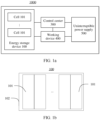
FIG. 1a is a schematic diagram of an application scenario of an energy storage device according to this application; -
FIG. 1b is a schematic diagram of a structure of an energy storage device according to an implementation of this application; -
FIG. 2 is a schematic diagram of a partial structure of a cell according to an implementation of this application; -
FIG. 3a is a sectional view of a cell cap according to an implementation of this application; -
FIG. 3b is an enlarged schematic diagram of a partial area of the cell cap shown inFIG. 3 a; -
FIG. 4 is a top view of a cell cap from which a reinforcement sheet is removed; and -
FIG. 5 is a schematic diagram of assembling a sealing ring and a pole part of a cell cap according to an implementation of this application. - For a pole of a cell cap, a positive pole is used as an example. The positive pole includes an aluminum block, an aluminum column, and an aluminum connection sheet, and is formed by sequentially welding the aluminum block, the aluminum column, and the aluminum connection sheet. A negative pole is formed by welding an aluminum block, a copper column, and a copper connection sheet. This structure is complicated in assembly and difficult in processing, and has high material and processing costs.
- Based on this, this application provides a cell cap and a related cell and energy storage device. The cell cap includes: a top cover, including a first surface and a second surface that are disposed opposite to each other, and further including a mounting through hole that passes through the first surface and the second surface; and a pole member, including a connection part and a pole part that are integrally disposed, where the connection part and the first surface are stacked, the pole part is disposed on the connection part in a protruding manner, and the pole part is fastened in and passes through the mounting through hole and is exposed from the second surface.
-
FIG. 1a is an application scenario applicable to an embodiment of this application. This application provides afunctional system 1000, including anenergy storage device 100, acontrol center 300, a workingdevice 400, and anuninterruptible power supply 500. In this embodiment, thefunctional system 1000 is a data center. Thecontrol center 300 and the workingdevice 400 are separately electrically connected to theuninterruptible power supply 500. Theuninterruptible power supply 500 is configured to supply power to thecontrol center 300 and the workingdevice 400. Theenergy storage device 100 is electrically connected to the workingdevice 400. As a supplementary energy source of thefunctional system 1000, theenergy storage device 100 supplies power to the workingdevice 400 and thecontrol center 300 when theuninterruptible power supply 500 of thefunctional system 1000 is faulty or in another case. Theenergy storage device 100, the workingdevice 400, and theuninterruptible power supply 500 are separately communicatively connected to thecontrol center 300. Thecontrol center 300 is configured to control and monitor the workingdevice 400, theenergy storage device 100, and theuninterruptible power supply 500. The workingdevice 400 includes a communication device, a lighting device, a data processing device, and the like. This is not limited herein. The uninterruptible power supply (UPS) 500 is configured to distribute power to theenergy storage device 100. - Refer to
FIG. 1b . Theenergy storage device 100 includes a plurality ofcells 101 that are configured to store electric energy and anenergy storage housing 102. The plurality ofcells 101 are connected in series and/or in parallel. The plurality ofcells 101 are accommodated in theenergy storage housing 102. Theenergy storage device 100 further includes another necessary or non-necessary structure or device, for example, a cooling apparatus. Details are not described herein. - It may be understood that the
functional system 1000 is not limited to the data center in this application, and theenergy storage device 100 may be further used in another field. For example, theenergy storage device 100 may be further used in a base station, an electric vehicle, a power station, and the like. Theenergy storage device 100 may alternatively be another energy storage device having an energy storage function, for example, a mobile phone, a tablet computer, or a notebook computer. When theenergy storage device 100 is a portable device like a mobile phone, a tablet computer, or a notebook computer, thecell 101 of theenergy storage device 100 supplies power to a load (for example, a mainboard, a video device, or an audio device) in theenergy storage device 100. - Refer to
FIG. 2 . Acell 101 includes ahousing 20 and acell cap 40. Thecell 101 further includes another necessary or non-necessary structure, for example, a cell. Details are not described herein. Thehousing 20 is configured to carry a device like the cell. - The
cell cap 40 includes atop cover 42 and apole member 44. Thetop cover 42 is fastened to and covers thehousing 20, and is configured to seal thehousing 20. Thepole member 44 is configured to be electrically connected to a workingdevice 400, so that thecell 101 supplies power to the workingdevice 400. - Refer to
FIG. 3a andFIG. 3b . Atopcover 42 includes afirst surface 422 and asecond surface 424 that are disposed opposite to each other. Thefirst surface 422 is disposed facing the inside of ahousing 20. Thesecond surface 424 is located on an outermost side of acell cap 40. Thetop cover 42 further includes a mounting throughhole 426 that passes through thefirst surface 422 and thesecond surface 424, and is configured to mount apole member 44. - The
pole member 44 includes apole piece 442, aplastic fastener 444, and asealing ring 446. Thepole piece 442 passes through the mounting throughhole 426. Theplastic fastener 444 is sleeved outside thepole piece 442, and is configured to fasten thepole piece 442 to thetop cover 42. The sealingring 446 is sealably connected between thepole piece 442 and an inner wall of the mounting throughhole 426. - The
pole piece 442 includes aconnection part 4422 and apole part 4424 that are integrally disposed. Theconnection part 4422 is fastened to thefirst surface 422. Thepole piece 442 may be formed in a manner of stamping or the like. Parameters such as a thickness of theconnection part 4422 and a height of thepole part 4424 may be selected based on a required current overload capability. A shape of theconnection part 4422 and a shape of thepole part 4424 are not limited in this application. Thepole part 4424 is disposed on theconnection part 4422 in a protruding manner. Thepole part 4424 passes through the mounting throughhole 426 and is exposed from thesecond surface 424. - According to the
cell cap 40 provided in this application, thepole piece 442 includes theconnection part 4422 and thepole part 4424 that are integrally disposed, that is, a pole and a connection sheet that are conventionally separately disposed are integrated. In this way, parts of thecell cap 40 are reduced, and a structure of thecell cap 40 is simplified. During assembly of acell 101, theconnection part 4422 and thepole part 4424 do not need to be connected together through a welding process. This reduces assembly steps of thecell cap 40, and reduces costs of thecell cap 40. When different structures or parts are assembled, an assembly error occurs. However, according to thecell cap 40 provided in this application, theconnection part 4422 and thepole part 4424 are integrally disposed, and assembly does not need to be performed. This reduces an assembly error of thecell cap 40, and improves assembly accuracy of thecell cap 40. - A first end of the
plastic fastener 444 passes through the mounting throughhole 426 and is fixedly connected to thetop cover 42. A second end of theplastic fastener 444 is exposed from thesecond surface 424. Theplastic fastener 444 is provided with a connection throughhole 4442. The connection throughhole 4442 passes through the first end and the second end of theplastic fastener 444. Thepole part 4424 passes through the connection throughhole 4442 and is fixedly connected to theplastic fastener 444. In this implementation, theplastic fastener 444 is fixedly connected to thepole part 4424 and thetop cover 42 in an injection molding manner. Theplastic fastener 444 is made of a material like polypropylene (polypropylene, PP), polyethylene terephthalate (polyethylene terephthalate, PET), or polystyrene sulfide (polyphenylene sulfide, PPS). Thepole part 4424 is fastened to the mounting throughhole 426 of thetop cover 42 by using theplastic fastener 444, so that use of a metal material is reduced, a production difficulty and production costs of thecell cap 40 are reduced, and a weight of thecell cap 40 is reduced. This facilitates lightweight development of thecell cap 40. - Refer to
FIG. 4 . Thepole piece 442 further includes a firstrotation stopping part 4426. The firstrotation stopping part 4426 is disposed on a peripheral surface of thepole part 4424. The peripheral surface of thepole part 4424 is an outer surface in a circumferential direction of thepole part 4424. The circumferential direction is perpendicular to an axial direction and a radial direction of thepole part 4424. Theplastic fastener 444 further includes a secondrotation stopping part 4446 disposed on an inner wall of the connection throughhole 4442. The firstrotation stopping part 4426 and the secondrotation stopping part 4446 are connected in a clamping manner, to reduce a possibility that thepole piece 442 rotates relative to thetop cover 42, so that thepole piece 442 can remain stable when electrically connected to another device, to improve use reliability of thecell 101. - In this implementation, the first
rotation stopping part 4426 extends in the axial direction of thepole part 4424. The firstrotation stopping part 4426 includes a protrusion disposed on the peripheral surface of thepole part 4424. The secondrotation stopping part 4446 includes a depression provided on the inner wall of the connection throughhole 4442. The protrusion is accommodated in the depression. - In another implementation of this application, the first
rotation stopping part 4426 is a depression provided on the peripheral surface of thepole part 4424, and the secondrotation stopping part 4446 is a protrusion disposed on the inner wall of the connection throughhole 4442. In other words, one of the firstrotation stopping part 4426 and the secondrotation stopping part 4446 is a protrusion, and the other of the firstrotation stopping part 4426 and the secondrotation stopping part 4446 is a depression. The protrusion is accommodated in the depression and is clamped to the depression. That is, one of the firstrotation stopping part 4426 and the secondrotation stopping part 4446 is a protrusion, and the other of the firstrotation stopping part 4426 and the secondrotation stopping part 4446 is a depression. The protrusion is accommodated in the depression and is clamped to the depression. - Refer to
FIG. 3a andFIG. 3b again. The sealingring 446 is accommodated in the mounting throughhole 426 and sleeved outside thepole part 4424. The sealingring 446 is fixedly connected to the first end of theplastic fastener 444. The sealingring 446 is sealably connected to the inner wall of the mounting throughhole 426, and thesealing ring 446 is sealably connected to an outer wall of thepole part 4424, so that thetop cover 42 is sealably connected to thepole piece 442, to improve sealing performance of thecell cap 40. An inner wall of the sealingring 446 is attached to the outer wall of thepole part 4424. An outer wall of the sealingring 446 is attached to the inner wall of the mounting throughhole 426. - In this implementation, the sealing
ring 446 includes afirst sealing part 4460 and asecond sealing part 4461 that are connected. Thefirst sealing part 4460 is attached to thefirst surface 422. Thesecond sealing part 4461 is fastened in and passes through the mounting throughhole 426. Thesecond sealing part 4461 is fixedly connected to the first end of theplastic fastener 444. Thefirst sealing part 4460 is attached to thefirst surface 422. This can effectively reduce a possibility that the sealingring 446 moves in an axial direction of the mounting throughhole 426, and therefore improve use reliability of thecell cap 40. - The
pole part 4424 is in a cylindrical shape. The inside of thepole part 4424 is of a hollow structure. Thepole member 44 further includes areinforcement sheet 448 that is configured to be electrically connected to a device like a workingdevice 400 outside thecell 101. Thepole part 4424 includes atop wall 4428 disposed at an end that is of thepole part 4424 and that is away from theconnection part 4422. Thereinforcement sheet 448 is fastened to thetop wall 4428 of thepole part 4424, and is configured to reinforce thepole piece 442. When thereinforcement sheet 448 is welded with another device, thereinforcement sheet 448 is further configured to reduce a possibility that thetop wall 4428 of thepole part 4424 is burnt or damaged due to a high welding temperature. Thereinforcement sheet 448 may be fastened to thetop wall 4428 of thepole part 4424 in a magnetic pulse welding manner or the like. A manner in which thereinforcement sheet 448 is fastened to thepole part 4424 is not limited in this application. In this implementation, thereinforcement sheet 448 is accommodated in the connection throughhole 4442, to improve connection stability between thereinforcement sheet 448 and thepole piece 442. - In this implementation, an area of the
top wall 4428 is less than an area of thereinforcement sheet 448, so that thepole part 4424 is isolated from the outside of thecell cap 40, and a possibility that a solder falls on thepole part 4424 when thereinforcement sheet 448 is welded with another device is reduced. In addition, thereinforcement sheet 448 can conduct impact on thepole part 4424 to theplastic fastener 444 for dispersion when thepole part 4424 is subject to an external force, for example, when thepole part 4424 is subject to an external force in the axial direction of the pole part 4424 (the axial direction is the same as a direction in which thereinforcement sheet 448 faces thepole part 4424 inFIG. 3b ). Because thereinforcement sheet 448 can conduct the impact on thepole part 4424 to theplastic fastener 444, thepole piece 442 is protected, and a service life of thepole piece 442 is increased. - In another implementation of this application, the area of the
top wall 4428 may alternatively be equal to the area of thereinforcement sheet 448, that is, the area of thetop wall 4428 is not greater than the area of thereinforcement sheet 448, and thereinforcement sheet 448 covers thetop wall 4428. In other words, in the axial direction of thepole part 4424, an orthographic projection of thetop wall 4428 on a projection plane is located in a region of an orthographic projection of thereinforcement sheet 448 on the projection plane, and the projection plane is perpendicular to the axial direction of thepole part 4424. - In another implementation of this application, the area of the
top wall 4428 may alternatively be greater than the area of thereinforcement sheet 448, provided that thereinforcement sheet 448 can reinforce thepole part 4424. - A ring-shaped
clamping slot 4447 is provided on the inner wall of the connection throughhole 4442, and thereinforcement sheet 448 is clamped in the ring-shapedclamping slot 4447, to improve connection stability between thereinforcement sheet 448 and theplastic fastener 444, and reduce a possibility that thereinforcement sheet 448 detaches from theplastic fastener 444. - In another implementation of this application, the
pole part 4424 may be in another shape, for example, a square column. The inside of thepole part 4424 may alternatively be solid. - In this implementation, the mounting through
hole 426 includes a first mounting through hole and a second mounting through hole. Thepole member 44 includes afirst pole member 401 and asecond pole member 403. Thefirst pole member 401 is disposed corresponding to the first mounting through hole. Thesecond pole member 403 is disposed corresponding to the second mounting through hole. Thefirst pole member 401 may be used as a positive pole, and thesecond pole member 403 may be used as a negative pole. Apole piece 442 in thefirst pole member 401 is made of aluminum. Apole piece 442 in thesecond pole member 403 is made of copper.Reinforcement sheets 448 in thefirst pole member 401 and thesecond pole member 403 both are made of aluminum. Thepole piece 442 of thesecond pole member 403 is made of copper, and thereinforcement sheet 448 is made of aluminum. When reinforcing thepole piece 442 of thesecond pole member 403, thereinforcement sheet 448 can effectively protect thepole piece 442 of thesecond pole member 403 from corrosion of an environment outside thecell cap 40. In another implementation of this application, thefirst pole member 401 may be used as a negative pole, and thesecond pole member 403 may be used as a positive pole. In another implementation of this application, a material of thepole piece 442 in thefirst pole member 401 is not limited to aluminum, a material of thepole piece 442 in thesecond pole member 403 is not limited to copper, and the material of thepole piece 442 in thefirst pole member 401 may be the same as or different from the material of thepole piece 442 in thesecond pole member 403. - The
cell cap 40 further includes afastening layer 47 that is configured to fixedly connect theconnection part 4422 to thefirst surface 422. Thefastening layer 47 covers thefirst surface 422. Corresponding to the mounting throughhole 426, thefastening layer 47 is provided with afastening hole 472 that passes through thefastening layer 47. Thepole part 4424 passes through thefastening hole 472. Thefastening layer 47 is located between thefirst surface 422 and theconnection part 4422. Thefastening layer 47 is fixedly connected to thefirst surface 422. Thefastening layer 47 is fixedly connected to theconnection part 4422. In this implementation, thefastening layer 47 is a plastic layer, and thefastening layer 47 may be formed between thefirst surface 422 and theconnection part 4422 through an injection molding process. During injection molding, a plastic material is placed between theconnection part 4422 and thefirst surface 422. After injection molding is completed, the plastic material forms thefastening layer 47. Thefastening layer 47 may be mounted on thefirst surface 422 by buckling, bonding, or the like. A material of thefastening layer 47 includes polypropylene (Polypropylene, PP), polyethylene terephthalate (Polyethylene terephthalate, PET), or the like. - In another implementation of this application, the second
rotation stopping part 4446 on theplastic fastener 444 may be omitted. Refer toFIG. 5 . The sealingring 446 further includes a secondrotation stopping part 4462 disposed on the inner wall of the sealingring 446. One of the firstrotation stopping part 4426 on thepole part 4424 and the secondrotation stopping part 4462 on thesealing ring 446 is a protrusion, and the other of the firstrotation stopping part 4426 and the secondrotation stopping part 4462 is a depression. The protrusion is accommodated in the depression and is clamped to the depression. - In another implementation of this application, a second rotation stopping part is disposed on each of the
plastic fastener 444 and thesealing ring 446. - In another implementation of this application, the
plastic fastener 444 may be omitted, and thepole piece 442 is directly fastened to thetop cover 42 in another manner, for example, in a riveting manner. A manner in which thepole piece 442 is fastened to thetop cover 42 is not limited in this application. - Expressions such as "include" and "may include" that may be used in this application indicate existence of the disclosed function, operation, or constituent element, and do not limit one or more additional functions, operations, and constituent elements. In this application, terms such as "include" and/or "have" may be construed as indicating a specific characteristic, quantity, operation, constituent element, or component, or a combination thereof, but cannot be construed as excluding existence or a possibility of addition of one or more other characteristics, quantities, operations, constituent elements, or components, or combinations thereof.
- In addition, in this application, the expression "and/or" includes any and all combinations of words listed in association. For example, the expression "A and/or B" may include A, may include B, or may include both A and B.
- In this application, expressions including ordinal numbers such as "first" and "second" may modify elements. However, such elements are not limited by the expressions. For example, the expressions do not limit the order and/or importance of the elements. The expression is used only to distinguish one element from another. For example, first user equipment and second user equipment indicate different user equipment, although both the first user equipment and the second user equipment are user equipment. Similarly, without departing from the scope of this application, a first element may be referred to as a second element, and similarly, a second element may also be referred to as a first element.
- When a component "connects" or "connects to" another component, the component not only directly connects or connects to the another component, but there may be another component between the component and the another component. In addition, when a component "directly connects" or "directly connects to" another component, there is no component between the components.
- The foregoing descriptions are only specific implementations of this application, but the protection scope of this application is not limited thereto. Any variation or replacement readily figured out by a person skilled in the art within the technical scope disclosed in this application shall fall within the protection scope of this application. Therefore, the protection scope of this application shall be subject to the protection scope of the claims.
Claims (14)
- A cell cap, comprising:a top cover, comprising a first surface and a second surface that are disposed opposite to each other, and further comprising a mounting through hole that passes through the first surface and the second surface; anda pole member, comprising a connection part and a pole part that are integrally disposed, wherein the connection part is fastened to the first surface, the pole part is disposed on the connection part in a protruding manner, and the pole part is fastened in and passes through the mounting through hole and is exposed from the second surface.
- The cell cap according to claim 1, wherein the pole member comprises a pole piece and a plastic fastener, the connection part and the pole part both are disposed on the pole piece, the plastic fastener is provided with a connection through hole, a first end of the plastic fastener passes through the mounting through hole and is fixedly connected to the top cover, a second end of the plastic fastener is exposed from the second surface, and the pole part passes through the connection through hole and is fixedly connected to the plastic fastener.
- The cell cap according to claim 2, wherein the pole piece further comprises a first rotation stopping part, and the first rotation stopping part is disposed on a peripheral surface of the pole part; the plastic fastener further comprises a second rotation stopping part disposed on an inner wall of the connection through hole; one of the first rotation stopping part and the second rotation stopping part is a protrusion, and the other is a depression; and the protrusion is accommodated in the depression and is clamped to the depression.
- The cell cap according to claim 2, wherein the pole member further comprises a sealing ring, the sealing ring passes through the mounting through hole and is sleeved outside the pole part, the sealing ring is sealably connected to a peripheral surface of the pole part, the sealing ring is sealably connected to an inner wall of the mounting through hole, and the sealing ring is fixedly connected to the first end of the plastic fastener.
- The cell cap according to claim 4, wherein the pole piece further comprises a first rotation stopping part, and the first rotation stopping part is disposed on the peripheral surface of the pole part; the sealing ring further comprises a second rotation stopping part disposed on an inner wall of the sealing ring; one of the first rotation stopping part and the second rotation stopping part is a protrusion, and the other is a depression; and the protrusion is accommodated in the depression and is clamped to the depression.
- The cell cap according to claim 4, wherein the sealing ring comprises a first sealing part and a second sealing part that are connected, the first sealing part is attached to the first surface, the second sealing part is fastened in and passes through the mounting through hole, and the second sealing part is fixedly connected to the first end of the plastic fastener.
- The cell cap according to claim 2, wherein the pole member further comprises a reinforcement sheet, the pole part comprises a top wall disposed at an end that is of the pole part and that is away from the connection part, and the reinforcement sheet is fastened to the top wall.
- The cell cap according to claim 7, wherein the reinforcement sheet is accommodated in the connection through hole.
- The cell cap according to claim 8, wherein an area of the top wall is not greater than an area of the reinforcement sheet.
- The cell cap according to claim 8, wherein a ring-shaped clamping slot is provided on an inner wall of the connection through hole, and the reinforcement sheet is clamped in the ring-shaped clamping slot.
- The cell cap according to claim 9, wherein the mounting through hole comprises a first mounting through hole and a second mounting through hole, the pole member comprises a first pole member and a second pole member, the first pole member is disposed corresponding to the first mounting through hole, the second pole member is disposed corresponding to the second mounting through hole, a pole piece in the first pole member is made of aluminum, a pole piece in the second pole member is made of copper, and reinforcement sheets in the first pole member and the second pole member both are made of copper.
- The cell cap according to any one of claims 1 to 11, wherein the cell cap further comprises a fastening layer covering the first surface, the fastening layer is provided with a fastening hole corresponding to the mounting through hole, the connection part is fixedly connected to a side that is of the fastening layer and that is away from the first surface, and the pole part passes through the fastening hole.
- A cell, comprising a housing and the cell cap according to any one of claims 1 to 12, wherein a top cover is fastened to and covers the housing, and a connection part is accommodated in the housing.
- An energy storage device, comprising an energy storage housing and a plurality of cells connected in series and/or in parallel according to claim 13, wherein the plurality of cells connected in series and/or in parallel are accommodated in the energy storage housing.
Applications Claiming Priority (2)
| Application Number | Priority Date | Filing Date | Title |
|---|---|---|---|
| CN202220245244.6U CN217544751U (en) | 2022-01-29 | 2022-01-29 | Battery cover plate, battery and energy storage equipment |
| PCT/CN2023/072624 WO2023143250A1 (en) | 2022-01-29 | 2023-01-17 | Battery cover plate, battery, and energy storage device |
Publications (2)
| Publication Number | Publication Date |
|---|---|
| EP4386948A1 true EP4386948A1 (en) | 2024-06-19 |
| EP4386948A4 EP4386948A4 (en) | 2025-07-30 |
Family
ID=83425864
Family Applications (1)
| Application Number | Title | Priority Date | Filing Date |
|---|---|---|---|
| EP23746132.2A Pending EP4386948A4 (en) | 2022-01-29 | 2023-01-17 | BATTERY COVER PLATE, BATTERY AND ENERGY STORAGE DEVICE |
Country Status (3)
| Country | Link |
|---|---|
| EP (1) | EP4386948A4 (en) |
| CN (1) | CN217544751U (en) |
| WO (1) | WO2023143250A1 (en) |
Families Citing this family (2)
| Publication number | Priority date | Publication date | Assignee | Title |
|---|---|---|---|---|
| CN217544751U (en) * | 2022-01-29 | 2022-10-04 | 华为数字能源技术有限公司 | Battery cover plate, battery and energy storage equipment |
| CN117559092A (en) * | 2023-11-14 | 2024-02-13 | 蜂巢能源科技股份有限公司 | Cover components and batteries |
Family Cites Families (5)
| Publication number | Priority date | Publication date | Assignee | Title |
|---|---|---|---|---|
| CN205921025U (en) * | 2016-07-20 | 2017-02-01 | 深圳塔菲尔新能源科技有限公司 | Connection structure of compound utmost point post |
| CN110379953A (en) * | 2019-07-31 | 2019-10-25 | 江苏塔菲尔新能源科技股份有限公司 | A kind of assembling structure and its assembly method of battery cap |
| CN110429212B (en) * | 2019-07-31 | 2024-03-19 | 江苏正力新能电池技术有限公司 | Battery top cover assembly structure and assembly method |
| CN112820988A (en) * | 2021-01-20 | 2021-05-18 | 东莞塔菲尔新能源科技有限公司 | Power battery top cover structure and power battery |
| CN217544751U (en) * | 2022-01-29 | 2022-10-04 | 华为数字能源技术有限公司 | Battery cover plate, battery and energy storage equipment |
-
2022
- 2022-01-29 CN CN202220245244.6U patent/CN217544751U/en active Active
-
2023
- 2023-01-17 EP EP23746132.2A patent/EP4386948A4/en active Pending
- 2023-01-17 WO PCT/CN2023/072624 patent/WO2023143250A1/en not_active Ceased
Also Published As
| Publication number | Publication date |
|---|---|
| CN217544751U (en) | 2022-10-04 |
| EP4386948A4 (en) | 2025-07-30 |
| WO2023143250A1 (en) | 2023-08-03 |
Similar Documents
| Publication | Publication Date | Title |
|---|---|---|
| EP4386948A1 (en) | Battery cover plate, battery, and energy storage device | |
| EP1599915B1 (en) | Lithium ion batteries | |
| EP2056374B1 (en) | Battery pack | |
| EP3297059A1 (en) | Battery module and battery pack including same | |
| EP3038188B1 (en) | Battery pack comprising electrically insulating member | |
| WO2022213728A1 (en) | Battery and electrical device | |
| US12051828B2 (en) | Battery pack and device including the same | |
| US8865343B2 (en) | PCM assembly and prismatic type secondary battery using the same | |
| KR102912908B1 (en) | Battery cells, batteries, electrical devices, methods and equipment for manufacturing battery cells | |
| EP4462578A1 (en) | Explosion-proof valve patch for battery, end cover assembly, battery, and electric device | |
| EP4404352A1 (en) | Battery box, battery and power consuming device | |
| CN105990544A (en) | Battery pack | |
| US20250266488A1 (en) | Battery and electronic apparatus | |
| EP2744016B1 (en) | Novel structure for a battery pack | |
| JP4989920B2 (en) | Battery pack | |
| JP2012079535A (en) | Battery pack | |
| JP2000277072A (en) | Battery pack for small electrical equipment | |
| US20230347755A1 (en) | Battery module and battery pack including the same | |
| EP4181278A1 (en) | Battery module and battery pack including same | |
| EP4095990A1 (en) | Battery cell, battery pack, and electronic device | |
| US20250070419A1 (en) | Electrode lead-out member, cover assembly, secondary battery and electronic apparatus | |
| EP4307449A1 (en) | Battery housing structure and manufacturing method therefor, battery, and electric device | |
| EP4672459A1 (en) | BATTERY CELL, BATTERY, ELECTRICAL DEVICE AND CARRIER | |
| KR101514426B1 (en) | Connector, battery pack having the same and assembling method thereof | |
| CN222483474U (en) | Battery cells, batteries and electrical devices |
Legal Events
| Date | Code | Title | Description |
|---|---|---|---|
| STAA | Information on the status of an ep patent application or granted ep patent |
Free format text: STATUS: THE INTERNATIONAL PUBLICATION HAS BEEN MADE |
|
| PUAI | Public reference made under article 153(3) epc to a published international application that has entered the european phase |
Free format text: ORIGINAL CODE: 0009012 |
|
| STAA | Information on the status of an ep patent application or granted ep patent |
Free format text: STATUS: REQUEST FOR EXAMINATION WAS MADE |
|
| 17P | Request for examination filed |
Effective date: 20240312 |
|
| AK | Designated contracting states |
Kind code of ref document: A1 Designated state(s): AL AT BE BG CH CY CZ DE DK EE ES FI FR GB GR HR HU IE IS IT LI LT LU LV MC ME MK MT NL NO PL PT RO RS SE SI SK SM TR |
|
| DAV | Request for validation of the european patent (deleted) | ||
| DAX | Request for extension of the european patent (deleted) | ||
| A4 | Supplementary search report drawn up and despatched |
Effective date: 20250630 |
|
| RIC1 | Information provided on ipc code assigned before grant |
Ipc: H01M 50/147 20210101AFI20250624BHEP Ipc: H01M 50/552 20210101ALI20250624BHEP Ipc: H01M 10/0525 20100101ALI20250624BHEP Ipc: H01M 50/148 20210101ALI20250624BHEP Ipc: H01M 50/172 20210101ALI20250624BHEP Ipc: H01M 50/188 20210101ALI20250624BHEP Ipc: H01M 50/543 20210101ALI20250624BHEP Ipc: H01M 50/184 20210101ALI20250624BHEP |