EP4386939A1 - Box body, battery, electric device, and device for preparing battery - Google Patents
Box body, battery, electric device, and device for preparing battery Download PDFInfo
- Publication number
- EP4386939A1 EP4386939A1 EP22928291.8A EP22928291A EP4386939A1 EP 4386939 A1 EP4386939 A1 EP 4386939A1 EP 22928291 A EP22928291 A EP 22928291A EP 4386939 A1 EP4386939 A1 EP 4386939A1
- Authority
- EP
- European Patent Office
- Prior art keywords
- snap
- fitting portion
- thermal management
- management component
- protective plate
- Prior art date
- Legal status (The legal status is an assumption and is not a legal conclusion. Google has not performed a legal analysis and makes no representation as to the accuracy of the status listed.)
- Pending
Links
Images



Classifications
-
- H—ELECTRICITY
- H01—ELECTRIC ELEMENTS
- H01M—PROCESSES OR MEANS, e.g. BATTERIES, FOR THE DIRECT CONVERSION OF CHEMICAL ENERGY INTO ELECTRICAL ENERGY
- H01M10/00—Secondary cells; Manufacture thereof
- H01M10/60—Heating or cooling; Temperature control
- H01M10/65—Means for temperature control structurally associated with the cells
- H01M10/655—Solid structures for heat exchange or heat conduction
- H01M10/6556—Solid parts with flow channel passages or pipes for heat exchange
-
- F—MECHANICAL ENGINEERING; LIGHTING; HEATING; WEAPONS; BLASTING
- F28—HEAT EXCHANGE IN GENERAL
- F28D—HEAT-EXCHANGE APPARATUS, NOT PROVIDED FOR IN ANOTHER SUBCLASS, IN WHICH THE HEAT-EXCHANGE MEDIA DO NOT COME INTO DIRECT CONTACT
- F28D1/00—Heat-exchange apparatus having stationary conduit assemblies for one heat-exchange medium only, the media being in contact with different sides of the conduit wall, in which the other heat-exchange medium is a large body of fluid, e.g. domestic or motor car radiators
- F28D1/02—Heat-exchange apparatus having stationary conduit assemblies for one heat-exchange medium only, the media being in contact with different sides of the conduit wall, in which the other heat-exchange medium is a large body of fluid, e.g. domestic or motor car radiators with heat-exchange conduits immersed in the body of fluid
- F28D1/04—Heat-exchange apparatus having stationary conduit assemblies for one heat-exchange medium only, the media being in contact with different sides of the conduit wall, in which the other heat-exchange medium is a large body of fluid, e.g. domestic or motor car radiators with heat-exchange conduits immersed in the body of fluid with tubular conduits
- F28D1/053—Heat-exchange apparatus having stationary conduit assemblies for one heat-exchange medium only, the media being in contact with different sides of the conduit wall, in which the other heat-exchange medium is a large body of fluid, e.g. domestic or motor car radiators with heat-exchange conduits immersed in the body of fluid with tubular conduits the conduits being straight
- F28D1/0535—Heat-exchange apparatus having stationary conduit assemblies for one heat-exchange medium only, the media being in contact with different sides of the conduit wall, in which the other heat-exchange medium is a large body of fluid, e.g. domestic or motor car radiators with heat-exchange conduits immersed in the body of fluid with tubular conduits the conduits being straight the conduits having a non-circular cross-section
- F28D1/05366—Assemblies of conduits connected to common headers, e.g. core type radiators
- F28D1/05383—Assemblies of conduits connected to common headers, e.g. core type radiators with multiple rows of conduits or with multi-channel conduits
-
- F—MECHANICAL ENGINEERING; LIGHTING; HEATING; WEAPONS; BLASTING
- F28—HEAT EXCHANGE IN GENERAL
- F28F—DETAILS OF HEAT-EXCHANGE AND HEAT-TRANSFER APPARATUS, OF GENERAL APPLICATION
- F28F9/00—Casings; Header boxes; Auxiliary supports for elements; Auxiliary members within casings
- F28F9/007—Auxiliary supports for elements
-
- H—ELECTRICITY
- H01—ELECTRIC ELEMENTS
- H01M—PROCESSES OR MEANS, e.g. BATTERIES, FOR THE DIRECT CONVERSION OF CHEMICAL ENERGY INTO ELECTRICAL ENERGY
- H01M10/00—Secondary cells; Manufacture thereof
- H01M10/60—Heating or cooling; Temperature control
- H01M10/61—Types of temperature control
- H01M10/613—Cooling or keeping cold
-
- H—ELECTRICITY
- H01—ELECTRIC ELEMENTS
- H01M—PROCESSES OR MEANS, e.g. BATTERIES, FOR THE DIRECT CONVERSION OF CHEMICAL ENERGY INTO ELECTRICAL ENERGY
- H01M10/00—Secondary cells; Manufacture thereof
- H01M10/60—Heating or cooling; Temperature control
- H01M10/61—Types of temperature control
- H01M10/615—Heating or keeping warm
-
- H—ELECTRICITY
- H01—ELECTRIC ELEMENTS
- H01M—PROCESSES OR MEANS, e.g. BATTERIES, FOR THE DIRECT CONVERSION OF CHEMICAL ENERGY INTO ELECTRICAL ENERGY
- H01M10/00—Secondary cells; Manufacture thereof
- H01M10/60—Heating or cooling; Temperature control
- H01M10/62—Heating or cooling; Temperature control specially adapted for specific applications
- H01M10/625—Vehicles
-
- H—ELECTRICITY
- H01—ELECTRIC ELEMENTS
- H01M—PROCESSES OR MEANS, e.g. BATTERIES, FOR THE DIRECT CONVERSION OF CHEMICAL ENERGY INTO ELECTRICAL ENERGY
- H01M10/00—Secondary cells; Manufacture thereof
- H01M10/60—Heating or cooling; Temperature control
- H01M10/65—Means for temperature control structurally associated with the cells
- H01M10/656—Means for temperature control structurally associated with the cells characterised by the type of heat-exchange fluid
- H01M10/6561—Gases
-
- H—ELECTRICITY
- H01—ELECTRIC ELEMENTS
- H01M—PROCESSES OR MEANS, e.g. BATTERIES, FOR THE DIRECT CONVERSION OF CHEMICAL ENERGY INTO ELECTRICAL ENERGY
- H01M10/00—Secondary cells; Manufacture thereof
- H01M10/60—Heating or cooling; Temperature control
- H01M10/65—Means for temperature control structurally associated with the cells
- H01M10/656—Means for temperature control structurally associated with the cells characterised by the type of heat-exchange fluid
- H01M10/6567—Liquids
- H01M10/6568—Liquids characterised by flow circuits, e.g. loops, located externally to the cells or cell casings
-
- H—ELECTRICITY
- H01—ELECTRIC ELEMENTS
- H01M—PROCESSES OR MEANS, e.g. BATTERIES, FOR THE DIRECT CONVERSION OF CHEMICAL ENERGY INTO ELECTRICAL ENERGY
- H01M10/00—Secondary cells; Manufacture thereof
- H01M10/60—Heating or cooling; Temperature control
- H01M10/65—Means for temperature control structurally associated with the cells
- H01M10/658—Means for temperature control structurally associated with the cells by thermal insulation or shielding
-
- H—ELECTRICITY
- H01—ELECTRIC ELEMENTS
- H01M—PROCESSES OR MEANS, e.g. BATTERIES, FOR THE DIRECT CONVERSION OF CHEMICAL ENERGY INTO ELECTRICAL ENERGY
- H01M50/00—Constructional details or processes of manufacture of the non-active parts of electrochemical cells other than fuel cells, e.g. hybrid cells
- H01M50/20—Mountings; Secondary casings or frames; Racks, modules or packs; Suspension devices; Shock absorbers; Transport or carrying devices; Holders
- H01M50/233—Mountings; Secondary casings or frames; Racks, modules or packs; Suspension devices; Shock absorbers; Transport or carrying devices; Holders characterised by physical properties of casings or racks, e.g. dimensions
- H01M50/242—Mountings; Secondary casings or frames; Racks, modules or packs; Suspension devices; Shock absorbers; Transport or carrying devices; Holders characterised by physical properties of casings or racks, e.g. dimensions adapted for protecting batteries against vibrations, collision impact or swelling
-
- H—ELECTRICITY
- H01—ELECTRIC ELEMENTS
- H01M—PROCESSES OR MEANS, e.g. BATTERIES, FOR THE DIRECT CONVERSION OF CHEMICAL ENERGY INTO ELECTRICAL ENERGY
- H01M50/00—Constructional details or processes of manufacture of the non-active parts of electrochemical cells other than fuel cells, e.g. hybrid cells
- H01M50/20—Mountings; Secondary casings or frames; Racks, modules or packs; Suspension devices; Shock absorbers; Transport or carrying devices; Holders
- H01M50/249—Mountings; Secondary casings or frames; Racks, modules or packs; Suspension devices; Shock absorbers; Transport or carrying devices; Holders specially adapted for aircraft or vehicles, e.g. cars or trains
-
- H—ELECTRICITY
- H01—ELECTRIC ELEMENTS
- H01M—PROCESSES OR MEANS, e.g. BATTERIES, FOR THE DIRECT CONVERSION OF CHEMICAL ENERGY INTO ELECTRICAL ENERGY
- H01M50/00—Constructional details or processes of manufacture of the non-active parts of electrochemical cells other than fuel cells, e.g. hybrid cells
- H01M50/20—Mountings; Secondary casings or frames; Racks, modules or packs; Suspension devices; Shock absorbers; Transport or carrying devices; Holders
- H01M50/262—Mountings; Secondary casings or frames; Racks, modules or packs; Suspension devices; Shock absorbers; Transport or carrying devices; Holders with fastening means, e.g. locks
-
- F—MECHANICAL ENGINEERING; LIGHTING; HEATING; WEAPONS; BLASTING
- F28—HEAT EXCHANGE IN GENERAL
- F28F—DETAILS OF HEAT-EXCHANGE AND HEAT-TRANSFER APPARATUS, OF GENERAL APPLICATION
- F28F2275/00—Fastening; Joining
- F28F2275/08—Fastening; Joining by clamping or clipping
- F28F2275/085—Fastening; Joining by clamping or clipping with snap connection
-
- H—ELECTRICITY
- H01—ELECTRIC ELEMENTS
- H01M—PROCESSES OR MEANS, e.g. BATTERIES, FOR THE DIRECT CONVERSION OF CHEMICAL ENERGY INTO ELECTRICAL ENERGY
- H01M2220/00—Batteries for particular applications
- H01M2220/20—Batteries in motive systems, e.g. vehicle, ship, plane
-
- Y—GENERAL TAGGING OF NEW TECHNOLOGICAL DEVELOPMENTS; GENERAL TAGGING OF CROSS-SECTIONAL TECHNOLOGIES SPANNING OVER SEVERAL SECTIONS OF THE IPC; TECHNICAL SUBJECTS COVERED BY FORMER USPC CROSS-REFERENCE ART COLLECTIONS [XRACs] AND DIGESTS
- Y02—TECHNOLOGIES OR APPLICATIONS FOR MITIGATION OR ADAPTATION AGAINST CLIMATE CHANGE
- Y02E—REDUCTION OF GREENHOUSE GAS [GHG] EMISSIONS, RELATED TO ENERGY GENERATION, TRANSMISSION OR DISTRIBUTION
- Y02E60/00—Enabling technologies; Technologies with a potential or indirect contribution to GHG emissions mitigation
- Y02E60/10—Energy storage using batteries
Definitions
- This application relates to the field of battery technologies, and more specifically, to a box, a battery, an electric apparatus, and an apparatus for manufacturing battery.
- this application provides a box, a battery, an electric apparatus, and an apparatus for manufacturing battery, aiming to improve safety performance of batteries.
- a box for accommodating a battery cell, characterized by including: a thermal management component, where the thermal management component is configured to regulate temperature of the battery cell; and a protective plate, disposed at a side of the thermal management component away from the battery cell and configured to protect the thermal management component.
- the thermal management component is provided with a first snap-fitting portion
- the protective plate is provided with a second snap-fitting portion. The first snap-fitting portion and the second snap-fitting portion are snap-fitted to connect the thermal management component and the protective plate.
- the thermal management component is provided with the first snap-fitting portion
- the protective plate is provided with the second snap-fitting portion
- the first snap-fitting portion and the second snap-fitting portion are snap-fitted, so that the thermal management component and the protective plate can be quickly fitted together, achieving stability and reliability, thereby improving overall mechanical structural performance of the box.
- the thermal management component and the protective plate can be fitted together, the assembly efficiency of the box can be improved.
- the snap fitting between the thermal management component and the protective plate can also prevent collision, thereby improving the safety performance of a battery.
- the thermal management component includes multiple groups of fluid pipelines, where each of the multiple groups of fluid pipelines is provided with a first snap-fitting portion; the protective plate is provided with a second snap-fitting portion corresponding to each group of fluid pipelines; and each group of fluid pipelines and the protective plate are snap-fitted via the first snap-fitting portion and the second snap-fitting portion.
- the thermal management component includes multiple groups of fluid pipelines, and each group of fluid pipelines and the protective plate can be snap-fitted via the first snap-fitting portion and the second snap-fitting portion, thereby further improving the overall mechanical structural performance of the box.
- first snap-fitting portion and the second snap-fitting portion extend along the same direction as the fluid pipelines extend.
- each group of fluid pipelines is provided with one pair of first snap-fitting portions respectively located at two sides of a corresponding group of fluid pipelines.
- the thermal management component further includes two flow gathering pipes, where two ends of each group of fluid pipelines are respectively connected to the two flow gathering pipes, and the multiple groups of fluid pipelines are spaced apart along an extension direction of the flow gathering pipes.
- the flow gathering pipes can not only connect the multiple groups of fluid pipelines, but also allow for convenient management for a fluid flowing into or out of the fluid pipelines.
- one of the first snap-fitting portion and the second snap-fitting portion is a slot structure
- the other one of the first snap-fitting portion and the second snap-fitting portion is a snap structure, where the snap structure is inserted into the slot structure to implement snap fitting between the first snap-fitting portion and the second snap-fitting portion.
- the first snap-fitting portion and the second snap-fitting portion are snap-fitted via the snap structure and the slot structure, improving the reliability of the connection between the thermal management component and the protective plate.
- the first snap-fitting portion extends toward the protective plate from a first surface of the thermal management component
- the second snap-fitting portion extends toward the thermal management component from a second surface of the protective plate.
- the first surface and the second surface are opposite each other.
- the first snap-fitting portion and the second snap-fitting portion are snap-fitted between the first surface and the second surface to connect the thermal management component and the protective plate.
- the first snap-fitting portion is a slot structure.
- the slot structure includes a first slot wall and a second slot wall perpendicular to each other, and the first slot wall is perpendicular to the first surface.
- the second snap-fitting portion is a snap structure.
- the snap structure includes a snap body and a bent portion connected to each other, and the snap body is perpendicular to the second surface. The bent portion abuts against the second slot wall and is limited between the first slot wall and the snap body.
- the first snap-fitting portion is a slot structure
- the second snap-fitting portion is a snap structure
- the bent portion of the snap structure abuts against the second slot wall of the slot structure and is limited between the first slot wall of the slot structure and the snap body of the snap structure. Therefore, when the protective plate is a bottom protective plate, structural stiffness of the box in a height direction can be enhanced, and a spatial size in the height direction is also increased to provide a buffer space, thereby improving a collision prevention effect, and also achieving adaptability to various processing implementation manners.
- the first snap-fitting portion is a slot structure
- the second snap-fitting portion is a snap structure, where an opening of the slot structure faces the second surface, and in a cross section along an extension direction of the slot structure, size of the opening of the slot structure is smaller than a maximum size of the slot structure and a maximum size of the snap structure, such that the snap structure is able to be inserted into the slot structure and able to limit movement of the protective plate along a direction perpendicular to the first surface with respect to the thermal management component.
- the first snap-fitting portion is a slot structure
- the second snap-fitting portion is a snap structure
- the size of the opening of the slot structure is smaller than the maximum size of the slot structure and the maximum size of the snap structure, such that the snap structure is able to be inserted into the slot structure and able to limit movement of the protective plate along a direction perpendicular to the first surface with respect to the thermal management component. Therefore, when the protective plate is a bottom protective plate, structural stiffness of the box in a height direction can be enhanced, and a spatial size in the height direction is also increased to provide a buffer space, thereby improving a collision prevention effect.
- the cross section of the slot structure along the extension direction of the slot structure is in a first arc shape, and distance between two end points of the first arc shape is less than diameter of the arc shape.
- a cross section of the snap structure along the first direction is in a second arc shape, and diameter of the second arc shape is less than the diameter of the first arc shape and greater than the distance between the two end points of the first arc shape.
- the first snap-fitting portion extends along a direction parallel to the first surface of the thermal management component from a side surface of the thermal management component
- the second snap-fitting portion extends from the second surface of the protective plate along a direction leaving the second surface and is snap-fitted with the first snap-fitting portion on the side surface of the thermal management component, so as to connect the thermal management component and the protective plate, where the first surface and the second surface are opposite each other.
- the first snap-fitting portion is a snap structure
- the second snap-fitting portion is a slot structure
- the second snap-fitting portion is snap-fitted with the first snap-fitting portion on the side surface of the thermal management component. Therefore, when the protective plate is a bottom protective plate, space of the box in a height direction can be saved, thereby improving space utilization.
- the first snap-fitting portion is a snap structure
- the second snap-fitting portion is a slot structure.
- the snap structure includes a third surface and a fourth surface parallel to each other. The third surface is farther away from the second surface than the fourth surface, the fourth surface is an extension surface of the first surface, and in a direction perpendicular to the first surface, size of the snap structure is smaller than size of the thermal management component.
- the slot structure includes a third slot wall and a fourth slot wall perpendicular to each other, the third slot wall is perpendicular to the second surface, and the fourth slot wall abuts against the third surface and is limited between the third slot wall and the side surface of the thermal management component.
- the box further includes insulating foam sandwiched between the protective plate and the thermal management component.
- the insulating foam can maintain temperature of the thermal management component, thereby better improving thermal management performance.
- the box further includes a frame perpendicular to the protective plate and disposed around the battery cell, where the frame is fixedly connected to the protective plate.
- the thermal management component and the protective plate are snap-fitted, and the protective plate and the frame are fixedly connected, so that the thermal management component can be limited in all directions, thereby improving the overall mechanical structural performance of the box.
- the box further includes a sealing structure disposed between the frame and the protective plate.
- the sealing structure disposed between the protective plate and the frame can improve airtightness of the box, thereby improving the safety of the battery.
- the sealing structure includes a sealing gasket and/or a sealing adhesive.
- the frame is fixedly connected to the protective plate through riveting of a flow drill screw, friction stir welding, or a bolt.
- a battery including multiple battery cells and the box according to the first aspect or any one of the possible embodiments, where the multiple battery cells are accommodated in the box.
- an electric apparatus including the battery according to the second aspect, where the battery is configured to provide electrical energy for the electric apparatus.
- an apparatus for manufacturing battery including: a providing module, configured to provide a battery cell and provide a box for accommodating the battery cell.
- the box includes: a thermal management component, where the thermal management component is configured to regulate temperature of the battery cell; and a protective plate, disposed at a side of the thermal management component away from the battery cell and configured to protect the thermal management component.
- the thermal management component is provided with a first snap-fitting portion
- the protective plate is provided with a second snap-fitting portion. The first snap-fitting portion and the second snap-fitting portion are snap-fitted to connect the thermal management component and the protective plate.
- connection should be understood in their general senses. For example, they may refer to a fixed connection, a detachable connection, or an integral connection, and may refer to a direct connection, an indirect connection via an intermediate medium, or an internal communication between two elements. Persons of ordinary skill in the art can understand specific meanings of these terms in this application as appropriate to specific situations.
- multiple means more than two (inclusive).
- multiple groups means more than two (inclusive) groups
- multiple pieces means more than two (inclusive) pieces.
- the battery cell may be a lithium-ion secondary battery, a lithium-ion primary battery, a lithium-sulfur battery, a sodium-lithium-ion battery, a sodium-ion battery, a magnesium-ion battery, or the like. This is not limited in the embodiments of this application.
- the battery cell may be cylindrical, flat, cuboid, or of other shapes. This is not limited in the embodiments of this application either. Battery cells are typically divided into three types by packaging method: cylindrical cell, prismatic cell, and pouch cell. This is not limited in the embodiments of this application either.
- the battery mentioned in the embodiments of this application is a single physical module that includes one or more battery cells for providing a higher voltage and capacity.
- the battery mentioned in this application may include a battery module, a battery pack, or the like.
- a battery typically includes a box configured to enclose one or more battery cells. The box can prevent liquids or other foreign matter from affecting charging or discharging of the battery cell.
- the thermal management component and a bottom protective plate are separately assembled, to be specific, the bottom protective plate is firstly assembled onto a frame of the box, then the thermal management component is placed on the bottom protective plate, and the thermal management component and the bottom protective plate are not fixed or fixed through adhesion, resulting in insufficient overall stiffness between the thermal management component and the bottom protective plate.
- the thermal management component and the bottom protective plate may cause damage to the battery, thus affecting the safety of the battery.
- the embodiments of this application provide a technical solution, in which the thermal management component and the protective plate are fixed through snap fitting, improving the overall mechanical structural performance of the box.
- the snap fitting between the thermal management component and the protective plate can also prevent collision, thereby improving the safety performance of a battery.
- batteries for example, mobile phones, portable devices, notebook computers, electric bicycles, electric toys, electric tools, electric vehicles, ships, and spacecrafts.
- spacecrafts include airplanes, rockets, space shuttles, and spaceships.
- FIG. 1 is a schematic structural diagram of a vehicle 1 according to an embodiment of this application.
- the vehicle 1 may be a fossil fuel vehicle, a natural-gas vehicle, or a new energy vehicle, where the new energy vehicle may be a battery electric vehicle, a hybrid electric vehicle, a range-extended vehicle, or the like.
- the vehicle 1 may be provided with a motor 80, a controller 60, and a battery 100 inside, where the controller 60 is configured to control the battery 100 to supply power to the motor 80.
- the battery 100 may be disposed at the bottom, front, or rear of the vehicle 1.
- the battery 100 may be configured to supply power to the vehicle 1.
- the battery 100 may be used as an operational power source for the vehicle 1 for use in a circuit system of the vehicle 1, for example, to satisfy power needs of start, navigation, and running of the vehicle 1.
- the battery 100 may be used not only as the operational power source for the vehicle 1, but also as a driving power source for the vehicle 1, replacing or partially replacing fossil fuel or natural gas to provide driving traction for the vehicle 1.
- the battery may include multiple battery cells, and the multiple battery cells may be connected in series, parallel, or series-parallel, where being connected in series-parallel means a combination of series and parallel connections.
- the battery may also be referred to as a battery pack.
- multiple battery cells may be connected in series, parallel, or series-parallel to form a battery module first, and then multiple battery modules are connected in series, parallel, or series-parallel to form a battery.
- the multiple battery cells may be directly combined into a battery, or may first be combined into battery modules that are then combined into a battery.
- FIG. 2 is a schematic structural diagram of a battery 100 according to an embodiment of this application.
- the battery 100 may include multiple battery cells 20.
- the battery 100 may further include a box (or a cover body) that has a hollow structure inside, and the multiple battery cells 20 are accommodated in the box.
- the box may include two portions that are referred to herein as a first portion 101 and a second portion 102 respectively.
- the first portion 101 and the second portion 102 are snap-fitted together. Shapes of the first portion 101 and the second portion 102 may be determined based on a shape of the multiple battery cells 20 that are combined, and the first portion 101 and the second portion 102 each may have an opening.
- first portion 101 and the second portion 102 may each be a hollow cuboid and each have only one open surface.
- the opening of the first portion 101 and the opening of the second portion 102 are disposed opposite each other, and the first portion 101 and the second portion 102 are snap-fitted to form the box with a closed cavity.
- the multiple battery cells 20 are connected in parallel, series, or series-parallel, and then placed into the box formed by the first portion 101 and the second portion 102 that are snap-fitted.
- the first portion 101 and the second portion 102 may include two portions.
- the second portion 102 is formed by a bottom protective plate 16 and a second sub-frame 142
- the first portion 101 is formed by a top cover plate (not shown in the figure) and a first sub-frame 141, where the first sub-frame 141 and the second sub-frame 142 jointly form a frame 14, that is, the first sub-frame 141 and the second sub-frame 142 may be integrally formed.
- the box of the battery 100 may alternatively be formed by the top cover plate (not shown in the figure), the frame 14, and the bottom protective plate 16 together. A specific constitution manner of the box is not limited in this embodiment of this application.
- the battery 100 may further include other structures. Details are not described herein.
- FIG. 3 is a schematic exploded view of a box 10 according to an embodiment of this application.
- the box 10 is configured to accommodate the battery cell 20.
- the box 10 includes a thermal management component 11 and a protective plate 12.
- the thermal management component 11 is configured to regulate temperature of the battery cell 20.
- the protective plate 12 is disposed at a side of the thermal management component 11 away from the battery cell 20 and is configured to protect the thermal management component 11.
- the thermal management component 11 is provided with a first snap-fitting portion 110
- the protective plate 12 is provided with a second snap-fitting portion 120.
- the first snap-fitting portion 110 and the second snap-fitting portion 120 are snap-fitted to connect the thermal management component 11 and the protective plate 12.
- the protective plate 12 shown in FIG. 3 may be the bottom protective plate 16 in FIG. 2 , in other words, the protective plate 12 may be disposed below the battery cell 20.
- the protective plate 12 may alternatively be disposed at either side of the battery cell 20.
- the thermal management component 11 is parallel to the protective plate 12 and is disposed between the protective plate 12 and the battery cell 20. In other words, the thermal management component 11 and the protective plate 12 are fixedly connected through snap fitting to jointly form any wall of the box 10.
- the thermal management component 11 is configured to accommodate a fluid to regulate temperature of the battery cell 20.
- the fluid herein may be liquid or gas. Regulating temperature means heating or cooling the battery cell 20.
- the thermal management component 11 is configured to accommodate a cooling fluid to lower the temperature of the battery cell 20.
- the thermal management component 11 may also be referred to as a cooling component, a cooling system, a cooling plate, or the like.
- the fluid accommodated therein may also be referred to as a cooling medium or cooling fluid, and more specifically, a cooling liquid or cooling gas.
- the thermal management component 11 may alternatively be configured to heat and raise the temperature of the battery cell 20. This is not limited in this embodiment of this application.
- the fluid may flow circularly to achieve a better temperature regulation effect.
- the fluid may be water, a solution mixture of water and ethylene glycol, air, or the like.
- the thermal management component 11 is provided with the first snap-fitting portion 110
- the protective plate 12 is provided with the second snap-fitting portion 120
- the first snap-fitting portion 110 and the second snap-fitting portion 120 are snap-fitted, so that the thermal management component 11 and the protective plate 12 can be quickly fitted together, achieving stability and reliability, thereby improving the overall mechanical structural performance of the box 10.
- the thermal management component 11 and the protective plate 12 can be fitted together, the assembly efficiency of the box 10 can be improved.
- the snap fitting between the thermal management component 11 and the protective plate 12 can also prevent collision, thereby improving the safety performance of the battery.
- the thermal management component 11 may be provided with a fluid pipeline for accommodating a fluid.
- the thermal management component 11 is formed by multiple first metal plates provided with grooves and a flat second metal plate, where the second metal plate covers multiple grooves on the first metal plates to form the fluid pipeline with multiple cavities.
- the thermal management component 11 includes multiple groups of fluid pipelines 111, where each of the multiple groups of fluid pipelines 111 is provided with a first snap-fitting portion 110; the protective plate 12 is provided with a second snap-fitting portion 120 corresponding to each group of fluid pipelines 111; and each group of fluid pipelines 111 and the protective plate 12 are snap-fitted via the first snap-fitting portion 110 and the second snap-fitting portion 120.
- the thermal management component 11 includes multiple groups of fluid pipelines 111, and each group of fluid pipelines 111 and the protective plate 12 can be snap-fitted via the first snap-fitting portion 110 and the second snap-fitting portion 120, thereby further improving the overall mechanical structural performance of the box 10.
- the thermal management component 11 further includes two flow gathering pipes 112, where two ends of each group of fluid pipelines 111 are respectively connected to the two flow gathering pipes 112, and the multiple groups of fluid pipelines 111 are spaced apart along an extension direction of the flow gathering pipes 112.
- the flow gathering pipes 112 can not only connect the multiple groups of fluid pipelines 111, but also allow for convenient management for a fluid flowing into or out of the fluid pipelines 111.
- the first snap-fitting portion 110 and the second snap-fitting portion 120 extend along the same direction as the fluid pipelines 111 extend.
- each group of fluid pipelines 111 is provided with one pair of first snap-fitting portions 110 respectively located at two sides of a corresponding group of fluid pipelines 111.
- each group of fluid pipelines 111 with one pair of first snap-fitting portions 110 disposed at two sides of each group of fluid pipelines 111, structural stability between each group of fluid pipelines 111 and the protective plate 12 can be improved.
- one of the first snap-fitting portion 110 and the second snap-fitting portion 120 is a slot structure
- the other one of the first snap-fitting portion 110 and the second snap-fitting portion 120 is a snap structure, where the snap structure is inserted into the slot structure to implement snap fitting between the first snap-fitting portion 110 and the second snap-fitting portion 120.
- first snap-fitting portion 110 and the second snap-fitting portion 120 are snap-fitted via the snap structure and the slot structure, improving the reliability of the connection between the thermal management component 11 and the protective plate 12.
- the first snap-fitting portion 110 and the second snap-fitting portion 120 may be snap-fitted between the thermal management component 11 and the protective plate 12, so as to connect the thermal management component 11 and the protective plate 12.
- the first snap-fitting portion 110 extends toward the protective plate 12 from a first surface 1011 of the thermal management component 11, and the second snap-fitting portion 120 extends toward the thermal management component 11 from a second surface 1012 of the protective plate 12, where the first surface 1011 and the second surface 1012 are opposite each other, and the first snap-fitting portion 110 and the second snap-fitting portion 120 are snap-fitted between the first surface 1011 and the second surface 1012 to connect the thermal management component 11 and the protective plate 12.
- first snap-fitting portion 110 and the second snap-fitting portion 120 may alternatively be snap-fitted on a side surface of the thermal management component 11, so as to connect the thermal management component 11 and the protective plate 12.
- first snap-fitting portion 110 and the second snap-fitting portion 120 may alternatively be snap-fitted on a side surface of the thermal management component 11, so as to connect the thermal management component 11 and the protective plate 12.
- the first snap-fitting portion 110 extends along a direction parallel to the first surface 1011 of the thermal management component 11 from a side surface of the thermal management component 11, and the second snap-fitting portion 120 extends from the second surface 1012 of the protective plate 12 along a direction leaving the second surface 1012 and is snap-fitted with the first snap-fitting portion 110 on the side surface of the thermal management component 11, so as to connect the thermal management component 11 and the protective plate 12, where the first surface 1011 and the second surface 1012 are opposite each other.
- one of the first snap-fitting portion 110 and the second snap-fitting portion 120 is a slot structure and the other one is a snap structure is used below for describing various snap fitting manners between the thermal management component 11 and the protective plate 12 in this embodiment of this application with reference to FIG. 5 to FIG. 13 .
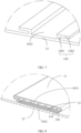
- FIG. 5 is a schematic assembly diagram showing one snap fitting manner between the thermal management component 11 and the protective plate 12 according to this embodiment of this application.
- FIG. 6 is a schematic structural diagram of the thermal management component 11 in FIG. 5 .
- FIG. 7 is a schematic structural diagram of the protective plate 12 in FIG. 5 .
- the first snap-fitting portion 110 is a slot structure.
- the slot structure includes a first slot wall 1101 and a second slot wall 1102 perpendicular to each other, and the first slot wall 1101 is perpendicular to the first surface 1011.
- the second snap-fitting portion 120 is a snap structure.
- the snap structure includes a snap body 1201 and a bent portion 1202 connected to each other, and the snap body 1201 is perpendicular to the second surface 1012.
- the bent portion 1202 abuts against the second slot wall 1102 and is limited between the first slot wall 1101 and the snap body 1201.
- the bent portion 1202 may alternatively be perpendicular to the snap body 1201.
- the first slot wall 1101 and the second slot wall 1102 may form an L shape
- the bent portion 1202 and the snap body 1201 may also form an L shape
- the first snap-fitting portion 110 and the second snap-fitting portion 120 may be reversely snap-fitted.
- first slot wall 1101 may not be perpendicular to the second slot wall 1102, and the bent portion 1202 may not be perpendicular to the snap body 1201 as well, as long as the first snap-fitting portion 110 and the second snap-fitting portion 120 can fit with each other between the thermal management component 11 and the protective plate 12 so as to be snap-fitted.
- the first snap-fitting portion 110 is a slot structure
- the second snap-fitting portion 120 is a snap structure
- the bent portion 1202 of the snap structure abuts against the second slot wall 1102 of the slot structure and is limited between the first slot wall 1101 of the slot structure and the snap body 1201 of the snap structure. Therefore, when the protective plate 12 is the bottom protective plate 16 shown in FIG. 2 , structural stiffness of the box in a height direction can be enhanced, and a spatial size in the height direction is also increased to provide a buffer space, thereby improving a collision prevention effect and also achieving adaptability to various processing implementation manners.
- FIG. 8 is a schematic assembly diagram showing another snap fitting manner between the thermal management component 11 and the protective plate 12 according to this embodiment of this application.
- FIG. 9 is a schematic structural diagram of the thermal management component 11 in FIG. 8 .
- FIG. 10 is a schematic structural diagram of the protective plate 12 in FIG. 8 .
- the first snap-fitting portion 110 is a slot structure
- the second snap-fitting portion 120 is a snap structure.
- An opening of the slot structure faces the second surface 1012, and in a cross section along a first direction, size of the opening of the slot structure is smaller than a maximum size of the slot structure and a maximum size of the snap structure, such that the snap structure is able to be inserted into the slot structure and able to limit movement of the protective plate 12 along a direction perpendicular to the first surface 1011 with respect to the thermal management component 11.
- the first direction is an extension direction of the slot structure.
- the first snap-fitting portion 110 is a slot structure
- the second snap-fitting portion 120 is a snap structure
- the size of the opening of the slot structure is smaller than the maximum size of the slot structure and the maximum size of the snap structure, such that the snap structure is able to be inserted into the slot structure and able to limit movement of the protective plate 12 along a direction perpendicular to the first surface 1011 with respect to the thermal management component 11. Therefore, when the protective plate 12 is the bottom protective plate 16 shown in FIG. 2 , structural stiffness of the box 10 in a height direction can be enhanced, and a spatial size in the height direction is also increased to provide a buffer space, thereby improving the collision prevention effect.
- the cross section of the slot structure along the extension direction of the slot structure is in a first arc shape, and distance between two end points of the first arc shape is less than diameter of the arc shape.
- a cross section of the snap structure along the first direction is in a second arc shape, and diameter of the second arc shape is less than the diameter of the first arc shape and greater than the distance between the two end points of the first arc shape.
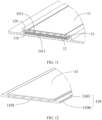
- FIG. 11 is a schematic assembly diagram showing another snap fitting manner between the thermal management component 11 and the protective plate 12 according to this embodiment of this application.
- FIG. 12 is a schematic structural diagram of the thermal management component 11 in FIG. 11 .
- FIG. 13 is a schematic structural diagram of the protective plate 12 in FIG. 11 .
- the first snap-fitting portion 110 is a snap structure
- the second snap-fitting portion 120 is a slot structure.
- the snap structure includes a third surface 1103 and a fourth surface 1104 parallel to each other, where the third surface 1103 is farther away from the second surface 1012 than the fourth surface (1104), and the fourth surface 1104 is an extension surface of the first surface 1011.
- the slot structure includes a third slot wall 1203 and a fourth slot wall 1204 perpendicular to each other, where the third slot wall 1203 is perpendicular to the second surface 1012, and the fourth slot wall 1204 abuts against the third surface 1103 and is limited between the third slot wall 1203 and the side surface of the thermal management component (11).
- the first snap-fitting portion 110 is a snap structure
- the second snap-fitting portion 120 is a slot structure
- the second snap-fitting portion 120 is snap-fitted with the first snap-fitting portion 110 on the side surface of the thermal management component 11. Therefore, when the protective plate 12 is the bottom protective plate 16 shown in FIG. 2 , space of the box in the height direction can be saved, thereby improving space utilization.
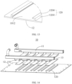
- FIG. 14 is another schematic exploded view of a box 10 according to an embodiment of this application. As shown in FIG. 14 , the box 10 further includes insulating foam 13. The insulating foam 13 is sandwiched between the thermal management component 11 and the protective plate 12.
- the insulating foam 13 can maintain temperature of the thermal management component 11, thereby better improving thermal management performance.
- the insulating foam 13 is disposed between the bent portion 1202 and the first surface 1011 of the thermal management component 11, and the insulating foam 13 may be adhered to the first surface 1011 through a fixing adhesive.
- the insulating foam 13 is fixed between the protective plate 12 and the thermal management component 11 by virtue of a frictional force between the bent portion 1202 and the first surface 1011.
- the insulating foam 13 is disposed between two surfaces, disposed opposite each other, of the thermal management component 11 and the protective plate 12.
- the insulating foam 13 may be adhered to the first surface 1011 of the thermal management component 11 or the second surface 1012 of the protective plate 12 through a fixing adhesive.
- the insulating foam 13 is fixed between the thermal management component 11 and the protective plate 12 by virtue of a frictional force between the first surface 1011 of the thermal management component 11 and the second surface 1012 of the protective plate 12.
- the insulating foam 13 is disposed between two surfaces, disposed opposite each other, of the thermal management component 11 and the protective plate 12.
- the insulating foam 13 may be adhered to the first surface 1011 of the thermal management component 11 or the second surface 1012 of the protective plate 12 through a fixing adhesive.
- the insulating foam 13 is fixed between the thermal management component 11 and the protective plate 12 by virtue of a frictional force between the first surface 1011 of the thermal management component 11 and the second surface 1012 of the protective plate 12.
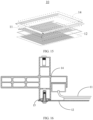
- the box 10 may further include a frame 14 perpendicular to the protective plate 12 and disposed around the battery cell 20, where the frame 14 is fixedly connected to the protective plate 12.
- the thermal management component 11 and the protective plate 12 are snap-fitted, and the protective plate 12 and the frame 14 are fixedly connected, such that the thermal management component 11 can be limited in all directions, thereby improving the overall mechanical structural performance of the box 10.
- FIG. 16 is a schematic enlarged view of a joint between the frame 14 and the protective plate 12.
- the box 10 further includes a sealing structure 15, where the sealing structure 15 is disposed between the frame 14 and the protective plate 12.
- the sealing structure 15 is disposed between the frame 14 and the protective plate 12 and at the joint between the frame 14 and the protective plate 12.
- the sealing structure 15 disposed between the protective plate 12 and the frame 14 can improve airtightness of the box 10, thereby improving the safety of the battery.
- the sealing structure 15 includes a sealing adhesive and/or a sealing gasket.
- the frame 14 and the protective plate 12 are fixedly connected through riveting of a flow drill screw (flow drill screw, FDS), friction stir welding (friction stir welding, FSW), or a bolt.
- FDS flow drill screw
- FSW friction stir welding
- bolt a bolt
- an embodiment of this application further provides a battery 100.
- the battery 100 includes a battery cell 20 and a box 10, where the box 10 is configured to accommodate the battery cell 20.
- the box 10 may be the box 10 according to any one of the embodiments described above.
- the structure of the battery cell 20 reference may be made to the structure of the battery cell 20 shown in FIG. 3 .
- details are not described herein again.
- An embodiment of this application further provides an electric apparatus, where the electric apparatus may include the battery 100 in the foregoing embodiments, and the battery 100 is configured to provide electrical energy for the electric apparatus.
- the electric apparatus may be a vehicle 1, a ship, or a spacecraft.
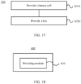
- FIG. 17 is a schematic flowchart of a method 300 for manufacturing battery according to an embodiment of this application.
- the battery may be the battery 100 provided in the foregoing embodiments.
- the method 300 may include the following steps.
- S320 Provide a box 10 for accommodating the battery cell 20.
- the box 10 includes: a thermal management component 11, where the thermal management component 11 is configured to regulate temperature of the battery cell 20; and a protective plate 12, disposed at a side of the thermal management component 11 away from the battery cell 20 and configured to protect the thermal management component 11.
- the thermal management component 11 is provided with a first snap-fitting portion 110
- the protective plate 12 is provided with a second snap-fitting portion 120.
- the first snap-fitting portion 110 and the second snap-fitting portion 120 are snap-fitted to connect the thermal management component 11 and the protective plate 12.
- FIG. 18 is a schematic block diagram of an apparatus 400 for manufacturing battery according to an embodiment of this application.
- the battery may be the battery 100 provided in the foregoing embodiments.
- the apparatus 400 for manufacturing battery may include a providing module 410.
- the providing module 410 is configured to provide a battery cell 20 and provide a box 10 for accommodating the battery cell 20.
- the box 10 includes: a thermal management component 11, where the thermal management component 11 is configured to regulate temperature of the battery cell 20; and a protective plate 12, disposed at a side of the thermal management component 11 away from the battery cell 20 and configured to protect the thermal management component 11.
- the thermal management component 11 is provided with a first snap-fitting portion 110
- the protective plate 12 is provided with a second snap-fitting portion 120.
- the first snap-fitting portion 110 and the second snap-fitting portion 120 are snap-fitted to connect the thermal management component 11 and the protective plate 12.
Landscapes
- Engineering & Computer Science (AREA)
- Chemical & Material Sciences (AREA)
- Chemical Kinetics & Catalysis (AREA)
- Electrochemistry (AREA)
- General Chemical & Material Sciences (AREA)
- Manufacturing & Machinery (AREA)
- Aviation & Aerospace Engineering (AREA)
- Physics & Mathematics (AREA)
- Thermal Sciences (AREA)
- Mechanical Engineering (AREA)
- General Engineering & Computer Science (AREA)
- Battery Mounting, Suspending (AREA)
Abstract
Description
- This application claims priority to Utility Model Application No.
202220427432.0, filed on February 28, 2022 - This application relates to the field of battery technologies, and more specifically, to a box, a battery, an electric apparatus, and an apparatus for manufacturing battery.
- Energy conservation and emission reduction are crucial to sustainable development of the automobile industry. In this context, electric vehicles, with their advantages in energy conservation and environmental protection, have become an important part of sustainable development of the automobile industry. For electric vehicles, battery technology is an important factor in connection with their development.
- In the development of battery technology, in addition to battery performance improvement, safety is another non-negligible issue. If the safety of a battery cannot be guaranteed, the battery cannot be used. Therefore, how safety performance of batteries is enhanced is an urgent technical problem that needs to be solved in battery technology.
- In view of this, this application provides a box, a battery, an electric apparatus, and an apparatus for manufacturing battery, aiming to improve safety performance of batteries.
- According to a first aspect, a box is provided for accommodating a battery cell, characterized by including: a thermal management component, where the thermal management component is configured to regulate temperature of the battery cell; and a protective plate, disposed at a side of the thermal management component away from the battery cell and configured to protect the thermal management component. The thermal management component is provided with a first snap-fitting portion, and the protective plate is provided with a second snap-fitting portion. The first snap-fitting portion and the second snap-fitting portion are snap-fitted to connect the thermal management component and the protective plate.
- In this embodiment, the thermal management component is provided with the first snap-fitting portion, the protective plate is provided with the second snap-fitting portion, and the first snap-fitting portion and the second snap-fitting portion are snap-fitted, so that the thermal management component and the protective plate can be quickly fitted together, achieving stability and reliability, thereby improving overall mechanical structural performance of the box. Moreover, since the thermal management component and the protective plate can be fitted together, the assembly efficiency of the box can be improved. In addition, the snap fitting between the thermal management component and the protective plate can also prevent collision, thereby improving the safety performance of a battery.
- In a possible embodiment, the thermal management component includes multiple groups of fluid pipelines, where each of the multiple groups of fluid pipelines is provided with a first snap-fitting portion; the protective plate is provided with a second snap-fitting portion corresponding to each group of fluid pipelines; and each group of fluid pipelines and the protective plate are snap-fitted via the first snap-fitting portion and the second snap-fitting portion.
- In this embodiment, the thermal management component includes multiple groups of fluid pipelines, and each group of fluid pipelines and the protective plate can be snap-fitted via the first snap-fitting portion and the second snap-fitting portion, thereby further improving the overall mechanical structural performance of the box.
- In a possible embodiment, the first snap-fitting portion and the second snap-fitting portion extend along the same direction as the fluid pipelines extend.
- In a possible implementation, each group of fluid pipelines is provided with one pair of first snap-fitting portions respectively located at two sides of a corresponding group of fluid pipelines.
- In this embodiment, with one pair of first snap-fitting portions disposed at two sides of each group of fluid pipelines, structural stability between each group of fluid pipelines and the protective plate can be improved.
- In a possible embodiment, the thermal management component further includes two flow gathering pipes, where two ends of each group of fluid pipelines are respectively connected to the two flow gathering pipes, and the multiple groups of fluid pipelines are spaced apart along an extension direction of the flow gathering pipes.
- In this embodiment, the flow gathering pipes can not only connect the multiple groups of fluid pipelines, but also allow for convenient management for a fluid flowing into or out of the fluid pipelines.
- In a possible embodiment, one of the first snap-fitting portion and the second snap-fitting portion is a slot structure, and the other one of the first snap-fitting portion and the second snap-fitting portion is a snap structure, where the snap structure is inserted into the slot structure to implement snap fitting between the first snap-fitting portion and the second snap-fitting portion.
- In this embodiment, the first snap-fitting portion and the second snap-fitting portion are snap-fitted via the snap structure and the slot structure, improving the reliability of the connection between the thermal management component and the protective plate.
- In a possible embodiment, the first snap-fitting portion extends toward the protective plate from a first surface of the thermal management component, and the second snap-fitting portion extends toward the thermal management component from a second surface of the protective plate. The first surface and the second surface are opposite each other. The first snap-fitting portion and the second snap-fitting portion are snap-fitted between the first surface and the second surface to connect the thermal management component and the protective plate.
- In a possible embodiment, the first snap-fitting portion is a slot structure. The slot structure includes a first slot wall and a second slot wall perpendicular to each other, and the first slot wall is perpendicular to the first surface. The second snap-fitting portion is a snap structure. The snap structure includes a snap body and a bent portion connected to each other, and the snap body is perpendicular to the second surface. The bent portion abuts against the second slot wall and is limited between the first slot wall and the snap body.
- In this embodiment, the first snap-fitting portion is a slot structure, the second snap-fitting portion is a snap structure, and the bent portion of the snap structure abuts against the second slot wall of the slot structure and is limited between the first slot wall of the slot structure and the snap body of the snap structure. Therefore, when the protective plate is a bottom protective plate, structural stiffness of the box in a height direction can be enhanced, and a spatial size in the height direction is also increased to provide a buffer space, thereby improving a collision prevention effect, and also achieving adaptability to various processing implementation manners.
- In a possible embodiment, the first snap-fitting portion is a slot structure, and the second snap-fitting portion is a snap structure, where an opening of the slot structure faces the second surface, and in a cross section along an extension direction of the slot structure, size of the opening of the slot structure is smaller than a maximum size of the slot structure and a maximum size of the snap structure, such that the snap structure is able to be inserted into the slot structure and able to limit movement of the protective plate along a direction perpendicular to the first surface with respect to the thermal management component.
- In this embodiment, the first snap-fitting portion is a slot structure, the second snap-fitting portion is a snap structure, and in the cross section along the extension direction of the slot structure, the size of the opening of the slot structure is smaller than the maximum size of the slot structure and the maximum size of the snap structure, such that the snap structure is able to be inserted into the slot structure and able to limit movement of the protective plate along a direction perpendicular to the first surface with respect to the thermal management component. Therefore, when the protective plate is a bottom protective plate, structural stiffness of the box in a height direction can be enhanced, and a spatial size in the height direction is also increased to provide a buffer space, thereby improving a collision prevention effect.
- In a possible embodiment, the cross section of the slot structure along the extension direction of the slot structure is in a first arc shape, and distance between two end points of the first arc shape is less than diameter of the arc shape. A cross section of the snap structure along the first direction is in a second arc shape, and diameter of the second arc shape is less than the diameter of the first arc shape and greater than the distance between the two end points of the first arc shape.
- In a possible embodiment, the first snap-fitting portion extends along a direction parallel to the first surface of the thermal management component from a side surface of the thermal management component, and the second snap-fitting portion extends from the second surface of the protective plate along a direction leaving the second surface and is snap-fitted with the first snap-fitting portion on the side surface of the thermal management component, so as to connect the thermal management component and the protective plate, where the first surface and the second surface are opposite each other.
- In this embodiment, the first snap-fitting portion is a snap structure, the second snap-fitting portion is a slot structure, and the second snap-fitting portion is snap-fitted with the first snap-fitting portion on the side surface of the thermal management component. Therefore, when the protective plate is a bottom protective plate, space of the box in a height direction can be saved, thereby improving space utilization.
- In a possible embodiment, the first snap-fitting portion is a snap structure, and the second snap-fitting portion is a slot structure. The snap structure includes a third surface and a fourth surface parallel to each other. The third surface is farther away from the second surface than the fourth surface, the fourth surface is an extension surface of the first surface, and in a direction perpendicular to the first surface, size of the snap structure is smaller than size of the thermal management component. The slot structure includes a third slot wall and a fourth slot wall perpendicular to each other, the third slot wall is perpendicular to the second surface, and the fourth slot wall abuts against the third surface and is limited between the third slot wall and the side surface of the thermal management component.
- In a possible embodiment, the box further includes insulating foam sandwiched between the protective plate and the thermal management component.
- In this embodiment, the insulating foam can maintain temperature of the thermal management component, thereby better improving thermal management performance.
- In a possible embodiment, the box further includes a frame perpendicular to the protective plate and disposed around the battery cell, where the frame is fixedly connected to the protective plate.
- In this embodiment, the thermal management component and the protective plate are snap-fitted, and the protective plate and the frame are fixedly connected, so that the thermal management component can be limited in all directions, thereby improving the overall mechanical structural performance of the box.
- In a possible embodiment, the box further includes a sealing structure disposed between the frame and the protective plate.
- In this embodiment, the sealing structure disposed between the protective plate and the frame can improve airtightness of the box, thereby improving the safety of the battery.
- In a possible embodiment, the sealing structure includes a sealing gasket and/or a sealing adhesive.
- In a possible embodiment, the frame is fixedly connected to the protective plate through riveting of a flow drill screw, friction stir welding, or a bolt.
- According to a second aspect, a battery is provided, including multiple battery cells and the box according to the first aspect or any one of the possible embodiments, where the multiple battery cells are accommodated in the box.
- According to a third aspect, an electric apparatus is provided, including the battery according to the second aspect, where the battery is configured to provide electrical energy for the electric apparatus.
- According to a fourth aspect, an apparatus for manufacturing battery is provided, including: a providing module, configured to provide a battery cell and provide a box for accommodating the battery cell. The box includes: a thermal management component, where the thermal management component is configured to regulate temperature of the battery cell; and a protective plate, disposed at a side of the thermal management component away from the battery cell and configured to protect the thermal management component. The thermal management component is provided with a first snap-fitting portion, and the protective plate is provided with a second snap-fitting portion. The first snap-fitting portion and the second snap-fitting portion are snap-fitted to connect the thermal management component and the protective plate.
-
-
FIG. 1 is a schematic structural diagram of a vehicle according to an embodiment of this application. -
FIG. 2 is a schematic structural diagram of a battery according to an embodiment of this application. -
FIG. 3 is a schematic exploded view of a box according to an embodiment of this application. -
FIG. 4 is a schematic structural diagram of a thermal management component according to an embodiment of this application. -
FIG. 5 is a schematic assembly diagram showing one snap fitting manner between a thermal management component and a protective plate according to an embodiment of this application. -
FIG. 6 is a schematic structural diagram of the thermal management component inFIG. 5 . -
FIG. 7 is a schematic structural diagram of the protective plate inFIG. 5 . -
FIG. 8 is a schematic assembly diagram showing one snap fitting manner between a thermal management component and a protective plate according to an embodiment of this application. -
FIG. 9 is a schematic structural diagram of the thermal management component inFIG. 8 . -
FIG. 10 is a schematic structural diagram of the protective plate inFIG. 8 . -
FIG. 11 is a schematic assembly diagram showing one snap fitting manner between a thermal management component and a protective plate according to an embodiment of this application. -
FIG. 12 is a schematic structural diagram of the thermal management component inFIG. 11 . -
FIG. 13 is a schematic structural diagram of the protective plate inFIG. 11 . -
FIG. 14 is a schematic exploded view of a box according to an embodiment of this application. -
FIG. 15 is a schematic exploded view of a box according to an embodiment of this application. -
FIG. 16 is a schematic diagram of a connection between a frame and a protective plate inFIG. 15 . -
FIG. 17 is a schematic block diagram of a method for manufacturing battery according to an embodiment of this application. -
FIG. 18 is a schematic block diagram of an apparatus for manufacturing battery according to an embodiment of this application. - To make the objectives, technical solutions, and advantages of the embodiments of this application clearer, the following clearly describes the technical solutions in the embodiments of this application with reference to the accompanying drawings in the embodiments of this application. It will be apparent that the embodiments described are some rather than all embodiments of this application. All other embodiments obtained by persons of ordinary skill in the art based on the embodiments of this application without creative efforts shall fall within the protection scope of this application.
- Unless otherwise defined, all technical and scientific terms used in this application shall have the same meanings as commonly understood by those skilled in the art to which this application relates. The terms used in the specification of this application are intended to merely describe the specific embodiments rather than to limit this application. The terms "include", "comprise", and any variations thereof in the specification and claims of this application as well as the foregoing description of drawings are intended to cover non-exclusive inclusions. In the specification, claims, or accompanying drawings of this application, the terms "first", "second", and the like are intended to distinguish between different objects rather than to indicate a particular sequence or relative importance.
- The orientation terms appearing in the following description all refer to directions shown in the figures, and do not limit the specific structure of this application. In the description of this application, it should also be noted that unless otherwise specified and defined explicitly, the terms "mounting", "connection", and "join" should be understood in their general senses. For example, they may refer to a fixed connection, a detachable connection, or an integral connection, and may refer to a direct connection or an indirect connection via an intermediate medium. Persons of ordinary skill in the art can understand specific meanings of these terms in this application as appropriate to specific situations.
- Reference to "embodiment" in this application means that specific features, structures, or characteristics described with reference to the embodiment may be included in at least one embodiment of this application. The word "embodiment" appearing in various places in the specification does not necessarily refer to the same embodiment or an independent or alternative embodiment that is exclusive of other embodiments. It is explicitly or implicitly understood by persons skilled in the art that the embodiments described herein may be combined with other embodiments.
- In the description of this application, it should be noted that unless otherwise specified and defined explicitly, the terms "mounting", "connection", "join", and "attachment" should be understood in their general senses. For example, they may refer to a fixed connection, a detachable connection, or an integral connection, and may refer to a direct connection, an indirect connection via an intermediate medium, or an internal communication between two elements. Persons of ordinary skill in the art can understand specific meanings of these terms in this application as appropriate to specific situations.
- The term "and/or" in this application is only an associative relationship for describing associated objects, indicating that three relationships may be present. For example, A and/or B may indicate three cases: presence of only A; presence of both A and B; and presence of only B. In addition, the character "/" in this application generally indicates an "or" relationship between contextually associated objects.
- In this application, "multiple" means more than two (inclusive). Similarly, "multiple groups" means more than two (inclusive) groups, and "multiple pieces" means more than two (inclusive) pieces.
- In this application, the battery cell may be a lithium-ion secondary battery, a lithium-ion primary battery, a lithium-sulfur battery, a sodium-lithium-ion battery, a sodium-ion battery, a magnesium-ion battery, or the like. This is not limited in the embodiments of this application. The battery cell may be cylindrical, flat, cuboid, or of other shapes. This is not limited in the embodiments of this application either. Battery cells are typically divided into three types by packaging method: cylindrical cell, prismatic cell, and pouch cell. This is not limited in the embodiments of this application either.
- The battery mentioned in the embodiments of this application is a single physical module that includes one or more battery cells for providing a higher voltage and capacity. For example, the battery mentioned in this application may include a battery module, a battery pack, or the like. A battery typically includes a box configured to enclose one or more battery cells. The box can prevent liquids or other foreign matter from affecting charging or discharging of the battery cell.
- At present, in a box of a battery integrated with a thermal management component, the thermal management component and a bottom protective plate are separately assembled, to be specific, the bottom protective plate is firstly assembled onto a frame of the box, then the thermal management component is placed on the bottom protective plate, and the thermal management component and the bottom protective plate are not fixed or fixed through adhesion, resulting in insufficient overall stiffness between the thermal management component and the bottom protective plate. As a result, when the bottom of an electric apparatus such as a vehicle is impacted, the insufficient stiffness between the thermal management component and the bottom protective plate may cause damage to the battery, thus affecting the safety of the battery.
- In view of this, the embodiments of this application provide a technical solution, in which the thermal management component and the protective plate are fixed through snap fitting, improving the overall mechanical structural performance of the box. In addition, the snap fitting between the thermal management component and the protective plate can also prevent collision, thereby improving the safety performance of a battery.
- The technical solutions described in the embodiments of this application are all applicable to various apparatuses that use batteries, for example, mobile phones, portable devices, notebook computers, electric bicycles, electric toys, electric tools, electric vehicles, ships, and spacecrafts. For example, spacecrafts include airplanes, rockets, space shuttles, and spaceships.
- It should be understood that the technical solutions described in the embodiments of this application are not only applicable to the devices described above, but also applicable to all devices using batteries. However, for brevity of description, electric vehicles are used as an example for description in the following embodiments.
- For example,
FIG. 1 is a schematic structural diagram of avehicle 1 according to an embodiment of this application. Thevehicle 1 may be a fossil fuel vehicle, a natural-gas vehicle, or a new energy vehicle, where the new energy vehicle may be a battery electric vehicle, a hybrid electric vehicle, a range-extended vehicle, or the like. Thevehicle 1 may be provided with amotor 80, acontroller 60, and abattery 100 inside, where thecontroller 60 is configured to control thebattery 100 to supply power to themotor 80. For example, thebattery 100 may be disposed at the bottom, front, or rear of thevehicle 1. Thebattery 100 may be configured to supply power to thevehicle 1. For example, thebattery 100 may be used as an operational power source for thevehicle 1 for use in a circuit system of thevehicle 1, for example, to satisfy power needs of start, navigation, and running of thevehicle 1. In another embodiment of this application, thebattery 100 may be used not only as the operational power source for thevehicle 1, but also as a driving power source for thevehicle 1, replacing or partially replacing fossil fuel or natural gas to provide driving traction for thevehicle 1. - To meet different power usage requirements, the battery may include multiple battery cells, and the multiple battery cells may be connected in series, parallel, or series-parallel, where being connected in series-parallel means a combination of series and parallel connections. The battery may also be referred to as a battery pack. Optionally, multiple battery cells may be connected in series, parallel, or series-parallel to form a battery module first, and then multiple battery modules are connected in series, parallel, or series-parallel to form a battery. In other words, the multiple battery cells may be directly combined into a battery, or may first be combined into battery modules that are then combined into a battery.
- For example,
FIG. 2 is a schematic structural diagram of abattery 100 according to an embodiment of this application. Thebattery 100 may includemultiple battery cells 20. Thebattery 100 may further include a box (or a cover body) that has a hollow structure inside, and themultiple battery cells 20 are accommodated in the box. As shown inFIG. 2 , the box may include two portions that are referred to herein as afirst portion 101 and asecond portion 102 respectively. Thefirst portion 101 and thesecond portion 102 are snap-fitted together. Shapes of thefirst portion 101 and thesecond portion 102 may be determined based on a shape of themultiple battery cells 20 that are combined, and thefirst portion 101 and thesecond portion 102 each may have an opening. For example, thefirst portion 101 and thesecond portion 102 may each be a hollow cuboid and each have only one open surface. The opening of thefirst portion 101 and the opening of thesecond portion 102 are disposed opposite each other, and thefirst portion 101 and thesecond portion 102 are snap-fitted to form the box with a closed cavity. Themultiple battery cells 20 are connected in parallel, series, or series-parallel, and then placed into the box formed by thefirst portion 101 and thesecond portion 102 that are snap-fitted. - Optionally, the
first portion 101 and thesecond portion 102 may include two portions. For example, thesecond portion 102 is formed by a bottomprotective plate 16 and asecond sub-frame 142, while thefirst portion 101 is formed by a top cover plate (not shown in the figure) and afirst sub-frame 141, where thefirst sub-frame 141 and thesecond sub-frame 142 jointly form aframe 14, that is, thefirst sub-frame 141 and thesecond sub-frame 142 may be integrally formed. In other words, the box of thebattery 100 may alternatively be formed by the top cover plate (not shown in the figure), theframe 14, and the bottomprotective plate 16 together. A specific constitution manner of the box is not limited in this embodiment of this application. - Optionally, the
battery 100 may further include other structures. Details are not described herein. -
FIG. 3 is a schematic exploded view of abox 10 according to an embodiment of this application. Thebox 10 is configured to accommodate thebattery cell 20. As shown inFIG. 3 , thebox 10 includes athermal management component 11 and aprotective plate 12. Thethermal management component 11 is configured to regulate temperature of thebattery cell 20. Theprotective plate 12 is disposed at a side of thethermal management component 11 away from thebattery cell 20 and is configured to protect thethermal management component 11. Thethermal management component 11 is provided with a first snap-fitting portion 110, and theprotective plate 12 is provided with a second snap-fitting portion 120. The first snap-fitting portion 110 and the second snap-fitting portion 120 are snap-fitted to connect thethermal management component 11 and theprotective plate 12. - It should be understood that the
protective plate 12 shown inFIG. 3 may be the bottomprotective plate 16 inFIG. 2 , in other words, theprotective plate 12 may be disposed below thebattery cell 20. Optionally, theprotective plate 12 may alternatively be disposed at either side of thebattery cell 20. Thethermal management component 11 is parallel to theprotective plate 12 and is disposed between theprotective plate 12 and thebattery cell 20. In other words, thethermal management component 11 and theprotective plate 12 are fixedly connected through snap fitting to jointly form any wall of thebox 10. - Typically, the
thermal management component 11 is configured to accommodate a fluid to regulate temperature of thebattery cell 20. The fluid herein may be liquid or gas. Regulating temperature means heating or cooling thebattery cell 20. In a case of cooling or lowering the temperature of thebattery cell 20, thethermal management component 11 is configured to accommodate a cooling fluid to lower the temperature of thebattery cell 20. In this case, thethermal management component 11 may also be referred to as a cooling component, a cooling system, a cooling plate, or the like. The fluid accommodated therein may also be referred to as a cooling medium or cooling fluid, and more specifically, a cooling liquid or cooling gas. In addition, thethermal management component 11 may alternatively be configured to heat and raise the temperature of thebattery cell 20. This is not limited in this embodiment of this application. Optionally, the fluid may flow circularly to achieve a better temperature regulation effect. Optionally, the fluid may be water, a solution mixture of water and ethylene glycol, air, or the like. - Therefore, in the
box 10 provided in this embodiment of this application, thethermal management component 11 is provided with the first snap-fitting portion 110, theprotective plate 12 is provided with the second snap-fitting portion 120, and the first snap-fitting portion 110 and the second snap-fitting portion 120 are snap-fitted, so that thethermal management component 11 and theprotective plate 12 can be quickly fitted together, achieving stability and reliability, thereby improving the overall mechanical structural performance of thebox 10. Moreover, since thethermal management component 11 and theprotective plate 12 can be fitted together, the assembly efficiency of thebox 10 can be improved. In addition, the snap fitting between thethermal management component 11 and theprotective plate 12 can also prevent collision, thereby improving the safety performance of the battery. - Optionally, the
thermal management component 11 may be provided with a fluid pipeline for accommodating a fluid. For example, thethermal management component 11 is formed by multiple first metal plates provided with grooves and a flat second metal plate, where the second metal plate covers multiple grooves on the first metal plates to form the fluid pipeline with multiple cavities. - Optionally, as shown in
FIG. 4 , thethermal management component 11 includes multiple groups offluid pipelines 111, where each of the multiple groups offluid pipelines 111 is provided with a first snap-fitting portion 110; theprotective plate 12 is provided with a second snap-fitting portion 120 corresponding to each group offluid pipelines 111; and each group offluid pipelines 111 and theprotective plate 12 are snap-fitted via the first snap-fitting portion 110 and the second snap-fitting portion 120. - In this embodiment, the
thermal management component 11 includes multiple groups offluid pipelines 111, and each group offluid pipelines 111 and theprotective plate 12 can be snap-fitted via the first snap-fitting portion 110 and the second snap-fitting portion 120, thereby further improving the overall mechanical structural performance of thebox 10. - Optionally, as shown in
FIG. 4 , thethermal management component 11 further includes twoflow gathering pipes 112, where two ends of each group offluid pipelines 111 are respectively connected to the twoflow gathering pipes 112, and the multiple groups offluid pipelines 111 are spaced apart along an extension direction of theflow gathering pipes 112. - In this embodiment, the
flow gathering pipes 112 can not only connect the multiple groups offluid pipelines 111, but also allow for convenient management for a fluid flowing into or out of thefluid pipelines 111. - Optionally, as shown in
FIG. 4 , the first snap-fitting portion 110 and the second snap-fitting portion 120 extend along the same direction as thefluid pipelines 111 extend. - Optionally, as shown in
FIG. 4 , each group offluid pipelines 111 is provided with one pair of first snap-fittingportions 110 respectively located at two sides of a corresponding group offluid pipelines 111. - In this embodiment, with one pair of first snap-fitting
portions 110 disposed at two sides of each group offluid pipelines 111, structural stability between each group offluid pipelines 111 and theprotective plate 12 can be improved. - Optionally, in this embodiment of this application, one of the first snap-
fitting portion 110 and the second snap-fitting portion 120 is a slot structure, and the other one of the first snap-fitting portion 110 and the second snap-fitting portion 120 is a snap structure, where the snap structure is inserted into the slot structure to implement snap fitting between the first snap-fitting portion 110 and the second snap-fitting portion 120. - In this embodiment, the first snap-
fitting portion 110 and the second snap-fitting portion 120 are snap-fitted via the snap structure and the slot structure, improving the reliability of the connection between thethermal management component 11 and theprotective plate 12. - In an embodiment, the first snap-
fitting portion 110 and the second snap-fitting portion 120 may be snap-fitted between thethermal management component 11 and theprotective plate 12, so as to connect thethermal management component 11 and theprotective plate 12. Optionally, as shown inFIG. 5 to FIG. 10 , the first snap-fitting portion 110 extends toward theprotective plate 12 from afirst surface 1011 of thethermal management component 11, and the second snap-fitting portion 120 extends toward thethermal management component 11 from asecond surface 1012 of theprotective plate 12, where thefirst surface 1011 and thesecond surface 1012 are opposite each other, and the first snap-fitting portion 110 and the second snap-fitting portion 120 are snap-fitted between thefirst surface 1011 and thesecond surface 1012 to connect thethermal management component 11 and theprotective plate 12. - In another embodiment, the first snap-
fitting portion 110 and the second snap-fitting portion 120 may alternatively be snap-fitted on a side surface of thethermal management component 11, so as to connect thethermal management component 11 and theprotective plate 12. Optionally, as shown inFIG. 11 to FIG. 13 , the first snap-fitting portion 110 extends along a direction parallel to thefirst surface 1011 of thethermal management component 11 from a side surface of thethermal management component 11, and the second snap-fitting portion 120 extends from thesecond surface 1012 of theprotective plate 12 along a direction leaving thesecond surface 1012 and is snap-fitted with the first snap-fitting portion 110 on the side surface of thethermal management component 11, so as to connect thethermal management component 11 and theprotective plate 12, where thefirst surface 1011 and thesecond surface 1012 are opposite each other. - An example in which one of the first snap-
fitting portion 110 and the second snap-fitting portion 120 is a slot structure and the other one is a snap structure is used below for describing various snap fitting manners between thethermal management component 11 and theprotective plate 12 in this embodiment of this application with reference toFIG. 5 to FIG. 13 . -
FIG. 5 is a schematic assembly diagram showing one snap fitting manner between thethermal management component 11 and theprotective plate 12 according to this embodiment of this application.FIG. 6 is a schematic structural diagram of thethermal management component 11 inFIG. 5 .FIG. 7 is a schematic structural diagram of theprotective plate 12 inFIG. 5 . As shown inFIG. 5 to FIG. 7 , the first snap-fitting portion 110 is a slot structure. The slot structure includes afirst slot wall 1101 and asecond slot wall 1102 perpendicular to each other, and thefirst slot wall 1101 is perpendicular to thefirst surface 1011. The second snap-fitting portion 120 is a snap structure. The snap structure includes asnap body 1201 and abent portion 1202 connected to each other, and thesnap body 1201 is perpendicular to thesecond surface 1012. Thebent portion 1202 abuts against thesecond slot wall 1102 and is limited between thefirst slot wall 1101 and thesnap body 1201. - Optionally, in this embodiment of this application, the
bent portion 1202 may alternatively be perpendicular to thesnap body 1201. Specifically, thefirst slot wall 1101 and thesecond slot wall 1102 may form an L shape, thebent portion 1202 and thesnap body 1201 may also form an L shape, and the first snap-fitting portion 110 and the second snap-fitting portion 120 may be reversely snap-fitted. - In other embodiments of this application, the
first slot wall 1101 may not be perpendicular to thesecond slot wall 1102, and thebent portion 1202 may not be perpendicular to thesnap body 1201 as well, as long as the first snap-fitting portion 110 and the second snap-fitting portion 120 can fit with each other between thethermal management component 11 and theprotective plate 12 so as to be snap-fitted. - In this embodiment, the first snap-
fitting portion 110 is a slot structure, the second snap-fitting portion 120 is a snap structure, and thebent portion 1202 of the snap structure abuts against thesecond slot wall 1102 of the slot structure and is limited between thefirst slot wall 1101 of the slot structure and thesnap body 1201 of the snap structure. Therefore, when theprotective plate 12 is the bottomprotective plate 16 shown inFIG. 2 , structural stiffness of the box in a height direction can be enhanced, and a spatial size in the height direction is also increased to provide a buffer space, thereby improving a collision prevention effect and also achieving adaptability to various processing implementation manners. -
FIG. 8 is a schematic assembly diagram showing another snap fitting manner between thethermal management component 11 and theprotective plate 12 according to this embodiment of this application.FIG. 9 is a schematic structural diagram of thethermal management component 11 inFIG. 8 .FIG. 10 is a schematic structural diagram of theprotective plate 12 inFIG. 8 . As shown inFIG. 8 to FIG. 10 , the first snap-fitting portion 110 is a slot structure, and the second snap-fitting portion 120 is a snap structure. An opening of the slot structure faces thesecond surface 1012, and in a cross section along a first direction, size of the opening of the slot structure is smaller than a maximum size of the slot structure and a maximum size of the snap structure, such that the snap structure is able to be inserted into the slot structure and able to limit movement of theprotective plate 12 along a direction perpendicular to thefirst surface 1011 with respect to thethermal management component 11. The first direction is an extension direction of the slot structure. - In this embodiment, the first snap-
fitting portion 110 is a slot structure, the second snap-fitting portion 120 is a snap structure, and in the cross section along the extension direction of the slot structure, the size of the opening of the slot structure is smaller than the maximum size of the slot structure and the maximum size of the snap structure, such that the snap structure is able to be inserted into the slot structure and able to limit movement of theprotective plate 12 along a direction perpendicular to thefirst surface 1011 with respect to thethermal management component 11. Therefore, when theprotective plate 12 is the bottomprotective plate 16 shown inFIG. 2 , structural stiffness of thebox 10 in a height direction can be enhanced, and a spatial size in the height direction is also increased to provide a buffer space, thereby improving the collision prevention effect. - Optionally, in this embodiment of this application, the cross section of the slot structure along the extension direction of the slot structure is in a first arc shape, and distance between two end points of the first arc shape is less than diameter of the arc shape. A cross section of the snap structure along the first direction is in a second arc shape, and diameter of the second arc shape is less than the diameter of the first arc shape and greater than the distance between the two end points of the first arc shape.
-
FIG. 11 is a schematic assembly diagram showing another snap fitting manner between thethermal management component 11 and theprotective plate 12 according to this embodiment of this application.FIG. 12 is a schematic structural diagram of thethermal management component 11 inFIG. 11 .FIG. 13 is a schematic structural diagram of theprotective plate 12 inFIG. 11 . As shown inFIG. 11 to FIG. 13 , the first snap-fitting portion 110 is a snap structure, and the second snap-fitting portion 120 is a slot structure. The snap structure includes athird surface 1103 and afourth surface 1104 parallel to each other, where thethird surface 1103 is farther away from thesecond surface 1012 than the fourth surface (1104), and thefourth surface 1104 is an extension surface of thefirst surface 1011. In a direction perpendicular to thefirst surface 1011, size of the snap structure is smaller than size of thethermal management component 11. The slot structure includes athird slot wall 1203 and afourth slot wall 1204 perpendicular to each other, where thethird slot wall 1203 is perpendicular to thesecond surface 1012, and thefourth slot wall 1204 abuts against thethird surface 1103 and is limited between thethird slot wall 1203 and the side surface of the thermal management component (11). - In this embodiment, the first snap-
fitting portion 110 is a snap structure, the second snap-fitting portion 120 is a slot structure, and the second snap-fitting portion 120 is snap-fitted with the first snap-fitting portion 110 on the side surface of thethermal management component 11. Therefore, when theprotective plate 12 is the bottomprotective plate 16 shown inFIG. 2 , space of the box in the height direction can be saved, thereby improving space utilization. - It should be noted that although the foregoing three snap fitting manners are shown in this embodiment of this application, persons skilled in the art understand that this embodiment of this application is not limited to the three snap fitting manners. All manners fall within the protection scope of this application, as long as the
thermal management component 11 and theprotective plate 12 are snap-fitted. - In addition, the foregoing three snap fitting manners may be used alone or used together. This is not limited in this embodiment of this application.
-
FIG. 14 is another schematic exploded view of abox 10 according to an embodiment of this application. As shown inFIG. 14 , thebox 10 further includes insulatingfoam 13. The insulatingfoam 13 is sandwiched between thethermal management component 11 and theprotective plate 12. - In this embodiment, the insulating
foam 13 can maintain temperature of thethermal management component 11, thereby better improving thermal management performance. - Optionally, in a snap fitting manner shown in
FIG. 5 , the insulatingfoam 13 is disposed between thebent portion 1202 and thefirst surface 1011 of thethermal management component 11, and the insulatingfoam 13 may be adhered to thefirst surface 1011 through a fixing adhesive. Alternatively, the insulatingfoam 13 is fixed between theprotective plate 12 and thethermal management component 11 by virtue of a frictional force between thebent portion 1202 and thefirst surface 1011. - Optionally, in a snap fitting manner shown in
FIG. 8 , the insulatingfoam 13 is disposed between two surfaces, disposed opposite each other, of thethermal management component 11 and theprotective plate 12. The insulatingfoam 13 may be adhered to thefirst surface 1011 of thethermal management component 11 or thesecond surface 1012 of theprotective plate 12 through a fixing adhesive. Alternatively, the insulatingfoam 13 is fixed between thethermal management component 11 and theprotective plate 12 by virtue of a frictional force between thefirst surface 1011 of thethermal management component 11 and thesecond surface 1012 of theprotective plate 12. - Optionally, in a snap fitting manner shown in
FIG. 11 , the insulatingfoam 13 is disposed between two surfaces, disposed opposite each other, of thethermal management component 11 and theprotective plate 12. The insulatingfoam 13 may be adhered to thefirst surface 1011 of thethermal management component 11 or thesecond surface 1012 of theprotective plate 12 through a fixing adhesive. Alternatively, the insulatingfoam 13 is fixed between thethermal management component 11 and theprotective plate 12 by virtue of a frictional force between thefirst surface 1011 of thethermal management component 11 and thesecond surface 1012 of theprotective plate 12. - Optionally, as shown in
FIG. 15 , thebox 10 may further include aframe 14 perpendicular to theprotective plate 12 and disposed around thebattery cell 20, where theframe 14 is fixedly connected to theprotective plate 12. - In this embodiment, the
thermal management component 11 and theprotective plate 12 are snap-fitted, and theprotective plate 12 and theframe 14 are fixedly connected, such that thethermal management component 11 can be limited in all directions, thereby improving the overall mechanical structural performance of thebox 10. -
FIG. 16 is a schematic enlarged view of a joint between theframe 14 and theprotective plate 12. As shown inFIG. 16 , thebox 10 further includes a sealingstructure 15, where the sealingstructure 15 is disposed between theframe 14 and theprotective plate 12. Specifically, the sealingstructure 15 is disposed between theframe 14 and theprotective plate 12 and at the joint between theframe 14 and theprotective plate 12. - In this embodiment, the sealing
structure 15 disposed between theprotective plate 12 and theframe 14 can improve airtightness of thebox 10, thereby improving the safety of the battery. - Optionally, in this embodiment of this application, the sealing
structure 15 includes a sealing adhesive and/or a sealing gasket. - Optionally, in this embodiment of this application, the
frame 14 and theprotective plate 12 are fixedly connected through riveting of a flow drill screw (flow drill screw, FDS), friction stir welding (friction stir welding, FSW), or a bolt. - Optionally, an embodiment of this application further provides a
battery 100. Thebattery 100 includes abattery cell 20 and abox 10, where thebox 10 is configured to accommodate thebattery cell 20. - Optionally, the
box 10 may be thebox 10 according to any one of the embodiments described above. For the structure of thebattery cell 20, reference may be made to the structure of thebattery cell 20 shown inFIG. 3 . For brevity, details are not described herein again. - An embodiment of this application further provides an electric apparatus, where the electric apparatus may include the
battery 100 in the foregoing embodiments, and thebattery 100 is configured to provide electrical energy for the electric apparatus. - Optionally, the electric apparatus may be a
vehicle 1, a ship, or a spacecraft. - The foregoing describes the battery and the electric apparatus in the embodiments of this application, and the following describes a method and an apparatus for manufacturing battery in the embodiments of this application. For content that is not described in detail, reference is made to the foregoing embodiments.
-
FIG. 17 is a schematic flowchart of amethod 300 for manufacturing battery according to an embodiment of this application. The battery may be thebattery 100 provided in the foregoing embodiments. As shown inFIG. 17 , themethod 300 may include the following steps. - S310. Provide a
battery cell 20. - S320. Provide a
box 10 for accommodating thebattery cell 20. - The
box 10 includes: athermal management component 11, where thethermal management component 11 is configured to regulate temperature of thebattery cell 20; and aprotective plate 12, disposed at a side of thethermal management component 11 away from thebattery cell 20 and configured to protect thethermal management component 11. - The
thermal management component 11 is provided with a first snap-fitting portion 110, and theprotective plate 12 is provided with a second snap-fitting portion 120. The first snap-fitting portion 110 and the second snap-fitting portion 120 are snap-fitted to connect thethermal management component 11 and theprotective plate 12. -
FIG. 18 is a schematic block diagram of anapparatus 400 for manufacturing battery according to an embodiment of this application. The battery may be thebattery 100 provided in the foregoing embodiments. As shown inFIG. 18 , theapparatus 400 for manufacturing battery may include a providingmodule 410. - The providing
module 410 is configured to provide abattery cell 20 and provide abox 10 for accommodating thebattery cell 20. Thebox 10 includes: athermal management component 11, where thethermal management component 11 is configured to regulate temperature of thebattery cell 20; and aprotective plate 12, disposed at a side of thethermal management component 11 away from thebattery cell 20 and configured to protect thethermal management component 11. Thethermal management component 11 is provided with a first snap-fitting portion 110, and theprotective plate 12 is provided with a second snap-fitting portion 120. The first snap-fitting portion 110 and the second snap-fitting portion 120 are snap-fitted to connect thethermal management component 11 and theprotective plate 12. - Although this application has been described with reference to the preferred embodiments, various modifications to this application and replacements of the components therein with equivalents can be made without departing from the scope of this application. In particular, as long as there is no structural conflict, the various technical features mentioned in the embodiments can be combined in any manner. This application is not limited to the specific embodiments disclosed in this specification but includes all technical solutions falling in the scope of the claims.
Claims (20)
- A box (10) for accommodating a battery cell (20), characterized by comprising:a thermal management component (11), wherein the thermal management component (11) is configured to regulate temperature of the battery cell (20); anda protective plate (12), disposed at a side of the thermal management component (11) away from the battery cell (20) and configured to protect the thermal management component (11);wherein the thermal management component (11) is provided with a first snap-fitting portion (110); the protective plate (12) is provided with a second snap-fitting portion (120); and the first snap-fitting portion (110) and the second snap-fitting portion (120) are snap-fitted to connect the thermal management component (11) and the protective plate (12).
- The box (10) according to claim 1, characterized in that the thermal management component (11) comprises multiple groups of fluid pipelines (111), wherein each of the multiple groups of fluid pipelines (111) is provided with a first snap-fitting portion (110); the protective plate (12) is provided with a second snap-fitting portion (120) corresponding to each group of fluid pipelines (111); and each group of fluid pipelines (111) and the protective plate (12) are snap-fitted via the first snap-fitting portion (110) and the second snap-fitting portion (120).
- The box (10) according to claim 2, characterized in that the first snap-fitting portion (110) and the second snap-fitting portion (120) extend along the same direction as the fluid pipelines (111) extend.
- The box (10) according to claim 2 or 3, characterized in that each group of fluid pipelines (111) is provided with one pair of first snap-fitting portions (110) respectively located at two sides of a corresponding group of fluid pipelines (111).
- The box (10) according to any one of claims 2 to 4, characterized in that the thermal management component (11) further comprises two flow gathering pipes (112), wherein two ends of each group of fluid pipelines (111) are respectively connected to the two flow gathering pipes (112), and the multiple groups of fluid pipelines (111) are spaced apart along an extension direction of the flow gathering pipes (112).
- The box (10) according to any one of claims 1 to 5, characterized in that one of the first snap-fitting portion (110) and the second snap-fitting portion (120) is a slot structure, and the other one of the first snap-fitting portion (110) and the second snap-fitting portion (120) is a snap structure, wherein the snap structure is inserted into the slot structure to implement snap fitting between the first snap-fitting portion (110) and the second snap-fitting portion (120).
- The box (10) according to claim 6, characterized in that the first snap-fitting portion (110) extends toward the protective plate (12) from a first surface (1011) of the thermal management component (11), and the second snap-fitting portion (120) extends toward the thermal management component (11) from a second surface (1012) of the protective plate (12), wherein the first surface (1011) and the second surface (1012) are opposite each other, and the first snap-fitting portion (110) and the second snap-fitting portion (120) are snap-fitted between the first surface (1011) and the second surface (1012) to connect the thermal management component (11) and the protective plate (12).
- The box (10) according to claim 7, characterized in that the first snap-fitting portion (110) is a slot structure, wherein the slot structure comprises a first slot wall (1101) and a second slot wall (1102) perpendicular to each other, and the first slot wall (1101) is perpendicular to the first surface (1011); the second snap-fitting portion (120) is a snap structure, the snap structure comprises a snap body (1201) and a bent portion (1202) connected to each other, and the snap body (1201) is perpendicular to the second surface (1012); and
the bent portion (1202) abuts against the second slot wall (1102) and is limited between the first slot wall (1101) and the snap body (1201). - The box according to claim 7, characterized in that the first snap-fitting portion (110) is a slot structure, and the second snap-fitting portion (120) is a snap structure, wherein an opening of the slot structure faces the second surface (1012), and in a cross section along an extension direction of the slot structure, size of the opening of the slot structure is smaller than a maximum size of the slot structure and a maximum size of the snap structure, such that the snap structure is able to be inserted into the slot structure and able to limit movement of the protective plate (12) along a direction perpendicular to the first surface (1011) with respect to the thermal management component (11).
- The box according to claim 9, characterized in that the cross section of the slot structure along the extension direction of the slot structure is in a first arc shape, wherein distance between two end points of the first arc shape is less than diameter of the arc shape; a cross section of the snap structure along the first direction is in a second arc shape; and diameter of the second arc shape is less than the diameter of the first arc shape and greater than the distance between the two end points of the first arc shape.
- The box (10) according to any one of claims 6 to 10, characterized in that the first snap-fitting portion (110) extends along a direction parallel to the first surface (1011) of the thermal management component (11) from a side surface of the thermal management component (11), and the second snap-fitting portion (120) extends from the second surface (1012) of the protective plate (12) along a direction leaving the second surface (1012) and is snap-fitted with the first snap-fitting portion (110) on the side surface of the thermal management component (11), so as to connect the thermal management component (11) and the protective plate (12), wherein the first surface (1011) and the second surface (1012) are opposite each other.
- The box according to claim 11, characterized in that the first snap-fitting portion (110) is a snap structure, and the second snap-fitting portion (120) is a slot structure; wherein the snap structure comprises a third surface (1103) and a fourth surface (1104) parallel to each other; the third surface (1103) is farther away from the second surface (1012) than the fourth surface (1104); the fourth surface (1104) is an extension surface of the first surface (1011); in a direction perpendicular to the first surface (1011), size of the snap structure is smaller than size of the thermal management component (11); the slot structure comprises a third slot wall (1203) and a fourth slot wall (1204) perpendicular to each other; the third slot wall (1203) is perpendicular to the second surface (1012); and the fourth slot wall (1204) abuts against the third surface (1103) and is limited between the third slot wall (1203) and the side surface of the thermal management component (11).
- The box (10) according to any one of claims 1 to 12, characterized in that the box (10) further comprises:
insulating foam (13), sandwiched between the protective plate (12) and the thermal management component (11). - The box (10) according to any one of claims 1 to 13, characterized in that the box (10) further comprises:a frame (14), perpendicular to the protective plate (12) and disposed around the battery cell (20),wherein the frame (14) is fixedly connected to the protective plate (12).
- The box (10) according to claim 14, characterized in that the box (10) further comprises:
a sealing structure (15), disposed between the frame (14) and the protective plate (12). - The box (10) according to claim 15, characterized in that the sealing structure (15) comprises a sealing gasket and/or a sealing adhesive.
- The box (10) according to any one of claims 14 to 16, characterized in that the frame (14) is fixedly connected to the protective plate (12) through riveting of a flow drill screw, friction stir welding, or a bolt.
- A battery (100), characterized by comprising:a battery cell (20); andthe box (10) according to any one of claims 1 to 17, wherein the box (10) is configured to accommodate the battery cell (20).
- An electric apparatus, characterized by comprising the battery (100) according to claim 18, wherein the battery (100) is configured to provide electrical energy for the electric apparatus.
- An apparatus for manufacturing battery, characterized by comprising:
a providing module (410) configured to:provide a battery cell (20); andprovide a box (10) for accommodating the battery cell (20), wherein the box (10) comprises:a thermal management component (11), wherein the thermal management component (11) is configured to regulate temperature of the battery cell (20); anda protective plate (12), disposed at a side of the thermal management component (11) away from the battery cell (20) and configured to protect the thermal management component (11);wherein the thermal management component (11) is provided with a first snap-fitting portion (110); the protective plate (12) is provided with a second snap-fitting portion (120); and the first snap-fitting portion (110) and the second snap-fitting portion (120) are snap-fitted to connect the thermal management component (11) and the protective plate (12).
Applications Claiming Priority (2)
| Application Number | Priority Date | Filing Date | Title |
|---|---|---|---|
| CN202220427432.0U CN217134486U (en) | 2022-02-28 | 2022-02-28 | Case, battery, electrical device and device for preparing battery |
| PCT/CN2022/132038 WO2023160030A1 (en) | 2022-02-28 | 2022-11-15 | Box body, battery, electric device, and device for preparing battery |
Publications (2)
| Publication Number | Publication Date |
|---|---|
| EP4386939A1 true EP4386939A1 (en) | 2024-06-19 |
| EP4386939A4 EP4386939A4 (en) | 2025-01-22 |
Family
ID=82643867
Family Applications (1)
| Application Number | Title | Priority Date | Filing Date |
|---|---|---|---|
| EP22928291.8A Pending EP4386939A4 (en) | 2022-02-28 | 2022-11-15 | Box body, battery, electric device, and device for preparing battery |
Country Status (4)
| Country | Link |
|---|---|
| US (1) | US20240297365A1 (en) |
| EP (1) | EP4386939A4 (en) |
| CN (1) | CN217134486U (en) |
| WO (1) | WO2023160030A1 (en) |
Families Citing this family (7)
| Publication number | Priority date | Publication date | Assignee | Title |
|---|---|---|---|---|
| CN217134486U (en) * | 2022-02-28 | 2022-08-05 | 宁德时代新能源科技股份有限公司 | Case, battery, electrical device and device for preparing battery |
| CN116941103A (en) * | 2023-01-28 | 2023-10-24 | 宁德时代新能源科技股份有限公司 | Thermal management component, thermal management system, battery and electricity utilization device |
| CN220492051U (en) * | 2023-07-04 | 2024-02-13 | 宁德时代新能源科技股份有限公司 | Box assembly, battery and electric equipment |
| CN119833859A (en) * | 2023-10-13 | 2025-04-15 | 宁德时代新能源科技股份有限公司 | Box, battery and power consumption device |
| EP4651271A1 (en) * | 2024-05-10 | 2025-11-19 | Eve Energy Co., Ltd. | Battery enclosure and battery pack |
| CN221805664U (en) * | 2024-07-09 | 2024-10-01 | 宁德时代新能源科技股份有限公司 | Battery pack, energy storage equipment and power utilization device |
| CN119725876A (en) * | 2025-01-07 | 2025-03-28 | 江苏正力新能电池技术股份有限公司 | Anticorrosive liquid cooling component and battery pack |
Family Cites Families (7)
| Publication number | Priority date | Publication date | Assignee | Title |
|---|---|---|---|---|
| WO2011149868A1 (en) * | 2010-05-24 | 2011-12-01 | Parker-Hannifin Corporation | Cooling system and method |
| CN207490073U (en) * | 2017-10-31 | 2018-06-12 | 合肥国轩高科动力能源有限公司 | A power battery module liquid cooling and heating unit |
| CN207719294U (en) * | 2018-01-22 | 2018-08-10 | 华霆(合肥)动力技术有限公司 | Battery case and battery system |
| CN209087937U (en) * | 2018-11-16 | 2019-07-09 | 爱驰汽车有限公司 | Electric car and its battery pack |
| CN110224093A (en) * | 2019-06-18 | 2019-09-10 | 北京长城华冠汽车科技股份有限公司 | Battery case, electrokinetic cell system and vehicle |
| JP7429719B2 (en) * | 2020-07-10 | 2024-02-08 | 寧徳時代新能源科技股▲分▼有限公司 | Batteries, power consumption equipment, battery manufacturing methods and devices |
| CN217134486U (en) * | 2022-02-28 | 2022-08-05 | 宁德时代新能源科技股份有限公司 | Case, battery, electrical device and device for preparing battery |
-
2022
- 2022-02-28 CN CN202220427432.0U patent/CN217134486U/en active Active
- 2022-11-15 WO PCT/CN2022/132038 patent/WO2023160030A1/en not_active Ceased
- 2022-11-15 EP EP22928291.8A patent/EP4386939A4/en active Pending
-
2024
- 2024-05-12 US US18/661,670 patent/US20240297365A1/en active Pending
Also Published As
| Publication number | Publication date |
|---|---|
| US20240297365A1 (en) | 2024-09-05 |
| WO2023160030A1 (en) | 2023-08-31 |
| CN217134486U (en) | 2022-08-05 |
| EP4386939A4 (en) | 2025-01-22 |
Similar Documents
| Publication | Publication Date | Title |
|---|---|---|
| EP4386939A1 (en) | Box body, battery, electric device, and device for preparing battery | |
| EP4513629A1 (en) | Thermal management component, battery, and electric device | |
| EP4325642A1 (en) | Case, battery and power consuming device | |
| EP4148872B1 (en) | Battery, electricity-consuming apparatus, method for manufacturing battery and system of manufacturing battery | |
| CN216720173U (en) | Battery box, battery and power consumption device | |
| EP4507071A1 (en) | Thermal management component, battery, and electrical device | |
| EP4418411A1 (en) | Thermal protection component, battery, and electric apparatus | |
| CN217334313U (en) | Box components, batteries and electrical equipment | |
| US20240372172A1 (en) | Battery and electric device | |
| US20250096442A1 (en) | Battery cell, battery, and electric apparatus | |
| CN116261798A (en) | Thermal management components, thermal management systems, batteries and electrical devices | |
| US20230275296A1 (en) | Battery, power consumption device, and method and device for producing battery | |
| US20240204317A1 (en) | Battery, electric apparatus, and method and apparatus for manufacturing battery | |
| WO2025208751A1 (en) | Battery and electric apparatus | |
| EP4254641A1 (en) | Battery cell, battery, electric device, and method and device for manufacturing battery cell | |
| CN220065842U (en) | Pipeline connecting assembly, battery box, battery, electric equipment and energy storage equipment | |
| US20250096348A1 (en) | Heating apparatus, battery, and electric apparatus | |
| EP4404341A1 (en) | End cap assembly, battery cell, battery, and electric device | |
| EP4266472A1 (en) | Battery, electric device, and battery preparation method and device | |
| EP4576413A1 (en) | End cover assembly, battery cell, battery, and electric device | |
| US20250260119A1 (en) | Battery cell, battery, and electric device | |
| CN217788569U (en) | Battery cell, battery and power consumption device | |
| CN221928280U (en) | Battery device and electricity utilization device | |
| EP4318762A1 (en) | Box assembly, battery module, battery, and electrical apparatus | |
| US20230344017A1 (en) | Battery, electric apparatus, and method and apparatus for preparing battery |
Legal Events
| Date | Code | Title | Description |
|---|---|---|---|
| STAA | Information on the status of an ep patent application or granted ep patent |
Free format text: STATUS: THE INTERNATIONAL PUBLICATION HAS BEEN MADE |
|
| PUAI | Public reference made under article 153(3) epc to a published international application that has entered the european phase |
Free format text: ORIGINAL CODE: 0009012 |
|
| STAA | Information on the status of an ep patent application or granted ep patent |
Free format text: STATUS: REQUEST FOR EXAMINATION WAS MADE |
|
| 17P | Request for examination filed |
Effective date: 20240312 |
|
| AK | Designated contracting states |
Kind code of ref document: A1 Designated state(s): AL AT BE BG CH CY CZ DE DK EE ES FI FR GB GR HR HU IE IS IT LI LT LU LV MC ME MK MT NL NO PL PT RO RS SE SI SK SM TR |
|
| RAP1 | Party data changed (applicant data changed or rights of an application transferred) |
Owner name: CONTEMPORARY AMPEREX TECHNOLOGY(HONG KONG) LIMITED |
|
| A4 | Supplementary search report drawn up and despatched |
Effective date: 20250102 |
|
| RIC1 | Information provided on ipc code assigned before grant |
Ipc: F28F 9/007 20060101ALI20241218BHEP Ipc: F28D 1/053 20060101ALI20241218BHEP Ipc: H01M 50/249 20210101ALI20241218BHEP Ipc: H01M 10/658 20140101ALI20241218BHEP Ipc: H01M 10/6568 20140101ALI20241218BHEP Ipc: H01M 10/6561 20140101ALI20241218BHEP Ipc: H01M 10/6556 20140101ALI20241218BHEP Ipc: H01M 10/625 20140101ALI20241218BHEP Ipc: H01M 10/615 20140101ALI20241218BHEP Ipc: H01M 10/613 20140101AFI20241218BHEP |
|
| DAV | Request for validation of the european patent (deleted) | ||
| DAX | Request for extension of the european patent (deleted) |