EP4386895A1 - Active material secondary particles, negative electrode mixture, method for producing same, and secondary battery - Google Patents
Active material secondary particles, negative electrode mixture, method for producing same, and secondary battery Download PDFInfo
- Publication number
- EP4386895A1 EP4386895A1 EP23216099.4A EP23216099A EP4386895A1 EP 4386895 A1 EP4386895 A1 EP 4386895A1 EP 23216099 A EP23216099 A EP 23216099A EP 4386895 A1 EP4386895 A1 EP 4386895A1
- Authority
- EP
- European Patent Office
- Prior art keywords
- active material
- negative electrode
- electrode active
- particles
- less
- Prior art date
- Legal status (The legal status is an assumption and is not a legal conclusion. Google has not performed a legal analysis and makes no representation as to the accuracy of the status listed.)
- Pending
Links
- 239000011163 secondary particle Substances 0.000 title claims abstract description 130
- 239000011149 active material Substances 0.000 title claims abstract description 116
- 239000000203 mixture Substances 0.000 title claims description 76
- 238000004519 manufacturing process Methods 0.000 title claims description 23
- 239000007773 negative electrode material Substances 0.000 claims abstract description 167
- 239000002245 particle Substances 0.000 claims abstract description 164
- 239000010702 perfluoropolyether Substances 0.000 claims abstract description 100
- 239000003792 electrolyte Substances 0.000 claims description 57
- 239000007784 solid electrolyte Substances 0.000 claims description 40
- 238000002156 mixing Methods 0.000 claims description 21
- 238000000034 method Methods 0.000 claims description 10
- 238000005516 engineering process Methods 0.000 abstract description 16
- 239000010410 layer Substances 0.000 description 81
- 239000011230 binding agent Substances 0.000 description 48
- 239000007774 positive electrode material Substances 0.000 description 48
- 239000002203 sulfidic glass Substances 0.000 description 35
- 238000003825 pressing Methods 0.000 description 25
- 230000000052 comparative effect Effects 0.000 description 22
- 239000011888 foil Substances 0.000 description 21
- 229910052751 metal Inorganic materials 0.000 description 19
- 239000002184 metal Substances 0.000 description 19
- 230000008859 change Effects 0.000 description 16
- 229910021426 porous silicon Inorganic materials 0.000 description 15
- OKTJSMMVPCPJKN-UHFFFAOYSA-N Carbon Chemical compound [C] OKTJSMMVPCPJKN-UHFFFAOYSA-N 0.000 description 13
- 229910052744 lithium Inorganic materials 0.000 description 12
- 239000011856 silicon-based particle Substances 0.000 description 12
- 125000001153 fluoro group Chemical group F* 0.000 description 11
- 125000002023 trifluoromethyl group Chemical group FC(F)(F)* 0.000 description 11
- WHXSMMKQMYFTQS-UHFFFAOYSA-N Lithium Chemical compound [Li] WHXSMMKQMYFTQS-UHFFFAOYSA-N 0.000 description 10
- 239000000463 material Substances 0.000 description 10
- 239000002002 slurry Substances 0.000 description 10
- 238000007600 charging Methods 0.000 description 9
- PXHVJJICTQNCMI-UHFFFAOYSA-N nickel Substances [Ni] PXHVJJICTQNCMI-UHFFFAOYSA-N 0.000 description 9
- 239000011148 porous material Substances 0.000 description 9
- 125000002947 alkylene group Chemical group 0.000 description 8
- 229910052782 aluminium Inorganic materials 0.000 description 8
- 238000007599 discharging Methods 0.000 description 8
- 230000000694 effects Effects 0.000 description 8
- 239000010439 graphite Substances 0.000 description 8
- 229910002804 graphite Inorganic materials 0.000 description 8
- 150000002500 ions Chemical class 0.000 description 8
- 229910052710 silicon Inorganic materials 0.000 description 8
- 239000002904 solvent Substances 0.000 description 8
- 239000000126 substance Substances 0.000 description 8
- 239000002033 PVDF binder Substances 0.000 description 7
- UCKMPCXJQFINFW-UHFFFAOYSA-N Sulphide Chemical compound [S-2] UCKMPCXJQFINFW-UHFFFAOYSA-N 0.000 description 7
- 229910052759 nickel Inorganic materials 0.000 description 7
- 239000003960 organic solvent Substances 0.000 description 7
- 229920002981 polyvinylidene fluoride Polymers 0.000 description 7
- 239000007787 solid Substances 0.000 description 7
- RYGMFSIKBFXOCR-UHFFFAOYSA-N Copper Chemical compound [Cu] RYGMFSIKBFXOCR-UHFFFAOYSA-N 0.000 description 6
- 229910009297 Li2S-P2S5 Inorganic materials 0.000 description 6
- 229910009228 Li2S—P2S5 Inorganic materials 0.000 description 6
- 150000001875 compounds Chemical class 0.000 description 6
- 238000005336 cracking Methods 0.000 description 6
- 238000011156 evaluation Methods 0.000 description 6
- 229910052698 phosphorus Inorganic materials 0.000 description 6
- HBBGRARXTFLTSG-UHFFFAOYSA-N Lithium ion Chemical compound [Li+] HBBGRARXTFLTSG-UHFFFAOYSA-N 0.000 description 5
- 229910052796 boron Inorganic materials 0.000 description 5
- 230000007423 decrease Effects 0.000 description 5
- 229910052731 fluorine Inorganic materials 0.000 description 5
- 229910052733 gallium Inorganic materials 0.000 description 5
- 125000004435 hydrogen atom Chemical group [H]* 0.000 description 5
- 238000004898 kneading Methods 0.000 description 5
- 229910001416 lithium ion Inorganic materials 0.000 description 5
- 239000011164 primary particle Substances 0.000 description 5
- 229910052725 zinc Inorganic materials 0.000 description 5
- 239000000654 additive Substances 0.000 description 4
- 229910052801 chlorine Inorganic materials 0.000 description 4
- 239000000470 constituent Substances 0.000 description 4
- 239000011267 electrode slurry Substances 0.000 description 4
- 238000011049 filling Methods 0.000 description 4
- 229910052738 indium Inorganic materials 0.000 description 4
- 229910003480 inorganic solid Inorganic materials 0.000 description 4
- 229910052742 iron Inorganic materials 0.000 description 4
- 230000009467 reduction Effects 0.000 description 4
- 229910001220 stainless steel Inorganic materials 0.000 description 4
- 239000010935 stainless steel Substances 0.000 description 4
- 125000001424 substituent group Chemical group 0.000 description 4
- 229910052719 titanium Inorganic materials 0.000 description 4
- 239000005062 Polybutadiene Substances 0.000 description 3
- XUIMIQQOPSSXEZ-UHFFFAOYSA-N Silicon Chemical compound [Si] XUIMIQQOPSSXEZ-UHFFFAOYSA-N 0.000 description 3
- 229910052787 antimony Inorganic materials 0.000 description 3
- 230000015572 biosynthetic process Effects 0.000 description 3
- 229910052802 copper Inorganic materials 0.000 description 3
- 238000009826 distribution Methods 0.000 description 3
- 229910052732 germanium Inorganic materials 0.000 description 3
- 239000011521 glass Substances 0.000 description 3
- VNWKTOKETHGBQD-UHFFFAOYSA-N methane Chemical compound C VNWKTOKETHGBQD-UHFFFAOYSA-N 0.000 description 3
- 229920002857 polybutadiene Polymers 0.000 description 3
- 239000011241 protective layer Substances 0.000 description 3
- 239000010703 silicon Substances 0.000 description 3
- 239000002409 silicon-based active material Substances 0.000 description 3
- 229910052718 tin Inorganic materials 0.000 description 3
- 125000000008 (C1-C10) alkyl group Chemical group 0.000 description 2
- 229910009176 Li2S—P2 Inorganic materials 0.000 description 2
- 239000004642 Polyimide Substances 0.000 description 2
- 239000002174 Styrene-butadiene Substances 0.000 description 2
- RTAQQCXQSZGOHL-UHFFFAOYSA-N Titanium Chemical compound [Ti] RTAQQCXQSZGOHL-UHFFFAOYSA-N 0.000 description 2
- 239000006230 acetylene black Substances 0.000 description 2
- 125000003172 aldehyde group Chemical group 0.000 description 2
- 229910052783 alkali metal Inorganic materials 0.000 description 2
- 125000003368 amide group Chemical group 0.000 description 2
- 125000003277 amino group Chemical group 0.000 description 2
- 239000002585 base Substances 0.000 description 2
- 229910052794 bromium Inorganic materials 0.000 description 2
- 229910052799 carbon Inorganic materials 0.000 description 2
- 239000002134 carbon nanofiber Substances 0.000 description 2
- 239000002041 carbon nanotube Substances 0.000 description 2
- 229910021393 carbon nanotube Inorganic materials 0.000 description 2
- 239000002388 carbon-based active material Substances 0.000 description 2
- 125000002843 carboxylic acid group Chemical group 0.000 description 2
- 238000006243 chemical reaction Methods 0.000 description 2
- 239000000460 chlorine Substances 0.000 description 2
- 125000001309 chloro group Chemical group Cl* 0.000 description 2
- 229910052804 chromium Inorganic materials 0.000 description 2
- 239000011247 coating layer Substances 0.000 description 2
- 230000001186 cumulative effect Effects 0.000 description 2
- 230000006866 deterioration Effects 0.000 description 2
- 229920001971 elastomer Polymers 0.000 description 2
- 229910052737 gold Inorganic materials 0.000 description 2
- 229910052736 halogen Inorganic materials 0.000 description 2
- 150000002367 halogens Chemical class 0.000 description 2
- 125000002887 hydroxy group Chemical group [H]O* 0.000 description 2
- 230000006872 improvement Effects 0.000 description 2
- 229910052740 iodine Inorganic materials 0.000 description 2
- 239000003273 ketjen black Substances 0.000 description 2
- INHCSSUBVCNVSK-UHFFFAOYSA-L lithium sulfate Chemical compound [Li+].[Li+].[O-]S([O-])(=O)=O INHCSSUBVCNVSK-UHFFFAOYSA-L 0.000 description 2
- 229910052749 magnesium Inorganic materials 0.000 description 2
- 230000014759 maintenance of location Effects 0.000 description 2
- 229910052748 manganese Inorganic materials 0.000 description 2
- 150000002739 metals Chemical class 0.000 description 2
- 229910052758 niobium Inorganic materials 0.000 description 2
- 229910052697 platinum Inorganic materials 0.000 description 2
- 229920001721 polyimide Polymers 0.000 description 2
- -1 polytetrafluoroethylene Polymers 0.000 description 2
- 229920001343 polytetrafluoroethylene Polymers 0.000 description 2
- 239000004810 polytetrafluoroethylene Substances 0.000 description 2
- 239000005060 rubber Substances 0.000 description 2
- 238000000790 scattering method Methods 0.000 description 2
- 238000007789 sealing Methods 0.000 description 2
- 229910052709 silver Inorganic materials 0.000 description 2
- 239000000243 solution Substances 0.000 description 2
- 229920003048 styrene butadiene rubber Polymers 0.000 description 2
- 229910052720 vanadium Inorganic materials 0.000 description 2
- XLYOFNOQVPJJNP-UHFFFAOYSA-N water Substances O XLYOFNOQVPJJNP-UHFFFAOYSA-N 0.000 description 2
- 229910009160 xLi2S Inorganic materials 0.000 description 2
- 229910052726 zirconium Inorganic materials 0.000 description 2
- 125000003161 (C1-C6) alkylene group Chemical group 0.000 description 1
- 238000004293 19F NMR spectroscopy Methods 0.000 description 1
- IJGRMHOSHXDMSA-UHFFFAOYSA-N Atomic nitrogen Chemical compound N#N IJGRMHOSHXDMSA-UHFFFAOYSA-N 0.000 description 1
- 229920000049 Carbon (fiber) Polymers 0.000 description 1
- 238000003775 Density Functional Theory Methods 0.000 description 1
- 229910000733 Li alloy Inorganic materials 0.000 description 1
- 229910008088 Li-Mn Inorganic materials 0.000 description 1
- 229910006194 Li1+xAlxGe2-x(PO4)3 Inorganic materials 0.000 description 1
- 229910006196 Li1+xAlxGe2−x(PO4)3 Inorganic materials 0.000 description 1
- 229910006554 Li1+xMn2-x-yMyO4 Inorganic materials 0.000 description 1
- 229910006601 Li1+xMn2−x−yMyO4 Inorganic materials 0.000 description 1
- 229910010171 Li2MoO4 Inorganic materials 0.000 description 1
- 229910009294 Li2S-B2S3 Inorganic materials 0.000 description 1
- 229910009292 Li2S-GeS2 Inorganic materials 0.000 description 1
- 229910009298 Li2S-P2S5-Li2O Inorganic materials 0.000 description 1
- 229910009305 Li2S-P2S5-Li2O-LiI Inorganic materials 0.000 description 1
- 229910009304 Li2S-P2S5-LiI Inorganic materials 0.000 description 1
- 229910009311 Li2S-SiS2 Inorganic materials 0.000 description 1
- 229910009324 Li2S-SiS2-Li3PO4 Inorganic materials 0.000 description 1
- 229910009320 Li2S-SiS2-LiBr Inorganic materials 0.000 description 1
- 229910009316 Li2S-SiS2-LiCl Inorganic materials 0.000 description 1
- 229910009318 Li2S-SiS2-LiI Inorganic materials 0.000 description 1
- 229910009313 Li2S-SiS2-LixMOy Inorganic materials 0.000 description 1
- 229910009328 Li2S-SiS2—Li3PO4 Inorganic materials 0.000 description 1
- 229910007562 Li2SiO3 Inorganic materials 0.000 description 1
- 229910009346 Li2S—B2S3 Inorganic materials 0.000 description 1
- 229910009351 Li2S—GeS2 Inorganic materials 0.000 description 1
- 229910009224 Li2S—P2S5-LiI Inorganic materials 0.000 description 1
- 229910009225 Li2S—P2S5—GeS2 Inorganic materials 0.000 description 1
- 229910009219 Li2S—P2S5—Li2O Inorganic materials 0.000 description 1
- 229910009222 Li2S—P2S5—Li2O—LiI Inorganic materials 0.000 description 1
- 229910009240 Li2S—P2S5—LiI Inorganic materials 0.000 description 1
- 229910009433 Li2S—SiS2 Inorganic materials 0.000 description 1
- 229910007284 Li2S—SiS2-LixMOy Inorganic materials 0.000 description 1
- 229910007281 Li2S—SiS2—B2S3LiI Inorganic materials 0.000 description 1
- 229910007295 Li2S—SiS2—Li3PO4 Inorganic materials 0.000 description 1
- 229910007291 Li2S—SiS2—LiBr Inorganic materials 0.000 description 1
- 229910007288 Li2S—SiS2—LiCl Inorganic materials 0.000 description 1
- 229910007289 Li2S—SiS2—LiI Inorganic materials 0.000 description 1
- 229910007296 Li2S—SiS2—LixMOy Inorganic materials 0.000 description 1
- 229910007306 Li2S—SiS2—P2S5LiI Inorganic materials 0.000 description 1
- 229910007407 Li2Ti2O5 Inorganic materials 0.000 description 1
- 229910007848 Li2TiO3 Inorganic materials 0.000 description 1
- 229910007786 Li2WO4 Inorganic materials 0.000 description 1
- 229910007822 Li2ZrO3 Inorganic materials 0.000 description 1
- 229910011671 Li4-xGe1-xPxS4 Inorganic materials 0.000 description 1
- 229910002986 Li4Ti5O12 Inorganic materials 0.000 description 1
- 229910011572 Li4−xGe1−xPxS4 Inorganic materials 0.000 description 1
- 229910001305 LiMPO4 Inorganic materials 0.000 description 1
- 229910003327 LiNbO3 Inorganic materials 0.000 description 1
- 229910011429 LiNi0.80Co0.15Mn0.05O2 Inorganic materials 0.000 description 1
- 229910012305 LiPON Inorganic materials 0.000 description 1
- 229910006327 Li—Mn Inorganic materials 0.000 description 1
- 229910015177 Ni1/3Co1/3Mn1/3 Inorganic materials 0.000 description 1
- 229910019142 PO4 Inorganic materials 0.000 description 1
- 229910000676 Si alloy Inorganic materials 0.000 description 1
- VYPSYNLAJGMNEJ-UHFFFAOYSA-N Silicium dioxide Chemical compound O=[Si]=O VYPSYNLAJGMNEJ-UHFFFAOYSA-N 0.000 description 1
- FKNQFGJONOIPTF-UHFFFAOYSA-N Sodium cation Chemical compound [Na+] FKNQFGJONOIPTF-UHFFFAOYSA-N 0.000 description 1
- 229920002125 Sokalan® Polymers 0.000 description 1
- NINIDFKCEFEMDL-UHFFFAOYSA-N Sulfur Chemical compound [S] NINIDFKCEFEMDL-UHFFFAOYSA-N 0.000 description 1
- RJEIKIOYHOOKDL-UHFFFAOYSA-N [Li].[La] Chemical compound [Li].[La] RJEIKIOYHOOKDL-UHFFFAOYSA-N 0.000 description 1
- 230000002411 adverse Effects 0.000 description 1
- 238000005275 alloying Methods 0.000 description 1
- 230000004075 alteration Effects 0.000 description 1
- XAGFODPZIPBFFR-UHFFFAOYSA-N aluminium Chemical compound [Al] XAGFODPZIPBFFR-UHFFFAOYSA-N 0.000 description 1
- 238000004458 analytical method Methods 0.000 description 1
- 150000001450 anions Chemical class 0.000 description 1
- 229910052785 arsenic Inorganic materials 0.000 description 1
- 238000009835 boiling Methods 0.000 description 1
- YFRNYWVKHCQRPE-UHFFFAOYSA-N buta-1,3-diene;prop-2-enoic acid Chemical compound C=CC=C.OC(=O)C=C YFRNYWVKHCQRPE-UHFFFAOYSA-N 0.000 description 1
- MTAZNLWOLGHBHU-UHFFFAOYSA-N butadiene-styrene rubber Chemical compound C=CC=C.C=CC1=CC=CC=C1 MTAZNLWOLGHBHU-UHFFFAOYSA-N 0.000 description 1
- 229910052791 calcium Inorganic materials 0.000 description 1
- 239000004917 carbon fiber Substances 0.000 description 1
- 239000003575 carbonaceous material Substances 0.000 description 1
- 230000015556 catabolic process Effects 0.000 description 1
- 239000002482 conductive additive Substances 0.000 description 1
- 238000010277 constant-current charging Methods 0.000 description 1
- 230000008602 contraction Effects 0.000 description 1
- 239000010949 copper Substances 0.000 description 1
- 239000013078 crystal Substances 0.000 description 1
- 238000006731 degradation reaction Methods 0.000 description 1
- QHGJSLXSVXVKHZ-UHFFFAOYSA-N dilithium;dioxido(dioxo)manganese Chemical compound [Li+].[Li+].[O-][Mn]([O-])(=O)=O QHGJSLXSVXVKHZ-UHFFFAOYSA-N 0.000 description 1
- 229910001873 dinitrogen Inorganic materials 0.000 description 1
- 238000004821 distillation Methods 0.000 description 1
- 239000008151 electrolyte solution Substances 0.000 description 1
- RTZKZFJDLAIYFH-UHFFFAOYSA-N ether Substances CCOCC RTZKZFJDLAIYFH-UHFFFAOYSA-N 0.000 description 1
- 238000000605 extraction Methods 0.000 description 1
- 239000000706 filtrate Substances 0.000 description 1
- 238000002290 gas chromatography-mass spectrometry Methods 0.000 description 1
- 230000009477 glass transition Effects 0.000 description 1
- 239000002241 glass-ceramic Substances 0.000 description 1
- 229910021385 hard carbon Inorganic materials 0.000 description 1
- 125000006341 heptafluoro n-propyl group Chemical group FC(F)(F)C(F)(F)C(F)(F)* 0.000 description 1
- 239000012535 impurity Substances 0.000 description 1
- 229910052909 inorganic silicate Inorganic materials 0.000 description 1
- 239000011244 liquid electrolyte Substances 0.000 description 1
- 239000001989 lithium alloy Substances 0.000 description 1
- AMXOYNBUYSYVKV-UHFFFAOYSA-M lithium bromide Inorganic materials [Li+].[Br-] AMXOYNBUYSYVKV-UHFFFAOYSA-M 0.000 description 1
- XGZVUEUWXADBQD-UHFFFAOYSA-L lithium carbonate Chemical compound [Li+].[Li+].[O-]C([O-])=O XGZVUEUWXADBQD-UHFFFAOYSA-L 0.000 description 1
- 229910052808 lithium carbonate Inorganic materials 0.000 description 1
- 150000002642 lithium compounds Chemical class 0.000 description 1
- 229910001386 lithium phosphate Inorganic materials 0.000 description 1
- 239000000314 lubricant Substances 0.000 description 1
- 230000001050 lubricating effect Effects 0.000 description 1
- 238000005461 lubrication Methods 0.000 description 1
- 239000007769 metal material Substances 0.000 description 1
- 239000004570 mortar (masonry) Substances 0.000 description 1
- 238000000465 moulding Methods 0.000 description 1
- 230000003287 optical effect Effects 0.000 description 1
- 229920000620 organic polymer Polymers 0.000 description 1
- 229910052760 oxygen Inorganic materials 0.000 description 1
- 125000006340 pentafluoro ethyl group Chemical group FC(F)(F)C(F)(F)* 0.000 description 1
- 125000006551 perfluoro alkylene group Chemical group 0.000 description 1
- NBIIXXVUZAFLBC-UHFFFAOYSA-K phosphate Chemical compound [O-]P([O-])([O-])=O NBIIXXVUZAFLBC-UHFFFAOYSA-K 0.000 description 1
- 239000010452 phosphate Substances 0.000 description 1
- 239000004584 polyacrylic acid Substances 0.000 description 1
- 239000005518 polymer electrolyte Substances 0.000 description 1
- 229910052700 potassium Inorganic materials 0.000 description 1
- 230000009257 reactivity Effects 0.000 description 1
- 229910052814 silicon oxide Inorganic materials 0.000 description 1
- 229910052708 sodium Inorganic materials 0.000 description 1
- 229910001415 sodium ion Inorganic materials 0.000 description 1
- 238000001179 sorption measurement Methods 0.000 description 1
- 229910052596 spinel Inorganic materials 0.000 description 1
- 239000011029 spinel Substances 0.000 description 1
- 239000011115 styrene butadiene Substances 0.000 description 1
- 238000000967 suction filtration Methods 0.000 description 1
- 150000003464 sulfur compounds Chemical class 0.000 description 1
- 230000009469 supplementation Effects 0.000 description 1
- 125000000383 tetramethylene group Chemical group [H]C([H])([*:1])C([H])([H])C([H])([H])C([H])([H])[*:2] 0.000 description 1
- RIUWBIIVUYSTCN-UHFFFAOYSA-N trilithium borate Chemical compound [Li+].[Li+].[Li+].[O-]B([O-])[O-] RIUWBIIVUYSTCN-UHFFFAOYSA-N 0.000 description 1
- TWQULNDIKKJZPH-UHFFFAOYSA-K trilithium;phosphate Chemical compound [Li+].[Li+].[Li+].[O-]P([O-])([O-])=O TWQULNDIKKJZPH-UHFFFAOYSA-K 0.000 description 1
Images
Classifications
-
- H—ELECTRICITY
- H01—ELECTRIC ELEMENTS
- H01M—PROCESSES OR MEANS, e.g. BATTERIES, FOR THE DIRECT CONVERSION OF CHEMICAL ENERGY INTO ELECTRICAL ENERGY
- H01M4/00—Electrodes
- H01M4/02—Electrodes composed of, or comprising, active material
- H01M4/62—Selection of inactive substances as ingredients for active masses, e.g. binders, fillers
- H01M4/621—Binders
- H01M4/622—Binders being polymers
- H01M4/623—Binders being polymers fluorinated polymers
-
- H—ELECTRICITY
- H01—ELECTRIC ELEMENTS
- H01M—PROCESSES OR MEANS, e.g. BATTERIES, FOR THE DIRECT CONVERSION OF CHEMICAL ENERGY INTO ELECTRICAL ENERGY
- H01M10/00—Secondary cells; Manufacture thereof
- H01M10/05—Accumulators with non-aqueous electrolyte
- H01M10/052—Li-accumulators
- H01M10/0525—Rocking-chair batteries, i.e. batteries with lithium insertion or intercalation in both electrodes; Lithium-ion batteries
-
- H—ELECTRICITY
- H01—ELECTRIC ELEMENTS
- H01M—PROCESSES OR MEANS, e.g. BATTERIES, FOR THE DIRECT CONVERSION OF CHEMICAL ENERGY INTO ELECTRICAL ENERGY
- H01M4/00—Electrodes
- H01M4/02—Electrodes composed of, or comprising, active material
- H01M4/36—Selection of substances as active materials, active masses, active liquids
- H01M4/362—Composites
-
- H—ELECTRICITY
- H01—ELECTRIC ELEMENTS
- H01M—PROCESSES OR MEANS, e.g. BATTERIES, FOR THE DIRECT CONVERSION OF CHEMICAL ENERGY INTO ELECTRICAL ENERGY
- H01M4/00—Electrodes
- H01M4/02—Electrodes composed of, or comprising, active material
- H01M4/36—Selection of substances as active materials, active masses, active liquids
- H01M4/362—Composites
- H01M4/364—Composites as mixtures
-
- C—CHEMISTRY; METALLURGY
- C01—INORGANIC CHEMISTRY
- C01B—NON-METALLIC ELEMENTS; COMPOUNDS THEREOF; METALLOIDS OR COMPOUNDS THEREOF NOT COVERED BY SUBCLASS C01C
- C01B33/00—Silicon; Compounds thereof
- C01B33/02—Silicon
-
- C—CHEMISTRY; METALLURGY
- C09—DYES; PAINTS; POLISHES; NATURAL RESINS; ADHESIVES; COMPOSITIONS NOT OTHERWISE PROVIDED FOR; APPLICATIONS OF MATERIALS NOT OTHERWISE PROVIDED FOR
- C09J—ADHESIVES; NON-MECHANICAL ASPECTS OF ADHESIVE PROCESSES IN GENERAL; ADHESIVE PROCESSES NOT PROVIDED FOR ELSEWHERE; USE OF MATERIALS AS ADHESIVES
- C09J11/00—Features of adhesives not provided for in group C09J9/00, e.g. additives
- C09J11/02—Non-macromolecular additives
- C09J11/04—Non-macromolecular additives inorganic
-
- C—CHEMISTRY; METALLURGY
- C09—DYES; PAINTS; POLISHES; NATURAL RESINS; ADHESIVES; COMPOSITIONS NOT OTHERWISE PROVIDED FOR; APPLICATIONS OF MATERIALS NOT OTHERWISE PROVIDED FOR
- C09J—ADHESIVES; NON-MECHANICAL ASPECTS OF ADHESIVE PROCESSES IN GENERAL; ADHESIVE PROCESSES NOT PROVIDED FOR ELSEWHERE; USE OF MATERIALS AS ADHESIVES
- C09J11/00—Features of adhesives not provided for in group C09J9/00, e.g. additives
- C09J11/08—Macromolecular additives
-
- H—ELECTRICITY
- H01—ELECTRIC ELEMENTS
- H01M—PROCESSES OR MEANS, e.g. BATTERIES, FOR THE DIRECT CONVERSION OF CHEMICAL ENERGY INTO ELECTRICAL ENERGY
- H01M10/00—Secondary cells; Manufacture thereof
- H01M10/05—Accumulators with non-aqueous electrolyte
- H01M10/052—Li-accumulators
-
- H—ELECTRICITY
- H01—ELECTRIC ELEMENTS
- H01M—PROCESSES OR MEANS, e.g. BATTERIES, FOR THE DIRECT CONVERSION OF CHEMICAL ENERGY INTO ELECTRICAL ENERGY
- H01M10/00—Secondary cells; Manufacture thereof
- H01M10/05—Accumulators with non-aqueous electrolyte
- H01M10/056—Accumulators with non-aqueous electrolyte characterised by the materials used as electrolytes, e.g. mixed inorganic/organic electrolytes
- H01M10/0561—Accumulators with non-aqueous electrolyte characterised by the materials used as electrolytes, e.g. mixed inorganic/organic electrolytes the electrolyte being constituted of inorganic materials only
- H01M10/0562—Solid materials
-
- H—ELECTRICITY
- H01—ELECTRIC ELEMENTS
- H01M—PROCESSES OR MEANS, e.g. BATTERIES, FOR THE DIRECT CONVERSION OF CHEMICAL ENERGY INTO ELECTRICAL ENERGY
- H01M4/00—Electrodes
- H01M4/02—Electrodes composed of, or comprising, active material
- H01M4/04—Processes of manufacture in general
- H01M4/043—Processes of manufacture in general involving compressing or compaction
-
- H—ELECTRICITY
- H01—ELECTRIC ELEMENTS
- H01M—PROCESSES OR MEANS, e.g. BATTERIES, FOR THE DIRECT CONVERSION OF CHEMICAL ENERGY INTO ELECTRICAL ENERGY
- H01M4/00—Electrodes
- H01M4/02—Electrodes composed of, or comprising, active material
- H01M4/13—Electrodes for accumulators with non-aqueous electrolyte, e.g. for lithium-accumulators; Processes of manufacture thereof
- H01M4/133—Electrodes based on carbonaceous material, e.g. graphite-intercalation compounds or CFx
-
- H—ELECTRICITY
- H01—ELECTRIC ELEMENTS
- H01M—PROCESSES OR MEANS, e.g. BATTERIES, FOR THE DIRECT CONVERSION OF CHEMICAL ENERGY INTO ELECTRICAL ENERGY
- H01M4/00—Electrodes
- H01M4/02—Electrodes composed of, or comprising, active material
- H01M4/13—Electrodes for accumulators with non-aqueous electrolyte, e.g. for lithium-accumulators; Processes of manufacture thereof
- H01M4/134—Electrodes based on metals, Si or alloys
-
- H—ELECTRICITY
- H01—ELECTRIC ELEMENTS
- H01M—PROCESSES OR MEANS, e.g. BATTERIES, FOR THE DIRECT CONVERSION OF CHEMICAL ENERGY INTO ELECTRICAL ENERGY
- H01M4/00—Electrodes
- H01M4/02—Electrodes composed of, or comprising, active material
- H01M4/13—Electrodes for accumulators with non-aqueous electrolyte, e.g. for lithium-accumulators; Processes of manufacture thereof
- H01M4/139—Processes of manufacture
- H01M4/1393—Processes of manufacture of electrodes based on carbonaceous material, e.g. graphite-intercalation compounds or CFx
-
- H—ELECTRICITY
- H01—ELECTRIC ELEMENTS
- H01M—PROCESSES OR MEANS, e.g. BATTERIES, FOR THE DIRECT CONVERSION OF CHEMICAL ENERGY INTO ELECTRICAL ENERGY
- H01M4/00—Electrodes
- H01M4/02—Electrodes composed of, or comprising, active material
- H01M4/13—Electrodes for accumulators with non-aqueous electrolyte, e.g. for lithium-accumulators; Processes of manufacture thereof
- H01M4/139—Processes of manufacture
- H01M4/1395—Processes of manufacture of electrodes based on metals, Si or alloys
-
- H—ELECTRICITY
- H01—ELECTRIC ELEMENTS
- H01M—PROCESSES OR MEANS, e.g. BATTERIES, FOR THE DIRECT CONVERSION OF CHEMICAL ENERGY INTO ELECTRICAL ENERGY
- H01M4/00—Electrodes
- H01M4/02—Electrodes composed of, or comprising, active material
- H01M4/36—Selection of substances as active materials, active masses, active liquids
- H01M4/38—Selection of substances as active materials, active masses, active liquids of elements or alloys
- H01M4/386—Silicon or alloys based on silicon
-
- H—ELECTRICITY
- H01—ELECTRIC ELEMENTS
- H01M—PROCESSES OR MEANS, e.g. BATTERIES, FOR THE DIRECT CONVERSION OF CHEMICAL ENERGY INTO ELECTRICAL ENERGY
- H01M4/00—Electrodes
- H01M4/02—Electrodes composed of, or comprising, active material
- H01M4/36—Selection of substances as active materials, active masses, active liquids
- H01M4/58—Selection of substances as active materials, active masses, active liquids of inorganic compounds other than oxides or hydroxides, e.g. sulfides, selenides, tellurides, halogenides or LiCoFy; of polyanionic structures, e.g. phosphates, silicates or borates
- H01M4/583—Carbonaceous material, e.g. graphite-intercalation compounds or CFx
- H01M4/587—Carbonaceous material, e.g. graphite-intercalation compounds or CFx for inserting or intercalating light metals
-
- H—ELECTRICITY
- H01—ELECTRIC ELEMENTS
- H01M—PROCESSES OR MEANS, e.g. BATTERIES, FOR THE DIRECT CONVERSION OF CHEMICAL ENERGY INTO ELECTRICAL ENERGY
- H01M4/00—Electrodes
- H01M4/02—Electrodes composed of, or comprising, active material
- H01M4/62—Selection of inactive substances as ingredients for active masses, e.g. binders, fillers
-
- H—ELECTRICITY
- H01—ELECTRIC ELEMENTS
- H01M—PROCESSES OR MEANS, e.g. BATTERIES, FOR THE DIRECT CONVERSION OF CHEMICAL ENERGY INTO ELECTRICAL ENERGY
- H01M4/00—Electrodes
- H01M4/02—Electrodes composed of, or comprising, active material
- H01M2004/021—Physical characteristics, e.g. porosity, surface area
-
- H—ELECTRICITY
- H01—ELECTRIC ELEMENTS
- H01M—PROCESSES OR MEANS, e.g. BATTERIES, FOR THE DIRECT CONVERSION OF CHEMICAL ENERGY INTO ELECTRICAL ENERGY
- H01M4/00—Electrodes
- H01M4/02—Electrodes composed of, or comprising, active material
- H01M2004/026—Electrodes composed of, or comprising, active material characterised by the polarity
- H01M2004/027—Negative electrodes
-
- Y—GENERAL TAGGING OF NEW TECHNOLOGICAL DEVELOPMENTS; GENERAL TAGGING OF CROSS-SECTIONAL TECHNOLOGIES SPANNING OVER SEVERAL SECTIONS OF THE IPC; TECHNICAL SUBJECTS COVERED BY FORMER USPC CROSS-REFERENCE ART COLLECTIONS [XRACs] AND DIGESTS
- Y02—TECHNOLOGIES OR APPLICATIONS FOR MITIGATION OR ADAPTATION AGAINST CLIMATE CHANGE
- Y02E—REDUCTION OF GREENHOUSE GAS [GHG] EMISSIONS, RELATED TO ENERGY GENERATION, TRANSMISSION OR DISTRIBUTION
- Y02E60/00—Enabling technologies; Technologies with a potential or indirect contribution to GHG emissions mitigation
- Y02E60/10—Energy storage using batteries
Definitions
- the present application discloses active material secondary particles, a negative electrode mixture, a method for producing same, and a secondary battery.
- PTL 1 discloses the use of predetermined porous silicon particles as a negative electrode active material to suppress an increase in constraining pressure of batteries during charging.
- PTL 2 discloses making a perfluoropolyether group-containing compound exist on the surface of electrodes to improve the shelf life of the electrodes.
- a negative electrode of a secondary battery can be formed by pressing a negative electrode mixture containing a negative electrode active material. If the negative electrode mixture is pressed under high pressure to increase the filling ratio of the negative electrode leading to reduction in resistance of the negative electrode, the negative electrode active material may be crushed. Meanwhile, if the negative electrode mixture is pressed under low pressure to avoid crushing of the negative electrode active material, the filling ratio of the negative electrode decreases and the resistance of the negative electrode is likely to increase.
- the negative electrode active material occludes or releases carrier ions, leading to a change in volume of the negative electrode active material.
- This volume change of the negative electrode active material may cause voids or cracks in the negative electrode of the secondary battery, resulting in deterioration of the cycle characteristics of the secondary battery.
- the present application discloses, as aforementioned solution to problem, the following plurality of aspects.
- Active material secondary particles comprising a plurality of negative electrode active material particles and perfluoropolyether.
- the active material secondary particles according to any one of aspects 1 to 3, wherein the perfluoropolyether has a viscosity of 5 mPa•s or more and 3,000 mPa•s or less at 25°C.
- a negative electrode mixture comprising at least the active material secondary particles according to any one of aspects 1 to 5, and a solid electrolyte.
- a method for producing active material secondary particles comprising mixing a plurality of negative electrode active material particles and perfluoropolyether to bond the plurality of negative electrode active material particles to each other via the perfluoropolyether.
- a method for producing a negative electrode mixture comprising mixing the active material secondary particles according to any one of aspects 1 to 5 and a solid electrolyte.
- a secondary battery comprising a negative electrode, an electrolyte layer and a positive electrode, wherein the negative electrode comprises the active material secondary particles according to any one of aspects 1 to 5.
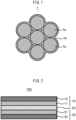
- an active material secondary particle 1 includes a plurality of negative electrode active material particles 1a and perfluoropolyether 1b.
- the plurality of negative electrode active material particles 1a are connected to each other via perfluoropolyether 1b.
- the active material secondary particle 1 of the present disclosure includes perfluoropolyether 1b together with a plurality of negative electrode active material particles 1a, and as shown in FIG. 1 , the plurality of negative electrode active material particles 1a can be connected to each other via perfluoropolyether 1b.
- voids can exist between the plurality of negative electrode active material particles 1a, or the voids can be filled with perfluoropolyether 1b.
- perfluoropolyether 1b When voids or perfluoropolyether 1b exist between the negative electrode active material particles 1a, even if the negative electrode active material particles 1a occlude carrier ions to expand, the expansion is absorbed by the voids or perfluoropolyether 1b, thus making it possible to mitigate the expansion of the secondary particle as a whole. In other words, the volume change of the secondary particle as a whole is likely to decrease.
- the active material secondary particle 1 includes perfluoropolyether 1b together with the negative electrode active material particles 1a, leading to a change in volume of the negative electrode active material particle 1a, the arrangement of the negative electrode active material particles 1a in the active material secondary particle 1 is likely to change smoothly via perfluoropolyether 1b. From this point of view, the volume change of the active material secondary particle 1 as a whole tends to decrease. In addition, smooth change in arrangement of the negative electrode active material particle 1a in the active material secondary particles 1 makes it difficult for local stress concentration to occur on the negative electrode active material particle 1a, thus making it easier to suppress cracking and crushing of the negative electrode active material particles 1a.
- the arrangement of the negative electrode active material particles 1a in the active material secondary particle 1 changes smoothly, thus making it possible to suppress cracking and crushing of the negative electrode active material particles 1a.
- stress concentration due to expansion and contraction of the negative electrode active material particles 1a is also suppressed, and from this point of view, cracking and crushing of the negative electrode active material particles 1a can also be suppressed.
- perfluoropolyether 1b is disposed in the vicinity of the negative electrode active material particles 1a even after formation of the secondary battery, and it is considered that the perfluoropolyether is less likely to inhibit ionic conduction (e.g., ionic conduction between solid electrolytes) or electronic conduction on the negative electrode of the secondary battery.
- ionic conduction e.g., ionic conduction between solid electrolytes
- electronic conduction e.g., ionic conduction between solid electrolytes
- the negative electrode active material particles 1a are particles made of a substance known as the negative electrode active material of the secondary battery. It is possible to employ, as the negative electrode active material, various materials wherein a potential at which they occlude/release predetermined carrier ions (e.g., lithium ions) (charge-discharge potential) is a lower potential than that of a positive electrode active material mentioned below.
- a potential at which they occlude/release predetermined carrier ions e.g., lithium ions
- charge-discharge potential is a lower potential than that of a positive electrode active material mentioned below.
- the negative electrode active material constituting the negative electrode active material particles 1a may contain at least one selected from silicon-based active materials such as Si, Si alloys and silicon oxide; carbon-based active materials such as graphite and hard carbon; various oxide-based active materials such as lithium titanate; metallic lithium and lithium alloys.
- silicon-based active materials such as Si, Si alloys and silicon oxide
- carbon-based active materials such as graphite and hard carbon
- various oxide-based active materials such as lithium titanate
- metallic lithium and lithium alloys metallic lithium and lithium alloys.
- the performance of the secondary battery is easily enhanced when the negative electrode active material is one or both of the silicon-based active material and the carbon-based active material.
- the negative electrode active material may be used alone, or two or more thereof may be used in combination. As mentioned above, it is easy for the technology of the present disclosure to suppress the volume change of the active material secondary particle 1 as a whole even if the volume change of the negative electrode active material particles 1a itself during charging and discharging is large.
- the technology of the present disclosure is also applicable to the case where the negative electrode active material particles 1a contains Si (e.g., silicon-based active materials mentioned above).
- Si e.g., silicon-based active materials mentioned above.
- the volume change of the negative electrode active material particles 1a containing Si due to occlusion and release of carrier ions, as mentioned above the volume change of the secondary particle as a whole is suppressed when the negative electrode active material particles 1a are converted into the secondary particle together with perfluoropolyether 1b.
- the negative electrode active material particles 1a contains Si its chemical composition is not particularly limited.
- the ratio of the Si element to all elements contained in the negative electrode active material particles 1a may be 50 mol% or more, 70 mol% or more, or 90 mol% or more.
- the negative electrode active material particles 1a may contain other elements, for example, alkali metal elements such as Li element and Na element.
- alkali metal elements such as Li element and Na element.
- the other element include at least one element selected from alkali metal elements such as Li element and Na element, Sn element, Fe element, Co element, Ni element, Ti element, Cr element, B element, P element and the like.
- the negative electrode active material particles 1a may also contain impurities such as oxides.
- the negative electrode active material particles 1a may be either amorphous or crystalline.
- the crystalline phase contained in the negative electrode active material particles 1a is not particularly limited.
- the negative electrode active material particles 1a may be either primary or secondary particles. That is, the active material secondary particle 1 may include a plurality of negative electrode active material particles 1a which are primary particles, a plurality of negative electrode active material particles 1a which are secondary particles, or a combination of negative electrode active material particles 1a which are primary particles, and negative electrode active material particles 1a which are secondary particles.
- the size of the negative electrode active material particles 1a is not particularly limited.
- the mean particle diameter of the negative electrode active material particles 1a may be 10 nm or more, 30 nm or more, 50 nm or more, 0.1 ⁇ m or more, or 0.2 ⁇ m or more, and may be 20.0 ⁇ m or less, 15.0 ⁇ m or less, 10.0 ⁇ m or less, 5.0 ⁇ m or less, 3.0 ⁇ m or less, 2.0 ⁇ m or less, or 1.0 ⁇ m or less.
- the mean particle diameter of the negative electrode active material particles 1a is 0.1 ⁇ m or more and 5.0 ⁇ m or less
- the mean particle diameter of the active material secondary particles 1 is 0.5 ⁇ m or more and 20.0 ⁇ m or less
- the mean particle diameter of the negative electrode active material particles 1a can be determined by observation using an electron microscope such as SEM, for example, it is determined as an average value of the maximum Feret diameter of each of a plurality of particles. The larger the number of samples, the better, and the number of samples is, for example, 20 or more, 50 or more, or 100 or more.
- the mean particle diameter of the negative electrode active material particles 1a can be appropriately adjusted, for example, by appropriately changing the production conditions or classifying the particles.
- the negative electrode active material particles 1a may have voids or may be porous. When the negative electrode active material particles 1a have voids, the voids can mitigate the expansion of the negative electrode active material particle 1a as a whole during charging. There is no particular limitation on the form of the voids in the negative electrode active material particles 1a.
- the negative electrode active material particles 1a may be particles containing nanoporous silicon. Nanoporous silicon refers to silicon in which a plurality of pores having a pore diameter on the nanometer order (less than 1,000 nm, and preferably 100 nm or less) are present.
- the negative electrode active material particles 1a may be porous silicon particles with pores having a diameter of 55 nm or less.
- Pores having a diameter of 55 nm or less are not easily collapsed by pressing.
- porous silicon particles with pores having a diameter of 55 nm or less easily maintain a porous state thereof after pressing.
- porous silicon particles (1 g) may contain 0.21 cc or more, 0.22 cc/g or more, or 0.23 cc/g or more of pores having a diameter of 55 nm or less, and may contain 0.30 cc/g or less, 0.28 cc/g or less, or 0.26 cc/g or less of pores having a diameter of 55 nm or less.
- the amount of pores having a diameter of 55 nm or less contained in porous silicon particles can be determined, for example, from the pore size distribution by the nitrogen gas adsorption method and DFT method.
- the porosity is not particularly limited.
- the porosity of the negative electrode active material particles 1a may be 1% or more, 5% or more, 10% or more, or 20% or more, and may be 80% or less, 70% or less, 60% or less, 50% or less, 40% or less, or 30% or less.
- the porosity of the negative electrode active material particles 1a can be determined, for example, by observation using a scanning electron microscope (SEM). The larger the number of samples, the better and is, for example, 100 or more.
- the porosity can be defined as the average value obtained from these samples.
- the number of negative electrode active material particles 1a included in one active material secondary particle 1 is not particularly limited. The number may be 2 or more, 5 or more, 10 or more, or 50 or more, and may be 1,000 or less, 500 or less, or 100 or less.
- the inclusion of perfluoropolyether 1b together with the negative electrode active material particles 1a mentioned above makes it easier to suppress the volume change of the active material secondary particle 1 as a whole during charging and discharging, and also makes it easier to suppress cracking and crushing of the negative electrode active material particles 1a.
- the perfluoropolyether 1b has an ether bond, it is considered to have high affinity to the surfaces of various battery materials, and for example, it is considered to easily stay appropriately between the negative electrode active material particles 1a. This can, for example, impart lubricity between the negative electrode active material particles 1a.
- the perfluoropolyether 1b has perfluoropolyether chains, which can also impart lubricity between negative electrode active material particles 1a.
- the perfluoropolyether 1b may be those represented by the following formula (1): E 1 -Rf 1 -R F -O-Rf 2 -E 2 (1) wherein, in formula (1),
- Rfi and Rf 2 are each independently a C1-16 divalent alkylene group which may be substituted with one or more fluorine atoms.
- C1-16 divalent alkylene group in the C1-16 divalent alkylene group which may be substituted with one or more fluorine atoms, may be linear or branched, and may be preferably a linear or branched C1-6 alkylalkylene group, especially a C1-3 alkylene group, and more preferably linear C1-6 alkylene group, especially a C1-3 alkylene group.
- C1-16 divalent alkylene in the C1-16 divalent alkylene group which may be substituted with one or more fluorine atoms, may be linear or branched, and may be preferably a linear or branched C1-6 fluoroalkylene group, especially a C1-3 fluoroalkylene group, specifically may be -CF 2 CH 2 - and -CF 2 CF 2 CH 2 -, and more preferably a linear C1-6 perfluoroalkylene group, especially a C1-3 perluoroalkylene group, specifically may be a group selected from the group consisting of -CF 2 -, -CF 2 CF 2 - and -CF 2 CF 2 CF 2 -.
- E 1 and E 2 are each independently a monovalent group selected from the group consisting of a fluorine group, a hydrogen group, a hydroxyl group, an aldehyde group, a carboxylic acid group, a C1-10 alkyl ester group, an amide group which may have one or more substituents, and an amino group which may have one or more substituents.
- the perfluoropolyether 1b has low reactivity with a sulfide solid electrolyte mentioned below. Therefore, even when the perfluoropolyether 1b is in contact with the sulfide solid electrolyte, deterioration of the ionic conductivity due to alteration or degradation of the sulfide solid electrolyte is unlikely to occur. In particular, when the perfluoropolyether 1b has a nonpolar group as a terminal group, the reaction between the perfluoropolyether 1b and the sulfide solid electrolyte is further suppressed and higher effect can be expected.
- E 1 and E 2 are each independently a fluorine group, preferably.
- E 1 -Rf 1 and E 2 -Rf 2 may be each independently a group selected from the group consisting of -CF 3 , -CF 2 CF 3 and -CF 2 CF 2 CF 3 .
- R F is each independently in each occurrence a divalent fluoropolyether group.
- R F is preferably a group represented by the formula (2): -(OC 6 F 12 ) a -(OC 5 F 10 ) b -(OC 4 F 8 ) c -(OC 3 R Fa 6 ) d -(OC 2 F 4 ) e -(OCF 2 ) f - (2) wherein, in the formula (2):
- R Fa is preferably a hydrogen atom or a fluorine atom, and more preferably a fluorine atom.
- a, b, c, d, e and f may be each independently an integer of 0 to 100.
- the sum of a, b, c, d, e and f is preferably 5 or more, and more preferably 10 or more, and may, for example, 15 or more, or 20 or more.
- the sum of a, b, c, d, e and f is preferably 200 or less, more preferably 100 or less, and still more preferably 60 or less, and may be, for example, 50 or less, or 30 or less.
- repeating units may be linear or branched.
- -(OC 6 F 12 )- may be any of -(OCF 2 CF 2 CF 2 CF 2 CF 2 CF 2 )-, -(OCF(CF 3 )CF 2 CF 2 CF 2 )-, - (OCF 2 CF(CF 3 )CF 2 CF 2 CF 2 )-, -(OCF 2 CF 2 CF(CF 3 )CF 2 CF 2 )-, -(OCF 2 CF 2 CF 2 CF(CF 3 )CF 2 )- and - (OCF 2 CF 2 CF 2 CF(CF 3 ))-.
- -(OC 5 F 10 )- may be any of -(OCF 2 CF 2 CF 2 CF 2 CF 2 )-, -(OCF(CF 3 )CF 2 CF 2 CF 2 )-, - (OCF 2 CF(CF 3 )CF 2 CF 2 )-, -(OCF 2 CF 2 CF(CF 3 )CF 2 )- and -(OCF 2 CF 2 CF 2 CF(CF 3 ))-.
- -(OC 4 F 8 )- may be any of -(OCF 2 CF 2 CF 2 CF 2 )-, -(OCF(CF 3 )CF 2 CF 2 )-, -(OCF 2 CF(CF 3 )CF 2 )-, - (OCF 2 CF 2 CF(CF 3 ))-, -(OC(CF 3 ) 2 CF 2 )-, -(OCF 2 C(CF 3 ) 2 )-, -(OCF(CF 3 )CF(CF 3 ))-, - (OCF(C 2 F 5 )CF 2 )- and -(OCF 2 CF(C 2 F 5 ))-.
- -(OC 3 F 6 )- (i.e., when, in the formula (2), R Fa is a fluorine atom) may be any of -(OCF 2 CF 2 CF 2 )-, -(OCF(CF 3 )CF 2 )- and -(OCF 2 CF(CF 3 ))-.
- -(OC 2 F 4 )- may be any of -(OCF 2 CF 2 )- and -(OCF(CF 3 ))-.
- R F may be each independently in each occurrence a group represented by any one of the following formulas (2-1) to (2-5): -(OC 3 F 6 ) d -(OC 2 F 4 ) e - (2-1) wherein, in the formula (2-1),
- d is preferably 5 to 200, more preferably 10 to 100, and still more preferably 15 to 50, and is, for example, an integer of 25 to 35.
- the formula (2-1) is preferably a group represented by -(OCF 2 CF 2 CF 2 ) d - or -(OCF(CF 3 )CF 2 ) d -, and more preferably a group represented by -(OCF 2 CF 2 CF 2 ) d -.
- e is 0. In another aspect, e is 1.
- e and f are each independently, preferably 5 to 200, and more preferably an integer of 10 to 200.
- the sum of c, d, e and f is preferably 5 or more, and more preferably 10 or more, and may be, for example, 15 or more, or 20 or more.
- the formula (2-2) is preferably a group represented by -(OCF 2 CF 2 CF 2 CF 2 ) c -(OCF 2 CF 2 CF 2 ) d -(OCF 2 CF 2 ) e -(OCF 2 )f-.
- the formula (2-2) may be a group represented by -(OC 2 F 4 ) e -(OCF 2 )f-.
- R 6 is preferably OC 2 F 4 .
- R 7 is preferably a group selected from OC 2 F 4 , OC 3 F 6 and OC 4 F 8 , or a combination of two or three groups selected independently from these groups, and more preferably a group selected from OC 3 F 6 and OC 4 F 8 Examples of the combination of two or three groups selected independently from OC 2 F 4 , OC 3 F 6 and OC 4 F 8 include, but are not particularly limited to, OC 2 F 4 OC 3 F 6 -, -OC 2 F 4 OC 4 F 8 -, - OC 3 F 6 OC 2 F 4 -, -OC 3 F 6 OC 3 F 6 -, -OC 3 F 6 OC 4 F 8 -, -OC 4 F 8 OC 4 F 8 -, -OC 4 F 8 OC 3 F 6 -, -OC 4 F 8 OC 3 F 6 -, -OC 4 F 8 OC 3 F 6 -, -OC 4 F 8 OC 3 F
- g is preferably an integer of 3 or more, and more preferably 5 or more. g is preferably an integer of 50 or less.
- OC 2 F 4 , OC 3 F 6 , OC 4 F 8 , OC 5 F 10 and OC 6 F 12 may be either linear or branched, and preferably linear.
- the formula (2-3) is preferably -(OC 2 F 4 -OC 3 F 6 ) g - or -(OC 2 F 4 -OC 4 F 8 ) g -.
- e is preferably an integer of 1 or more and 100 or less, and more preferably 5 or more and 100 or less.
- the sum of a, b, c, d, e and f is preferably 5 or more, and more preferably 10 or more, and is, for example, 10 or more and 100 or less.
- f is preferably an integer of 1 or more and 100 or less, and more preferably 5 or more and 100 or less.
- the sum of a, b, c, d, e and f is preferably 5 or more, and more preferably 10 or more, and is, for example, 10 or more and 100 or less.
- the above R F is a group represented by the above formula (2-1).
- the above R F is a group represented by the above formula (2-2).
- the above R F is a group represented by the above formula (2-3).
- the above R F is a group represented by the above formula (2-4).
- the above R F is a group represented by the above formula (2-5).
- the ratio of e to f may be 0.5 to 4, preferably 0.6 to 3, more preferably 0.7 to 2, and still more preferably 0.8 to 1.4.
- e/f ratio the ratio of e to f
- the lubricity and the chemical stability are further improved.
- the smaller the e/f ratio the more the lubricity is improved.
- the stability of the compound can be further enhanced.
- the higher the e/f ratio the more the stability of the fluoropolyether structure is improved. In this case, the value off is preferably 0.8 or more.
- R F may be a group represented by the following formula (2-6): -(OCF 2 CF 2 CF 2 ) a -(OCF(CF 3 )CF 2 ) b -(OCF 2 CF(CF 3 )) c -(OCF 2 CF 2 ) d -(OCF(CF 3 )) e -(OCF 2 ) f - (2-6) wherein, in the formula (2-6),
- R F may be a group represented by the following formula (2-7): -(OCF 2 CF 2 ) d -(OCF(CF 3 )) e -(OCF 2 ) f - (2-7) wherein, in the formula (2-7),
- the ratio of d to f may be 0.5 to 4, preferably 0.6 to 3, more preferably 0.7 to 2, and still more preferably 0.8 to 1.4.
- d/f ratio the ratio of d to f
- the lubricity and the chemical stability are further improved.
- the smaller the d/f ratio the more the lubricity is improved.
- the stability of the compound can be further enhanced.
- the higher the d/f ratio the more the stability of the fluoropolyether structure is improved.
- the value of f is preferably 0.8 or more.
- the number-average molecular weight of the R F moiety is not particularly limited, but is, for example, 500 to 30,000, preferably 1,500 to 30,000, and more preferably 2,000 to 10,000.
- the number-average molecular weight of R F is the value measured by 19 F-NMR.
- the viscosity of the perfluoropolyether 1b is not particularly limited. In particular, when the viscosity of perfluoropolyether 1b at 25°C is 1 mPa ⁇ s or more and 5,000 mPa ⁇ s or less, especially 5 mPa ⁇ s or more and 3,000 mPa ⁇ s or less, the perfluoropolyether 1b can easily stay in the active material secondary particles 1, and higher lubricating effect is easily exerted in the active material secondary particles 1.
- the viscosity may be 5 mPa ⁇ s or more and 1,000 mPa ⁇ s or less.
- the viscosity of the perfluoropolyether 1b is the viscosity at 25°C using a B-type viscometer and can be measured in accordance with JIS K7117-1:1999.
- the volume ratio of the negative electrode active material particles 1a and the perfluoropolyether 1b in the active material secondary particles 1 is not particularly limited, but may be such that it can maintain a certain shape as the active material secondary particle 1.
- the volume ratio of the perfluoropolyether 1b to the total of the negative electrode active material particles 1a and the perfluoropolyether 1b is 1% by volume or more and 50% by volume or less, especially 2% by volume or more and 30% by volume or less, it is easy to obtain the active material secondary particle 1 which has a shape maintained more appropriately as the active material secondary particle 1, and is more excellent in handleability.
- the volume ratio of the negative electrode active material particles 1a and the perfluoropolyether 1b in the active material secondary particle 1 can be measured, for example, as follows. That is, the volume of the active material secondary particles 1 as a whole is measured using an optical microscope or SEM.
- the volume of the perfluoropolyether 1b is specified in such a manner that the active secondary particles 1 are washed with a solvent (which can dissolve the perfluoropolyether 1b, but does not dissolve other negative electrode active material particles 1a) and the filtrate containing perfluoropolyether 1b dissolved therein is collected by suction filtration, etc., followed by analysis of the collected solvent by GC-MS.
- the solvent may be extracted by distillation and then the volume of the perfluoropolyether 1b may be directly measured. This makes it possible to calculate the volume ratio of the perfluoropolyether 1b and the volume ratio of the negative electrode active material particles 1a in the volume of the active material secondary particles 1 measured in advance.
- the mass ratio of the negative electrode active material particles 1a and the perfluoropolyether 1b in the active material secondary particle 1 is not particularly limited, but may be such that it can maintain a certain shape as the active material secondary particle 1.
- the active material secondary particle 1 contains the perfluoropolyether 1b in the amount of 1 part by mass or more and 50 parts by mass or less, especially 10 parts by mass or more and 40 parts by mass or less, relative to 100 parts by mass of the negative electrode active material particles 1a, it is easy to obtain the active material secondary particle 1 which has a shape maintained more appropriately as the negative electrode secondary material particle 1, and is more excellent in handleability.
- the active material secondary particle 1 may or may not contain any sub-components together with the negative electrode active material particles 1a and the perfluoropolyether 1b.
- the active material secondary particle 1 may contain, for example, 90% by mass or more and 100% by mass or less, 95% by mass or more and 100% by mass or less, or 99% by mass or more and 100% by mass or less in total of the negative electrode active material particles 1a and the perfluoropolyether 1b.
- the active material secondary particle 1 may be substantially composed only of the negative electrode active material particles 1a and the perfluoropolyether 1b.
- the active material secondary particle 1 may be free of a solid electrolyte, a conductive aid and a binder.
- the mean particle diameter of the active material secondary particles 1 is not particularly limited.
- the mean particle diameter of the active material secondary particles 1 may be 50 nm or more, 0.1 ⁇ m or more, 0.5 ⁇ m or more, 1.0 ⁇ m or more, or 2.0 ⁇ m or more, and may be 80.0 ⁇ m or less, 60.0 ⁇ m or less, 40.0 ⁇ m or less, 20.0 ⁇ m or less, or 15.0 ⁇ m or less.
- the mean particle diameter of the negative electrode active material particles 1a is 0.1 ⁇ m or more and 5.0 ⁇ m or less
- the mean particle diameter of the active material secondary particles 1 is 0.5 ⁇ m or more and 20.0 ⁇ m or less
- the negative electrode mixture can constitute the negative electrode active material layer mentioned below.
- the negative electrode mixture may include at least the active material secondary particles 1, and a solid electrolyte.
- the negative electrode mixture may include at least the active material secondary particles 1, a solid electrolyte, and at least one of a conductive aid and a binder, and also may include at least the active material secondary particles 1, a solid electrolyte, a conductive aid, and a binder.
- the negative electrode mixture may also contain various additives and the like.
- the negative electrode mixture may or may not contain perfluoropolyether separately from the active material secondary particles 1.
- the content of each component in the negative electrode mixture may be determined according to the desired battery performance.
- the content of the active material secondary particles 1 may be 40% by mass or more, 50% by mass or more, 60% by mass or more, or 70% by mass or more, and may be less than 100%, or 90% by mass or less, based on 100% by mass of the entire negative electrode mixture.
- the content of the solid electrolyte may be more than 0% by mass or 10% by mass or more, and may be 60% by mass or less, 50% by mass or less, 40% by mass or less, or 30% by mass or less, based on 100% by mass of the entire negative electrode mixture.
- the content of the perfluoropolyether 1b constituting the active material secondary particles 1 may be 90% by mass or more, 95% by mass or more, or 99% by mass or more, and may be 100% by mass or less.
- the negative electrode mixture includes the active material secondary particles 1.
- the negative electrode mixture may also contain other negative electrode active materials independent of the active material secondary particles 1. However, it is considered that the smaller the content of other active materials, the more the effect due to the technology of the present disclosure is enhanced. For example, when the amount of the entire negative electrode active material contained in the negative electrode mixture is 100% by mass, the negative electrode active material particles 1a constituting the active material secondary particles 1 may account for 90% by mass or more, 95% by mass or more, or 99% by mass or more, and 100% by mass or less.
- any known solid electrolyte for secondary batteries may be used.
- the solid electrolyte may be either an inorganic solid electrolyte or an organic polymer electrolyte.
- the inorganic solid electrolyte has excellent ion conductivity and heat resistance.
- Examples of the inorganic solid electrolyte include oxide solid electrolytes and sulfide solid electrolytes.
- sulfide solid electrolytes especially sulfide solid electrolytes containing at least Li, S and P as constituent elements, have particularly high performance.
- Solid electrolytes may be either amorphous or crystalline.
- the solid electrolyte may also be particulate.
- the mean particle diameter (D50) of the solid electrolyte may be, for example, 10 nm or more and 10 ⁇ m or less.
- the mean particle diameter D50 in the present application is a particle diameter (median diameter) at a cumulative value of 50% in a particle size distribution in terms of volume by a laser diffraction scattering method.
- the ionic conductivity of the solid electrolyte at 25°C may be, for example, 1 ⁇ 10 -4 S/cm or more, or 1 ⁇ 10 -3 S/cm or more.
- the solid electrolyte may be used alone, or two or more thereof may be used in combination.
- the oxide solid electrolyte may be one or more selected from lithium lanthanum zirconate, LiPON, Li 1+X Al X Ge 2-X (PO 4 ) 3 , Li-SiO-based glass, Li-Al-S-O-based glass and the like.
- the sulfide solid electrolyte may be a glass-based sulfide solid electrolyte (sulfide glass), a glassceramics-based sulfide solid electrolyte, or a crystal-based sulfide solid electrolyte.
- Sulfide glass is amorphous.
- the sulfide glass may have a glass transition temperature (Tg).
- Tg glass transition temperature
- examples of the crystalline phase include a Thio-LISICON-type crystalline phase, an LGPS-type crystalline phase, and an argyrodite-type crystalline phase.
- the sulfide solid electrolyte may contain, for example, Li element, X element (wherein X is at least one of P, As, Sb, Si, Ge, Sn, B, Al, Ga and In), and S element.
- the sulfide solid electrolyte may further contain at least one of O element and halogen element.
- the sulfide solid electrolyte may also contain S element as a major component of the anion element.
- the sulfide solid electrolyte may be at least one selected from, for example, Li 2 S-P 2 S 5 , Li 2 S-P 2 S 5 -LiI, Li 2 S-P 2 S 5 -GeS 2 , Li 2 S-P 2 S 5 -Li 2 O, Li 2 S-P 2 S 5 -Li 2 O-LiI, Li 2 S-P 2 S 5 -LiI-LiBr, Li 2 S-SiS 2 , Li 2 S-SiS 2 -LiI, Li 2 S-SiS 2 -LiBr, Li 2 S-SiS 2 -LiCl, Li 2 S-SiS 2 -B 2 S 3 -LiI, Li 2 S-SiS 2 -P 2 S 5 -LiI, Li 2 S-B 2 S 3 , Li 2 S-P 2 S 5 -ZmSn (in which m and n are a positive number, and Z is any one of Ge
- the composition of the sulfide solid electrolyte is not particularly limited, but includes, for example, xLi 2 S ⁇ (100-x)P 2 S 5 (70 ⁇ x ⁇ 80), yLiI ⁇ zLiBr ⁇ (100-y-z)(xLi 2 S ⁇ (1-x)P 2 S 5 ) (0.7 ⁇ x ⁇ 0.8, 0 ⁇ y ⁇ 30, 0 ⁇ z ⁇ 30) and the like.
- the sulfide solid electrolyte may have the composition represented by the general formula: Li 4-x Ge 1-x P x S 4 (0 ⁇ x ⁇ 1).
- At least a part of Ge may be substituted with at least one of Sb, Si, Sn, B, Al, Ga, In, Ti, Zr, V and Nb.
- at least a portion of P may be substituted with at least one of Sb, Si, Sn, B, Al, Ga, In, Ti, Zr, V and Nb.
- a part of Li may be substituted with at least one of Na, K, Mg, Ca and Zn.
- a portion of S may be substituted with a halogen (at least one of F, Cl, Br and I).
- the sulfide solid electrolyte may have the composition represented by Li 7-a PS 6-a X a (X is at least one of Cl, Br and I, and a is a number of 0 or more and 2 or less).
- a may be 0, and may be more than 0.
- a may be 0.1 or more, and may be 0.5 or more, and may be 1 or more.
- a may be 1.8 or less, and may be 1.5 or less.
- Examples of the conductive aid which can be included in the negative electrode mixture include carbon materials such as vapor-phase-grown carbon fiber (VGCF), acetylene black (AB), Ketjen black (KB), carbon nanotube (CNT) and carbon nanofiber (CNF); and metallic materials such as nickel, aluminum and stainless steel.
- the conductive aid may be, for example, particulate or fibrous, and its size is not particularly limited.
- the conductive aid may be used alone, or two or more thereof may be used in combination.
- binder examples include butadiene rubber (BR)-based binders, butylene rubber (IIR)-based binders, acrylate-butadiene rubber (ABR)-based binders, styrene-butadiene-based rubber (SBR) binders, polyvinylidene fluoride (PVdF)-based binders, polytetrafluoroethylene (PTFE)-based binders, polyimide (PI)-based binders, polyacrylic acid-based binders and the like.
- the binder may be used alone, or a two or more thereof may be used in combination.
- a secondary battery 100 includes a negative electrode 10, an electrolyte layer 20 and a positive electrode 30.
- the negative electrode 10 includes the active material secondary particles 1.
- the negative electrode 10 may take various configurations as long as it includes the active material secondary particles 1 and can properly function as the negative electrode of the secondary battery. As shown in FIG. 2 , the negative electrode 10 may include a negative electrode active material layer 11 and a negative electrode current collector 12. In this case, the negative electrode active material layer 11 can include the active material secondary particles 1.
- the negative electrode active material layer 11 may be those composed of the negative electrode mixture material mentioned above.
- the shape of the negative electrode active material layer 11 is not particularly limited, and may be, for example, in the form of a sheet with almost flat surface.
- the thickness of the negative electrode active material layer 11 is not particularly limited, and may be, for example, 0.1 ⁇ m or more, 1 ⁇ m or more, or 10 ⁇ m or more, and may be 2 mm or less, 1 mm or less, or 500 ⁇ m or less.
- the negative electrode 10 may include a negative electrode current collector 12 which is in contact with the negative electrode active material layer 11. It is possible to employ, as the negative electrode current collector 12, any of common negative electrode current collectors for secondary batteries.
- the negative electrode current collector 12 may be in the form of foil, plate, mesh or perforated metal, and foamed body.
- the negative electrode current collector 12 may be a metal foil or metal mesh, or a carbon sheet. In particular, the metal foil is excellent in handleability or the like.
- the negative electrode current collector 12 may be composed of a plurality of foils or sheets. Examples of the metal constituting the negative electrode current collector 12 include Cu, Ni, Cr, Au, Pt, Ag, Al, Fe, Ti, Zn, Co, stainless steel and the like.
- the negative electrode current collector 12 may contain at least one metal selected from Cu, Ni and stainless steel.
- the negative electrode current collector 12 may have some coating layer on its surface for the purpose of adjusting the resistance or the like.
- the negative electrode current collector 12 may be a metal foil or base material on which the above metals are plated or vapor-deposited.
- the negative electrode current collector 12 is composed of a plurality of metal foils, it may have some layer between the plurality of metal foils.
- the thickness of the negative electrode current collector 12 is not particularly limited. For example, the thickness may be 0.1 ⁇ m or more, or 1 ⁇ m or more, and may be 1 mm or less, or 100 ⁇ m or less.
- An electrolyte layer 20 is disposed between a negative electrode 10 and a positive electrode 30, and can function as a separator.
- the electrolyte layer 20 contains at least an electrolyte and may optionally contain a binder or the like.
- the electrolyte layer 20 may further contain various additives and the like.
- the content of each component in the electrolyte layer 20 is not particularly limited and may be determined according to the desired battery performance.
- the shape of the electrolyte layer 20 is not particularly limited, and may be, for example, in the form of a sheet with almost flat surface.
- the thickness of the electrolyte layer 20 is not particularly limited, and may be, for example, 0.1 ⁇ m or more, or 1 ⁇ m or more, and may be 2 mm or less, or 1 mm or less.
- the electrolyte contained in the electrolyte layer 20 any known electrolytes for secondary batteries.
- the electrolyte layer 20 containing a solid electrolyte, especially a sulfide solid electrolyte, and more especially a sulfide solid electrolytes containing at least Li, S and P as constituent elements has high performance. Details of the solid electrolyte are described above.
- the type of the electrolyte contained in the electrolyte layer 20 may be the same as or different from the type of the electrolyte which can be contained in the negative electrode mixture.
- the electrolyte may be used alone, or two or more thereof may be used in combination.
- the binder which may be contained in the electrolyte layer 20 may be selected, for example, from those exemplified as binders which can be contained in the negative electrode mixture.
- the type of binder contained in the electrolyte layer 20 may be the same as or different from the type of the binder which can be contained in the negative electrode mixture.
- the binder may be used alone, or two or more thereof may be used in combination.
- the positive electrode 30 may take various configurations as long as it can properly function as the negative electrode of the secondary battery. As shown in FIG. 2 , the positive electrode 30 may include a positive electrode active material layer 31 and a positive electrode current collector 32.
- the positive electrode active material layer 31 contains at least a positive electrode active material.
- the positive electrode active material layer 31 may optionally contain an electrolyte, a conductive aid and a binder. Furthermore, the positive electrode active material layer 31 may contain various additives and the like.
- the content of each component in the positive electrode active material layer 31 may be determined according to the desired battery performance. For example, the content of the positive electrode active material may be 40% by mass or more, 50% by mass or more, 60% by mass or more, or 70% by mass or more, and may be 100% or less, 95% by mass or less, or 90% by mass or less, based on 100% by mass of the total solid content of the positive electrode active material layer 31.
- 85% by volume or more, 90% by volume or more, or 95% by volume or more in total of the positive electrode active material and, optionally, an electrolyte, a conductive aid and a binder may be contained based on 100% by volume of the entire positive electrode active material layer 31, the balance being voids or other components.
- the shape of the positive electrode active material layer 31 is not particularly limited, and may be, for example, in the form of a sheet with almost flat surface.
- the thickness of the positive electrode active material layer 31 is not particularly limited, and may be, for example, 0.1 ⁇ m or more, 1 ⁇ m or more, or 10 ⁇ m or more, and may be 2 mm or less, 1 mm or less, or 500 ⁇ m or less.
- any known positive electrode active materials for secondary batteries may be used.
- known active materials it is possible to use, as the positive electrode active material, a material wherein a potential at which it occludes/releases predetermined carrier ions (e.g., lithium ions) (charge-discharge potential) is relatively high, and to use, as the negative electrode active material, a material wherein a potential at which it occludes/releases predetermined carrier ions is relatively low.
- the positive electrode active material may be, for example, at least one selected from various lithium-containing compounds, elemental sulfur and sulfur compounds and the like.
- Lithium-containing compounds as positive electrode active materials may be various lithium-containing oxides such as lithium cobaltate, lithium nickelate, Li 1 ⁇ Ni 1/3 Co 1/3 Mn 1/3 O 2 ⁇ , lithium manganate and spine-based lithium compounds (different element-substituted Li-Mn spinel with the composition represented by Li 1+x Mn 2-x-y M y O 4 (M is one or more selected from Al, Mg, Co, Fe, Ni and Zn), etc.), lithium titanate and lithium metal phosphate (LiMPO 4 , etc., where M is one or more selected from Fe, Mn, Co and Ni).
- lithium cobaltate lithium nickelate
- lithium manganate and spine-based lithium compounds different element-substituted Li-Mn spinel with the composition represented by Li 1+x Mn 2-x-y M y O 4 (M is one or more selected from Al, Mg, Co, Fe, Ni and Zn), etc.
- LiMPO 4 lithium titanate
- the positive electrode active material contains, as a constituent element, a lithium-containing oxide including at least Li, at least one of Ni, Co and Mn, and O, the performance of the secondary battery can be easily more enhanced.
- the positive electrode active material may be used alone, or two or more thereof may be used in combination.
- the shape of the positive electrode active material may be any shape commonly used as the positive electrode active material of the secondary battery.
- the positive electrode active material may be particulate.
- the positive electrode active material may have voids, for example, it may be either porous or hollow.
- the positive electrode active material may be either a primary particle or a secondary particle in which a plurality of primary particles are agglomerated.
- the mean particle diameter D50 of the positive electrode active material may be, for example, 1 nm or more, 5 nm or more, or 10 nm or more, and may be 500 ⁇ m or less, 100 ⁇ m or less, 50 ⁇ m or less, or 30 ⁇ m or less.
- the mean particle diameter D50 of the positive electrode active material is a particle diameter (median diameter) at a cumulative value of 50% in a particle size distribution in terms of volume by a laser diffraction scattering method.
- a protective layer containing an ionic conductive oxide may be formed on the surface of the positive electrode active material. This makes it easier to suppress the reaction between the positive electrode active material and sulfide (e.g., sulfide solid electrolyte).
- ionic conductive oxides include Li 3 BO 3 , LiBOz, Li 2 CO 3 , LiAlOz, Li 4 SiO 4 , Li 2 SiO 3 , Li 3 PO 4 , Li 2 SO 4 , Li 2 TiO 3 , Li 4 Ti 5 O 12 , Li 2 Ti 2 O 5 , Li 2 ZrO 3 , LiNbO 3 , Li 2 MoO 4 , Li 2 WO 4 and the like.
- the ionic conductive oxide may be those in which some elements are substituted with a doping element such as P or B.
- the coverage ratio (area ratio) of the protective layer to the surface of the positive electrode active material may be, for example, 70% or more, 80% or more, or 90% or more.
- the thickness of the protective layer may be, for example, 0.1 nm or more, 1 nm or more, and may be 100 nm or less, or 20 nm or less.
- the electrolyte which can be contained in the positive electrode active material layer 31 may be a solid electrolyte, a liquid electrolyte (electrolyte solution), or a combination thereof.
- the positive electrode active material layer 31 may contain a solid electrolyte, especially a sulfide solid electrolyte, and more especially a sulfide solid electrolyte containing Li, S and P as constituent elements.
- the conductive aid which can be contained in the positive electrode active material layer 31 may be appropriately selected from those exemplified as the conductive aid which can be contained in the negative electrode mixture.
- the type of the conductive aid contained in the positive electrode active material layer 31 may be the same as or different from the type of conductive aid which can be contained in the negative electrode mixture.
- the conductive aid may be used alone, or two or more thereof may be used in combination.
- the binder which can be contained in the positive electrode active material layer 31 may be selected from those exemplified as the binder which can be contained in the negative electrode mixture.
- the type of binder contained in the positive electrode active material layer 31 may be the same as or different from the type of binder which can be contained in the negative electrode mixture.
- the binder may be used alone, or two or more thereof may be used in combination.
- the negative electrode 30 may include a positive electrode current collector 32 which is in contact with the positive electrode active material layer 31. It is possible to employ, as the positive electrode current collector 32, any of common positive electrode current collectors for secondary batteries.
- the positive electrode current collector 32 may be in the form of foil, plate, mesh or perforated metal, and foamed body.
- the positive electrode current collector 32 may be composed of a metal foil or metal mesh. In particular, the metal foil is excellent in handleability or the like.
- the positive electrode current collector 32 may be composed of a plurality of foils. Examples of the metal constituting the positive electrode current collector 32 include Cu, Ni, Cr, Au, Pt, Ag, Al, Fe, Ti, Zn, Co, stainless steel and the like.
- the positive electrode current collector 32 may contain Al.
- the positive electrode current collector 32 may have some coating layer on its surface for the purpose of adjusting the resistance or the like.
- the positive electrode current collector 32 may be a metal foil or base material on which the above metals are plated or vapor-deposited. When the positive electrode current collector 32 is composed of a plurality of metal foils, it may have some layer between the plurality of metal foils.
- the thickness of the positive electrode current collector 32 is not particularly limited. For example, the thickness may be 0.1 ⁇ m or more, or 1 ⁇ m or more, and may be 1 mm or less, or 100 ⁇ m or less.
- the secondary battery 100 may be those in which each of the above components is housed inside an exterior body. It is possible to employ, as the exterior body, any known exterior bodies for batteries. A plurality of secondary batteries 100 may be optionally electrically connected and optionally stacked to form a battery assembly. In this case, the battery assembly may be housed inside a known battery casing.
- the secondary battery 100 may include other obvious components such as necessary terminals. Examples of the shape of the secondary battery 100 include coin-shape, laminated shape, cylindrical shape and square shape.
- the technology of the present disclosure also has an aspect of a method for producing active material secondary particles.
- the method for producing active material secondary particles 1 comprises mixing a plurality of negative electrode active material particles 1a and perfluoropolyether 1b to bond the plurality of negative electrode active material particles 1a to each other via the perfluoropolyether 1b.
- the mixing of the negative electrode active material particles 1a and the perfluoropolyether 1b can be carried out using a known mixing device or the like.
- the mixing conditions are not particularly limited, as long as the conditions are such that the negative electrode active material particles 1a and the perfluoropolyether 1b can be converted into secondary particles.
- the mixing ratio volume ratio and mass ratio
- the technology of the present disclosure also has an aspect as a method for producing a negative electrode mixture.
- the method for producing a negative electrode mixture comprises mixing the active material secondary particles 1 and a solid electrolyte.
- the negative electrode mixture may include, in addition to the active material secondary particles 1 and the solid electrolyte, a conductive aid, a binder and various additives.
- the method for producing a negative electrode mixture may include mixing the active material secondary particles 1, a solid electrolyte, and at least one of a conductive aid and a binder, or may include mixing the active material secondary particles 1, a solid electrolyte, a conductive aid and a binder.
- the mixing of the active material secondary particles 1 with the solid electrolyte can be carried out using a known mixing device or the like.
- the mixing conditions are not particularly limited, as long as the conditions are such that each component can be uniformly mixed.
- the types and mixing ratios of each component are also as mentioned above.
- the technology of the present disclosure also has an aspect of a method for producing a secondary battery.
- the secondary battery 100 can be produced by applying known methods. For example, it can be produced as follows.
- the method for producing a secondary battery 100 is not limited to the following method and, for example, each layer may be formed by dry molding or the like.
- the technology of the present disclosure also has an aspect as a method for improving the cycle characteristics of a secondary battery. That is, the method of the present disclosure is characterized in that the cycle characteristics of a secondary battery are improved by employing the active material secondary particles 1 in the negative electrode of the secondary battery.
- the details of the configurations of the secondary battery and the active material secondary particles are as mentioned above.
- the secondary battery of the present disclosure has excellent cycle characteristics and low resistance.
- Such secondary battery can be suitably used, for example, in at least one type of vehicle selected from hybrid electric vehicles (HEV), plug-in hybrid electric vehicles (PHEV) and battery electric vehicles (BEV). That is, the technology of the present disclosure also has an aspect as a vehicle including a secondary battery, the secondary battery including a negative electrode, an electrolyte layer and a positive electrode, the negative electrode including the active material secondary particles 1. Details of the configuration of the secondary battery are as mentioned above.
- the technology of the present disclosure may be applied not only to lithium-ion secondary batteries, but also to secondary batteries other than lithium-ion secondary batteries (e.g., sodium-ion secondary batteries). However, the technology of the present disclosure easily exert higher effect when applied to lithium-ion secondary batteries.
- a binder (PVdF), a conductive aid (VGCF), a sulfide solid electrolyte (LiI-LiBr-Li 2 S-P 2 S 5 ) and a positive electrode active material (LiNi 0.80 Co 0.15 Mn 0.05 O 2 ) were added in an organic solvent, followed by kneading with an ultrasonic homogenizer to obtain a positive electrode mixture slurry.
- the positive electrode mixture slurry thus obtained was coated on an Al foil and then dried to obtain a positive electrode for pressing.
- a negative electrode for pressing was fabricated for each of the following cases where perfluoropolyether (PFPE) was not included when fabricating a negative electrode mixture (Comparative Examples 1 and 2); negative electrode active material particles, a solid electrolyte and PFPE were not simultaneously mixed (Comparative Examples 3 and 4, when negative electrode active material particles and PFPE were not converted into secondary particles); and negative electrode active material particles and PFPE were converted into secondary particles in advance and the secondary particles were mixed with a solid electrolyte, etc. (Examples 1 and 2).
- PFPE perfluoropolyether
- a binder (PVdF), a conductive aid (VGCF), a sulfide solid electrolyte (LiI-LiBr-Li 2 S-P 2 S 5 ) and negative electrode active material particles (porous Si particles, mean particle diameter: 0.5 ⁇ m) were added in an organic solvent, followed by kneading with an ultrasonic homogenizer to obtain a negative electrode mixture slurry.
- the mixing ratio of the binder, the conductive aid, the solid sulfide electrolyte and the negative electrode active material particles included in the negative electrode mixture was 2.5:5:41:51.5 (binder:conductive aid:solid sulfide electrolyte: negative electrode active material particles) by mass.
- the negative electrode mixture slurry thus obtained was coated on a Cu foil and then dried to obtain a positive electrode for pressing.
- a binder (PVdF), a conductive aid (VGCF), a sulfide solid electrolyte (LiI-LiBr-Li 2 S-P 2 S 5 ), negative electrode active material particles (porous Si particles, mean particle size: 0.5 ⁇ m) and PFPE were added in an organic solvent, followed by kneading with an ultrasonic homogenizer to obtain a negative electrode mixture slurry.
- the mixing ratio of the binder, the conductive aid, the solid sulfide electrolyte, the negative electrode active material particles and PEFE included in the negative electrode mixture was 2:4:37:47.5:9.5 (binder:conductive aid: solid sulfide electrolyte: negative electrode active material particles:PEFE) by mass (so that 20 parts by mass of PFPE are included relative to 100 parts by mass of negative electrode active material particles in the negative electrode for pressing).
- the negative electrode mixture slurry thus obtained was coated on a Cu foil and then dried to obtain a positive electrode for pressing.
- Negative electrode active material particles (porous Si particles, mean particle size: 0.5 ⁇ m) and PFPE were mixed in a mortar to obtain active material secondary particles containing a plurality of negative electrode active material particles and PFPE.
- 20 parts of PFPE were mixed with 100 parts of the negative electrode active material.
- the volume ratio of the negative electrode active material particles to the total of the negative electrode active material particles and PFPE in the active material secondary particles was 81% by volume.
- the mean particle size of the active material secondary particles was 8 ⁇ m.
- a binder (PVdF), a conductive aid (VGCF), a sulfide solid electrolyte (LiI-LiBr-Li 2 S-P 2 S 5 ) and the active material secondary particles were added in an organic solvent, followed by kneading with an ultrasonic homogenizer to obtain a negative electrode mixture slurry.
- the mixing ratio of the binder, the conductive aid, the solid sulfide electrolyte and the active material secondary particles included in the negative electrode mixture was 2:4:37:57 (binder:conductive aid:solid sulfide electrolyte: active material secondary particles) by mass.
- the negative electrode mixture slurry thus obtained was coated on a Cu foil and then dried to obtain a negative electrode for pressing.
- the active material secondary particles contain 20 parts by mass of PFPE relative to 100 parts by mass of the negative electrode active material.
- the volume ratio of the negative electrode active material particles to the total of the negative electrode active material particles and PFPE in the active material secondary particles was 83% by volume.
- the mixing ratio of the binder, the conductive aid, the sulfide solid electrolyte and active material secondary particles included in the negative electrode mixture is the same as in Example 1.
- the mean particle size of the active material secondary particles was 10 ⁇ m.
- a binder (PVdF) and a sulfide solid electrolyte (LiI-LiBr-Li 2 S-P 2 S 5 ) were added in an organic solvent, followed by kneading with an ultrasonic homogenizer to obtain an electrolyte mixture slurry.
- the electrolyte mixture slurry thus obtained was applied on an Al foil and then dried to obtain an electrolyte layer for pressing.
- a positive electrode, a negative electrode and an electrolyte layer for pressing are respectively formed into strips, and the mixture surface of the positive electrode for pressing and the mixture surface of the electrolyte layer for pressing were overlapped, and after roll pressing at 165°C under pressure of 50 kN/cm, an Al foil of the electrolyte layer for pressing was peeled off to obtain a laminated body (A) comprising an Al foil, a positive electrode active material layer and an electrolyte layer.
- a laminated body (B) comprising a Cu foil, a negative electrode active material layer and an electrolyte layer.
- the laminated body (A) was punched in a diameter of 11.28 mm, and the laminated body (B) was punched in a diameter of 13.00 mm.
- the electrolyte layer was further transferred to the laminated body (B) using a uniaxial press, and then the laminated body (A) and the laminated body (B) are overlapped to obtain an electrode body having a configuration of Al foil/positive electrode active material layer/electrolyte layer/negative electrode active material layer/Cu foil.
- a battery for evaluation was fabricated by attaching a current extraction tab to each of the Al foil and Cu foil of the electrode body, and sealing in a laminated package using a vacuum sealer.
- the resistance of the evaluation battery fabricated as mentioned above was measured. Specifically, the voltage of the battery was adjusted to 3.7 V, and the resistance value (initial resistance) of the battery was calculated from the voltage drop after 5 seconds when discharging at a 5 C rate.
- Examples 1 and 2 it is considered that a plurality of negative electrode active material particles are connected to each other via perfluoropolyether, and voids exist between the plurality of negative electrode active material particles, or voids exist between the plurality of negative electrode active material particles or the voids are filled with perfluoropolyether ( FIG. 1 ).
- perfluoropolyether and voids exist between the negative electrode active material particles, even if the negative electrode active material particles expand during charging of the secondary battery, the amount of expansion of the secondary particles as a whole is considered to be mitigated. That is, it is considered that the volume change of the secondary particles as a whole decreases.
- Example 1 and 2 when the volume of the negative electrode active material particles changes, the arrangement of the negative electrode active material particles in the active material secondary particles changes smoothly via the perfluoropolyether, thereby, the volume change of the active material secondary particles as a whole is considered to decrease. Since the arrangement of the negative electrode active material particles in the active material secondary particles changes smoothly, local stress concentration on the negative electrode active material particles is less likely to occur, and thus cracking of the negative electrode active material particles is considered to be suppressed. In Examples 1 and 2, when the negative electrode is pressed, the arrangement of the negative electrode active material particles in the active material secondary particles changed smoothly via PFPE, and the filling rate of the negative electrode increases and crushing of negative electrode material particles is considered to be suppressed.
- Examples 1 and 2 by converting the negative electrode active material particles and PFPE into secondary particles in advance, even after the secondary battery is formed, PFPE is disposed only in the vicinity of the negative electrode active material particles, and it is considered that PFPE is less likely to inhibit ionic conduction (e.g., ionic conduction between solid electrolytes) or electronic conduction on the negative electrode of the secondary battery. It is considered that as a result of a complex combination of these effects, in Examples 1 and 2, the initial resistance of the secondary battery was significantly reduced and the cycle characteristics were significantly improved.
- ionic conduction e.g., ionic conduction between solid electrolytes
- PFPE having a specific chemical structure was exemplified in the above Examples, but the chemical structure of PFPE is not limited thereto. Further, the case where porous Si particles and graphite particles are used as negative electrode active material particles was exemplified in the above Examples, but the types of negative electrode active material particles are not limited thereto. Further, the composition of the mixture of the positive electrode, the electrolyte layer and the negative electrode is not limited to those mentioned above.
- the formation of a negative electrode mixture and a secondary battery using active material secondary particles including a plurality of negative electrode active material particles and perfluoropolyether makes it easier for the secondary battery to have low resistance and excellent cycle characteristics.
Landscapes
- Chemical & Material Sciences (AREA)
- Chemical Kinetics & Catalysis (AREA)
- General Chemical & Material Sciences (AREA)
- Electrochemistry (AREA)
- Engineering & Computer Science (AREA)
- Manufacturing & Machinery (AREA)
- Materials Engineering (AREA)
- Inorganic Chemistry (AREA)
- Organic Chemistry (AREA)
- Composite Materials (AREA)
- Physics & Mathematics (AREA)
- Condensed Matter Physics & Semiconductors (AREA)
- General Physics & Mathematics (AREA)
- Battery Electrode And Active Subsutance (AREA)
Abstract
Disclosed is new technology for reducing the resistance of a secondary battery and improving the cycle characteristics. In a negative electrode of the secondary battery, predetermined active material secondary particles are used. The active material secondary particles of the present disclosure comprise a plurality of negative electrode active material particles and perfluoropolyether.
Description
- The present application discloses active material secondary particles, a negative electrode mixture, a method for producing same, and a secondary battery.
-
PTL 1 discloses the use of predetermined porous silicon particles as a negative electrode active material to suppress an increase in constraining pressure of batteries during charging. PTL 2 discloses making a perfluoropolyether group-containing compound exist on the surface of electrodes to improve the shelf life of the electrodes. -
- [PTL 1]
JP 2020-170605 A - [PTL 2]
JP 2018-147887 A - A negative electrode of a secondary battery can be formed by pressing a negative electrode mixture containing a negative electrode active material. If the negative electrode mixture is pressed under high pressure to increase the filling ratio of the negative electrode leading to reduction in resistance of the negative electrode, the negative electrode active material may be crushed. Meanwhile, if the negative electrode mixture is pressed under low pressure to avoid crushing of the negative electrode active material, the filling ratio of the negative electrode decreases and the resistance of the negative electrode is likely to increase.
- During charging and discharging of the secondary battery, the negative electrode active material occludes or releases carrier ions, leading to a change in volume of the negative electrode active material. This volume change of the negative electrode active material may cause voids or cracks in the negative electrode of the secondary battery, resulting in deterioration of the cycle characteristics of the secondary battery.
- As mentioned above, in conventional secondary batteries, there is room for improvement with respect to the achievement of both reducing the resistance and improving the cycle characteristics.
- The present application discloses, as aforementioned solution to problem, the following plurality of aspects.
- Active material secondary particles comprising a plurality of negative electrode active material particles and perfluoropolyether.
- The active material secondary particles according to
aspect 1, wherein
the negative electrode active material particles contain Si. - The active material secondary particles according to
aspect 1 or 2, wherein
a volume ratio of the perfluoropolyether to the total of the negative electrode active material particles and the perfluoropolyether is 2% by volume or more and 30% by volume or less. - The active material secondary particles according to any one of
aspects 1 to 3, wherein the perfluoropolyether has a viscosity of 5 mPa•s or more and 3,000 mPa•s or less at 25°C. - The active material secondary particles according to any one of
aspects 1 to 4, wherein - the negative electrode active material particles have a mean particle diameter of 0. 1 µm or more and 5.0 µm or less, and
- the active material secondary particles have a mean particle diameter of 0.5 µm or more and 20.0 µm or less.
- A negative electrode mixture comprising at least the active material secondary particles according to any one of
aspects 1 to 5, and a solid electrolyte. - A method for producing active material secondary particles, the method comprising
mixing a plurality of negative electrode active material particles and perfluoropolyether to bond the plurality of negative electrode active material particles to each other via the perfluoropolyether. - A method for producing a negative electrode mixture, the method comprising
mixing the active material secondary particles according to any one ofaspects 1 to 5 and a solid electrolyte. - A secondary battery comprising a negative electrode, an electrolyte layer and a positive electrode, wherein
the negative electrode comprises the active material secondary particles according to any one ofaspects 1 to 5. - When a secondary battery is formed using active material secondary particles of the present disclosure, it becomes easier for the secondary battery to have low resistance and excellent cycle characteristics.
-
-
FIG. 1 schematically shows an example of a configuration of an active material secondary particle. -
FIG. 2 schematically shows an example of a configuration of a secondary battery. - Embodiments of the technology of the present disclosure will be described below, but the technology of the present disclosure is not limited to the following embodiments.
- As shown in
FIG. 1 , an active materialsecondary particle 1 according to one embodiment includes a plurality of negative electrodeactive material particles 1a andperfluoropolyether 1b. In the active materialsecondary particle 1, for example, as shown inFIG. 1 , the plurality of negative electrodeactive material particles 1a are connected to each other viaperfluoropolyether 1b. - During charging and discharging of a secondary battery, a negative electrode active material occludes or releases carrier ions, leading to a change in volume of the negative electrode active material. Excessive volume change of the negative electrode active material may cause voids or cracks in the negative electrode, which may adversely affect the cycle characteristics of the secondary battery. In contrast, as mentioned above, the active material
secondary particle 1 of the present disclosure includesperfluoropolyether 1b together with a plurality of negative electrodeactive material particles 1a, and as shown inFIG. 1 , the plurality of negative electrodeactive material particles 1a can be connected to each other viaperfluoropolyether 1b. In the active materialsecondary particle 1, voids can exist between the plurality of negative electrodeactive material particles 1a, or the voids can be filled withperfluoropolyether 1b. When voids orperfluoropolyether 1b exist between the negative electrodeactive material particles 1a, even if the negative electrodeactive material particles 1a occlude carrier ions to expand, the expansion is absorbed by the voids orperfluoropolyether 1b, thus making it possible to mitigate the expansion of the secondary particle as a whole. In other words, the volume change of the secondary particle as a whole is likely to decrease. When the active materialsecondary particle 1 includesperfluoropolyether 1b together with the negative electrodeactive material particles 1a, leading to a change in volume of the negative electrodeactive material particle 1a, the arrangement of the negative electrodeactive material particles 1a in the active materialsecondary particle 1 is likely to change smoothly viaperfluoropolyether 1b. From this point of view, the volume change of the active materialsecondary particle 1 as a whole tends to decrease. In addition, smooth change in arrangement of the negative electrodeactive material particle 1a in the active materialsecondary particles 1 makes it difficult for local stress concentration to occur on the negative electrodeactive material particle 1a, thus making it easier to suppress cracking and crushing of the negative electrodeactive material particles 1a. For example, even when pressure is applied to the active materialsecondary particle 1 by press forming, etc., the arrangement of the negative electrodeactive material particles 1a in the active materialsecondary particle 1 changes smoothly, thus making it possible to suppress cracking and crushing of the negative electrodeactive material particles 1a. Similarly, stress concentration due to expansion and contraction of the negative electrodeactive material particles 1a is also suppressed, and from this point of view, cracking and crushing of the negative electrodeactive material particles 1a can also be suppressed. Furthermore, by forming a secondary battery using the active materialsecondary particles 1,perfluoropolyether 1b is disposed in the vicinity of the negative electrodeactive material particles 1a even after formation of the secondary battery, and it is considered that the perfluoropolyether is less likely to inhibit ionic conduction (e.g., ionic conduction between solid electrolytes) or electronic conduction on the negative electrode of the secondary battery. Thus, the formation of a secondary battery with such active materialsecondary particles 1 makes it easier to improve the cycle characteristics of the secondary battery and to reduce the resistance. - The negative electrode
active material particles 1a are particles made of a substance known as the negative electrode active material of the secondary battery. It is possible to employ, as the negative electrode active material, various materials wherein a potential at which they occlude/release predetermined carrier ions (e.g., lithium ions) (charge-discharge potential) is a lower potential than that of a positive electrode active material mentioned below. - The negative electrode active material constituting the negative electrode
active material particles 1a may contain at least one selected from silicon-based active materials such as Si, Si alloys and silicon oxide; carbon-based active materials such as graphite and hard carbon; various oxide-based active materials such as lithium titanate; metallic lithium and lithium alloys. In particular, the performance of the secondary battery is easily enhanced when the negative electrode active material is one or both of the silicon-based active material and the carbon-based active material. The negative electrode active material may be used alone, or two or more thereof may be used in combination. As mentioned above, it is easy for the technology of the present disclosure to suppress the volume change of the active materialsecondary particle 1 as a whole even if the volume change of the negative electrodeactive material particles 1a itself during charging and discharging is large. In this regard, the technology of the present disclosure is also applicable to the case where the negative electrodeactive material particles 1a contains Si (e.g., silicon-based active materials mentioned above). In other words, although the volume change of the negative electrodeactive material particles 1a containing Si due to occlusion and release of carrier ions, as mentioned above, the volume change of the secondary particle as a whole is suppressed when the negative electrodeactive material particles 1a are converted into the secondary particle together withperfluoropolyether 1b. When the negative electrodeactive material particles 1a contains Si, its chemical composition is not particularly limited. For example, the ratio of the Si element to all elements contained in the negative electrodeactive material particles 1a may be 50 mol% or more, 70 mol% or more, or 90 mol% or more. In addition to the Si element, the negative electrodeactive material particles 1a may contain other elements, for example, alkali metal elements such as Li element and Na element. Examples of the other element include at least one element selected from alkali metal elements such as Li element and Na element, Sn element, Fe element, Co element, Ni element, Ti element, Cr element, B element, P element and the like. The negative electrodeactive material particles 1a may also contain impurities such as oxides. The negative electrodeactive material particles 1a may be either amorphous or crystalline. The crystalline phase contained in the negative electrodeactive material particles 1a is not particularly limited. - The negative electrode
active material particles 1a may be either primary or secondary particles. That is, the active materialsecondary particle 1 may include a plurality of negative electrodeactive material particles 1a which are primary particles, a plurality of negative electrodeactive material particles 1a which are secondary particles, or a combination of negative electrodeactive material particles 1a which are primary particles, and negative electrodeactive material particles 1a which are secondary particles. The size of the negative electrodeactive material particles 1a is not particularly limited. For example, the mean particle diameter of the negative electrodeactive material particles 1a may be 10 nm or more, 30 nm or more, 50 nm or more, 0.1 µm or more, or 0.2 µm or more, and may be 20.0 µm or less, 15.0 µm or less, 10.0 µm or less, 5.0 µm or less, 3.0 µm or less, 2.0 µm or less, or 1.0 µm or less. In particular, when the mean particle diameter of the negative electrodeactive material particles 1a is 0.1 µm or more and 5.0 µm or less, and the mean particle diameter of the active materialsecondary particles 1 is 0.5 µm or more and 20.0 µm or less, higher effect is easily obtained. The mean particle diameter of the negative electrodeactive material particles 1a can be determined by observation using an electron microscope such as SEM, for example, it is determined as an average value of the maximum Feret diameter of each of a plurality of particles. The larger the number of samples, the better, and the number of samples is, for example, 20 or more, 50 or more, or 100 or more. The mean particle diameter of the negative electrodeactive material particles 1a can be appropriately adjusted, for example, by appropriately changing the production conditions or classifying the particles. - The negative electrode
active material particles 1a may have voids or may be porous. When the negative electrodeactive material particles 1a have voids, the voids can mitigate the expansion of the negative electrodeactive material particle 1a as a whole during charging. There is no particular limitation on the form of the voids in the negative electrodeactive material particles 1a. The negative electrodeactive material particles 1a may be particles containing nanoporous silicon. Nanoporous silicon refers to silicon in which a plurality of pores having a pore diameter on the nanometer order (less than 1,000 nm, and preferably 100 nm or less) are present. The negative electrodeactive material particles 1a may be porous silicon particles with pores having a diameter of 55 nm or less. Pores having a diameter of 55 nm or less are not easily collapsed by pressing. In other words, porous silicon particles with pores having a diameter of 55 nm or less easily maintain a porous state thereof after pressing. For example, porous silicon particles (1 g) may contain 0.21 cc or more, 0.22 cc/g or more, or 0.23 cc/g or more of pores having a diameter of 55 nm or less, and may contain 0.30 cc/g or less, 0.28 cc/g or less, or 0.26 cc/g or less of pores having a diameter of 55 nm or less. The amount of pores having a diameter of 55 nm or less contained in porous silicon particles can be determined, for example, from the pore size distribution by the nitrogen gas adsorption method and DFT method. - When the negative electrode
active material particles 1a are porous, the porosity is not particularly limited. For example, the porosity of the negative electrodeactive material particles 1a may be 1% or more, 5% or more, 10% or more, or 20% or more, and may be 80% or less, 70% or less, 60% or less, 50% or less, 40% or less, or 30% or less. The porosity of the negative electrodeactive material particles 1a can be determined, for example, by observation using a scanning electron microscope (SEM). The larger the number of samples, the better and is, for example, 100 or more. The porosity can be defined as the average value obtained from these samples. - The number of negative electrode
active material particles 1a included in one active materialsecondary particle 1 is not particularly limited. The number may be 2 or more, 5 or more, 10 or more, or 50 or more, and may be 1,000 or less, 500 or less, or 100 or less. - As mentioned above, in the active material
secondary particle 1 of the present disclosure, the inclusion ofperfluoropolyether 1b together with the negative electrodeactive material particles 1a mentioned above makes it easier to suppress the volume change of the active materialsecondary particle 1 as a whole during charging and discharging, and also makes it easier to suppress cracking and crushing of the negative electrodeactive material particles 1a. Since theperfluoropolyether 1b has an ether bond, it is considered to have high affinity to the surfaces of various battery materials, and for example, it is considered to easily stay appropriately between the negative electrodeactive material particles 1a. This can, for example, impart lubricity between the negative electrodeactive material particles 1a. - The
perfluoropolyether 1b has perfluoropolyether chains, which can also impart lubricity between negative electrodeactive material particles 1a. For example, theperfluoropolyether 1b may be those represented by the following formula (1):
E1-Rf1-RF-O-Rf2-E2 (1)
wherein, in formula (1), - Rfi and Rf2 each independently represent a C1-16 divalent alkylene group which may be substituted with one or more fluorine atoms,
- E1 and E2 are each independently a monovalent group selected from the group consisting of a fluorine group, a hydrogen group, a hydroxyl group, an aldehyde group, a carboxylic acid group, a C1-10 alkyl ester group, an amide group which may have one or more substituents, and an amino group which may have one or more substituents, and
- RF is a divalent fluoropolyether group.
- In the formula (1), Rfi and Rf2 are each independently a C1-16 divalent alkylene group which may be substituted with one or more fluorine atoms.
- In one aspect, "C1-16 divalent alkylene group", in the C1-16 divalent alkylene group which may be substituted with one or more fluorine atoms, may be linear or branched, and may be preferably a linear or branched C1-6 alkylalkylene group, especially a C1-3 alkylene group, and more preferably linear C1-6 alkylene group, especially a C1-3 alkylene group.
- In one aspect, "C1-16 divalent alkylene", in the C1-16 divalent alkylene group which may be substituted with one or more fluorine atoms, may be linear or branched, and may be preferably a linear or branched C1-6 fluoroalkylene group, especially a C1-3 fluoroalkylene group, specifically may be -CF2CH2- and -CF2CF2CH2-, and more preferably a linear C1-6 perfluoroalkylene group, especially a C1-3 perluoroalkylene group, specifically may be a group selected from the group consisting of -CF2-, -CF2CF2- and -CF2CF2CF2-.
- In the formula (1), E1 and E2 are each independently a monovalent group selected from the group consisting of a fluorine group, a hydrogen group, a hydroxyl group, an aldehyde group, a carboxylic acid group, a C1-10 alkyl ester group, an amide group which may have one or more substituents, and an amino group which may have one or more substituents.
- The
perfluoropolyether 1b has low reactivity with a sulfide solid electrolyte mentioned below. Therefore, even when theperfluoropolyether 1b is in contact with the sulfide solid electrolyte, deterioration of the ionic conductivity due to alteration or degradation of the sulfide solid electrolyte is unlikely to occur. In particular, when theperfluoropolyether 1b has a nonpolar group as a terminal group, the reaction between theperfluoropolyether 1b and the sulfide solid electrolyte is further suppressed and higher effect can be expected. In this regard, E1 and E2 are each independently a fluorine group, preferably. In one aspect, E1-Rf1 and E2-Rf2 may be each independently a group selected from the group consisting of -CF3, -CF2CF3 and -CF2CF2CF3. - In the formula (1), RF is each independently in each occurrence a divalent fluoropolyether group.
- RF is preferably a group represented by the formula (2):
-(OC6F12)a-(OC5F10)b-(OC4F8)c-(OC3RFa 6)d-(OC2F4)e-(OCF2)f- (2)
wherein, in the formula (2): - RFa is each independently in each occurrence a hydrogen atom, a fluorine atom or a chlorine atom,
- a, b, c, d, e and f are each independently an integer of 0 to 200,
- the sum of a, b, c, d, e and f is 1 or more, and
- the occurrence order of the respective repeating units in parentheses with the subscript a, b, c, d, e or f is arbitrary in the formula,
- however, when all RFa(s) are a hydrogen atom or a chlorine atom, at least one of a, b, c, e and f is 1 or more.
- RFa is preferably a hydrogen atom or a fluorine atom, and more preferably a fluorine atom.
- Preferably, a, b, c, d, e and f may be each independently an integer of 0 to 100.
- The sum of a, b, c, d, e and f is preferably 5 or more, and more preferably 10 or more, and may, for example, 15 or more, or 20 or more. The sum of a, b, c, d, e and f is preferably 200 or less, more preferably 100 or less, and still more preferably 60 or less, and may be, for example, 50 or less, or 30 or less.
- These repeating units may be linear or branched. For example, -(OC6F12)- may be any of -(OCF2CF2CF2CF2CF2CF2)-, -(OCF(CF3)CF2CF2CF2CF2)-, - (OCF2CF(CF3)CF2CF2CF2)-, -(OCF2CF2CF(CF3)CF2CF2)-, -(OCF2CF2CF2CF(CF3)CF2)- and - (OCF2CF2CF2CF2CF(CF3))-. -(OC5F10)- may be any of -(OCF2CF2CF2CF2CF2)-, -(OCF(CF3)CF2CF2CF2)-, - (OCF2CF(CF3)CF2CF2)-, -(OCF2CF2CF(CF3)CF2)- and -(OCF2CF2CF2CF(CF3))-. -(OC4F8)- may be any of -(OCF2CF2CF2CF2)-, -(OCF(CF3)CF2CF2)-, -(OCF2CF(CF3)CF2)-, - (OCF2CF2CF(CF3))-, -(OC(CF3)2CF2)-, -(OCF2C(CF3)2)-, -(OCF(CF3)CF(CF3))-, - (OCF(C2F5)CF2)- and -(OCF2CF(C2F5))-. -(OC3F6)- (i.e., when, in the formula (2), RFa is a fluorine atom) may be any of -(OCF2CF2CF2)-, -(OCF(CF3)CF2)- and -(OCF2CF(CF3))-. -(OC2F4)- may be any of -(OCF2CF2)- and -(OCF(CF3))-.
- In one aspect, RF may be each independently in each occurrence a group represented by any one of the following formulas (2-1) to (2-5):
-(OC3F6)d-(OC2F4)e- (2-1)
wherein, in the formula (2-1), - d is an integer of 1 to 200, and
- e is 0 or 1;
- c and d are each independently an integer of 0 or more and 30 or less,
- e and f are each independently integer of 1 or more and 200 or less,
- the sum of c, d, e and f is 2 or more, and
- the occurrence order of the respective repeating units in parentheses with the subscript c, d, e or f is arbitrary in the formula;
- R6 is OCF2 or OC2F4,
- R7 is a group selected from OC2F4, OC3F6, OC4F8, OC5F10 and OC6F12, or a combination of two or three groups selected from these groups, and
- g is an integer of 2 to 100;
- e is an integer of 1 or more and 200 or less,
- a, b, c, d and f are each independently an integer of 0 or more and 200 or less, and
- the occurrence order of the respective repeating units in parentheses with the subscript a, b, c, d, e or f is arbitrary in the formula; and
- f is an integer of 1 or more and 200 or less,
- a, b, c, d and e are each independently an integer of 0 or more and 200 or less, and the occurrence order of the respective repeating units in parentheses with the subscript a, b, c, d, e or f is arbitrary in the formula.
- In the formula (2-1), d is preferably 5 to 200, more preferably 10 to 100, and still more preferably 15 to 50, and is, for example, an integer of 25 to 35. The formula (2-1) is preferably a group represented by -(OCF2CF2CF2)d- or -(OCF(CF3)CF2)d-, and more preferably a group represented by -(OCF2CF2CF2)d-. In one aspect, e is 0. In another aspect, e is 1.
- In the formula (2-2), e and f are each independently, preferably 5 to 200, and more preferably an integer of 10 to 200. The sum of c, d, e and f is preferably 5 or more, and more preferably 10 or more, and may be, for example, 15 or more, or 20 or more. In one aspect, the formula (2-2) is preferably a group represented by -(OCF2CF2CF2CF2)c-(OCF2CF2CF2)d-(OCF2CF2)e-(OCF2)f-. In another aspect, the formula (2-2) may be a group represented by -(OC2F4)e-(OCF2)f-.
- In the formula (2-3), R6 is preferably OC2F4. In the formula (2-3), R7 is preferably a group selected from OC2F4, OC3F6 and OC4F8, or a combination of two or three groups selected independently from these groups, and more preferably a group selected from OC3F6 and OC4F8 Examples of the combination of two or three groups selected independently from OC2F4, OC3F6 and OC4F8 include, but are not particularly limited to, OC2F4OC3F6-, -OC2F4OC4F8-, - OC3F6OC2F4-, -OC3F6OC3F6-, -OC3F6OC4F8-, -OC4F8OC4F8-, -OC4F8OC3F6-, -OC4F8OC2F4-, - OC2F4OC2F4OC3F6-, -OC2F4OC2F4OC4F8-, -OC2F4OC3F6OC2F4-, -OC2F4OC3F6OC3F6-, - OC2F4OC4F8OC2F4-, -OC3F6OC2F4OC2F4-, -OC3F6OC2F4OC3F6-, -OC3F6OC3F6OC2F4- and - OC4F8OC2F4OC2F4-. In the formula (2-3), g is preferably an integer of 3 or more, and more preferably 5 or more. g is preferably an integer of 50 or less. In the formula (2-3), OC2F4, OC3F6, OC4F8, OC5F10 and OC6F12 may be either linear or branched, and preferably linear. In this aspect, the formula (2-3) is preferably -(OC2F4-OC3F6)g- or -(OC2F4-OC4F8)g-.
- In the formula (2-4), e is preferably an integer of 1 or more and 100 or less, and more preferably 5 or more and 100 or less. The sum of a, b, c, d, e and f is preferably 5 or more, and more preferably 10 or more, and is, for example, 10 or more and 100 or less.
- In the formula (2-5), f is preferably an integer of 1 or more and 100 or less, and more preferably 5 or more and 100 or less. The sum of a, b, c, d, e and f is preferably 5 or more, and more preferably 10 or more, and is, for example, 10 or more and 100 or less.
- In one aspect, the above RF is a group represented by the above formula (2-1).
- In one aspect, the above RF is a group represented by the above formula (2-2).
- In one aspect, the above RF is a group represented by the above formula (2-3).
- In one aspect, the above RF is a group represented by the above formula (2-4).
- In one aspect, the above RF is a group represented by the above formula (2-5).
- In RF, the ratio of e to f (hereinafter referred to as "e/f ratio") may be 0.5 to 4, preferably 0.6 to 3, more preferably 0.7 to 2, and still more preferably 0.8 to 1.4. By adjusting the e/f ratio to 4 or less, the lubricity and the chemical stability are further improved. The smaller the e/f ratio, the more the lubricity is improved. Meanwhile, by adjusting the e/f ratio to 0.5 or more, the stability of the compound can be further enhanced. The higher the e/f ratio, the more the stability of the fluoropolyether structure is improved. In this case, the value off is preferably 0.8 or more.
- In one aspect, the above RF may be a group represented by the following formula (2-6):
-(OCF2CF2CF2)a-(OCF(CF3)CF2)b-(OCF2CF(CF3))c-(OCF2CF2)d-(OCF(CF3))e-(OCF2)f- (2-6)
wherein, in the formula (2-6), - a, b, c, d, e and f are each independently an integer of 0 to 200,
- the sum of a, b, c, d, e and f is 1 or more, and
- the occurrence order of the respective repeating units in parentheses with the subscript a, b, c, d, e or f is arbitrary in the formula.
- In one aspect, the above RF may be a group represented by the following formula (2-7):
-(OCF2CF2)d-(OCF(CF3))e-(OCF2)f- (2-7)
wherein, in the formula (2-7), - d, e and f are each independently an integer of 0 to 200,
- the sum of d, e and f is 1 or more, and
- the occurrence order of the respective repeating units in parentheses with the subscript d, e or f is arbitrary in the formula.
- In RF, the ratio of d to f (hereinafter referred to as "d/f ratio") may be 0.5 to 4, preferably 0.6 to 3, more preferably 0.7 to 2, and still more preferably 0.8 to 1.4. By adjusting the e/f ratio to 4 or less, the lubricity and the chemical stability are further improved. The smaller the d/f ratio, the more the lubricity is improved. Meanwhile, by adjusting the d/f ratio to 0.5 or more, the stability of the compound can be further enhanced. The higher the d/f ratio, the more the stability of the fluoropolyether structure is improved. In this case, the value of f is preferably 0.8 or more.
- In the fluoropolyether group-containing compound, the number-average molecular weight of the RF moiety is not particularly limited, but is, for example, 500 to 30,000, preferably 1,500 to 30,000, and more preferably 2,000 to 10,000. Herein, the number-average molecular weight of RF is the value measured by 19F-NMR.
- The viscosity of the
perfluoropolyether 1b is not particularly limited. In particular, when the viscosity ofperfluoropolyether 1b at 25°C is 1 mPa·s or more and 5,000 mPa·s or less, especially 5 mPa·s or more and 3,000 mPa·s or less, theperfluoropolyether 1b can easily stay in the active materialsecondary particles 1, and higher lubricating effect is easily exerted in the active materialsecondary particles 1. The viscosity may be 5 mPa·s or more and 1,000 mPa·s or less. The viscosity of theperfluoropolyether 1b is the viscosity at 25°C using a B-type viscometer and can be measured in accordance with JIS K7117-1:1999. - The volume ratio of the negative electrode
active material particles 1a and theperfluoropolyether 1b in the active materialsecondary particles 1 is not particularly limited, but may be such that it can maintain a certain shape as the active materialsecondary particle 1. For example, when the volume ratio of theperfluoropolyether 1b to the total of the negative electrodeactive material particles 1a and theperfluoropolyether 1b is 1% by volume or more and 50% by volume or less, especially 2% by volume or more and 30% by volume or less, it is easy to obtain the active materialsecondary particle 1 which has a shape maintained more appropriately as the active materialsecondary particle 1, and is more excellent in handleability. The volume ratio of the negative electrodeactive material particles 1a and theperfluoropolyether 1b in the active materialsecondary particle 1 can be measured, for example, as follows. That is, the volume of the active materialsecondary particles 1 as a whole is measured using an optical microscope or SEM. The volume of theperfluoropolyether 1b is specified in such a manner that the activesecondary particles 1 are washed with a solvent (which can dissolve theperfluoropolyether 1b, but does not dissolve other negative electrodeactive material particles 1a) and thefiltrate containing perfluoropolyether 1b dissolved therein is collected by suction filtration, etc., followed by analysis of the collected solvent by GC-MS. Alternatively, if the solvent has a significantly different boiling point fromperfluoropolyether 1b, the solvent may be extracted by distillation and then the volume of theperfluoropolyether 1b may be directly measured. This makes it possible to calculate the volume ratio of theperfluoropolyether 1b and the volume ratio of the negative electrodeactive material particles 1a in the volume of the active materialsecondary particles 1 measured in advance. - The mass ratio of the negative electrode
active material particles 1a and theperfluoropolyether 1b in the active materialsecondary particle 1 is not particularly limited, but may be such that it can maintain a certain shape as the active materialsecondary particle 1. For example, when the active materialsecondary particle 1 contains theperfluoropolyether 1b in the amount of 1 part by mass or more and 50 parts by mass or less, especially 10 parts by mass or more and 40 parts by mass or less, relative to 100 parts by mass of the negative electrodeactive material particles 1a, it is easy to obtain the active materialsecondary particle 1 which has a shape maintained more appropriately as the negative electrodesecondary material particle 1, and is more excellent in handleability. - The active material
secondary particle 1 may or may not contain any sub-components together with the negative electrodeactive material particles 1a and theperfluoropolyether 1b. The active materialsecondary particle 1 may contain, for example, 90% by mass or more and 100% by mass or less, 95% by mass or more and 100% by mass or less, or 99% by mass or more and 100% by mass or less in total of the negative electrodeactive material particles 1a and theperfluoropolyether 1b. The active materialsecondary particle 1 may be substantially composed only of the negative electrodeactive material particles 1a and theperfluoropolyether 1b. The active materialsecondary particle 1 may be free of a solid electrolyte, a conductive aid and a binder. - The mean particle diameter of the active material
secondary particles 1 is not particularly limited. For example, the mean particle diameter of the active materialsecondary particles 1 may be 50 nm or more, 0.1 µm or more, 0.5 µm or more, 1.0 µm or more, or 2.0 µm or more, and may be 80.0 µm or less, 60.0 µm or less, 40.0 µm or less, 20.0 µm or less, or 15.0 µm or less. In particular, as mentioned above, when the mean particle diameter of the negative electrodeactive material particles 1a is 0.1 µm or more and 5.0 µm or less, and the mean particle diameter of the active materialsecondary particles 1 is 0.5 µm or more and 20.0 µm or less, higher effect is easily obtained. - As mentioned above, by applying the active material
secondary particles 1 of the present disclosure to the negative electrode mixture constituting the negative electrode of a secondary battery, it is easy to obtain a secondary battery which has excellent cycle characteristics and low resistance. The negative electrode mixture can constitute the negative electrode active material layer mentioned below. The negative electrode mixture according to one embodiment may include at least the active materialsecondary particles 1, and a solid electrolyte. The negative electrode mixture may include at least the active materialsecondary particles 1, a solid electrolyte, and at least one of a conductive aid and a binder, and also may include at least the active materialsecondary particles 1, a solid electrolyte, a conductive aid, and a binder. The negative electrode mixture may also contain various additives and the like. For example, the negative electrode mixture may or may not contain perfluoropolyether separately from the active materialsecondary particles 1. The content of each component in the negative electrode mixture may be determined according to the desired battery performance. For example, the content of the active materialsecondary particles 1 may be 40% by mass or more, 50% by mass or more, 60% by mass or more, or 70% by mass or more, and may be less than 100%, or 90% by mass or less, based on 100% by mass of the entire negative electrode mixture. The content of the solid electrolyte may be more than 0% by mass or 10% by mass or more, and may be 60% by mass or less, 50% by mass or less, 40% by mass or less, or 30% by mass or less, based on 100% by mass of the entire negative electrode mixture. When the amount of the entire perfluoropolyether contained in the negative electrode mixture is 100% by mass, the content of theperfluoropolyether 1b constituting the active materialsecondary particles 1 may be 90% by mass or more, 95% by mass or more, or 99% by mass or more, and may be 100% by mass or less. - The negative electrode mixture includes the active material
secondary particles 1. The negative electrode mixture may also contain other negative electrode active materials independent of the active materialsecondary particles 1. However, it is considered that the smaller the content of other active materials, the more the effect due to the technology of the present disclosure is enhanced. For example, when the amount of the entire negative electrode active material contained in the negative electrode mixture is 100% by mass, the negative electrodeactive material particles 1a constituting the active materialsecondary particles 1 may account for 90% by mass or more, 95% by mass or more, or 99% by mass or more, and 100% by mass or less. - As a solid electrolyte which can be contained in the negative electrode mixture, any known solid electrolyte for secondary batteries may be used. The solid electrolyte may be either an inorganic solid electrolyte or an organic polymer electrolyte. In particular, the inorganic solid electrolyte has excellent ion conductivity and heat resistance. Examples of the inorganic solid electrolyte include oxide solid electrolytes and sulfide solid electrolytes. Of inorganic solid electrolytes, sulfide solid electrolytes, especially sulfide solid electrolytes containing at least Li, S and P as constituent elements, have particularly high performance. Solid electrolytes may be either amorphous or crystalline. The solid electrolyte may also be particulate. The mean particle diameter (D50) of the solid electrolyte may be, for example, 10 nm or more and 10 µm or less. The mean particle diameter D50 in the present application is a particle diameter (median diameter) at a cumulative value of 50% in a particle size distribution in terms of volume by a laser diffraction scattering method. The ionic conductivity of the solid electrolyte at 25°C may be, for example, 1 × 10⁻⁴ S/cm or more, or 1 × 10⁻³ S/cm or more. The solid electrolyte may be used alone, or two or more thereof may be used in combination.
- The oxide solid electrolyte may be one or more selected from lithium lanthanum zirconate, LiPON, Li1+XAlXGe2-X(PO4)3, Li-SiO-based glass, Li-Al-S-O-based glass and the like.
- The sulfide solid electrolyte may be a glass-based sulfide solid electrolyte (sulfide glass), a glassceramics-based sulfide solid electrolyte, or a crystal-based sulfide solid electrolyte. Sulfide glass is amorphous. The sulfide glass may have a glass transition temperature (Tg). When the sulfide solid electrolyte has a crystalline phase, examples of the crystalline phase include a Thio-LISICON-type crystalline phase, an LGPS-type crystalline phase, and an argyrodite-type crystalline phase.
- The sulfide solid electrolyte may contain, for example, Li element, X element (wherein X is at least one of P, As, Sb, Si, Ge, Sn, B, Al, Ga and In), and S element. The sulfide solid electrolyte may further contain at least one of O element and halogen element. The sulfide solid electrolyte may also contain S element as a major component of the anion element.
- The sulfide solid electrolyte may be at least one selected from, for example, Li2S-P2S5, Li2S-P2S5-LiI, Li2S-P2S5-GeS2, Li2S-P2S5-Li2O, Li2S-P2S5-Li2O-LiI, Li2S-P2S5-LiI-LiBr, Li2S-SiS2, Li2S-SiS2-LiI, Li2S-SiS2-LiBr, Li2S-SiS2-LiCl, Li2S-SiS2-B2S3-LiI, Li2S-SiS2-P2S5-LiI, Li2S-B2S3, Li2S-P2S5-ZmSn (in which m and n are a positive number, and Z is any one of Ge, Zn and Ga), Li2S-GeS2, Li2S-SiS2-Li3PO4 and Li2S-SiS2-LixMOy (in which x and y are a positive number, and M is any one of P, Si, Ge, B, Al, Ga and In).
- The composition of the sulfide solid electrolyte is not particularly limited, but includes, for example, xLi2S·(100-x)P2S5 (70 ≤ x ≤ 80), yLiI·zLiBr·(100-y-z)(xLi2S·(1-x)P2S5) (0.7 ≤ x ≤ 0.8, 0 ≤ y ≤ 30, 0 ≤ z ≤ 30) and the like. Alternatively, the sulfide solid electrolyte may have the composition represented by the general formula: Li4-xGe1-xPxS4 (0 < x < 1). In the above general formula, at least a part of Ge may be substituted with at least one of Sb, Si, Sn, B, Al, Ga, In, Ti, Zr, V and Nb. In the above general formula, at least a portion of P may be substituted with at least one of Sb, Si, Sn, B, Al, Ga, In, Ti, Zr, V and Nb. In the above general formula, a part of Li may be substituted with at least one of Na, K, Mg, Ca and Zn. In the above general formula, a portion of S may be substituted with a halogen (at least one of F, Cl, Br and I). Alternatively, the sulfide solid electrolyte may have the composition represented by Li7-aPS6-aXa (X is at least one of Cl, Br and I, and a is a number of 0 or more and 2 or less). a may be 0, and may be more than 0. In the latter case, a may be 0.1 or more, and may be 0.5 or more, and may be 1 or more. a may be 1.8 or less, and may be 1.5 or less.
- Examples of the conductive aid which can be included in the negative electrode mixture include carbon materials such as vapor-phase-grown carbon fiber (VGCF), acetylene black (AB), Ketjen black (KB), carbon nanotube (CNT) and carbon nanofiber (CNF); and metallic materials such as nickel, aluminum and stainless steel. The conductive aid may be, for example, particulate or fibrous, and its size is not particularly limited. The conductive aid may be used alone, or two or more thereof may be used in combination.
- Examples of the binder which can be included in the negative electrode mixture include butadiene rubber (BR)-based binders, butylene rubber (IIR)-based binders, acrylate-butadiene rubber (ABR)-based binders, styrene-butadiene-based rubber (SBR) binders, polyvinylidene fluoride (PVdF)-based binders, polytetrafluoroethylene (PTFE)-based binders, polyimide (PI)-based binders, polyacrylic acid-based binders and the like. The binder may be used alone, or a two or more thereof may be used in combination.
- The technology of the present disclosure also has an aspect as a secondary battery including the active material
secondary particles 1. As shown inFIG. 2 , asecondary battery 100 according to one embodiment includes anegative electrode 10, anelectrolyte layer 20 and apositive electrode 30. Here, thenegative electrode 10 includes the active materialsecondary particles 1. - The
negative electrode 10 may take various configurations as long as it includes the active materialsecondary particles 1 and can properly function as the negative electrode of the secondary battery. As shown inFIG. 2 , thenegative electrode 10 may include a negative electrodeactive material layer 11 and a negative electrodecurrent collector 12. In this case, the negative electrodeactive material layer 11 can include the active materialsecondary particles 1. - The negative electrode
active material layer 11 may be those composed of the negative electrode mixture material mentioned above. The shape of the negative electrodeactive material layer 11 is not particularly limited, and may be, for example, in the form of a sheet with almost flat surface. The thickness of the negative electrodeactive material layer 11 is not particularly limited, and may be, for example, 0.1 µm or more, 1 µm or more, or 10 µm or more, and may be 2 mm or less, 1 mm or less, or 500 µm or less. - As shown in
FIG. 2 , thenegative electrode 10 may include a negative electrodecurrent collector 12 which is in contact with the negative electrodeactive material layer 11. It is possible to employ, as the negative electrodecurrent collector 12, any of common negative electrode current collectors for secondary batteries. The negative electrodecurrent collector 12 may be in the form of foil, plate, mesh or perforated metal, and foamed body. The negative electrodecurrent collector 12 may be a metal foil or metal mesh, or a carbon sheet. In particular, the metal foil is excellent in handleability or the like. The negative electrodecurrent collector 12 may be composed of a plurality of foils or sheets. Examples of the metal constituting the negative electrodecurrent collector 12 include Cu, Ni, Cr, Au, Pt, Ag, Al, Fe, Ti, Zn, Co, stainless steel and the like. In particular, from the viewpoint of ensuring the reduction resistance and difficulty in alloying with lithium, the negative electrodecurrent collector 12 may contain at least one metal selected from Cu, Ni and stainless steel. The negative electrodecurrent collector 12 may have some coating layer on its surface for the purpose of adjusting the resistance or the like. The negative electrodecurrent collector 12 may be a metal foil or base material on which the above metals are plated or vapor-deposited. When the negative electrodecurrent collector 12 is composed of a plurality of metal foils, it may have some layer between the plurality of metal foils. The thickness of the negative electrodecurrent collector 12 is not particularly limited. For example, the thickness may be 0.1 µm or more, or 1 µm or more, and may be 1 mm or less, or 100 µm or less. - An
electrolyte layer 20 is disposed between anegative electrode 10 and apositive electrode 30, and can function as a separator. Theelectrolyte layer 20 contains at least an electrolyte and may optionally contain a binder or the like. Theelectrolyte layer 20 may further contain various additives and the like. The content of each component in theelectrolyte layer 20 is not particularly limited and may be determined according to the desired battery performance. The shape of theelectrolyte layer 20 is not particularly limited, and may be, for example, in the form of a sheet with almost flat surface. The thickness of theelectrolyte layer 20 is not particularly limited, and may be, for example, 0.1 µm or more, or 1 µm or more, and may be 2 mm or less, or 1 mm or less. - It is possible to employ, as the electrolyte contained in the
electrolyte layer 20, any known electrolytes for secondary batteries. In particular, theelectrolyte layer 20 containing a solid electrolyte, especially a sulfide solid electrolyte, and more especially a sulfide solid electrolytes containing at least Li, S and P as constituent elements, has high performance. Details of the solid electrolyte are described above. The type of the electrolyte contained in theelectrolyte layer 20 may be the same as or different from the type of the electrolyte which can be contained in the negative electrode mixture. The electrolyte may be used alone, or two or more thereof may be used in combination. - The binder which may be contained in the
electrolyte layer 20 may be selected, for example, from those exemplified as binders which can be contained in the negative electrode mixture. The type of binder contained in theelectrolyte layer 20 may be the same as or different from the type of the binder which can be contained in the negative electrode mixture. The binder may be used alone, or two or more thereof may be used in combination. - The
positive electrode 30 may take various configurations as long as it can properly function as the negative electrode of the secondary battery. As shown inFIG. 2 , thepositive electrode 30 may include a positive electrodeactive material layer 31 and a positive electrodecurrent collector 32. - The positive electrode
active material layer 31 contains at least a positive electrode active material. The positive electrodeactive material layer 31 may optionally contain an electrolyte, a conductive aid and a binder. Furthermore, the positive electrodeactive material layer 31 may contain various additives and the like. The content of each component in the positive electrodeactive material layer 31 may be determined according to the desired battery performance. For example, the content of the positive electrode active material may be 40% by mass or more, 50% by mass or more, 60% by mass or more, or 70% by mass or more, and may be 100% or less, 95% by mass or less, or 90% by mass or less, based on 100% by mass of the total solid content of the positive electrodeactive material layer 31. Alternatively, 85% by volume or more, 90% by volume or more, or 95% by volume or more in total of the positive electrode active material and, optionally, an electrolyte, a conductive aid and a binder may be contained based on 100% by volume of the entire positive electrodeactive material layer 31, the balance being voids or other components. The shape of the positive electrodeactive material layer 31 is not particularly limited, and may be, for example, in the form of a sheet with almost flat surface. The thickness of the positive electrodeactive material layer 31 is not particularly limited, and may be, for example, 0.1 µm or more, 1 µm or more, or 10 µm or more, and may be 2 mm or less, 1 mm or less, or 500 µm or less. - As the positive electrode active material, any known positive electrode active materials for secondary batteries may be used. Of known active materials, it is possible to use, as the positive electrode active material, a material wherein a potential at which it occludes/releases predetermined carrier ions (e.g., lithium ions) (charge-discharge potential) is relatively high, and to use, as the negative electrode active material, a material wherein a potential at which it occludes/releases predetermined carrier ions is relatively low. The positive electrode active material may be, for example, at least one selected from various lithium-containing compounds, elemental sulfur and sulfur compounds and the like. Lithium-containing compounds as positive electrode active materials may be various lithium-containing oxides such as lithium cobaltate, lithium nickelate, Li1±αNi1/3Co1/3Mn1/3O2±δ, lithium manganate and spine-based lithium compounds (different element-substituted Li-Mn spinel with the composition represented by Li1+xMn2-x-yMyO4 (M is one or more selected from Al, Mg, Co, Fe, Ni and Zn), etc.), lithium titanate and lithium metal phosphate (LiMPO4, etc., where M is one or more selected from Fe, Mn, Co and Ni). In particular, when the positive electrode active material contains, as a constituent element, a lithium-containing oxide including at least Li, at least one of Ni, Co and Mn, and O, the performance of the secondary battery can be easily more enhanced. The positive electrode active material may be used alone, or two or more thereof may be used in combination.
- The shape of the positive electrode active material may be any shape commonly used as the positive electrode active material of the secondary battery. For example, the positive electrode active material may be particulate. The positive electrode active material may have voids, for example, it may be either porous or hollow. The positive electrode active material may be either a primary particle or a secondary particle in which a plurality of primary particles are agglomerated. The mean particle diameter D50 of the positive electrode active material may be, for example, 1 nm or more, 5 nm or more, or 10 nm or more, and may be 500 µm or less, 100 µm or less, 50 µm or less, or 30 µm or less. The mean particle diameter D50 of the positive electrode active material is a particle diameter (median diameter) at a cumulative value of 50% in a particle size distribution in terms of volume by a laser diffraction scattering method.
- A protective layer containing an ionic conductive oxide may be formed on the surface of the positive electrode active material. This makes it easier to suppress the reaction between the positive electrode active material and sulfide (e.g., sulfide solid electrolyte). Examples of ionic conductive oxides include Li3BO3, LiBOz, Li2CO3, LiAlOz, Li4SiO4, Li2SiO3, Li3PO4, Li2SO4, Li2TiO3, Li4Ti5O12, Li2Ti2O5, Li2ZrO3, LiNbO3, Li2MoO4, Li2WO4 and the like. The ionic conductive oxide may be those in which some elements are substituted with a doping element such as P or B. The coverage ratio (area ratio) of the protective layer to the surface of the positive electrode active material may be, for example, 70% or more, 80% or more, or 90% or more. The thickness of the protective layer may be, for example, 0.1 nm or more, 1 nm or more, and may be 100 nm or less, or 20 nm or less.
- The electrolyte which can be contained in the positive electrode
active material layer 31 may be a solid electrolyte, a liquid electrolyte (electrolyte solution), or a combination thereof. The positive electrodeactive material layer 31 may contain a solid electrolyte, especially a sulfide solid electrolyte, and more especially a sulfide solid electrolyte containing Li, S and P as constituent elements. The conductive aid which can be contained in the positive electrodeactive material layer 31 may be appropriately selected from those exemplified as the conductive aid which can be contained in the negative electrode mixture. The type of the conductive aid contained in the positive electrodeactive material layer 31 may be the same as or different from the type of conductive aid which can be contained in the negative electrode mixture. The conductive aid may be used alone, or two or more thereof may be used in combination. The binder which can be contained in the positive electrodeactive material layer 31 may be selected from those exemplified as the binder which can be contained in the negative electrode mixture. The type of binder contained in the positive electrodeactive material layer 31 may be the same as or different from the type of binder which can be contained in the negative electrode mixture. The binder may be used alone, or two or more thereof may be used in combination. - As shown in
FIG. 2 , thenegative electrode 30 may include a positive electrodecurrent collector 32 which is in contact with the positive electrodeactive material layer 31. It is possible to employ, as the positive electrodecurrent collector 32, any of common positive electrode current collectors for secondary batteries. The positive electrodecurrent collector 32 may be in the form of foil, plate, mesh or perforated metal, and foamed body. The positive electrodecurrent collector 32 may be composed of a metal foil or metal mesh. In particular, the metal foil is excellent in handleability or the like. The positive electrodecurrent collector 32 may be composed of a plurality of foils. Examples of the metal constituting the positive electrodecurrent collector 32 include Cu, Ni, Cr, Au, Pt, Ag, Al, Fe, Ti, Zn, Co, stainless steel and the like. In particular, from the viewpoint of ensuring the reduction resistance, the positive electrodecurrent collector 32 may contain Al. The positive electrodecurrent collector 32 may have some coating layer on its surface for the purpose of adjusting the resistance or the like. The positive electrodecurrent collector 32 may be a metal foil or base material on which the above metals are plated or vapor-deposited. When the positive electrodecurrent collector 32 is composed of a plurality of metal foils, it may have some layer between the plurality of metal foils. The thickness of the positive electrodecurrent collector 32 is not particularly limited. For example, the thickness may be 0.1 µm or more, or 1 µm or more, and may be 1 mm or less, or 100 µm or less. - The
secondary battery 100 may be those in which each of the above components is housed inside an exterior body. It is possible to employ, as the exterior body, any known exterior bodies for batteries. A plurality ofsecondary batteries 100 may be optionally electrically connected and optionally stacked to form a battery assembly. In this case, the battery assembly may be housed inside a known battery casing. Thesecondary battery 100 may include other obvious components such as necessary terminals. Examples of the shape of thesecondary battery 100 include coin-shape, laminated shape, cylindrical shape and square shape. - The technology of the present disclosure also has an aspect of a method for producing active material secondary particles. As shown in
FIG. 1 , the method for producing active materialsecondary particles 1 according to one embodiment comprises mixing a plurality of negative electrodeactive material particles 1a andperfluoropolyether 1b to bond the plurality of negative electrodeactive material particles 1a to each other via theperfluoropolyether 1b. The mixing of the negative electrodeactive material particles 1a and theperfluoropolyether 1b can be carried out using a known mixing device or the like. The mixing conditions are not particularly limited, as long as the conditions are such that the negative electrodeactive material particles 1a and theperfluoropolyether 1b can be converted into secondary particles. The mixing ratio (volume ratio and mass ratio) is also as mentioned above. - The technology of the present disclosure also has an aspect as a method for producing a negative electrode mixture. For example, the method for producing a negative electrode mixture according to one embodiment comprises mixing the active material
secondary particles 1 and a solid electrolyte. As mentioned above, the negative electrode mixture may include, in addition to the active materialsecondary particles 1 and the solid electrolyte, a conductive aid, a binder and various additives. For example, the method for producing a negative electrode mixture may include mixing the active materialsecondary particles 1, a solid electrolyte, and at least one of a conductive aid and a binder, or may include mixing the active materialsecondary particles 1, a solid electrolyte, a conductive aid and a binder. The mixing of the active materialsecondary particles 1 with the solid electrolyte can be carried out using a known mixing device or the like. The mixing conditions are not particularly limited, as long as the conditions are such that each component can be uniformly mixed. The types and mixing ratios of each component are also as mentioned above. - The technology of the present disclosure also has an aspect of a method for producing a secondary battery. The
secondary battery 100 can be produced by applying known methods. For example, it can be produced as follows. However, the method for producing asecondary battery 100 is not limited to the following method and, for example, each layer may be formed by dry molding or the like. - (1) Active material
secondary particles 1 constituting a negative electrode active material layer are dispersed in a solvent to obtain a negative electrode slurry. The solvent to be used is not particularly limited, and water and various organic solvents can be used. The negative electrode slurry is coated on the surface of the negative electrode current collector or an electrolyte layer mentioned below, using a doctor blade, and then dried to form a negative electrode active material layer on the surface of the negative electrode current collector or the electrolyte layer, thus obtaining a negative electrode. Here, the negative electrode active material layer may be press-formed. - (2) A positive electrode active material constituting a positive electrode active material layer are dispersed in a solvent to obtain a positive electrode slurry. The solvent to be used is not particularly limited, and water and various organic solvents can be used. The positive electrode slurry is coated on the surface of the positive electrode current collector or an electrolyte layer mentioned below, using a doctor blade, and then dried to form a positive electrode active material layer on the surface of the positive electrode current collector or the electrolyte layer, thus obtaining a positive electrode. Here, the positive electrode active material layer may be press-formed.
- (3) Each layer is stacked so as to sandwich the electrolyte layer between the negative electrode and positive electrode to obtain a laminated body including the negative electrode current collector, the negative electrode active material layer, the electrolyte layer, the positive electrode active material layer and the positive electrode current collector in this order. The electrolyte layer may, for example, be obtained by forming an electrolyte mixture containing an electrolyte and a binder, or may those obtained by press forming. Alternatively, the electrolyte layer may be transferred to the negative electrode active material layer or positive electrode active material layer mentioned above. The laminated body may be further press-formed. Other members such as terminals may be attached to the laminated body as necessary.
- (4) The laminated body is housed in a battery casing, followed by sealing to obtain a secondary battery.
- The technology of the present disclosure also has an aspect as a method for improving the cycle characteristics of a secondary battery. That is, the method of the present disclosure is characterized in that the cycle characteristics of a secondary battery are improved by employing the active material
secondary particles 1 in the negative electrode of the secondary battery. The details of the configurations of the secondary battery and the active material secondary particles are as mentioned above. - As mentioned above, the secondary battery of the present disclosure has excellent cycle characteristics and low resistance. Such secondary battery can be suitably used, for example, in at least one type of vehicle selected from hybrid electric vehicles (HEV), plug-in hybrid electric vehicles (PHEV) and battery electric vehicles (BEV). That is, the technology of the present disclosure also has an aspect as a vehicle including a secondary battery, the secondary battery including a negative electrode, an electrolyte layer and a positive electrode, the negative electrode including the active material
secondary particles 1. Details of the configuration of the secondary battery are as mentioned above. - The technology of the present disclosure may be applied not only to lithium-ion secondary batteries, but also to secondary batteries other than lithium-ion secondary batteries (e.g., sodium-ion secondary batteries). However, the technology of the present disclosure easily exert higher effect when applied to lithium-ion secondary batteries.
- The technology of the present disclosure will be described in detail below while illustrating Examples, but the technology of the present disclosure is not limited to the following Examples.
- A binder (PVdF), a conductive aid (VGCF), a sulfide solid electrolyte (LiI-LiBr-Li2S-P2S5) and a positive electrode active material (LiNi0.80Co0.15Mn0.05O2) were added in an organic solvent, followed by kneading with an ultrasonic homogenizer to obtain a positive electrode mixture slurry. The positive electrode mixture slurry thus obtained was coated on an Al foil and then dried to obtain a positive electrode for pressing.
- A negative electrode for pressing was fabricated for each of the following cases where perfluoropolyether (PFPE) was not included when fabricating a negative electrode mixture (Comparative Examples 1 and 2); negative electrode active material particles, a solid electrolyte and PFPE were not simultaneously mixed (Comparative Examples 3 and 4, when negative electrode active material particles and PFPE were not converted into secondary particles); and negative electrode active material particles and PFPE were converted into secondary particles in advance and the secondary particles were mixed with a solid electrolyte, etc. (Examples 1 and 2). In Comparative Examples 3 and 4, and Examples 1 and 2, those having a chemical structure represented by the following formula (I) were used as PFPE. The PFPE had a viscosity of 60 mPa·s at 25°C.
F3C-(CF2CF2CF2O)n-CF3 (I)
- A binder (PVdF), a conductive aid (VGCF), a sulfide solid electrolyte (LiI-LiBr-Li2S-P2S5) and negative electrode active material particles (porous Si particles, mean particle diameter: 0.5 µm) were added in an organic solvent, followed by kneading with an ultrasonic homogenizer to obtain a negative electrode mixture slurry. The mixing ratio of the binder, the conductive aid, the solid sulfide electrolyte and the negative electrode active material particles included in the negative electrode mixture was 2.5:5:41:51.5 (binder:conductive aid:solid sulfide electrolyte: negative electrode active material particles) by mass. The negative electrode mixture slurry thus obtained was coated on a Cu foil and then dried to obtain a positive electrode for pressing.
- In the same manner as in Comparative Example 1, except that graphite particles (mean particle diameter: 1.0 µm) was used as the negative electrode active material in place of the porous Si particles, a negative electrode for pressing was obtained. The mass ratio of the binder, the conductive aid, the sulfide solid electrolyte and the negative electrode active material particles included in the negative electrode mixture is the same as in Comparative Example 1.
- A binder (PVdF), a conductive aid (VGCF), a sulfide solid electrolyte (LiI-LiBr-Li2S-P2S5), negative electrode active material particles (porous Si particles, mean particle size: 0.5 µm) and PFPE were added in an organic solvent, followed by kneading with an ultrasonic homogenizer to obtain a negative electrode mixture slurry. The mixing ratio of the binder, the conductive aid, the solid sulfide electrolyte, the negative electrode active material particles and PEFE included in the negative electrode mixture was 2:4:37:47.5:9.5 (binder:conductive aid: solid sulfide electrolyte: negative electrode active material particles:PEFE) by mass (so that 20 parts by mass of PFPE are included relative to 100 parts by mass of negative electrode active material particles in the negative electrode for pressing). The negative electrode mixture slurry thus obtained was coated on a Cu foil and then dried to obtain a positive electrode for pressing.
- In the same manner as in Comparative Example 3, except that graphite particles (mean particle size: 1.0 µm) was used as the negative electrode active material in place of the porous Si particles, a negative electrode for pressing was obtained. The mass ratio of the binder, the conductive aid, the sulfide solid electrolyte, the negative electrode active material particles and FEPE included in the negative electrode mixture is the same as in Comparative Example 3.
- Negative electrode active material particles (porous Si particles, mean particle size: 0.5 µm) and PFPE were mixed in a mortar to obtain active material secondary particles containing a plurality of negative electrode active material particles and PFPE. Here, 20 parts of PFPE were mixed with 100 parts of the negative electrode active material. In this case, the volume ratio of the negative electrode active material particles to the total of the negative electrode active material particles and PFPE in the active material secondary particles was 81% by volume. The mean particle size of the active material secondary particles was 8 µm.
- A binder (PVdF), a conductive aid (VGCF), a sulfide solid electrolyte (LiI-LiBr-Li2S-P2S5) and the active material secondary particles were added in an organic solvent, followed by kneading with an ultrasonic homogenizer to obtain a negative electrode mixture slurry. The mixing ratio of the binder, the conductive aid, the solid sulfide electrolyte and the active material secondary particles included in the negative electrode mixture was 2:4:37:57 (binder:conductive aid:solid sulfide electrolyte: active material secondary particles) by mass. The negative electrode mixture slurry thus obtained was coated on a Cu foil and then dried to obtain a negative electrode for pressing.
- In the same manner as in Example 1, except that graphite particles (mean particle size: 1.0 µm) was used as the negative electrode active material in place of the porous Si particles to fabricate active material secondary particles, thus obtaining a negative electrode for pressing. That is, the active material secondary particles contain 20 parts by mass of PFPE relative to 100 parts by mass of the negative electrode active material. In this case, the volume ratio of the negative electrode active material particles to the total of the negative electrode active material particles and PFPE in the active material secondary particles was 83% by volume. The mixing ratio of the binder, the conductive aid, the sulfide solid electrolyte and active material secondary particles included in the negative electrode mixture is the same as in Example 1. The mean particle size of the active material secondary particles was 10 µm.
- A binder (PVdF) and a sulfide solid electrolyte (LiI-LiBr-Li2S-P2S5) were added in an organic solvent, followed by kneading with an ultrasonic homogenizer to obtain an electrolyte mixture slurry. The electrolyte mixture slurry thus obtained was applied on an Al foil and then dried to obtain an electrolyte layer for pressing.
- A positive electrode, a negative electrode and an electrolyte layer for pressing are respectively formed into strips, and the mixture surface of the positive electrode for pressing and the mixture surface of the electrolyte layer for pressing were overlapped, and after roll pressing at 165°C under pressure of 50 kN/cm, an Al foil of the electrolyte layer for pressing was peeled off to obtain a laminated body (A) comprising an Al foil, a positive electrode active material layer and an electrolyte layer. Meanwhile, the mixture surface of the negative electrode for pressing and the mixture surface of the electrolyte layer for pressing were overlapped, and after roll pressing at 25°C under pressure of 50 kN/cm, an Al foil of the electrolyte layer for pressing was peeled off to obtain a laminated body (B) comprising a Cu foil, a negative electrode active material layer and an electrolyte layer. The laminated body (A) was punched in a diameter of 11.28 mm, and the laminated body (B) was punched in a diameter of 13.00 mm. The electrolyte layer was further transferred to the laminated body (B) using a uniaxial press, and then the laminated body (A) and the laminated body (B) are overlapped to obtain an electrode body having a configuration of Al foil/positive electrode active material layer/electrolyte layer/negative electrode active material layer/Cu foil. A battery for evaluation was fabricated by attaching a current extraction tab to each of the Al foil and Cu foil of the electrode body, and sealing in a laminated package using a vacuum sealer.
- The resistance of the evaluation battery fabricated as mentioned above was measured. Specifically, the voltage of the battery was adjusted to 3.7 V, and the resistance value (initial resistance) of the battery was calculated from the voltage drop after 5 seconds when discharging at a 5 C rate.
- For the evaluation battery fabricated as mentioned above, a charging/discharging test was repeated 100 times at 25°C, in which constant current charging was performed at a 2 C rate to 93% of SOC, followed by constant current discharging at a 2 C rate to 10% of SOC. The ratio CB/CA of the capacity CB after 100 cycles to the capacity CA at the first cycle was determined as the capacity retention rate.
- The results are shown in Table 1 below.
TABLE 1 Mixing form of PFPE in negative electrode mixture Negative Electrode Active material Initial resistance (Ω) Capacity retention rate (%) Comparative Example 1 Free from PFPE Porous Si 20 90 Comparative Example 2 Free from PFPE Graphite 15 89 Comparative Example 3 Mixed separately from active material Porous Si 18 93 Comparative Example 4 Mixed separately from active material Graphite 14 92 Example 1 Mixed as active material secondary particles Porous Si 16 99 Example 2 Mixed as active material secondary particles Graphite 12 99 - The results shown in shown in Table 1 reveal the following.
- (1) As is apparent from the results of Comparative Examples 1 and 2, and Comparative Examples 3 and 4, when PFPE was mixed together with the negative electrode active material particles, the solid electrolyte, the conductive aid and the binder to obtain a negative electrode mixture (Comparative Examples 3 and 4), the initial resistance of the secondary battery is reduced and the cycle characteristics are improved compared with the case where PFPE is not mixed (Comparative Examples 1 and 2).
- (2) As is apparent from the results of Comparative Examples 3 and 4, and Examples 1 and 2, when secondary particles of negative electrode active material particles and PFPE were fabricated in advance, and then the secondary particles, the solid electrolyte and the conductive aid were mixed to obtain a negative electrode mixture (Examples 1 and 2), the initial resistance of the secondary battery is reduced and the cycle characteristics are improved compared with the case where PFPE is mixed together with the negative electrode active material particles, the solid electrolyte, the conductive additive and the binder without fabricating secondary particles in advance to obtain a negative electrode mixture (Comparative Examples 3 and 4).
- The reason why the initial resistance of the secondary battery was reduced and the cycle characteristics were improved in Comparative Examples 3 and 4, and Examples 1 and 2 is considered to be as follows. In other words, by including PFPE in the negative electrode, PFPE functions as a lubricant, and when the negative electrode is pressed, the materials constituting the negative electrode mixture move (flow) smoothly and the filling rate of the negative electrode increases, leading to a reduction in resistance of the negative electrode. During charging and discharging of the secondary battery, the lubrication effect of PFPE suppresses cracking of the negative electrode active material when it expands and contracts, and the materials constituting the negative electrode mixture move (flow) smoothly, which suppresses the occurrence of voids, leading to an improvement in cycle characteristics of the secondary battery.
- In particular, in Examples 1 and 2, it is considered that a plurality of negative electrode active material particles are connected to each other via perfluoropolyether, and voids exist between the plurality of negative electrode active material particles, or voids exist between the plurality of negative electrode active material particles or the voids are filled with perfluoropolyether (
FIG. 1 ). When the perfluoropolyether and voids exist between the negative electrode active material particles, even if the negative electrode active material particles expand during charging of the secondary battery, the amount of expansion of the secondary particles as a whole is considered to be mitigated. That is, it is considered that the volume change of the secondary particles as a whole decreases. In Examples 1 and 2, when the volume of the negative electrode active material particles changes, the arrangement of the negative electrode active material particles in the active material secondary particles changes smoothly via the perfluoropolyether, thereby, the volume change of the active material secondary particles as a whole is considered to decrease. Since the arrangement of the negative electrode active material particles in the active material secondary particles changes smoothly, local stress concentration on the negative electrode active material particles is less likely to occur, and thus cracking of the negative electrode active material particles is considered to be suppressed. In Examples 1 and 2, when the negative electrode is pressed, the arrangement of the negative electrode active material particles in the active material secondary particles changed smoothly via PFPE, and the filling rate of the negative electrode increases and crushing of negative electrode material particles is considered to be suppressed. Furthermore, in Examples 1 and 2, by converting the negative electrode active material particles and PFPE into secondary particles in advance, even after the secondary battery is formed, PFPE is disposed only in the vicinity of the negative electrode active material particles, and it is considered that PFPE is less likely to inhibit ionic conduction (e.g., ionic conduction between solid electrolytes) or electronic conduction on the negative electrode of the secondary battery. It is considered that as a result of a complex combination of these effects, in Examples 1 and 2, the initial resistance of the secondary battery was significantly reduced and the cycle characteristics were significantly improved. - PFPE having a specific chemical structure was exemplified in the above Examples, but the chemical structure of PFPE is not limited thereto. Further, the case where porous Si particles and graphite particles are used as negative electrode active material particles was exemplified in the above Examples, but the types of negative electrode active material particles are not limited thereto. Further, the composition of the mixture of the positive electrode, the electrolyte layer and the negative electrode is not limited to those mentioned above.
- As mentioned above, the formation of a negative electrode mixture and a secondary battery using active material secondary particles including a plurality of negative electrode active material particles and perfluoropolyether makes it easier for the secondary battery to have low resistance and excellent cycle characteristics.
-
- 1: Active material secondary particles
- 1a: Negative electrode active material particles
- 1b: Perfluoropolyether
- 10: Negative electrode
- 11: Negative electrode active material layer
- 12: Negative electrode current collector
- 20: Electrolyte layer
- 30: Positive electrode
- 31: Positive electrode active material layer
- 32: Positive electrode current collector
- 100: Secondary battery
-(OC4F8)c-(OC3F6)d-(OC2F4)e-(OCF2)f- (2-2)
wherein, in the formula (2-2),
-(R6-R7)g- (2-3)
wherein, in the formula (2-3),
-(OC6F12)a-(OC5F10)b-(OC4F8)c-(OC3F6)d-(OC2F4)e-(OCF2)f- (2-4)
wherein, in the formula (2-4),
-(OC6F12)a-(OC5F10)b-(OC4F8)c-(OC3F6)d-(OC2F4)e-(OCF2)f- (2-5)
wherein, in the formula (2-5),
Claims (9)
- Active material secondary particles comprisinga plurality of negative electrode active material particles andperfluoropolyether.
- The active material secondary particles according to claim 1, wherein
the negative electrode active material particles contain Si. - The active material secondary particles according to claim 1 or 2, wherein
a volume ratio of the perfluoropolyether to the total of the negative electrode active material particles and the perfluoropolyether is 2% by volume or more and 30% by volume or less. - The active material secondary particles according to any one of claims 1 to 3, wherein
the perfluoropolyether has a viscosity of 5 mPa·s or more and 3,000 mPa·s or less at 25°C. - The active material secondary particles according to any one of claims 1 to 4, whereinthe negative electrode active material particles have a mean particle diameter of 0.1 µm or more and 5.0 µm or less, andthe active material secondary particles have a mean particle diameter of 0.5 µm or more and 20.0 µm or less.
- A negative electrode mixture comprising at least the active material secondary particles according to any one of claims 1 to 5, and a solid electrolyte.
- A method for producing active material secondary particles, the method comprising mixing a plurality of negative electrode active material particles and perfluoropolyether to bond the plurality of negative electrode active material particles to each other via the perfluoropolyether.
- A method for producing a negative electrode mixture, the method comprising mixing the active material secondary particles according to any one of claims 1 to 5 and a solid electrolyte.
- A secondary battery comprising a negative electrode, an electrolyte layer and a positive electrode, wherein
the negative electrode comprises the active material secondary particles according to any one of claims 1 to 5.
Applications Claiming Priority (1)
| Application Number | Priority Date | Filing Date | Title |
|---|---|---|---|
| JP2022201320A JP7700776B2 (en) | 2022-12-16 | 2022-12-16 | Active material secondary particles, negative electrode mixture, their manufacturing methods, and secondary battery |
Publications (1)
| Publication Number | Publication Date |
|---|---|
| EP4386895A1 true EP4386895A1 (en) | 2024-06-19 |
Family
ID=89222187
Family Applications (1)
| Application Number | Title | Priority Date | Filing Date |
|---|---|---|---|
| EP23216099.4A Pending EP4386895A1 (en) | 2022-12-16 | 2023-12-13 | Active material secondary particles, negative electrode mixture, method for producing same, and secondary battery |
Country Status (5)
| Country | Link |
|---|---|
| US (1) | US20240213485A1 (en) |
| EP (1) | EP4386895A1 (en) |
| JP (1) | JP7700776B2 (en) |
| KR (1) | KR20240095017A (en) |
| CN (1) | CN118213492A (en) |
Citations (2)
| Publication number | Priority date | Publication date | Assignee | Title |
|---|---|---|---|---|
| CN110444811A (en) * | 2018-05-02 | 2019-11-12 | 福特全球技术公司 | Perfluoropolyether additive for anode of lithium ion battery |
| TW202234734A (en) * | 2021-02-17 | 2022-09-01 | 美商片片堅俄亥俄州工業公司 | Electrode binder and slurry compositions for lithium ion electrical storage devices |
Family Cites Families (4)
| Publication number | Priority date | Publication date | Assignee | Title |
|---|---|---|---|---|
| JP5675540B2 (en) * | 2011-09-22 | 2015-02-25 | 信越化学工業株式会社 | Anode material for non-aqueous electrolyte secondary battery and non-aqueous electrolyte secondary battery |
| US11258067B2 (en) | 2016-11-02 | 2022-02-22 | Daikin Industries, Ltd. | Electrode and electrochemical device |
| JP6760224B2 (en) * | 2017-07-20 | 2020-09-23 | トヨタ自動車株式会社 | Negative electrode active material for all-solid-state batteries |
| JP7107880B2 (en) * | 2019-04-01 | 2022-07-27 | トヨタ自動車株式会社 | Negative electrode mixture layer |
-
2022
- 2022-12-16 JP JP2022201320A patent/JP7700776B2/en active Active
-
2023
- 2023-12-04 US US18/527,448 patent/US20240213485A1/en active Pending
- 2023-12-05 KR KR1020230174308A patent/KR20240095017A/en not_active Ceased
- 2023-12-13 EP EP23216099.4A patent/EP4386895A1/en active Pending
- 2023-12-13 CN CN202311705989.1A patent/CN118213492A/en active Pending
Patent Citations (2)
| Publication number | Priority date | Publication date | Assignee | Title |
|---|---|---|---|---|
| CN110444811A (en) * | 2018-05-02 | 2019-11-12 | 福特全球技术公司 | Perfluoropolyether additive for anode of lithium ion battery |
| TW202234734A (en) * | 2021-02-17 | 2022-09-01 | 美商片片堅俄亥俄州工業公司 | Electrode binder and slurry compositions for lithium ion electrical storage devices |
Also Published As
| Publication number | Publication date |
|---|---|
| US20240213485A1 (en) | 2024-06-27 |
| KR20240095017A (en) | 2024-06-25 |
| JP2024086275A (en) | 2024-06-27 |
| CN118213492A (en) | 2024-06-18 |
| JP7700776B2 (en) | 2025-07-01 |
Similar Documents
| Publication | Publication Date | Title |
|---|---|---|
| RU2713231C1 (en) | Completely solid-state battery and method of manufacturing completely solid-state battery | |
| EP2400588B1 (en) | Electrolyte solution for lithium-ion secondary battery, and lithium-ion secondary battery comprising the same | |
| CN103988349B (en) | Non-aqueous electrolyte secondary battery positive electrode and its manufacture method and the non-aqueous electrolyte secondary battery for having used the positive electrode | |
| WO2017215121A1 (en) | Battery paste, battery electrode plate, and preparation method therefor | |
| JP7469920B2 (en) | Positive electrode for all-solid-state battery and all-solid-state battery | |
| JP2015018621A (en) | Sodium battery cathode active material and method of producing the same | |
| KR20210135552A (en) | Manufacturing method of all-solid-state battery | |
| JP2021144924A (en) | Electrode for all-solid battery and all-solid battery | |
| KR20170105873A (en) | Positive active material composition for lithium secondary battery, and positive electrode and lithium secondary battery including the same | |
| JP2020527835A (en) | Aqueous electrolyte and energy storage device containing it | |
| EP4386895A1 (en) | Active material secondary particles, negative electrode mixture, method for producing same, and secondary battery | |
| EP4682970A1 (en) | Positive electrode for all-solid-state secondary batteries, and all-solid-state secondary battery | |
| JP7849478B2 (en) | Secondary battery and method for manufacturing the same | |
| WO2019004216A1 (en) | Binder composition for electrochemical element electrode, slurry composition for electrochemical element electrode, electrochemical element electrode, electrochemical element, and method for manufacturing electrochemical element electrode | |
| JP7849477B2 (en) | secondary battery | |
| EP4542708A1 (en) | Secondary battery | |
| WO2021182561A1 (en) | Electrode for all-solid battery, and all-solid battery | |
| EP4207362A2 (en) | Negative electrode for secondary battery and secondary battery including the same | |
| EP4451368A2 (en) | Negative electrode active material layer, and solid-state battery and production method thereof | |
| RU2803640C2 (en) | Method of production of fully solid state battery | |
| EP4184607A1 (en) | Nonaqueous-electrolyte secondary battery negative electrode and nonaqueous-electrolyte secondary battery | |
| WO2026088275A1 (en) | Secondary battery | |
| JP2026044315A (en) | Electrode active material, electrode layer, and solid-state battery | |
| WO2026088276A1 (en) | Secondary battery | |
| JP2025034862A (en) | Electrode active material layer for all-solid-state secondary battery and all-solid-state secondary battery using the same |
Legal Events
| Date | Code | Title | Description |
|---|---|---|---|
| PUAI | Public reference made under article 153(3) epc to a published international application that has entered the european phase |
Free format text: ORIGINAL CODE: 0009012 |
|
| STAA | Information on the status of an ep patent application or granted ep patent |
Free format text: STATUS: REQUEST FOR EXAMINATION WAS MADE |
|
| 17P | Request for examination filed |
Effective date: 20231226 |
|
| AK | Designated contracting states |
Kind code of ref document: A1 Designated state(s): AL AT BE BG CH CY CZ DE DK EE ES FI FR GB GR HR HU IE IS IT LI LT LU LV MC ME MK MT NL NO PL PT RO RS SE SI SK SM TR |