EP4386712A1 - Driving assistance device and driving assistance method - Google Patents
Driving assistance device and driving assistance method Download PDFInfo
- Publication number
- EP4386712A1 EP4386712A1 EP21953025.0A EP21953025A EP4386712A1 EP 4386712 A1 EP4386712 A1 EP 4386712A1 EP 21953025 A EP21953025 A EP 21953025A EP 4386712 A1 EP4386712 A1 EP 4386712A1
- Authority
- EP
- European Patent Office
- Prior art keywords
- user
- vehicle
- message
- answer
- driving
- Prior art date
- Legal status (The legal status is an assumption and is not a legal conclusion. Google has not performed a legal analysis and makes no representation as to the accuracy of the status listed.)
- Granted
Links
Images



Classifications
-
- G—PHYSICS
- G08—SIGNALLING
- G08G—TRAFFIC CONTROL SYSTEMS
- G08G1/00—Traffic control systems for road vehicles
- G08G1/16—Anti-collision systems
-
- B—PERFORMING OPERATIONS; TRANSPORTING
- B60—VEHICLES IN GENERAL
- B60W—CONJOINT CONTROL OF VEHICLE SUB-UNITS OF DIFFERENT TYPE OR DIFFERENT FUNCTION; CONTROL SYSTEMS SPECIALLY ADAPTED FOR HYBRID VEHICLES; ROAD VEHICLE DRIVE CONTROL SYSTEMS FOR PURPOSES NOT RELATED TO THE CONTROL OF A PARTICULAR SUB-UNIT
- B60W50/00—Details of control systems for road vehicle drive control not related to the control of a particular sub-unit, e.g. process diagnostic or vehicle driver interfaces
- B60W50/08—Interaction between the driver and the control system
-
- B—PERFORMING OPERATIONS; TRANSPORTING
- B60—VEHICLES IN GENERAL
- B60W—CONJOINT CONTROL OF VEHICLE SUB-UNITS OF DIFFERENT TYPE OR DIFFERENT FUNCTION; CONTROL SYSTEMS SPECIALLY ADAPTED FOR HYBRID VEHICLES; ROAD VEHICLE DRIVE CONTROL SYSTEMS FOR PURPOSES NOT RELATED TO THE CONTROL OF A PARTICULAR SUB-UNIT
- B60W50/00—Details of control systems for road vehicle drive control not related to the control of a particular sub-unit, e.g. process diagnostic or vehicle driver interfaces
- B60W50/08—Interaction between the driver and the control system
- B60W50/082—Selecting or switching between different modes of propelling
-
- B—PERFORMING OPERATIONS; TRANSPORTING
- B60—VEHICLES IN GENERAL
- B60W—CONJOINT CONTROL OF VEHICLE SUB-UNITS OF DIFFERENT TYPE OR DIFFERENT FUNCTION; CONTROL SYSTEMS SPECIALLY ADAPTED FOR HYBRID VEHICLES; ROAD VEHICLE DRIVE CONTROL SYSTEMS FOR PURPOSES NOT RELATED TO THE CONTROL OF A PARTICULAR SUB-UNIT
- B60W50/00—Details of control systems for road vehicle drive control not related to the control of a particular sub-unit, e.g. process diagnostic or vehicle driver interfaces
- B60W50/08—Interaction between the driver and the control system
- B60W50/14—Means for informing the driver, warning the driver or prompting a driver intervention
-
- G—PHYSICS
- G08—SIGNALLING
- G08G—TRAFFIC CONTROL SYSTEMS
- G08G1/00—Traffic control systems for road vehicles
- G08G1/09—Arrangements for giving variable traffic instructions
-
- B—PERFORMING OPERATIONS; TRANSPORTING
- B60—VEHICLES IN GENERAL
- B60W—CONJOINT CONTROL OF VEHICLE SUB-UNITS OF DIFFERENT TYPE OR DIFFERENT FUNCTION; CONTROL SYSTEMS SPECIALLY ADAPTED FOR HYBRID VEHICLES; ROAD VEHICLE DRIVE CONTROL SYSTEMS FOR PURPOSES NOT RELATED TO THE CONTROL OF A PARTICULAR SUB-UNIT
- B60W2540/00—Input parameters relating to occupants
- B60W2540/21—Voice
-
- B—PERFORMING OPERATIONS; TRANSPORTING
- B60—VEHICLES IN GENERAL
- B60W—CONJOINT CONTROL OF VEHICLE SUB-UNITS OF DIFFERENT TYPE OR DIFFERENT FUNCTION; CONTROL SYSTEMS SPECIALLY ADAPTED FOR HYBRID VEHICLES; ROAD VEHICLE DRIVE CONTROL SYSTEMS FOR PURPOSES NOT RELATED TO THE CONTROL OF A PARTICULAR SUB-UNIT
- B60W2540/00—Input parameters relating to occupants
- B60W2540/215—Selection or confirmation of options
-
- B—PERFORMING OPERATIONS; TRANSPORTING
- B60—VEHICLES IN GENERAL
- B60W—CONJOINT CONTROL OF VEHICLE SUB-UNITS OF DIFFERENT TYPE OR DIFFERENT FUNCTION; CONTROL SYSTEMS SPECIALLY ADAPTED FOR HYBRID VEHICLES; ROAD VEHICLE DRIVE CONTROL SYSTEMS FOR PURPOSES NOT RELATED TO THE CONTROL OF A PARTICULAR SUB-UNIT
- B60W2540/00—Input parameters relating to occupants
- B60W2540/22—Psychological state; Stress level or workload
-
- B—PERFORMING OPERATIONS; TRANSPORTING
- B60—VEHICLES IN GENERAL
- B60W—CONJOINT CONTROL OF VEHICLE SUB-UNITS OF DIFFERENT TYPE OR DIFFERENT FUNCTION; CONTROL SYSTEMS SPECIALLY ADAPTED FOR HYBRID VEHICLES; ROAD VEHICLE DRIVE CONTROL SYSTEMS FOR PURPOSES NOT RELATED TO THE CONTROL OF A PARTICULAR SUB-UNIT
- B60W2556/00—Input parameters relating to data
- B60W2556/10—Historical data
Definitions
- the present invention relates to a driving support device and a driving support method.
- Patent Literature 1 There is a prior known invention for detecting dangerous driving performed by a user and presenting driving characteristics to the user.
- Patent Literature 1 Japanese Patent No. 6480143
- Patent Literature 1 a system determines whether driving is dangerous driving. A user himself/herself determines whether to admit the determination result. Therefore, driving support based on the determination result may not be effective.
- the present invention has been made in view of the above problem, and an object of the present invention is to provide a driving support device and a driving support method capable of providing driving support suitable for a user's feeling.
- a driving support device determines whether a vehicle is in an abnormal state based on data acquired by a sensor, upon determining that the vehicle is in the abnormal state, outputs a message indicating that the vehicle is in the abnormal state to a user on the vehicle, and acquires an answer from the user to the message via an input device.
- the driving support device 1 includes a sensor 10, a microphone 11, a camera 12, a GPS receiver 13, a switch 14, a controller 20, a robot head 40, a speaker 41, a display 42, a steering actuator 43, an accelerator pedal actuator 44, and a brake actuator 45.
- the driving support device 1 is mounted on a vehicle having automatic driving functions.
- the driving support device 1 may be mounted on a vehicle that can switch between automatic driving and manual driving.
- the automatic driving functions perform automatic control such as steering control, braking force control, and driving force control and support driving of a user.
- a "user" means a user who is sitting in a driver's seat of a vehicle.
- the sensor 10 is used to acquire various pieces of data and information.
- Examples of the sensor 10 include a sensor for acquiring data of a vehicle and a sensor for acquiring vehicle external information.
- An example of the data of a vehicle is the speed, acceleration, steering angle, brake hydraulic pressure, and accelerator opening.
- Examples of sensors that acquire these pieces of data include speed sensors, acceleration sensors, steering angle sensors, gyro sensors, brake hydraulic pressure sensors, and accelerator opening sensors.
- Examples of the vehicle external information include an object (a pedestrian, bicycle, motorcycle, another vehicle, and the like) present in a periphery of a vehicle (host-vehicle), a traffic light, road division line, sign, pedestrian crosswalk, intersection, and the like.
- Examples of the sensor for acquiring these pieces of information include a laser range finder, radar, lidar, the camera 12, a sonar, and the like.
- the sensor 10 is distinguished form the camera 12 for convenience of explanation, but the camera 12 is a type of the sensor 10.
- the data and information acquired by the sensor 10 are output to the controller 20.
- the microphone 11 acquires voice data of the user.
- the voice data acquired by the microphone 11 is output to the controller 20.
- the camera 12 has an imaging element such as a charge-coupled device (CCD) or a complementary metal oxide semiconductor (CMOS).
- the installation position of the camera 12 is not particularly limited, but as an example, the camera 12 is installed in the front, sides, or rear of a vehicle.
- the camera 12 captures an image of a space around the vehicle.
- the image data captured by using the camera 12 is output to the controller 20.
- the camera 12 is also installed inside a vehicle.
- the camera 12 is installed near a driver's seat to capture an image the user's face.
- the face image data captured by using the camera 12 is output to the controller 20.
- the GPS receiver 13 detects position information of a vehicle on the ground by receiving radio waves from an artificial satellite.
- the position information of the vehicle detected by the GPS receiver 13 includes latitude information and longitude information.
- the GPS receiver 13 outputs the detected position information of the vehicle to the controller 20.
- An entity performing the method for detecting the position information of the vehicle is not limited to the GPS receiver 13.
- the position of the vehicle may be estimated using a method called an odometry.
- the odometry is a method for estimating a position of a vehicle by obtaining the amount of movement and a movement direction of the vehicle in accordance with a rotation angle and a rotation angular speed of the vehicle.
- a GNSS receiver may be used instead of the GPS receiver 13.
- the switch 14 is used when the user uses support functions. When the user presses the switch 14, the support functions are activated.
- the "support functions" in the present embodiment include an around-view monitor (hereinafter referred to as an AVM), automatic parking, a side-down-view monitor, steering support, emergency stop brake, emergency avoidance steering, lane deviation prevention, blind spot warning, a combination of an AVM and an ultrasonic sensor, and the like. Since the support functions are well known, a detailed description thereof will be omitted.
- the switch 14 may be a physical switch or a virtual switch.
- the virtual switch is, for example, a switch displayed on the display 42.
- Some of the support functions described above are also the automatic driving functions. That is, the support functions of the present embodiment include the automatic driving functions.
- the automatic driving functions include adaptive cruise control (ACC), constant speed control, and the like.
- the controller 20 is a general-purpose microcomputer that includes a central processing unit (CPU), a memory, and an input/output unit.
- a computer program for causing the microcomputer to function as the driving support device 1 is installed in the microcomputer.
- the microcomputer functions as a plurality of information processing circuits in the driving support device 1.
- an example of realizing the plurality of information processing circuits in the driving support device 1 by software is shown.
- it is also possible to configure each information processing circuit by preparing dedicated hardware for performing each information processing described below.
- the plurality of information processing circuits may be configured by individual pieces of hardware.
- the controller 20 includes a dangerous situation determining unit 21, a responsibility determining unit 22, a message creating unit 23, a speech acquisition unit 24, a speech analyzing unit 25, a parameter changing unit 26, a user determination unit 27, a position detecting unit 28, a support function selecting unit 32, a proposal unit 33, and a support function implementing unit 34.
- the robot head 40 is a figurine imitating a head of a robot.
- the robot head 40 is installed to enhance the affinity between a user and a vehicle.
- the robot head 40 has a speaker function and an information processing function.
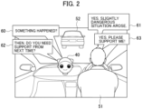
- Fig. 2 shows a scene in which a user 51 is having conversations with the robot head 40.
- the conversations are indicated by reference numerals 60 to 63.
- Reference numerals 60 and 62 indicate the speech made by the robot head 40.
- Reference numerals 61 and 63 indicate the speech made by the user 51.
- the flow of the conversations is in the order of reference numerals 60, 61, 62, and 63.
- Reference numeral 52 indicates a preceding vehicle.
- reference numerals 61 and 63 may indicate information selected by the user 51 from a plurality of options. In this case, the plurality of options are displayed on the display 42. First, conditions for outputting voice "Something happened?" indicated by reference numeral 60 will be described. The installation of the robot head 40 is not essential. A virtual robot head may be displayed on the display 42.
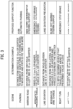
- the dangerous situation determining unit 21 determines whether the user 51 drove dangerously using data acquired from the sensor 10. An example of the determination method will be described with reference to Fig. 3 .
- the scene shown in Fig. 3 is classified into parking, a narrow road, approach to a preceding vehicle, lane deviation, merging or lane change, a right turn, and a left turn.
- the dangerous situation determining unit 21 determines that the user 51 drove dangerously.
- a distance from an obstacle is detected by a lidar.
- the number of times a steering wheel is quickly turned is detected by a steering angle sensor.
- the dangerous situation determining unit 21 determines that the user 51 drove dangerously.
- the determination is made based on the Japanese traffic rules (left-hand traffic).
- the term “left” or “right”” can be appropriately replaced according to the traffic rules of each country.
- the dangerous situation determining unit 21 determines that the user 51 drove dangerously.
- the speed of the host-vehicle is detected by the speed sensor.
- the distance from the preceding vehicle is detected by the lidar.
- the dangerous situation determining unit 21 determines that the user 51 drove dangerously.
- a distance from a road division line is detected by the camera 12.
- the dangerous situation determining unit 21 determines that the user 51 drove dangerously.
- the distance from the rear lateral side vehicles is detected by the lidar.
- the steering direction is detected by the steering angle sensor.
- TTC time to collision
- the dangerous situation determining unit 21 determines that the user 51 drove dangerously.
- the TTC with the oncoming vehicle that travels straight ahead is calculated using the speed of the oncoming vehicle that travels straight ahead and the distance to the oncoming vehicle that travels straight ahead.
- the dangerous situation determining unit 21 determines that the user 51 drove dangerously.
- a signal indicating the determination result is transmitted to the responsibility determining unit 22.
- the responsibility determining unit 22, that has received the signal determines who is responsible for dangerous driving. In the scene of Fig. 3 , the responsibility determining unit 22 determines that the user 51 is responsible for dangerous driving. In this case, a signal indicating the determination result is transmitted to the message creating unit 23.
- the message creating unit 23, which has received the signal creates a message which is indicated by reference numeral 60.
- the message creating unit 23 outputs the created message to the robot head 40. Accordingly, as shown in Fig. 2 , the message indicated by reference numeral 60 is output with voice. As shown in Fig.
- the user 51 in response to the question "Something happened?", the user 51 answers "Yes, a slightly dangerous situation arose! (reference numeral 61). This answer is a positive answer.
- the "positive answer” here means an answer in which the user 51 admits that his/her driving was dangerous.
- the voice answer made by the user 51 is output to the speech acquisition unit 24 by using the microphone 11.
- the speech acquisition unit 24 outputs the voice data of the user 51 to the speech analyzing unit 25.
- the speech analyzing unit 25 analyzes the voice data of the user 51. A well-known technique is used for the voice analysis method.
- the speech analyzing unit 25 determines whether the answer made by the user 51 is positive, based on the analysis result.
- a signal indicating the determination result is output to the message creating unit 23.
- the message indicated by reference numeral 62 is created because the answer made by the user 51 is positive. As shown in Fig.
- the user 51 in response to the question "Then, do you need support from next time?", the user 51 answers "Yes, please support me! (reference numeral 63).
- This answer is a positive answer.
- the "positive answer” here means an answer in which the user accepts a support function.
- the answer indicated by reference numeral 63 is also analyzed by the speech analyzing unit 25 in the same manner as the answer indicated by reference numeral 61. Then, the speech analyzing unit 25 determines whether the answer made by the user 51 is positive.
- a signal indicating the determination result is output to a user database 31.
- the user database 31 is stored in a storage device 30.
- the storage device 30 is constituted by hard disk drive (HDD), solid state drive (SSD), and the like.
- the position detecting unit 28 detects a position (location) of the vehicle at that time using data acquired from the GPS receiver 13. The detected position information is stored in the user database 31.
- the "support function" in the present embodiment is implemented the next time when the user 51 drives a vehicle after the messages indicated by reference numerals 60 to 63 have been exchanged.
- the camera 12 captures an image of the face of the user 51.
- the face image data captured by using the camera 12 is output to the user determination unit 27.
- the user determination unit 27 compares the face image data acquired from the camera 12 with face image data stored in advance in the user database 31 and specifies the user who has gotten on the vehicle. In the present embodiment, the user who has gotten on the vehicle is specified as the user 51.
- the reason why it is necessary to specify a user is to provide support suitable for the user. There is a case where one vehicle is shared by multiple users. In this case, it is necessary to specify the user who has gotten on the vehicle in order to provide support suitable for the user. If support is provided without specifying the user, the user may feel uncomfortable.
- the support function selecting unit 32 selects support suitable for a scene from among the plurality of support functions. As shown in Fig. 3 , when a scene is "parking", the support function selecting unit 32 selects an AVM or automatic parking from among the plurality of support functions. Note that, the support function selecting unit 32 may select the AVM and automatic parking. When a scene is a "narrow road”, the support function selecting unit 32 selects a side-down-view monitor or steering support from among the plurality of support functions. When a scene is "approach to a preceding vehicle", the support function selecting unit 32 selects an emergency stop brake or emergency avoidance steering from among the plurality of support functions.
- the support function selecting unit 32 selects lane deviation prevention from among the plurality of support functions.
- the support function selecting unit 32 selects a blind spot warning or steering support from among the plurality of support functions.
- the support function selecting unit 32 selects an emergency stop brake from among the plurality of support functions.
- the support function selecting unit 32 selects a combination of an AVM and an ultrasonic sensor from among the plurality of support functions.
- a location when the unit determined last time that the user 51 drove dangerously will be referred to as a parking space A.
- the proposal unit 33 determines that the vehicle is in the parking space A, based on position information acquired from the position detecting unit 28.
- the user 51 has accepted a support function.
- the acceptance result is recorded in the user database 31.
- the support function selecting unit 32 selects a support function to be proposed to the user 51 by referring to the user database 31.
- the support function selecting unit 32 outputs the selection result to the proposal unit 33.
- the proposal unit 33 confirms to the user 51 whether to implement the support function. The reason why the unit confirms to the user whether to implement the support function again is to enhance the trust relationship between the user 51 and the vehicle. This confirmation may be made with voice using the speaker 41 or made by displaying characters on the display 42.
- the user 51 answers to the confirmation by using the switch 14. If the user 51 presses the switch 14, it means that the user has accepted the support function. After receiving a signal indicating that the switch 14 is in an on state, the proposal unit 33 outputs an instruction for implementing the support function to the support function implementing unit 34.
- the support function implementing unit 34 which has received the instruction, controls the steering actuator 43, the accelerator pedal actuator 44, and the brake actuator 45. This performs automatic parking.
- the data at that time is recorded in the user database 31.
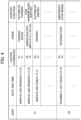
- the recorded data is the user names, date and time, locations, scenes, and implemented support functions.
- the message creating unit 23 creates the messages 60 and 62 and outputs the messages to the robot head 40
- the present invention is not limited thereto.
- These kinds of messages may be created in advance. It is sufficient if the messages created in advance are stored in the storage device 30. By referring to the storage device 30, the message creating unit 23 can output appropriate messages to the robot head 40.
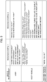
- Fig. 5 shows examples of messages created in advance. If the user 51 is responsible for dangerous driving, examples of messages selected by the message creating unit 23 include a message "Something happened?", a message "What happened?", a message "What is the matter?”, a message "Did you do something?", and a message "What did you do?”.
- the message examples 1 is intended to indirectly cause the user 51 to admit the responsibility. Meanwhile, the message example 2 of Fig. 5 is intended to specifically prompt the user 51 to answer. Examples of the message example 2 include a message "Whose fault is it?" and a message "Who is responsible for this?" as shown in Fig. 5 .
- an entity driving the vehicle is not only the user 51. Since the vehicle has automatic driving functions, driving without the intervention of the user 51 (automatic driving) is also performed. Normally, automatic driving is designed to prevent dangerous driving. However, due to unexpected factors, some sort of abnormality may occur in automatic driving.
- the "abnormality" means a state which is not normal.
- the "abnormality” is a concept that includes not only a malfunction that prevents automatic driving from exhibiting original functions thereof, but also a failure that is not as severe as a malfunction and a warning sign of a malfunction. If an abnormality occurs in automatic driving, there is a possibility that the dangerous situations shown in the determination example in Fig. 3 may arise.
- FIG. 6 shows a scene in which the user 51 is having conversations with the robot head 40.
- the conversations are indicated by reference numerals 70 to 73.
- Reference numerals 70 and 72 indicate the speech made by the robot head 40.
- Reference numerals 71 and 73 indicate the speech made by the user 51.
- the flow of the conversations is in the order of reference numerals 70, 71, 72, and 73.
- the conditions for outputting a message "Were you scared?" indicated by reference numeral 70 will be described below.
- a signal indicating the determination result is transmitted to the responsibility determining unit 22.
- the responsibility determining unit 22, which has received the signal determines who is responsible for dangerous driving.
- the responsibility determining unit 22 determines that automatic driving (vehicle) is responsible for dangerous driving.
- a signal indicating the determination result is transmitted to the message creating unit 23.
- the message creating unit 23, which has received the signal creates the message indicated by reference numeral 70.
- the message creating unit 23 outputs the created message to the robot head 40.
- the message indicated by reference numeral 70 is output with voice as shown in Fig. 6 .
- the user 51 in response to the question "Were you scared?", the user 51 answers "Yes, a distance from another vehicle is too short! (reference numeral 71).
- This answer is a positive answer.
- the "positive answer” means an answer in which the user 51 admits that automatic driving has been dangerous driving.
- the answer made by the user 51 is analyzed based on the same method described above. Based on the analysis result, the message creating unit 23 creates a message (Then, do you want to increase the distance from next time?) indicated by reference numeral 72.
- the message indicated by reference numeral 72 is created, because the answer made by the user 51 has been positive. As shown in Fig.
- the user 51 in response to the question "Then, do you want to increase the distance from next time?", the user 51 answers "Yes, please increase the distance! (reference numeral 73).
- This answer is a positive answer.
- the "positive answer” is an answer for changing a parameter of a support function (automatic driving function).
- the answer indicated by reference numeral 73 is analyzed by the speech analyzing unit 25. Then, it is determined whether the answer made by the user 51 is positive. A signal indicating the determination result is output to the parameter changing unit 26.
- the parameter changing unit 26 changes a distance from another vehicle such that the distance becomes longer compared with that in previous automatic driving.
- the changed parameter is output to the support function implementing unit 34.
- the support function implementing unit 34 controls the distance from another vehicle based on the changed parameter. As a result, it is possible to perform driving support suitable for a user's feeling.
- the messages indicated by reference numerals 70 and 72 may also be created in advance in the same manner as the messages indicated by reference numerals 60 and 62.
- examples of messages selected by the message creating unit 23 include a message "Did you feel unsafe?", a message “Was the driving dangerous?”, and a message “Were you scared?” as shown in FIG. 5 .
- Examples of other messages include a message “Was a brake applied too late?”, a message “Was a distance from another vehicle too short?”, a message “Was a preceding vehicle too close?", a message “Was an accelerator pressed too much?", a message “Too fast?", a message “Too slow?”, a message “Was a steering wheel turned too late/too fast?”, a message “Was the vehicle positioned too close to the right/left?”, a message “Did vehicle sway?”, and a message "Was vehicle in a jerky motion?”.
- a cause of occurrence of a dangerous situation is not limited to driving by the user 51 or automatic driving.
- a cause may be driving by a user in another vehicle, automatic driving of another vehicle, a pedestrian, or the like.
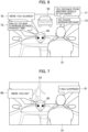
- Fig. 7 shows a scene in which a dangerous situation arose due to a pedestrian 53 dashing out.
- Reference numeral 80 indicates a speech made by the robot head 40.
- Reference numeral 81 indicates a speech made by the user 51.
- the flow of conversations is in the order of reference numerals 80 and 81.
- the message creating unit 23 creates a message (Were you OK?) indicated by reference numeral 80 and outputs the message to the robot head 40.
- step S101 When an ignition is in an on state (YES in step S101), processing proceeds to step S103.
- the information that "the ignition is in an on state" means that a power supply of the vehicle is turned on.
- steps S103 and S105 the dangerous situation determining unit 21 determines whether a dangerous situation has occurred using data acquired from the sensor 10. If a dangerous situation has occurred (YES in step S105), the processing proceeds to step S107.
- step S107 the responsibility determining unit 22 estimates a cause of occurrence of the dangerous situation, based on the data acquired from the sensor 10. For example, if the dangerous situations shown in Fig. 3 occur due to driving by the user 51, it is estimated that the user 51 is responsible for dangerous driving (YES in step S113). If the dangerous situations shown in Fig.
- step S113 automatic driving functions of the host-vehicle
- NO in step S113 automatic driving functions of another vehicle
- a dangerous situation occurs due to driving by a user in another vehicle, automatic driving functions of another vehicle, or a pedestrian and the like
- a user of another vehicle, another vehicle, or a pedestrian and the like is responsible for dangerous driving (NO in step S109).
- the "pedestrian and the like” includes a pedestrian, a bicycle, and a motorcycle.
- step S111 the message indicated by reference numeral 80 is output (see Fig. 7 ).
- step S115 the message indicated by reference numeral 60 is output (see Fig. 2 ).
- the processing proceeds to step S117, and the speech acquisition unit 24 acquires an answer made by the user 51 using the microphone 11. If an answer made by the user 51 is determined to be positive (YES in step S119), the message indicated by reference numeral 62 for proposing a support function is output (see Fig. 2 ). If an answer by made the user 51 is determined to be negative (NO in step S119), a message indicating that the user 51 is responsible for dangerous driving is output.
- step S127 the message indicated by reference numeral 70 is output (see Fig. 6 ).
- the processing proceeds to step S129, and the speech acquisition unit 24 acquires an answer made by the user 51 using the microphone 11. If an answer made by the user 51 is determined to be positive (YES in step S131), the parameter changing unit 26 reflects a request made by the user 51 in control contents when automatic driving is performed next time (step S133). Specifically, the parameter changing unit 26 changes a parameter related to an automatic driving function. As an example of parameter change, a distance with another vehicle is changed to a longer distance. If an answer made by the user 51 is determined to be negative (NO in step S13 1), a parameter is not changed. The processing in steps S103 to S135 is repeated until the ignition is in an off state.
- step S203 the proposal unit 33 acquires position information from the position detecting unit 28.
- step S205 the proposal unit 33 determines, based on the position information, whether a current position of the vehicle is a position where a support function was proposed last time. The "position where a support function was proposed last time" will be referred to as a "position A”.
- the support function selecting unit 32 refers to the user database 31 and proposes a support function to the user 51 (step S207).
- step S209 If the user 51 accepts the support function (YES in step S209), the support function implementing unit 34 implements the support function (step S211). If the user 51 does not accept the support function (NO in step S209), the support function implementing unit 34 does not implement the support function (step S213). Data when the vehicle passes the position A (YES in step S215) is recorded in the user database 31 (step S217). The processing in steps S203 to S217 is repeated until the ignition is in an off state.
- the driving support device 1 includes the sensor 10 for acquiring data of a space inside the vehicle and data of a space outside the vehicle, and the controller 20.
- the controller 20 determines whether the vehicle is in an abnormal state, based on the data acquired by the sensor 10. If the controller 20 determines that the vehicle is in an abnormal state, the controller 20 outputs a message indicating that the vehicle is in an abnormal state to the user 51 who is on the vehicle.
- the controller 20 acquires an answer made by the user 51 in response to the message using an input device.
- An example of an input device is the microphone 11.
- the information that "the vehicle is in an abnormal state” means a situation where there is a possibility of collision or accident of the vehicle. It is sufficient if the "possibility of collision or accident of the vehicle" is determined based only on the data acquired by the sensor 10. It does not matter whether an entity performing driving is the user 51 or an automatic driving function. However, an entity performing driving may be considered as described later.
- An answer made by the user 51 relates to a feeling indicating anxiety or danger about the condition of the vehicle.
- the controller 20 determines that an answer made by the user 51 in response to the message indicates the feeling of anxiety or danger, the controller 20 proposes the user to use a support function for supporting the user 51.
- An example of an answer indicating the feeling of anxiety or danger is the message indicated by reference numeral 61 shown in Fig. 2 .
- the controller 20 estimates a cause of occurrence of the abnormal state, based on the data acquired by the sensor 10. If the controller 20 estimates that a cause arises from driving by the user 51, the controller 20 outputs a message for confirming responsibility to the user 51. An example of the message for confirming responsibility is a message "Who is responsible for this?" shown in Fig. 5 . If the controller 20 determines that an answer made by the user 51 in response to the message is for admitting the responsibility, the controller 20 proposes the user to use a support function for supporting the user 51. As a result, it is possible to provide driving support that is suitable for a feeling of the user 51. In addition, by causing the user 51 himself/herself to admit the responsibility, it is possible to make the relationship between the user 51 and the vehicle friendly.
- the messages include a message for confirming responsibility to the user 51, a message concerning the condition of the vehicle, a message for confirming a feeling of the user 51, or a message for confirming safety of the user 51.
- An example of the "message for confirming responsibility to the user 51" is a message "Who is responsible for this?" shown in Fig. 5 .
- An example of the "message concerning the condition of the vehicle” is a message “Did you apply a brake too late?” shown in Fig. 5 .
- An example of the "message for confirming a feeling of the user 51” is a message "Were you scared?" shown in Fig. 5 .
- An example of the "message for confirming safety of the user 51” is a message "Did you feel unsafe?" shown in Fig. 5 .
- An example of the message for confirming responsibility to the user 51 is a message for confirming to the user 51 whether something has happened in the vehicle or in a periphery of the vehicle (see Fig. 5 ).
- the controller 20 determines that an answer made by the user 51 in response to the message for confirming responsibility indicates that the user does not admit the responsibility, the controller 20 outputs a message indicating that the user 51 is responsible for the situation. This can provide, to the user 51, an opportunity to change his/her attitude.
- the controller 20 estimates a cause of occurrence of the abnormal state, based on the data acquired by the sensor 10. If the controller 20 estimates that a cause arises from the automatic driving function, the controller 20 outputs a message for confirming whether the user 51 had a feeling of anxiety.
- An example of the "message for confirming whether the user 51 had a feeling of anxiety" is a message "Were you scared?" shown in Fig. 5 . Accordingly, it is possible to confirm whether the user 51 has a feeling of anxiety to automatic driving.
- the controller 20 determines that an answer made by the user 51 in response to the message for confirming anxiety indicates that the user had a feeling of anxiety
- the controller 20 changes setting of a parameter of the automatic driving function. Specifically, the controller 20 changes the parameter of the automatic driving function to the safe side.
- An example of the parameter change is to increase a distance from another vehicle. As a result, it becomes possible to provide driving support suitable for a feeling of the user 51. In addition, the reliability to automatic driving is enhanced.
- the processing circuit includes a programmed processing device such as a processing device including an electrical circuit.
- the processing circuit also includes devices such as application specific integrated circuits (ASICs) and circuit components that are arranged to perform the described functions.
- ASICs application specific integrated circuits
Landscapes
- Engineering & Computer Science (AREA)
- Automation & Control Theory (AREA)
- Human Computer Interaction (AREA)
- Transportation (AREA)
- Mechanical Engineering (AREA)
- Physics & Mathematics (AREA)
- General Physics & Mathematics (AREA)
- Traffic Control Systems (AREA)
- Control Of Driving Devices And Active Controlling Of Vehicle (AREA)
Abstract
Description
- The present invention relates to a driving support device and a driving support method.
- There is a prior known invention for detecting dangerous driving performed by a user and presenting driving characteristics to the user (Patent Literature 1).
- Patent Literature 1:
Japanese Patent No. 6480143 - However, in the invention disclosed in
Patent Literature 1, a system determines whether driving is dangerous driving. A user himself/herself determines whether to admit the determination result. Therefore, driving support based on the determination result may not be effective. - The present invention has been made in view of the above problem, and an object of the present invention is to provide a driving support device and a driving support method capable of providing driving support suitable for a user's feeling.
- A driving support device according to an aspect of the present invention determines whether a vehicle is in an abnormal state based on data acquired by a sensor, upon determining that the vehicle is in the abnormal state, outputs a message indicating that the vehicle is in the abnormal state to a user on the vehicle, and acquires an answer from the user to the message via an input device.
- According to the present invention, it is possible to provide driving support suitable for a user's feeling.
-
- [
Fig. 1] Fig. 1 is a diagram showing a configuration of adriving support device 1 according to an embodiment of the present invention. - [
Fig. 2] Fig. 2 shows conversations made between auser 51 and arobot head 40. - [
Fig. 3] Fig. 3 is an example of a method for determining dangerous driving. - [
Fig. 4] Fig. 4 is an example of data stored when a support function is implemented. - [
Fig. 5] Fig. 5 is an example of messages output from therobot head 40. - [
Fig. 6] Fig. 6 shows conversations made between theuser 51 and therobot head 40. - [
Fig. 7] Fig. 7 shows conversations made between theuser 51 and therobot head 40. - [
Fig. 8] Fig. 8 is a flowchart for explaining an operation example of thedriving support device 1. - [
Fig. 9] Fig. 9 is a flowchart for explaining an operation example of thedriving support device 1. - [
Fig. 10] Fig. 10 is a flowchart for explaining an operation example of thedriving support device 1. - An embodiment of the present invention will be described below with reference to the drawings. In the description of the drawings, the same parts are denoted by the same reference numerals and the explanation thereof will be omitted.
- An example of a configuration of a
driving support device 1 will be described with reference toFig. 1 . As shown inFig. 1 , thedriving support device 1 includes asensor 10, amicrophone 11, acamera 12, aGPS receiver 13, aswitch 14, acontroller 20, arobot head 40, aspeaker 41, adisplay 42, asteering actuator 43, anaccelerator pedal actuator 44, and abrake actuator 45. - The
driving support device 1 is mounted on a vehicle having automatic driving functions. Thedriving support device 1 may be mounted on a vehicle that can switch between automatic driving and manual driving. As an example, the automatic driving functions perform automatic control such as steering control, braking force control, and driving force control and support driving of a user. In the present embodiment, a "user" means a user who is sitting in a driver's seat of a vehicle. - The
sensor 10 is used to acquire various pieces of data and information. Examples of thesensor 10 include a sensor for acquiring data of a vehicle and a sensor for acquiring vehicle external information. An example of the data of a vehicle is the speed, acceleration, steering angle, brake hydraulic pressure, and accelerator opening. Examples of sensors that acquire these pieces of data include speed sensors, acceleration sensors, steering angle sensors, gyro sensors, brake hydraulic pressure sensors, and accelerator opening sensors. - Examples of the vehicle external information include an object (a pedestrian, bicycle, motorcycle, another vehicle, and the like) present in a periphery of a vehicle (host-vehicle), a traffic light, road division line, sign, pedestrian crosswalk, intersection, and the like. Examples of the sensor for acquiring these pieces of information include a laser range finder, radar, lidar, the
camera 12, a sonar, and the like. In the present embodiment, thesensor 10 is distinguished form thecamera 12 for convenience of explanation, but thecamera 12 is a type of thesensor 10. The data and information acquired by thesensor 10 are output to thecontroller 20. - The
microphone 11 acquires voice data of the user. The voice data acquired by themicrophone 11 is output to thecontroller 20. - The
camera 12 has an imaging element such as a charge-coupled device (CCD) or a complementary metal oxide semiconductor (CMOS). The installation position of thecamera 12 is not particularly limited, but as an example, thecamera 12 is installed in the front, sides, or rear of a vehicle. Thecamera 12 captures an image of a space around the vehicle. The image data captured by using thecamera 12 is output to thecontroller 20. Further, in the present embodiment, thecamera 12 is also installed inside a vehicle. For example, thecamera 12 is installed near a driver's seat to capture an image the user's face. The face image data captured by using thecamera 12 is output to thecontroller 20. - The
GPS receiver 13 detects position information of a vehicle on the ground by receiving radio waves from an artificial satellite. The position information of the vehicle detected by theGPS receiver 13 includes latitude information and longitude information. TheGPS receiver 13 outputs the detected position information of the vehicle to thecontroller 20. An entity performing the method for detecting the position information of the vehicle is not limited to theGPS receiver 13. For example, the position of the vehicle may be estimated using a method called an odometry. The odometry is a method for estimating a position of a vehicle by obtaining the amount of movement and a movement direction of the vehicle in accordance with a rotation angle and a rotation angular speed of the vehicle. A GNSS receiver may be used instead of theGPS receiver 13. - The
switch 14 is used when the user uses support functions. When the user presses theswitch 14, the support functions are activated. The "support functions" in the present embodiment include an around-view monitor (hereinafter referred to as an AVM), automatic parking, a side-down-view monitor, steering support, emergency stop brake, emergency avoidance steering, lane deviation prevention, blind spot warning, a combination of an AVM and an ultrasonic sensor, and the like. Since the support functions are well known, a detailed description thereof will be omitted. Theswitch 14 may be a physical switch or a virtual switch. The virtual switch is, for example, a switch displayed on thedisplay 42. Some of the support functions described above are also the automatic driving functions. That is, the support functions of the present embodiment include the automatic driving functions. The automatic driving functions include adaptive cruise control (ACC), constant speed control, and the like. - The
controller 20 is a general-purpose microcomputer that includes a central processing unit (CPU), a memory, and an input/output unit. A computer program for causing the microcomputer to function as the drivingsupport device 1 is installed in the microcomputer. By executing the computer program, the microcomputer functions as a plurality of information processing circuits in the drivingsupport device 1. Here, an example of realizing the plurality of information processing circuits in the drivingsupport device 1 by software is shown. However, it is also possible to configure each information processing circuit by preparing dedicated hardware for performing each information processing described below. Further, the plurality of information processing circuits may be configured by individual pieces of hardware. As an example of the plurality of information processing circuits, thecontroller 20 includes a dangeroussituation determining unit 21, aresponsibility determining unit 22, amessage creating unit 23, aspeech acquisition unit 24, aspeech analyzing unit 25, aparameter changing unit 26, auser determination unit 27, aposition detecting unit 28, a supportfunction selecting unit 32, aproposal unit 33, and a supportfunction implementing unit 34. - The
robot head 40 is a figurine imitating a head of a robot. Therobot head 40 is installed to enhance the affinity between a user and a vehicle. Therobot head 40 has a speaker function and an information processing function. - Next, with reference to
Figs. 2 to 7 , the details of the dangeroussituation determining unit 21, theresponsibility determining unit 22, themessage creating unit 23, thespeech acquisition unit 24, thespeech analyzing unit 25, theparameter changing unit 26, theuser determination unit 27, theposition detecting unit 28, the supportfunction selecting unit 32, theproposal unit 33, and the supportfunction implementing unit 34 will be described. -
Fig. 2 shows a scene in which auser 51 is having conversations with therobot head 40. The conversations are indicated byreference numerals 60 to 63.Reference numerals robot head 40.Reference numerals user 51. The flow of the conversations is in the order ofreference numerals Reference numeral 52 indicates a preceding vehicle. Although a description will be given by assuming that all ofreference numerals 60 to 63 indicate voice, the present invention is not limited thereto. For example, contents indicated byreference numerals display 42 as characters. Further,reference numerals user 51 from a plurality of options. In this case, the plurality of options are displayed on thedisplay 42. First, conditions for outputting voice "Something happened?" indicated byreference numeral 60 will be described. The installation of therobot head 40 is not essential. A virtual robot head may be displayed on thedisplay 42. - The dangerous
situation determining unit 21 determines whether theuser 51 drove dangerously using data acquired from thesensor 10. An example of the determination method will be described with reference toFig. 3 . The scene shown inFig. 3 is classified into parking, a narrow road, approach to a preceding vehicle, lane deviation, merging or lane change, a right turn, and a left turn. In the scene of "parking", if a distance from an obstacle is 15 cm or shorter, or the number of times a steering wheel is quickly turned to move the vehicle back and forth is five times or more, the dangeroussituation determining unit 21 determines that theuser 51 drove dangerously. A distance from an obstacle is detected by a lidar. The number of times a steering wheel is quickly turned is detected by a steering angle sensor. In the scene of "narrow road", if a distance from an obstacle on the left side is 15 cm or shorter, the dangeroussituation determining unit 21 determines that theuser 51 drove dangerously. Here, the determination is made based on the Japanese traffic rules (left-hand traffic). The term "left" or "right"" can be appropriately replaced according to the traffic rules of each country. - In the scene of "approach to a preceding vehicle", if the speed of the host-vehicle is 15 km/h or higher, and a distance from a preceding vehicle is 5 m or shorter, the dangerous
situation determining unit 21 determines that theuser 51 drove dangerously. The speed of the host-vehicle is detected by the speed sensor. The distance from the preceding vehicle is detected by the lidar. In the scene of "lane deviation", if a distance from either one of left and right road division lines is 5 cm or shorter, the dangeroussituation determining unit 21 determines that theuser 51 drove dangerously. A distance from a road division line is detected by thecamera 12. In the scene of "merging or lane change", if the distance from rear lateral side vehicles is 5 m or shorter, and the host-vehicle is steered in the directions, the dangeroussituation determining unit 21 determines that theuser 51 drove dangerously. The distance from the rear lateral side vehicles is detected by the lidar. The steering direction is detected by the steering angle sensor. In the scene of "right turn", if time to collision (TTC) with an oncoming vehicle that travels straight ahead is equal to or less than a prescribed value, the dangeroussituation determining unit 21 determines that theuser 51 drove dangerously. The TTC with the oncoming vehicle that travels straight ahead is calculated using the speed of the oncoming vehicle that travels straight ahead and the distance to the oncoming vehicle that travels straight ahead. In the scene of "left turn", if a distance from an obstacle on the left side is 15 cm or shorter, the dangeroussituation determining unit 21 determines that theuser 51 drove dangerously. - If the dangerous
situation determining unit 21 determines that theuser 51 drove dangerously, a signal indicating the determination result is transmitted to theresponsibility determining unit 22. Theresponsibility determining unit 22, that has received the signal, determines who is responsible for dangerous driving. In the scene ofFig. 3 , theresponsibility determining unit 22 determines that theuser 51 is responsible for dangerous driving. In this case, a signal indicating the determination result is transmitted to themessage creating unit 23. Themessage creating unit 23, which has received the signal, creates a message which is indicated byreference numeral 60. Themessage creating unit 23 outputs the created message to therobot head 40. Accordingly, as shown inFig. 2 , the message indicated byreference numeral 60 is output with voice. As shown inFig. 2 , in response to the question "Something happened?", theuser 51 answers "Yes, a slightly dangerous situation arose!" (reference numeral 61). This answer is a positive answer. The "positive answer" here means an answer in which theuser 51 admits that his/her driving was dangerous. - The voice answer made by the
user 51 is output to thespeech acquisition unit 24 by using themicrophone 11. Thespeech acquisition unit 24 outputs the voice data of theuser 51 to thespeech analyzing unit 25. Thespeech analyzing unit 25 analyzes the voice data of theuser 51. A well-known technique is used for the voice analysis method. Thespeech analyzing unit 25 determines whether the answer made by theuser 51 is positive, based on the analysis result. A signal indicating the determination result is output to themessage creating unit 23. Themessage creating unit 23, which has received the signal, creates a message (Then, do you need support from next time?) indicated byreference numeral 62. The message indicated byreference numeral 62 is created because the answer made by theuser 51 is positive. As shown inFig. 2 , in response to the question "Then, do you need support from next time?", theuser 51 answers "Yes, please support me!" (reference numeral 63). This answer is a positive answer. The "positive answer" here means an answer in which the user accepts a support function. The answer indicated byreference numeral 63 is also analyzed by thespeech analyzing unit 25 in the same manner as the answer indicated byreference numeral 61. Then, thespeech analyzing unit 25 determines whether the answer made by theuser 51 is positive. A signal indicating the determination result is output to auser database 31. Theuser database 31 is stored in astorage device 30. Thestorage device 30 is constituted by hard disk drive (HDD), solid state drive (SSD), and the like. - If it is determined that the
user 51 drove dangerously, theposition detecting unit 28 detects a position (location) of the vehicle at that time using data acquired from theGPS receiver 13. The detected position information is stored in theuser database 31. - The "support function" in the present embodiment is implemented the next time when the
user 51 drives a vehicle after the messages indicated byreference numerals 60 to 63 have been exchanged. When theuser 51 gets on a vehicle, thecamera 12 captures an image of the face of theuser 51. The face image data captured by using thecamera 12 is output to theuser determination unit 27. Theuser determination unit 27 compares the face image data acquired from thecamera 12 with face image data stored in advance in theuser database 31 and specifies the user who has gotten on the vehicle. In the present embodiment, the user who has gotten on the vehicle is specified as theuser 51. The reason why it is necessary to specify a user is to provide support suitable for the user. There is a case where one vehicle is shared by multiple users. In this case, it is necessary to specify the user who has gotten on the vehicle in order to provide support suitable for the user. If support is provided without specifying the user, the user may feel uncomfortable. - The support
function selecting unit 32 selects support suitable for a scene from among the plurality of support functions. As shown inFig. 3 , when a scene is "parking", the supportfunction selecting unit 32 selects an AVM or automatic parking from among the plurality of support functions. Note that, the supportfunction selecting unit 32 may select the AVM and automatic parking. When a scene is a "narrow road", the supportfunction selecting unit 32 selects a side-down-view monitor or steering support from among the plurality of support functions. When a scene is "approach to a preceding vehicle", the supportfunction selecting unit 32 selects an emergency stop brake or emergency avoidance steering from among the plurality of support functions. When a scene is a "lane deviation", the supportfunction selecting unit 32 selects lane deviation prevention from among the plurality of support functions. When a scene is a "merging or lane change", the supportfunction selecting unit 32 selects a blind spot warning or steering support from among the plurality of support functions. When a scene is a "right turn", the supportfunction selecting unit 32 selects an emergency stop brake from among the plurality of support functions. When a scene is a "left turn", the supportfunction selecting unit 32 selects a combination of an AVM and an ultrasonic sensor from among the plurality of support functions. - Here, support when a scene is "parking" will be described. A location when the unit determined last time that the
user 51 drove dangerously will be referred to as a parking space A. Is is assumed that theuser 51 goes to the parking space A again. Theproposal unit 33 determines that the vehicle is in the parking space A, based on position information acquired from theposition detecting unit 28. In the exchange of the messages (exchange of the messages indicated byreference numerals 60 to 63) made last time, theuser 51 has accepted a support function. The acceptance result is recorded in theuser database 31. The supportfunction selecting unit 32 selects a support function to be proposed to theuser 51 by referring to theuser database 31. Here, it is assumed that automatic parking is selected. The supportfunction selecting unit 32 outputs the selection result to theproposal unit 33. Theproposal unit 33 confirms to theuser 51 whether to implement the support function. The reason why the unit confirms to the user whether to implement the support function again is to enhance the trust relationship between theuser 51 and the vehicle. This confirmation may be made with voice using thespeaker 41 or made by displaying characters on thedisplay 42. Theuser 51 answers to the confirmation by using theswitch 14. If theuser 51 presses theswitch 14, it means that the user has accepted the support function. After receiving a signal indicating that theswitch 14 is in an on state, theproposal unit 33 outputs an instruction for implementing the support function to the supportfunction implementing unit 34. The supportfunction implementing unit 34, which has received the instruction, controls thesteering actuator 43, theaccelerator pedal actuator 44, and thebrake actuator 45. This performs automatic parking. - When the support function is implemented, the data at that time is recorded in the
user database 31. As shown inFig. 4 , the recorded data is the user names, date and time, locations, scenes, and implemented support functions. - Although a description has be given by assuming that the
message creating unit 23 creates themessages robot head 40, the present invention is not limited thereto. These kinds of messages may be created in advance. It is sufficient if the messages created in advance are stored in thestorage device 30. By referring to thestorage device 30, themessage creating unit 23 can output appropriate messages to therobot head 40.Fig. 5 shows examples of messages created in advance. If theuser 51 is responsible for dangerous driving, examples of messages selected by themessage creating unit 23 include a message "Something happened?", a message "What happened?", a message "What is the matter?", a message "Did you do something?", and a message "What did you do?". The message examples 1 is intended to indirectly cause theuser 51 to admit the responsibility. Meanwhile, the message example 2 ofFig. 5 is intended to specifically prompt theuser 51 to answer. Examples of the message example 2 include a message "Whose fault is it?" and a message "Who is responsible for this?" as shown inFig. 5 . - In the above example, it is determined that the
user 51 drove dangerously. Here, an entity driving the vehicle is not only theuser 51. Since the vehicle has automatic driving functions, driving without the intervention of the user 51 (automatic driving) is also performed. Normally, automatic driving is designed to prevent dangerous driving. However, due to unexpected factors, some sort of abnormality may occur in automatic driving. Here, the "abnormality" means a state which is not normal. The "abnormality" is a concept that includes not only a malfunction that prevents automatic driving from exhibiting original functions thereof, but also a failure that is not as severe as a malfunction and a warning sign of a malfunction. If an abnormality occurs in automatic driving, there is a possibility that the dangerous situations shown in the determination example inFig. 3 may arise. A conversation example when an abnormality occurs in automatic driving will be described with reference toFig. 6. Fig. 6 shows a scene in which theuser 51 is having conversations with therobot head 40. The conversations are indicated byreference numerals 70 to 73.Reference numerals robot head 40.Reference numerals user 51. The flow of the conversations is in the order ofreference numerals reference numeral 70 will be described below. - If the dangerous
situation determining unit 21 determines that an abnormality has occurred in automatic driving, a signal indicating the determination result is transmitted to theresponsibility determining unit 22. Theresponsibility determining unit 22, which has received the signal, determines who is responsible for dangerous driving. Here, theresponsibility determining unit 22 determines that automatic driving (vehicle) is responsible for dangerous driving. A signal indicating the determination result is transmitted to themessage creating unit 23. Themessage creating unit 23, which has received the signal, creates the message indicated byreference numeral 70. Themessage creating unit 23 outputs the created message to therobot head 40. As a result, the message indicated byreference numeral 70 is output with voice as shown inFig. 6 . As shown inFig. 6 , in response to the question "Were you scared?", theuser 51 answers "Yes, a distance from another vehicle is too short!" (reference numeral 71). This answer is a positive answer. Here, the "positive answer" means an answer in which theuser 51 admits that automatic driving has been dangerous driving. The answer made by theuser 51 is analyzed based on the same method described above. Based on the analysis result, themessage creating unit 23 creates a message (Then, do you want to increase the distance from next time?) indicated byreference numeral 72. The message indicated byreference numeral 72 is created, because the answer made by theuser 51 has been positive. As shown inFig. 6 , in response to the question "Then, do you want to increase the distance from next time?", theuser 51 answers "Yes, please increase the distance!" (reference numeral 73). This answer is a positive answer. Here, the "positive answer" is an answer for changing a parameter of a support function (automatic driving function). The answer indicated byreference numeral 73 is analyzed by thespeech analyzing unit 25. Then, it is determined whether the answer made by theuser 51 is positive. A signal indicating the determination result is output to theparameter changing unit 26. Next time, when automatic driving is performed, theparameter changing unit 26 changes a distance from another vehicle such that the distance becomes longer compared with that in previous automatic driving. The changed parameter is output to the supportfunction implementing unit 34. The supportfunction implementing unit 34 controls the distance from another vehicle based on the changed parameter. As a result, it is possible to perform driving support suitable for a user's feeling. - The messages indicated by
reference numerals reference numerals message creating unit 23 include a message "Did you feel unsafe?", a message "Was the driving dangerous?", and a message "Were you scared?" as shown inFIG. 5 . Examples of other messages include a message "Was a brake applied too late?", a message "Was a distance from another vehicle too short?", a message "Was a preceding vehicle too close?", a message "Was an accelerator pressed too much?", a message "Too fast?", a message "Too slow?", a message "Was a steering wheel turned too late/too fast?", a message "Was the vehicle positioned too close to the right/left?", a message "Did vehicle sway?", and a message "Was vehicle in a jerky motion?". - A cause of occurrence of a dangerous situation is not limited to driving by the
user 51 or automatic driving. For example, a cause may be driving by a user in another vehicle, automatic driving of another vehicle, a pedestrian, or the like.Fig. 7 shows a scene in which a dangerous situation arose due to apedestrian 53 dashing out.Reference numeral 80 indicates a speech made by therobot head 40.Reference numeral 81 indicates a speech made by theuser 51. The flow of conversations is in the order ofreference numerals pedestrian 53, themessage creating unit 23 creates a message (Were you OK?) indicated byreference numeral 80 and outputs the message to therobot head 40. - Next, an operation example of the driving
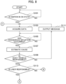
support device 1 will be described with reference to the flowchart ofFigs. 8 and9 . - When an ignition is in an on state (YES in step S101), processing proceeds to step S103. The information that "the ignition is in an on state" means that a power supply of the vehicle is turned on. In steps S103 and S105, the dangerous
situation determining unit 21 determines whether a dangerous situation has occurred using data acquired from thesensor 10. If a dangerous situation has occurred (YES in step S105), the processing proceeds to step S107. In step S107, theresponsibility determining unit 22 estimates a cause of occurrence of the dangerous situation, based on the data acquired from thesensor 10. For example, if the dangerous situations shown inFig. 3 occur due to driving by theuser 51, it is estimated that theuser 51 is responsible for dangerous driving (YES in step S113). If the dangerous situations shown inFig. 3 occur due to automatic driving functions of the host-vehicle, it is estimated that automatic driving (vehicle) is responsible for dangerous driving (NO in step S113). If a dangerous situation occurs due to driving by a user in another vehicle, automatic driving functions of another vehicle, or a pedestrian and the like, it is estimated that a user of another vehicle, another vehicle, or a pedestrian and the like is responsible for dangerous driving (NO in step S109). The "pedestrian and the like" includes a pedestrian, a bicycle, and a motorcycle. - In step S111, the message indicated by
reference numeral 80 is output (seeFig. 7 ). In step S115, the message indicated byreference numeral 60 is output (seeFig. 2 ). The processing proceeds to step S117, and thespeech acquisition unit 24 acquires an answer made by theuser 51 using themicrophone 11. If an answer made by theuser 51 is determined to be positive (YES in step S119), the message indicated byreference numeral 62 for proposing a support function is output (seeFig. 2 ). If an answer by made theuser 51 is determined to be negative (NO in step S119), a message indicating that theuser 51 is responsible for dangerous driving is output. - In step S127, the message indicated by
reference numeral 70 is output (seeFig. 6 ). The processing proceeds to step S129, and thespeech acquisition unit 24 acquires an answer made by theuser 51 using themicrophone 11. If an answer made by theuser 51 is determined to be positive (YES in step S131), theparameter changing unit 26 reflects a request made by theuser 51 in control contents when automatic driving is performed next time (step S133). Specifically, theparameter changing unit 26 changes a parameter related to an automatic driving function. As an example of parameter change, a distance with another vehicle is changed to a longer distance. If an answer made by theuser 51 is determined to be negative (NO in step S13 1), a parameter is not changed. The processing in steps S103 to S135 is repeated until the ignition is in an off state. - Next, an operation example of the driving
support device 1 will be described with reference to the flowchart ofFig. 10 . - When the ignition is in an on state (YES in step S201), the processing proceeds to step S203. In step S203, the
proposal unit 33 acquires position information from theposition detecting unit 28. In step S205, theproposal unit 33 determines, based on the position information, whether a current position of the vehicle is a position where a support function was proposed last time. The "position where a support function was proposed last time" will be referred to as a "position A". When the current position of the vehicle is the position A (YES in step S205), the supportfunction selecting unit 32 refers to theuser database 31 and proposes a support function to the user 51 (step S207). If theuser 51 accepts the support function (YES in step S209), the supportfunction implementing unit 34 implements the support function (step S211). If theuser 51 does not accept the support function (NO in step S209), the supportfunction implementing unit 34 does not implement the support function (step S213). Data when the vehicle passes the position A (YES in step S215) is recorded in the user database 31 (step S217). The processing in steps S203 to S217 is repeated until the ignition is in an off state. - As described above, the following actions and effects can be acquired in accordance with the driving
support device 1 according to the present embodiment. - The driving
support device 1 includes thesensor 10 for acquiring data of a space inside the vehicle and data of a space outside the vehicle, and thecontroller 20. Thecontroller 20 determines whether the vehicle is in an abnormal state, based on the data acquired by thesensor 10. If thecontroller 20 determines that the vehicle is in an abnormal state, thecontroller 20 outputs a message indicating that the vehicle is in an abnormal state to theuser 51 who is on the vehicle. Thecontroller 20 acquires an answer made by theuser 51 in response to the message using an input device. An example of an input device is themicrophone 11. By providing support according to an answer made by theuser 51, it is possible to provide driving support suitable for a feeling of theuser 51. - The information that "the vehicle is in an abnormal state" means a situation where there is a possibility of collision or accident of the vehicle. It is sufficient if the "possibility of collision or accident of the vehicle" is determined based only on the data acquired by the
sensor 10. It does not matter whether an entity performing driving is theuser 51 or an automatic driving function. However, an entity performing driving may be considered as described later. - An answer made by the
user 51 relates to a feeling indicating anxiety or danger about the condition of the vehicle. - If the
controller 20 determines that an answer made by theuser 51 in response to the message indicates the feeling of anxiety or danger, thecontroller 20 proposes the user to use a support function for supporting theuser 51. An example of an answer indicating the feeling of anxiety or danger is the message indicated byreference numeral 61 shown inFig. 2 . As a result, it is possible to provide driving support suitable for a feeling of theuser 51. - The
controller 20 estimates a cause of occurrence of the abnormal state, based on the data acquired by thesensor 10. If thecontroller 20 estimates that a cause arises from driving by theuser 51, thecontroller 20 outputs a message for confirming responsibility to theuser 51. An example of the message for confirming responsibility is a message "Who is responsible for this?" shown inFig. 5 . If thecontroller 20 determines that an answer made by theuser 51 in response to the message is for admitting the responsibility, thecontroller 20 proposes the user to use a support function for supporting theuser 51. As a result, it is possible to provide driving support that is suitable for a feeling of theuser 51. In addition, by causing theuser 51 himself/herself to admit the responsibility, it is possible to make the relationship between theuser 51 and the vehicle friendly. - The messages include a message for confirming responsibility to the
user 51, a message concerning the condition of the vehicle, a message for confirming a feeling of theuser 51, or a message for confirming safety of theuser 51. An example of the "message for confirming responsibility to theuser 51" is a message "Who is responsible for this?" shown inFig. 5 . An example of the "message concerning the condition of the vehicle" is a message "Did you apply a brake too late?" shown inFig. 5 . An example of the "message for confirming a feeling of theuser 51" is a message "Were you scared?" shown inFig. 5 . An example of the "message for confirming safety of theuser 51" is a message "Did you feel unsafe?" shown inFig. 5 . - An example of the message for confirming responsibility to the
user 51 is a message for confirming to theuser 51 whether something has happened in the vehicle or in a periphery of the vehicle (seeFig. 5 ). - If the
controller 20 determines that an answer made by theuser 51 in response to the message for confirming responsibility indicates that the user does not admit the responsibility, thecontroller 20 outputs a message indicating that theuser 51 is responsible for the situation. This can provide, to theuser 51, an opportunity to change his/her attitude. - The
controller 20 estimates a cause of occurrence of the abnormal state, based on the data acquired by thesensor 10. If thecontroller 20 estimates that a cause arises from the automatic driving function, thecontroller 20 outputs a message for confirming whether theuser 51 had a feeling of anxiety. An example of the "message for confirming whether theuser 51 had a feeling of anxiety" is a message "Were you scared?" shown inFig. 5 . Accordingly, it is possible to confirm whether theuser 51 has a feeling of anxiety to automatic driving. - If the
controller 20 determines that an answer made by theuser 51 in response to the message for confirming anxiety indicates that the user had a feeling of anxiety, thecontroller 20 changes setting of a parameter of the automatic driving function. Specifically, thecontroller 20 changes the parameter of the automatic driving function to the safe side. An example of the parameter change is to increase a distance from another vehicle. As a result, it becomes possible to provide driving support suitable for a feeling of theuser 51. In addition, the reliability to automatic driving is enhanced. - Each function described in the above embodiment may be implemented by means of one or more processing circuits. The processing circuit includes a programmed processing device such as a processing device including an electrical circuit. The processing circuit also includes devices such as application specific integrated circuits (ASICs) and circuit components that are arranged to perform the described functions.
- As described above, although an embodiment of the present invention has been described, it should not be understood that the arguments and drawings forming part of this disclosure are intended to limit the present invention. Various alternative embodiments, examples, and operational techniques will be apparent to those skilled in the art from this disclosure.
-
- 1
- Driving support device
- 10
- Sensor
- 11
- Microphone
- 12
- Camera
- 13
- GPS receiver
- 14
- Switch
- 20
- Controller
- 40
- Robot head
Claims (11)
- A driving support device comprising:a sensor configured to acquire data of a space inside a vehicle and data of a space outside the vehicle; anda controller,wherein the controller is configured to:determine whether the vehicle is in an abnormal state based on the data acquired by the sensor;upon determining that the vehicle is in the abnormal state, output a message indicating that the vehicle is in the abnormal state to a user on the vehicle; andacquire an answer from the user to the message via an input device.
- The driving support device according to claim 1, wherein the vehicle being in the abnormal state means a situation where there is a possibility of a collision or an accident of the vehicle.
- The driving support device according to claim 1 or 2, wherein the answer from the user relates to a feeling indicating anxiety or danger about the abnormal sate of the vehicle.
- The driving support device according to any one of claims 1 to 3, wherein, upon determining that the answer from the user to the message indicates anxiety or danger, the controller is configured to propose use of a support function for supporting the user.
- The driving support device according to claim 4, wherein the controller is configured to:estimate a cause of occurrence of the abnormal state based on the data acquired by the sensor;upon estimating that the cause arises from driving by the user, output a message for confirming responsibility to the user; andupon determining that an answer from the user to the message indicates that the user admits the responsibility, propose use of the support function for supporting the user.
- The driving support device according to any one of claims 1 to 5, wherein the message includes a message for confirming the responsibility to the user, a message concerning a state of the vehicle, a message for confirming a feeling of the user, or a message for confirming safety of the user.
- The driving support device according to claim 6, wherein the message for confirming the responsibility to the user is a message for confirming to the user whether something has happened in the vehicle or in a periphery of the vehicle.
- The driving support device according to claim 6 or 7, wherein, upon determining that an answer from the user to the message for confirming the responsibility indicates that the user does not admit the responsibility, the controller is configured to output a message indicating that the user has the responsibility.
- The driving support device according to any one of claims 1 to 3, wherein the controller is configured to:estimate a cause of occurrence of the abnormal state based on the data acquired by the sensor; andupon estimating that the cause arises from an automatic driving function, output a message for confirming whether the user had a feeling of anxiety.
- The driving support device according to claim 9, wherein, upon determining that an answer from the user to the message for confirming whether the user had the feeling of the anxiety indicates that the user had the feeling of the anxiety, the controller is configured to change a setting of a parameter of the automatic driving function.
- A driving support method comprising:acquiring data of a space inside a vehicle and data of a space outside the vehicle;determining whether the vehicle is in an abnormal state based on the acquired data;upon determining that the vehicle is in the abnormal state, outputting a message indicating that the vehicle is in the abnormal state to a user on the vehicle; andacquiring an answer from the user to the message via an input device.
Applications Claiming Priority (1)
| Application Number | Priority Date | Filing Date | Title |
|---|---|---|---|
| PCT/IB2021/000530 WO2023017291A1 (en) | 2021-08-11 | 2021-08-11 | Driving assistance device and driving assistance method |
Publications (3)
| Publication Number | Publication Date |
|---|---|
| EP4386712A1 true EP4386712A1 (en) | 2024-06-19 |
| EP4386712A4 EP4386712A4 (en) | 2024-08-14 |
| EP4386712B1 EP4386712B1 (en) | 2025-02-19 |
Family
ID=85199908
Family Applications (1)
| Application Number | Title | Priority Date | Filing Date |
|---|---|---|---|
| EP21953025.0A Active EP4386712B1 (en) | 2021-08-11 | 2021-08-11 | Driving assistance device and driving assistance method |
Country Status (5)
| Country | Link |
|---|---|
| US (1) | US20240270268A1 (en) |
| EP (1) | EP4386712B1 (en) |
| JP (1) | JP7600411B2 (en) |
| CN (1) | CN117794802A (en) |
| WO (1) | WO2023017291A1 (en) |
Family Cites Families (19)
| Publication number | Priority date | Publication date | Assignee | Title |
|---|---|---|---|---|
| JP2000335275A (en) * | 1999-05-27 | 2000-12-05 | Nippon Seiki Co Ltd | Driving assistance information system |
| JP2004291174A (en) | 2003-03-27 | 2004-10-21 | Denso Corp | Robot, robot interaction device and program |
| US9811935B2 (en) * | 2007-04-26 | 2017-11-07 | Ford Global Technologies, Llc | Emotive advisory system and method |
| JPWO2009107185A1 (en) | 2008-02-25 | 2011-06-30 | パイオニア株式会社 | In-vehicle robot |
| DE102010018331A1 (en) * | 2010-04-27 | 2011-10-27 | Gm Global Technology Operations Llc (N.D.Ges.D. Staates Delaware) | Device and method for detecting a dangerous situation for a vehicle |
| DE102014013960A1 (en) * | 2014-09-19 | 2016-03-24 | Audi Ag | Method for operating at least one driver assistance device of a motor vehicle and system having a driver assistance device |
| JP6480143B2 (en) | 2014-10-09 | 2019-03-06 | 株式会社日立製作所 | Driving characteristic diagnosis device, driving characteristic diagnosis system, driving characteristic diagnosis method |
| US9688271B2 (en) * | 2015-03-11 | 2017-06-27 | Elwha Llc | Occupant based vehicle control |
| JP2016196285A (en) * | 2015-04-03 | 2016-11-24 | 株式会社デンソー | Travel control device and travel control method |
| EP3171353A1 (en) * | 2015-11-19 | 2017-05-24 | Honda Research Institute Europe GmbH | Method and system for improving a traffic participant's attention |
| JP6460058B2 (en) * | 2016-07-01 | 2019-01-30 | トヨタ自動車株式会社 | Vehicle control device |
| JP6726904B2 (en) | 2017-03-02 | 2020-07-22 | パナソニックIpマネジメント株式会社 | Driving support method and driving support device using the same, automatic driving control device, vehicle, program, driving support system |
| JP6726903B2 (en) | 2017-03-02 | 2020-07-22 | パナソニックIpマネジメント株式会社 | Driving support method and driving support device using the same, automatic driving control device, vehicle, program, driving support system |
| JP6726906B2 (en) | 2017-03-02 | 2020-07-22 | パナソニックIpマネジメント株式会社 | Driving support method and driving support device using the same, automatic driving control device, vehicle, program, driving support system |
| JP6726905B2 (en) | 2017-03-02 | 2020-07-22 | パナソニックIpマネジメント株式会社 | Driving support method and driving support device using the same, automatic driving control device, vehicle, program, driving support system |
| JP6996969B2 (en) | 2017-12-27 | 2022-01-17 | フォルシアクラリオン・エレクトロニクス株式会社 | Driving support device and driving support method |
| JP6811743B2 (en) * | 2018-05-15 | 2021-01-13 | 三菱電機株式会社 | Safe driving support device |
| KR20210143344A (en) * | 2019-04-19 | 2021-11-29 | 엘지전자 주식회사 | Vehicle control device and control method of the device |
| CN110070738A (en) * | 2019-05-27 | 2019-07-30 | 广州小鹏汽车科技有限公司 | Drive function recommended method, device and vehicle |
-
2021
- 2021-08-11 EP EP21953025.0A patent/EP4386712B1/en active Active
- 2021-08-11 WO PCT/IB2021/000530 patent/WO2023017291A1/en not_active Ceased
- 2021-08-11 JP JP2023540988A patent/JP7600411B2/en active Active
- 2021-08-11 US US18/681,737 patent/US20240270268A1/en active Pending
- 2021-08-11 CN CN202180101467.3A patent/CN117794802A/en active Pending
Also Published As
| Publication number | Publication date |
|---|---|
| WO2023017291A1 (en) | 2023-02-16 |
| EP4386712B1 (en) | 2025-02-19 |
| US20240270268A1 (en) | 2024-08-15 |
| CN117794802A (en) | 2024-03-29 |
| EP4386712A4 (en) | 2024-08-14 |
| JP7600411B2 (en) | 2024-12-16 |
| JPWO2023017291A1 (en) | 2023-02-16 |
Similar Documents
| Publication | Publication Date | Title |
|---|---|---|
| US11673569B2 (en) | Alert control apparatus and alert control method | |
| JP7764919B2 (en) | Information processing device, information processing method, program, and vehicle | |
| CN111361552B (en) | Automatic driving system | |
| CN111383477B (en) | Information presentation device | |
| US10843693B2 (en) | System and method for rear collision avoidance | |
| CN112771592B (en) | Method for warning a driver of a motor vehicle, control device and motor vehicle | |
| JP2019206339A (en) | Travel control device and on-vehicle system | |
| JP2020164056A (en) | Control devices, control methods and programs | |
| JP2019142246A (en) | Vehicle control device | |
| KR101545054B1 (en) | Driver assistance systems and controlling method for the same | |
| JPWO2018037899A1 (en) | DRIVING SUPPORT DEVICE AND METHOD, MOBILE OBJECT, AND PROGRAM | |
| US20190329765A1 (en) | Vehicle control device and vehicle control method | |
| JP2021094906A (en) | Parking support system and control method for the same | |
| CN114148336A (en) | Vehicle control method and device | |
| US11613252B2 (en) | Driving assistance system and control method thereof | |
| EP4386712B1 (en) | Driving assistance device and driving assistance method | |
| CN115140062A (en) | Driving support device | |
| JP2022084440A (en) | Vehicle control device, vehicle, operation method and program of vehicle control device | |
| CN116895175A (en) | Driving assistance devices and driving assistance systems | |
| KR101460309B1 (en) | Driver assistance systems and controlling method for the same | |
| US12611986B2 (en) | Vehicle and control method of vehicle | |
| US12617339B2 (en) | Driver monitoring device, driver monitoring method, and non-transitory recording medium | |
| JP7613438B2 (en) | Vehicle device and vehicle estimation method | |
| JP2026083787A (en) | Vehicle control system | |
| CN122009194A (en) | Vehicle control device |
Legal Events
| Date | Code | Title | Description |
|---|---|---|---|
| STAA | Information on the status of an ep patent application or granted ep patent |
Free format text: STATUS: THE INTERNATIONAL PUBLICATION HAS BEEN MADE |
|
| PUAI | Public reference made under article 153(3) epc to a published international application that has entered the european phase |
Free format text: ORIGINAL CODE: 0009012 |
|
| STAA | Information on the status of an ep patent application or granted ep patent |
Free format text: STATUS: REQUEST FOR EXAMINATION WAS MADE |
|
| 17P | Request for examination filed |
Effective date: 20240308 |
|
| AK | Designated contracting states |
Kind code of ref document: A1 Designated state(s): AL AT BE BG CH CY CZ DE DK EE ES FI FR GB GR HR HU IE IS IT LI LT LU LV MC MK MT NL NO PL PT RO RS SE SI SK SM TR |
|
| A4 | Supplementary search report drawn up and despatched |
Effective date: 20240717 |
|
| RIC1 | Information provided on ipc code assigned before grant |
Ipc: B60W 50/08 20200101ALI20240711BHEP Ipc: B60W 50/10 20120101ALI20240711BHEP Ipc: G08G 1/16 20060101AFI20240711BHEP |
|
| DAV | Request for validation of the european patent (deleted) | ||
| DAX | Request for extension of the european patent (deleted) | ||
| GRAP | Despatch of communication of intention to grant a patent |
Free format text: ORIGINAL CODE: EPIDOSNIGR1 |
|
| STAA | Information on the status of an ep patent application or granted ep patent |
Free format text: STATUS: GRANT OF PATENT IS INTENDED |
|
| INTG | Intention to grant announced |
Effective date: 20241127 |
|
| GRAS | Grant fee paid |
Free format text: ORIGINAL CODE: EPIDOSNIGR3 |
|
| GRAA | (expected) grant |
Free format text: ORIGINAL CODE: 0009210 |
|
| STAA | Information on the status of an ep patent application or granted ep patent |
Free format text: STATUS: THE PATENT HAS BEEN GRANTED |
|
| AK | Designated contracting states |
Kind code of ref document: B1 Designated state(s): AL AT BE BG CH CY CZ DE DK EE ES FI FR GB GR HR HU IE IS IT LI LT LU LV MC MK MT NL NO PL PT RO RS SE SI SK SM TR |
|
| REG | Reference to a national code |
Ref country code: GB Ref legal event code: FG4D |
|
| REG | Reference to a national code |
Ref country code: CH Ref legal event code: EP |
|
| REG | Reference to a national code |
Ref country code: IE Ref legal event code: FG4D |
|
| REG | Reference to a national code |
Ref country code: DE Ref legal event code: R096 Ref document number: 602021026589 Country of ref document: DE |
|
| REG | Reference to a national code |
Ref country code: NL Ref legal event code: MP Effective date: 20250219 |
|
| PG25 | Lapsed in a contracting state [announced via postgrant information from national office to epo] |
Ref country code: RS Free format text: LAPSE BECAUSE OF FAILURE TO SUBMIT A TRANSLATION OF THE DESCRIPTION OR TO PAY THE FEE WITHIN THE PRESCRIBED TIME-LIMIT Effective date: 20250519 |
|
| PG25 | Lapsed in a contracting state [announced via postgrant information from national office to epo] |
Ref country code: FI Free format text: LAPSE BECAUSE OF FAILURE TO SUBMIT A TRANSLATION OF THE DESCRIPTION OR TO PAY THE FEE WITHIN THE PRESCRIBED TIME-LIMIT Effective date: 20250219 |
|
| PG25 | Lapsed in a contracting state [announced via postgrant information from national office to epo] |
Ref country code: PL Free format text: LAPSE BECAUSE OF FAILURE TO SUBMIT A TRANSLATION OF THE DESCRIPTION OR TO PAY THE FEE WITHIN THE PRESCRIBED TIME-LIMIT Effective date: 20250219 |
|
| PG25 | Lapsed in a contracting state [announced via postgrant information from national office to epo] |
Ref country code: ES Free format text: LAPSE BECAUSE OF FAILURE TO SUBMIT A TRANSLATION OF THE DESCRIPTION OR TO PAY THE FEE WITHIN THE PRESCRIBED TIME-LIMIT Effective date: 20250219 |
|
| REG | Reference to a national code |
Ref country code: LT Ref legal event code: MG9D |
|
| PG25 | Lapsed in a contracting state [announced via postgrant information from national office to epo] |
Ref country code: IS Free format text: LAPSE BECAUSE OF FAILURE TO SUBMIT A TRANSLATION OF THE DESCRIPTION OR TO PAY THE FEE WITHIN THE PRESCRIBED TIME-LIMIT Effective date: 20250619 Ref country code: NO Free format text: LAPSE BECAUSE OF FAILURE TO SUBMIT A TRANSLATION OF THE DESCRIPTION OR TO PAY THE FEE WITHIN THE PRESCRIBED TIME-LIMIT Effective date: 20250519 |
|
| PG25 | Lapsed in a contracting state [announced via postgrant information from national office to epo] |
Ref country code: NL Free format text: LAPSE BECAUSE OF FAILURE TO SUBMIT A TRANSLATION OF THE DESCRIPTION OR TO PAY THE FEE WITHIN THE PRESCRIBED TIME-LIMIT Effective date: 20250219 |
|
| PG25 | Lapsed in a contracting state [announced via postgrant information from national office to epo] |
Ref country code: HR Free format text: LAPSE BECAUSE OF FAILURE TO SUBMIT A TRANSLATION OF THE DESCRIPTION OR TO PAY THE FEE WITHIN THE PRESCRIBED TIME-LIMIT Effective date: 20250219 |
|
| PG25 | Lapsed in a contracting state [announced via postgrant information from national office to epo] |
Ref country code: PT Free format text: LAPSE BECAUSE OF FAILURE TO SUBMIT A TRANSLATION OF THE DESCRIPTION OR TO PAY THE FEE WITHIN THE PRESCRIBED TIME-LIMIT Effective date: 20250620 Ref country code: LV Free format text: LAPSE BECAUSE OF FAILURE TO SUBMIT A TRANSLATION OF THE DESCRIPTION OR TO PAY THE FEE WITHIN THE PRESCRIBED TIME-LIMIT Effective date: 20250219 |
|
| PG25 | Lapsed in a contracting state [announced via postgrant information from national office to epo] |
Ref country code: GR Free format text: LAPSE BECAUSE OF FAILURE TO SUBMIT A TRANSLATION OF THE DESCRIPTION OR TO PAY THE FEE WITHIN THE PRESCRIBED TIME-LIMIT Effective date: 20250520 Ref country code: BG Free format text: LAPSE BECAUSE OF FAILURE TO SUBMIT A TRANSLATION OF THE DESCRIPTION OR TO PAY THE FEE WITHIN THE PRESCRIBED TIME-LIMIT Effective date: 20250219 |
|
| PG25 | Lapsed in a contracting state [announced via postgrant information from national office to epo] |
Ref country code: SE Free format text: LAPSE BECAUSE OF FAILURE TO SUBMIT A TRANSLATION OF THE DESCRIPTION OR TO PAY THE FEE WITHIN THE PRESCRIBED TIME-LIMIT Effective date: 20250219 |
|
| PG25 | Lapsed in a contracting state [announced via postgrant information from national office to epo] |
Ref country code: SM Free format text: LAPSE BECAUSE OF FAILURE TO SUBMIT A TRANSLATION OF THE DESCRIPTION OR TO PAY THE FEE WITHIN THE PRESCRIBED TIME-LIMIT Effective date: 20250219 |
|
| PG25 | Lapsed in a contracting state [announced via postgrant information from national office to epo] |
Ref country code: DK Free format text: LAPSE BECAUSE OF FAILURE TO SUBMIT A TRANSLATION OF THE DESCRIPTION OR TO PAY THE FEE WITHIN THE PRESCRIBED TIME-LIMIT Effective date: 20250219 |
|
| PGFP | Annual fee paid to national office [announced via postgrant information from national office to epo] |
Ref country code: DE Payment date: 20250716 Year of fee payment: 5 |
|
| PG25 | Lapsed in a contracting state [announced via postgrant information from national office to epo] |
Ref country code: IT Free format text: LAPSE BECAUSE OF FAILURE TO SUBMIT A TRANSLATION OF THE DESCRIPTION OR TO PAY THE FEE WITHIN THE PRESCRIBED TIME-LIMIT Effective date: 20250219 |
|
| PGFP | Annual fee paid to national office [announced via postgrant information from national office to epo] |
Ref country code: GB Payment date: 20250717 Year of fee payment: 5 |
|
| PG25 | Lapsed in a contracting state [announced via postgrant information from national office to epo] |
Ref country code: AT Free format text: LAPSE BECAUSE OF FAILURE TO SUBMIT A TRANSLATION OF THE DESCRIPTION OR TO PAY THE FEE WITHIN THE PRESCRIBED TIME-LIMIT Effective date: 20250219 |
|
| PGFP | Annual fee paid to national office [announced via postgrant information from national office to epo] |
Ref country code: FR Payment date: 20250709 Year of fee payment: 5 |
|
| PG25 | Lapsed in a contracting state [announced via postgrant information from national office to epo] |
Ref country code: EE Free format text: LAPSE BECAUSE OF FAILURE TO SUBMIT A TRANSLATION OF THE DESCRIPTION OR TO PAY THE FEE WITHIN THE PRESCRIBED TIME-LIMIT Effective date: 20250219 Ref country code: CZ Free format text: LAPSE BECAUSE OF FAILURE TO SUBMIT A TRANSLATION OF THE DESCRIPTION OR TO PAY THE FEE WITHIN THE PRESCRIBED TIME-LIMIT Effective date: 20250219 |
|
| PG25 | Lapsed in a contracting state [announced via postgrant information from national office to epo] |
Ref country code: RO Free format text: LAPSE BECAUSE OF FAILURE TO SUBMIT A TRANSLATION OF THE DESCRIPTION OR TO PAY THE FEE WITHIN THE PRESCRIBED TIME-LIMIT Effective date: 20250219 |
|
| PG25 | Lapsed in a contracting state [announced via postgrant information from national office to epo] |
Ref country code: SK Free format text: LAPSE BECAUSE OF FAILURE TO SUBMIT A TRANSLATION OF THE DESCRIPTION OR TO PAY THE FEE WITHIN THE PRESCRIBED TIME-LIMIT Effective date: 20250219 |
|
| REG | Reference to a national code |
Ref country code: DE Ref legal event code: R097 Ref document number: 602021026589 Country of ref document: DE |
|
| PLBE | No opposition filed within time limit |
Free format text: ORIGINAL CODE: 0009261 |
|
| STAA | Information on the status of an ep patent application or granted ep patent |
Free format text: STATUS: NO OPPOSITION FILED WITHIN TIME LIMIT |
|
| REG | Reference to a national code |
Ref country code: CH Ref legal event code: L10 Free format text: ST27 STATUS EVENT CODE: U-0-0-L10-L00 (AS PROVIDED BY THE NATIONAL OFFICE) Effective date: 20251231 |
|
| 26N | No opposition filed |
Effective date: 20251120 |
|
| REG | Reference to a national code |
Ref country code: CH Ref legal event code: H13 Free format text: ST27 STATUS EVENT CODE: U-0-0-H10-H13 (AS PROVIDED BY THE NATIONAL OFFICE) Effective date: 20260324 |
|
| PG25 | Lapsed in a contracting state [announced via postgrant information from national office to epo] |
Ref country code: MC Free format text: LAPSE BECAUSE OF FAILURE TO SUBMIT A TRANSLATION OF THE DESCRIPTION OR TO PAY THE FEE WITHIN THE PRESCRIBED TIME-LIMIT Effective date: 20250219 |
|
| PG25 | Lapsed in a contracting state [announced via postgrant information from national office to epo] |
Ref country code: LU Free format text: LAPSE BECAUSE OF NON-PAYMENT OF DUE FEES Effective date: 20250811 |
|
| PG25 | Lapsed in a contracting state [announced via postgrant information from national office to epo] |
Ref country code: CH Free format text: LAPSE BECAUSE OF NON-PAYMENT OF DUE FEES Effective date: 20250831 |