EP4386561A1 - Method for verifying accuracy of virtual sensor model for simulation based on reality information data - Google Patents
Method for verifying accuracy of virtual sensor model for simulation based on reality information data Download PDFInfo
- Publication number
- EP4386561A1 EP4386561A1 EP23209401.1A EP23209401A EP4386561A1 EP 4386561 A1 EP4386561 A1 EP 4386561A1 EP 23209401 A EP23209401 A EP 23209401A EP 4386561 A1 EP4386561 A1 EP 4386561A1
- Authority
- EP
- European Patent Office
- Prior art keywords
- virtual
- real
- gps
- vehicles
- sensor data
- Prior art date
- Legal status (The legal status is an assumption and is not a legal conclusion. Google has not performed a legal analysis and makes no representation as to the accuracy of the status listed.)
- Pending
Links
Images

Classifications
-
- B—PERFORMING OPERATIONS; TRANSPORTING
- B60—VEHICLES IN GENERAL
- B60W—CONJOINT CONTROL OF VEHICLE SUB-UNITS OF DIFFERENT TYPE OR DIFFERENT FUNCTION; CONTROL SYSTEMS SPECIALLY ADAPTED FOR HYBRID VEHICLES; ROAD VEHICLE DRIVE CONTROL SYSTEMS FOR PURPOSES NOT RELATED TO THE CONTROL OF A PARTICULAR SUB-UNIT
- B60W50/00—Details of control systems for road vehicle drive control not related to the control of a particular sub-unit, e.g. process diagnostic or vehicle driver interfaces
- B60W50/02—Ensuring safety in case of control system failures, e.g. by diagnosing, circumventing or fixing failures
-
- G—PHYSICS
- G07—CHECKING-DEVICES
- G07C—TIME OR ATTENDANCE REGISTERS; REGISTERING OR INDICATING THE WORKING OF MACHINES; GENERATING RANDOM NUMBERS; VOTING OR LOTTERY APPARATUS; ARRANGEMENTS, SYSTEMS OR APPARATUS FOR CHECKING NOT PROVIDED FOR ELSEWHERE
- G07C5/00—Registering or indicating the working of vehicles
- G07C5/02—Registering or indicating driving, working, idle, or waiting time only
- G07C5/06—Registering or indicating driving, working, idle, or waiting time only in graphical form
-
- G—PHYSICS
- G01—MEASURING; TESTING
- G01S—RADIO DIRECTION-FINDING; RADIO NAVIGATION; DETERMINING DISTANCE OR VELOCITY BY USE OF RADIO WAVES; LOCATING OR PRESENCE-DETECTING BY USE OF THE REFLECTION OR RERADIATION OF RADIO WAVES; ANALOGOUS ARRANGEMENTS USING OTHER WAVES
- G01S7/00—Details of systems according to groups G01S13/00, G01S15/00, G01S17/00
- G01S7/02—Details of systems according to groups G01S13/00, G01S15/00, G01S17/00 of systems according to group G01S13/00
- G01S7/40—Means for monitoring or calibrating
- G01S7/4052—Means for monitoring or calibrating by simulation of echoes
-
- B—PERFORMING OPERATIONS; TRANSPORTING
- B60—VEHICLES IN GENERAL
- B60W—CONJOINT CONTROL OF VEHICLE SUB-UNITS OF DIFFERENT TYPE OR DIFFERENT FUNCTION; CONTROL SYSTEMS SPECIALLY ADAPTED FOR HYBRID VEHICLES; ROAD VEHICLE DRIVE CONTROL SYSTEMS FOR PURPOSES NOT RELATED TO THE CONTROL OF A PARTICULAR SUB-UNIT
- B60W40/00—Estimation or calculation of non-directly measurable driving parameters for road vehicle drive control systems not related to the control of a particular sub unit, e.g. by using mathematical models
- B60W40/02—Estimation or calculation of non-directly measurable driving parameters for road vehicle drive control systems not related to the control of a particular sub unit, e.g. by using mathematical models related to ambient conditions
-
- B—PERFORMING OPERATIONS; TRANSPORTING
- B60—VEHICLES IN GENERAL
- B60W—CONJOINT CONTROL OF VEHICLE SUB-UNITS OF DIFFERENT TYPE OR DIFFERENT FUNCTION; CONTROL SYSTEMS SPECIALLY ADAPTED FOR HYBRID VEHICLES; ROAD VEHICLE DRIVE CONTROL SYSTEMS FOR PURPOSES NOT RELATED TO THE CONTROL OF A PARTICULAR SUB-UNIT
- B60W60/00—Drive control systems specially adapted for autonomous road vehicles
- B60W60/001—Planning or execution of driving tasks
-
- G—PHYSICS
- G01—MEASURING; TESTING
- G01M—TESTING STATIC OR DYNAMIC BALANCE OF MACHINES OR STRUCTURES; TESTING OF STRUCTURES OR APPARATUS, NOT OTHERWISE PROVIDED FOR
- G01M17/00—Testing of vehicles
- G01M17/007—Wheeled or endless-tracked vehicles
-
- G—PHYSICS
- G06—COMPUTING OR CALCULATING; COUNTING
- G06F—ELECTRIC DIGITAL DATA PROCESSING
- G06F11/00—Error detection; Error correction; Monitoring
- G06F11/36—Prevention of errors by analysis, debugging or testing of software
- G06F11/3668—Testing of software
-
- G—PHYSICS
- G06—COMPUTING OR CALCULATING; COUNTING
- G06F—ELECTRIC DIGITAL DATA PROCESSING
- G06F11/00—Error detection; Error correction; Monitoring
- G06F11/36—Prevention of errors by analysis, debugging or testing of software
- G06F11/3698—Environments for analysis, debugging or testing of software
-
- G—PHYSICS
- G06—COMPUTING OR CALCULATING; COUNTING
- G06V—IMAGE OR VIDEO RECOGNITION OR UNDERSTANDING
- G06V10/00—Arrangements for image or video recognition or understanding
- G06V10/70—Arrangements for image or video recognition or understanding using pattern recognition or machine learning
- G06V10/77—Processing image or video features in feature spaces; using data integration or data reduction, e.g. principal component analysis [PCA] or independent component analysis [ICA] or self-organising maps [SOM]; Blind source separation
- G06V10/774—Generating sets of training patterns; Bootstrap methods, e.g. bagging or boosting
-
- G—PHYSICS
- G06—COMPUTING OR CALCULATING; COUNTING
- G06V—IMAGE OR VIDEO RECOGNITION OR UNDERSTANDING
- G06V20/00—Scenes; Scene-specific elements
- G06V20/50—Context or environment of the image
- G06V20/56—Context or environment of the image exterior to a vehicle by using sensors mounted on the vehicle
-
- B—PERFORMING OPERATIONS; TRANSPORTING
- B60—VEHICLES IN GENERAL
- B60W—CONJOINT CONTROL OF VEHICLE SUB-UNITS OF DIFFERENT TYPE OR DIFFERENT FUNCTION; CONTROL SYSTEMS SPECIALLY ADAPTED FOR HYBRID VEHICLES; ROAD VEHICLE DRIVE CONTROL SYSTEMS FOR PURPOSES NOT RELATED TO THE CONTROL OF A PARTICULAR SUB-UNIT
- B60W50/00—Details of control systems for road vehicle drive control not related to the control of a particular sub-unit, e.g. process diagnostic or vehicle driver interfaces
- B60W2050/0001—Details of the control system
- B60W2050/0019—Control system elements or transfer functions
- B60W2050/0028—Mathematical models, e.g. for simulation
-
- B—PERFORMING OPERATIONS; TRANSPORTING
- B60—VEHICLES IN GENERAL
- B60W—CONJOINT CONTROL OF VEHICLE SUB-UNITS OF DIFFERENT TYPE OR DIFFERENT FUNCTION; CONTROL SYSTEMS SPECIALLY ADAPTED FOR HYBRID VEHICLES; ROAD VEHICLE DRIVE CONTROL SYSTEMS FOR PURPOSES NOT RELATED TO THE CONTROL OF A PARTICULAR SUB-UNIT
- B60W50/00—Details of control systems for road vehicle drive control not related to the control of a particular sub-unit, e.g. process diagnostic or vehicle driver interfaces
- B60W50/02—Ensuring safety in case of control system failures, e.g. by diagnosing, circumventing or fixing failures
- B60W50/0205—Diagnosing or detecting failures; Failure detection models
- B60W2050/0215—Sensor drifts or sensor failures
-
- B—PERFORMING OPERATIONS; TRANSPORTING
- B60—VEHICLES IN GENERAL
- B60W—CONJOINT CONTROL OF VEHICLE SUB-UNITS OF DIFFERENT TYPE OR DIFFERENT FUNCTION; CONTROL SYSTEMS SPECIALLY ADAPTED FOR HYBRID VEHICLES; ROAD VEHICLE DRIVE CONTROL SYSTEMS FOR PURPOSES NOT RELATED TO THE CONTROL OF A PARTICULAR SUB-UNIT
- B60W50/00—Details of control systems for road vehicle drive control not related to the control of a particular sub-unit, e.g. process diagnostic or vehicle driver interfaces
- B60W50/04—Monitoring the functioning of the control system
- B60W2050/041—Built in Test Equipment [BITE]
-
- B—PERFORMING OPERATIONS; TRANSPORTING
- B60—VEHICLES IN GENERAL
- B60W—CONJOINT CONTROL OF VEHICLE SUB-UNITS OF DIFFERENT TYPE OR DIFFERENT FUNCTION; CONTROL SYSTEMS SPECIALLY ADAPTED FOR HYBRID VEHICLES; ROAD VEHICLE DRIVE CONTROL SYSTEMS FOR PURPOSES NOT RELATED TO THE CONTROL OF A PARTICULAR SUB-UNIT
- B60W2420/00—Indexing codes relating to the type of sensors based on the principle of their operation
- B60W2420/40—Photo, light or radio wave sensitive means, e.g. infrared sensors
- B60W2420/403—Image sensing, e.g. optical camera
-
- B—PERFORMING OPERATIONS; TRANSPORTING
- B60—VEHICLES IN GENERAL
- B60W—CONJOINT CONTROL OF VEHICLE SUB-UNITS OF DIFFERENT TYPE OR DIFFERENT FUNCTION; CONTROL SYSTEMS SPECIALLY ADAPTED FOR HYBRID VEHICLES; ROAD VEHICLE DRIVE CONTROL SYSTEMS FOR PURPOSES NOT RELATED TO THE CONTROL OF A PARTICULAR SUB-UNIT
- B60W2420/00—Indexing codes relating to the type of sensors based on the principle of their operation
- B60W2420/40—Photo, light or radio wave sensitive means, e.g. infrared sensors
- B60W2420/408—Radar; Laser, e.g. lidar
-
- B—PERFORMING OPERATIONS; TRANSPORTING
- B60—VEHICLES IN GENERAL
- B60W—CONJOINT CONTROL OF VEHICLE SUB-UNITS OF DIFFERENT TYPE OR DIFFERENT FUNCTION; CONTROL SYSTEMS SPECIALLY ADAPTED FOR HYBRID VEHICLES; ROAD VEHICLE DRIVE CONTROL SYSTEMS FOR PURPOSES NOT RELATED TO THE CONTROL OF A PARTICULAR SUB-UNIT
- B60W2556/00—Input parameters relating to data
- B60W2556/45—External transmission of data to or from the vehicle
-
- B—PERFORMING OPERATIONS; TRANSPORTING
- B60—VEHICLES IN GENERAL
- B60W—CONJOINT CONTROL OF VEHICLE SUB-UNITS OF DIFFERENT TYPE OR DIFFERENT FUNCTION; CONTROL SYSTEMS SPECIALLY ADAPTED FOR HYBRID VEHICLES; ROAD VEHICLE DRIVE CONTROL SYSTEMS FOR PURPOSES NOT RELATED TO THE CONTROL OF A PARTICULAR SUB-UNIT
- B60W60/00—Drive control systems specially adapted for autonomous road vehicles
-
- G—PHYSICS
- G01—MEASURING; TESTING
- G01S—RADIO DIRECTION-FINDING; RADIO NAVIGATION; DETERMINING DISTANCE OR VELOCITY BY USE OF RADIO WAVES; LOCATING OR PRESENCE-DETECTING BY USE OF THE REFLECTION OR RERADIATION OF RADIO WAVES; ANALOGOUS ARRANGEMENTS USING OTHER WAVES
- G01S17/00—Systems using the reflection or reradiation of electromagnetic waves other than radio waves, e.g. lidar systems
- G01S17/006—Theoretical aspects
-
- G—PHYSICS
- G05—CONTROLLING; REGULATING
- G05B—CONTROL OR REGULATING SYSTEMS IN GENERAL; FUNCTIONAL ELEMENTS OF SUCH SYSTEMS; MONITORING OR TESTING ARRANGEMENTS FOR SUCH SYSTEMS OR ELEMENTS
- G05B23/00—Testing or monitoring of control systems or parts thereof
- G05B23/02—Electric testing or monitoring
- G05B23/0205—Electric testing or monitoring by means of a monitoring system capable of detecting and responding to faults
- G05B23/0218—Electric testing or monitoring by means of a monitoring system capable of detecting and responding to faults characterised by the fault detection method dealing with either existing or incipient faults
- G05B23/0224—Process history based detection method, e.g. whereby history implies the availability of large amounts of data
- G05B23/0227—Qualitative history assessment, whereby the type of data acted upon, e.g. waveforms, images or patterns, is not relevant, e.g. rule based assessment; if-then decisions
- G05B23/0237—Qualitative history assessment, whereby the type of data acted upon, e.g. waveforms, images or patterns, is not relevant, e.g. rule based assessment; if-then decisions based on parallel systems, e.g. comparing signals produced at the same time by same type systems and detect faulty ones by noticing differences among their responses
Definitions
- the disclosure relates to an autonomous driving simulation, and more particularly, to a method for verifying accuracy of a virtual sensor model which is used for verifying an autonomous driving algorithm in a virtual road environment by using a simulator.
- An autonomous vehicle may have a sensor mounted therein to perform recognition, determination, and control, and may sense surroundings of the ego vehicle and may identify information of omnidirectional objects.
- an autonomous vehicle may recognize its surroundings, such as objects around the vehicle, a drivable region on a road, a traffic signal state, etc., from sensor data of a camera, a LiDAR, a RADAR, etc. mounted therein, may determine a moving direction of a neighboring object, a current drivable status, etc., and may control a movement of the ego vehicle.
- a simulator-based method may be used in parallel with real vehicle-based verification for rapid and effective verification.
- Various sensor data required to perform operations of a recognition, determination, and control algorithm mounted in an autonomous vehicle may be generated by modeling and simulating a virtual sensor, and may be provided to the algorithm. Accordingly, it is very important to maintain accuracy of an output value of a virtual sensor model which is used in an autonomous driving simulator for accurate operations of an algorithm.
- the disclosure has been developed in order to solve the above-described problems, and an object of the disclosure is to provide a method for measuring and verifying accuracy of virtual sensor data which is supplied to a recognition, determination, control algorithm for autonomous driving when autonomous driving software mounted in an autonomous vehicle is verified based on a simulator.
- a virtual sensor verification method may include: acquiring information on positions and states of real vehicles which are running on a real road; acquiring real sensor data generated in real sensors of a reality information acquisition vehicle from among the real vehicles; reproducing the real vehicles on a virtual road as virtual vehicles, based on the acquired information on the positions and states; acquiring virtual sensor data outputted from virtual sensors mounted in a virtual information acquisition vehicle from among the virtual vehicles; and verifying the virtual sensors by comparing the acquired real sensor data and the virtual sensor data.
- the virtual sensors may be virtual sensors that simulate types and specifications of the real sensors.
- the real sensors may include a real camera, a real LiDAR, and a real RADAR
- the virtual sensors may include a virtual camera, a virtual LiDAR, and a virtual RADAR.
- the information on the positions and states of the real vehicles may be acquired from GNSS/INS mounted in the real vehicles.
- the GNSS/INS mounted in the real vehicles may be synchronized with reference to a GPS time of GNSS/INS mounted in the reality information acquisition vehicle.
- the real sensor data of the reality information acquisition vehicle may be synchronized with reference to a GPS time of the reality information acquisition vehicle.
- the virtual road may be a road that simulates a real road in a virtual space.
- a simulator may be a tool for testing an autonomous driving algorithm through the reality information acquisition vehicle.
- a virtual sensor verification system may include: a synchronization module configured to acquire information on positions and states of real vehicles which are running on a real road, and to acquire real sensor data generated in real sensors of a reality information acquisition vehicle from among the real vehicles; a simulation module configured to reproduce the real vehicles on a virtual road as virtual vehicles, based on the acquired information on the positions and states; and a verification module configured to acquire virtual sensor data outputted from virtual sensors mounted in a virtual information acquisition vehicle from among the virtual vehicles, and to verify the virtual sensors by comparing the acquired real sensor data and the virtual sensor data.
- a virtual sensor verification method may include: reproducing real vehicles on a virtual road as virtual vehicles, based on information on positions and states which is acquired from real vehicles running on a real road; acquiring virtual sensor data outputted from virtual sensors mounted in a virtual information acquisition vehicle from among the virtual vehicles; and verifying the virtual sensors by comparing the acquired virtual sensor data and real sensor data which is acquired by real sensors of a reality information acquisition vehicle among the real vehicles.
- a virtual sensor verification system may include: a simulation module configured to reproduce real vehicles on a virtual road as virtual vehicles, based on information on positions and states which is acquired from real vehicles running on a real road; and a verification module configured to acquire virtual sensor data outputted from virtual sensors mounted in a virtual information acquisition vehicle from among the virtual vehicles, and to verify the virtual sensors by comparing the acquired virtual sensor data and real sensor data which is acquired by real sensors of a reality information acquisition vehicle among the real vehicles.
- accuracy of virtual sensor data which is supplied to a recognition, determination, control algorithm for autonomous driving may be measured and verified, so that accuracy on a result of verifying based on a simulator of an autonomous driving algorithm may be enhanced.
- An embodiment of the disclosure proposes a method for verifying accuracy of a virtual sensor model for simulation based on reality information data.
- the disclosure relates to a technology for measuring and verifying accuracy of a virtual sensor model which is used for verifying an autonomous driving algorithm in a virtual road environment using a simulator.
- FIG. 1 is a view illustrating a configuration of a virtual sensor model verification system according to an embodiment of the disclosure.
- the virtual sensor model verification system may include a sensor data synchronization module 110, an autonomous driving simulation module 120, a virtual sensor verification module 130 as shown in FIG. 1 .
- the sensor data synchronization module 110 may receive data from real vehicles 10, 10-1, 10-2, ..., 10-n that are running on a real road, and may synchronize data.
- the real vehicles 10, 10-1, 10-2, ..., 10-n may be divided into a reality information acquisition vehicle 10 and target vehicles 10-1, 10-2, ..., 10-n.
- the reality information acquisition vehicle 10 is an ego vehicle which is an object for generating real sensor data, and the target vehicles 10-1, 10-2, ..., 10-n refer to vehicles thar are running around the reality information acquisition vehicle 10.
- Data collected from the reality information acquisition vehicle 10 may include global navigation satellite system (GNSS)/inertial navigation system (INS) data and real sensor data.
- GNSS global navigation satellite system
- INS inertial navigation system
- the target vehicles 10-1, 10-2, ..., 10-n provide only GNSS/INS data.
- the GNSS/INS data may contain information on positions and states (positions, direction, speeds of vehicles, etc.) of the real vehicles 10, 10-1, 10-2, ..., 10-n.
- Real sensors installed in the reality information acquisition vehicle 10 may include a camera, a LiDAR, a RADAR, and may further include other types of sensors.
- the sensor data synchronization module 110 may receive GNSS/INS data and real sensor data from the reality information acquisition vehicle 10, and may receive GNSS/INS data from the target vehicles 10-1, 10-2, ..., 10-n, and may synchronize the received data.
- a method for synchronizing by the sensor data synchronization module 110 will be described in detail below with reference to FIG. 3 .
- the autonomous driving simulation module 120 may reproduce the real vehicles 10, 10-1, 10-2, ..., 10-n on a virtual road as virtual vehicles, based on information on positions and states of the real vehicles 10, 10-1, 10-2, ..., 10-n which is recorded on the GNSS/INS data transmitted through the sensor data synchronization module 110.
- An autonomous driving simulation is a tool for testing an autonomous driving algorithm in a virtual environment through a virtual vehicle.
- the virtual road is a road in a virtual space, which simulates a real road.
- a virtual information acquisition vehicle which is a virtual vehicle corresponding to the reality information acquisition vehicle 10 among the virtual vehicles may have virtual sensor models mounted therein.
- the virtual sensor models are virtual sensors that simulate real sensors installed in the reality information acquisition vehicle 10 to be of the same type and to have the same specification.
- the virtual sensor verification module 130 may verify accuracy of a virtual sensor model mounted in the virtual information acquisition vehicle by comparing real sensor data and virtual sensor data.
- Real sensor data may be acquired from the reality information acquisition vehicle 10 through the sensor data synchronization module 110, and virtual sensor data may be acquired from the autonomous driving simulation module 120.
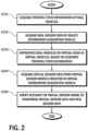
- FIG. 2 is a flowchart provided to explain a virtual sensor model verification method according to another embodiment.
- the sensor data synchronization module 110 may acquire information on positions and states of the real vehicles 10, 10-1, 10-2, ..., 10-n running on a real road (S210), first, and may acquire real sensor data from the reality information acquisition vehicle 10 (S220).
- the autonomous driving simulation module 120 may reproduce the real vehicles 10, 10-1, 10-2, ..., 10-n on a virtual road as virtual vehicles, based on the information on the positions and states acquired at step S210 (S230).
- the virtual sensor verification module 130 may acquire virtual sensor data from a virtual sensor model mounted in a virtual information acquisition vehicle, which corresponds to the reality information acquisition vehicle 10 (S240), and may verify accuracy of the virtual sensor model by comparing the acquired virtual sensor data with the real sensor data which is acquired at step S220 (S250).
- Data synchronization may be required to implement a virtual environment based on data acquired from the reality information acquisition vehicle 10 and the target vehicles 10-1, 10-1, ..., 10-n.
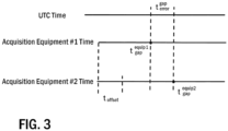
- a method for synchronizing data acquired from different real vehicles is illustrated in FIG. 3 .
- GNSS/INS data of a neighboring target vehicle are acquired with reference to a GPS time of the reality information acquisition vehicle 10 as shown in FIG. 3 .
- a time at which GNSS/INS data is acquired from the reality information acquisition vehicle 10 and a time at which GNSS/INS data is acquired from the neighboring target vehicle differ from each other.
- there may be a difference in time of starting to acquire GNSS/INS data and accordingly, a process of synchronizing data with reference to the reality information acquisition vehicle 10, which is an ego vehicle, is required.
- FIG. 3 illustrates an example of GNSS/INS data which is acquired by data acquisition equipment mounted in the reality information acquisition vehicle 10 and data acquisition equipment mounted in the neighboring target vehicle.
- time information of each piece of data acquisition equipment may be acquired, and GPS time data may be acquired.
- t gps 1 equip 1 , t gps 2 equip 2 that have a small time difference are extracted from GPS data which is acquired by acquisition equipment #1 [acquisition equipment of the reality information acquisition vehicle 10] and acquisition equipment #2 [acquisition equipment of the target vehicle 10-1, 10-2, ..., 10-n].
- t gps 1 equip 1 is a delay time resulting from GPS time data processing at acquisition equipment #1
- t gps 2 equip 2 is a delay time resulting from GPS time data processing at acquisition equipment #2.
- t gps 1 gps refers to a GPS reception delay time at acquisition equipment #1
- t gps 2 gps refers to a GPS reception delay time at acquisition equipment #2
- t gps 1 gps ⁇ t gps 2 gps equals t error gps and t ⁇ gps 2 equip 1 may be estimated by adding t error gps to t gps 1 equip 1
- t offset refers to a GPS time difference between acquisition equipment #1 and acquisition equipment #2.
- Real sensor data of the reality information acquisition vehicle 10 may be synchronized with reference to a GPS time of the reality information acquisition vehicle 10.
- the above-described embodiments propose a method for measuring and verifying accuracy of virtual sensor data to be supplied to a recognition, determination, control algorithm for autonomous driving when autonomous driving software mounted in an autonomous vehicle is verified based on a simulator.
- the technical concept of the present disclosure may be applied to a computer-readable recording medium which records a computer program for performing the functions of the apparatus and the method according to the present embodiments.
- the technical idea according to various embodiments of the present disclosure may be implemented in the form of a computer readable code recorded on the computer-readable recording medium.
- the computer-readable recording medium may be any data storage device that can be read by a computer and can store data.
- the computer-readable recording medium may be a read only memory (ROM), a random access memory (RAM), a CD-ROM, a magnetic tape, a floppy disk, an optical disk, a hard disk drive, or the like.
- a computer readable code or program that is stored in the computer readable recording medium may be transmitted via a network connected between computers.
Landscapes
- Engineering & Computer Science (AREA)
- Physics & Mathematics (AREA)
- General Physics & Mathematics (AREA)
- Theoretical Computer Science (AREA)
- Automation & Control Theory (AREA)
- Transportation (AREA)
- Mechanical Engineering (AREA)
- Human Computer Interaction (AREA)
- General Engineering & Computer Science (AREA)
- Quality & Reliability (AREA)
- Computer Hardware Design (AREA)
- Multimedia (AREA)
- Mathematical Physics (AREA)
- Artificial Intelligence (AREA)
- Medical Informatics (AREA)
- Computer Vision & Pattern Recognition (AREA)
- Computing Systems (AREA)
- Databases & Information Systems (AREA)
- Evolutionary Computation (AREA)
- General Health & Medical Sciences (AREA)
- Health & Medical Sciences (AREA)
- Software Systems (AREA)
- Computer Networks & Wireless Communication (AREA)
- Radar, Positioning & Navigation (AREA)
- Remote Sensing (AREA)
- Traffic Control Systems (AREA)
- Control Of Driving Devices And Active Controlling Of Vehicle (AREA)
- Image Analysis (AREA)
Abstract
There is a method for verifying accuracy of a virtual sensor model for simulation based on reality information data. According to an embodiment, a virtual sensor verification method may acquire information on positions and states of real vehicles which are running on a real road, may acquire real sensor data generated in real sensors of a reality information acquisition vehicle from among the real vehicles, may reproduce the real vehicles on a virtual road as virtual vehicles, based on the acquired information on the positions and states, may acquire virtual sensor data outputted from virtual sensors mounted in a virtual information acquisition vehicle from among the virtual vehicles, and may verify the virtual sensors by comparing the acquired real sensor data and the virtual sensor data. Accordingly, accuracy of virtual sensor data which is supplied to a recognition, determination, control algorithm for autonomous driving may be measured and verified, so that accuracy on a result of verifying based on a simulator of an autonomous driving algorithm may be enhanced.
Description
- This application is based on and claims priority under 35 U.S.C. § 119 to
Korean Patent Application No. 10-2022-0173316, filed on December 13, 2022 - The disclosure relates to an autonomous driving simulation, and more particularly, to a method for verifying accuracy of a virtual sensor model which is used for verifying an autonomous driving algorithm in a virtual road environment by using a simulator.
- An autonomous vehicle may have a sensor mounted therein to perform recognition, determination, and control, and may sense surroundings of the ego vehicle and may identify information of omnidirectional objects. In particular, an autonomous vehicle may recognize its surroundings, such as objects around the vehicle, a drivable region on a road, a traffic signal state, etc., from sensor data of a camera, a LiDAR, a RADAR, etc. mounted therein, may determine a moving direction of a neighboring object, a current drivable status, etc., and may control a movement of the ego vehicle.
- In order to verify an autonomous driving algorithm mounted in an autonomous vehicle, a simulator-based method may be used in parallel with real vehicle-based verification for rapid and effective verification. Various sensor data required to perform operations of a recognition, determination, and control algorithm mounted in an autonomous vehicle may be generated by modeling and simulating a virtual sensor, and may be provided to the algorithm. Accordingly, it is very important to maintain accuracy of an output value of a virtual sensor model which is used in an autonomous driving simulator for accurate operations of an algorithm.
- The disclosure has been developed in order to solve the above-described problems, and an object of the disclosure is to provide a method for measuring and verifying accuracy of virtual sensor data which is supplied to a recognition, determination, control algorithm for autonomous driving when autonomous driving software mounted in an autonomous vehicle is verified based on a simulator.
- According to an embodiment of the disclosure to achieve the above-described object, a virtual sensor verification method may include: acquiring information on positions and states of real vehicles which are running on a real road; acquiring real sensor data generated in real sensors of a reality information acquisition vehicle from among the real vehicles; reproducing the real vehicles on a virtual road as virtual vehicles, based on the acquired information on the positions and states; acquiring virtual sensor data outputted from virtual sensors mounted in a virtual information acquisition vehicle from among the virtual vehicles; and verifying the virtual sensors by comparing the acquired real sensor data and the virtual sensor data.
- The virtual sensors may be virtual sensors that simulate types and specifications of the real sensors.
- The real sensors may include a real camera, a real LiDAR, and a real RADAR, and the virtual sensors may include a virtual camera, a virtual LiDAR, and a virtual RADAR.
- The information on the positions and states of the real vehicles may be acquired from GNSS/INS mounted in the real vehicles.
- The GNSS/INS mounted in the real vehicles may be synchronized with reference to a GPS time of GNSS/INS mounted in the reality information acquisition vehicle.
- A difference between a GPS time of the reality information acquisition vehicle and a GPS time of a target vehicle may be calculated by the following equation:


- The real sensor data of the reality information acquisition vehicle may be synchronized with reference to a GPS time of the reality information acquisition vehicle.
- The virtual road may be a road that simulates a real road in a virtual space.
- A simulator may be a tool for testing an autonomous driving algorithm through the reality information acquisition vehicle.
- According to another aspect of the disclosure, a virtual sensor verification system may include: a synchronization module configured to acquire information on positions and states of real vehicles which are running on a real road, and to acquire real sensor data generated in real sensors of a reality information acquisition vehicle from among the real vehicles; a simulation module configured to reproduce the real vehicles on a virtual road as virtual vehicles, based on the acquired information on the positions and states; and a verification module configured to acquire virtual sensor data outputted from virtual sensors mounted in a virtual information acquisition vehicle from among the virtual vehicles, and to verify the virtual sensors by comparing the acquired real sensor data and the virtual sensor data.
- According to still another aspect of the disclosure, a virtual sensor verification method may include: reproducing real vehicles on a virtual road as virtual vehicles, based on information on positions and states which is acquired from real vehicles running on a real road; acquiring virtual sensor data outputted from virtual sensors mounted in a virtual information acquisition vehicle from among the virtual vehicles; and verifying the virtual sensors by comparing the acquired virtual sensor data and real sensor data which is acquired by real sensors of a reality information acquisition vehicle among the real vehicles.
- According to yet another aspect of the disclosure, a virtual sensor verification system may include: a simulation module configured to reproduce real vehicles on a virtual road as virtual vehicles, based on information on positions and states which is acquired from real vehicles running on a real road; and a verification module configured to acquire virtual sensor data outputted from virtual sensors mounted in a virtual information acquisition vehicle from among the virtual vehicles, and to verify the virtual sensors by comparing the acquired virtual sensor data and real sensor data which is acquired by real sensors of a reality information acquisition vehicle among the real vehicles.
- According to embodiments of the disclosure as described above, accuracy of virtual sensor data which is supplied to a recognition, determination, control algorithm for autonomous driving may be measured and verified, so that accuracy on a result of verifying based on a simulator of an autonomous driving algorithm may be enhanced.
- According to embodiments of the disclosure, it is possible to verify autonomous driving software based on a scenario of various environments and conditions, so that algorithms may be rapidly developed and stability of algorithms may be enhanced.
- Other aspects, advantages, and salient features of the invention will become apparent to those skilled in the art from the following detailed description, which, taken in conjunction with the annexed drawings, discloses exemplary embodiments of the invention.
- Before undertaking the DETAILED DESCRIPTION OF THE INVENTION below, it may be advantageous to set forth definitions of certain words and phrases used throughout this patent document: the terms "include" and "comprise," as well as derivatives thereof, mean inclusion without limitation; the term "or," is inclusive, meaning and/or; the phrases "associated with" and "associated therewith," as well as derivatives thereof, may mean to include, be included within, interconnect with, contain, be contained within, connect to or with, couple to or with, be communicable with, cooperate with, interleave, juxtapose, be proximate to, be bound to or with, have, have a property of, or the like. Definitions for certain words and phrases are provided throughout this patent document, those of ordinary skill in the art should understand that in many, if not most instances, such definitions apply to prior, as well as future uses of such defined words and phrases.
- For a more complete understanding of the present disclosure and its advantages, reference is now made to the following description taken in conjunction with the accompanying drawings, in which like reference numerals represent like parts:
-
FIG. 1 is a view illustrating a configuration of a virtual sensor model verification system according to an embodiment of the disclosure; -
FIG. 2 is a flowchart provided to explain a virtual sensor model verification method according to another embodiment of the disclosure; and -
FIG. 3 is a view illustrating a method of synchronizing data acquired from real vehicles. - Hereinafter, the disclosure will be described in more detail with reference to the accompanying drawings.
- An embodiment of the disclosure proposes a method for verifying accuracy of a virtual sensor model for simulation based on reality information data. The disclosure relates to a technology for measuring and verifying accuracy of a virtual sensor model which is used for verifying an autonomous driving algorithm in a virtual road environment using a simulator.
-
FIG. 1 is a view illustrating a configuration of a virtual sensor model verification system according to an embodiment of the disclosure. The virtual sensor model verification system according to an embodiment may include a sensordata synchronization module 110, an autonomousdriving simulation module 120, a virtualsensor verification module 130 as shown inFIG. 1 . - The sensor
data synchronization module 110 may receive data fromreal vehicles 10, 10-1, 10-2, ..., 10-n that are running on a real road, and may synchronize data. Thereal vehicles 10, 10-1, 10-2, ..., 10-n may be divided into a realityinformation acquisition vehicle 10 and target vehicles 10-1, 10-2, ..., 10-n. - The reality
information acquisition vehicle 10 is an ego vehicle which is an object for generating real sensor data, and the target vehicles 10-1, 10-2, ..., 10-n refer to vehicles thar are running around the realityinformation acquisition vehicle 10. - Data collected from the reality
information acquisition vehicle 10 may include global navigation satellite system (GNSS)/inertial navigation system (INS) data and real sensor data. On the other hand, the target vehicles 10-1, 10-2, ..., 10-n provide only GNSS/INS data. - The GNSS/INS data may contain information on positions and states (positions, direction, speeds of vehicles, etc.) of the
real vehicles 10, 10-1, 10-2, ..., 10-n. Real sensors installed in the realityinformation acquisition vehicle 10 may include a camera, a LiDAR, a RADAR, and may further include other types of sensors. - Accordingly, the sensor
data synchronization module 110 may receive GNSS/INS data and real sensor data from the realityinformation acquisition vehicle 10, and may receive GNSS/INS data from the target vehicles 10-1, 10-2, ..., 10-n, and may synchronize the received data. A method for synchronizing by the sensordata synchronization module 110 will be described in detail below with reference toFIG. 3 . - The autonomous
driving simulation module 120 may reproduce thereal vehicles 10, 10-1, 10-2, ..., 10-n on a virtual road as virtual vehicles, based on information on positions and states of thereal vehicles 10, 10-1, 10-2, ..., 10-n which is recorded on the GNSS/INS data transmitted through the sensordata synchronization module 110. - An autonomous driving simulation is a tool for testing an autonomous driving algorithm in a virtual environment through a virtual vehicle. The virtual road is a road in a virtual space, which simulates a real road.
- A virtual information acquisition vehicle which is a virtual vehicle corresponding to the reality
information acquisition vehicle 10 among the virtual vehicles may have virtual sensor models mounted therein. The virtual sensor models are virtual sensors that simulate real sensors installed in the realityinformation acquisition vehicle 10 to be of the same type and to have the same specification. - The virtual
sensor verification module 130 may verify accuracy of a virtual sensor model mounted in the virtual information acquisition vehicle by comparing real sensor data and virtual sensor data. Real sensor data may be acquired from the realityinformation acquisition vehicle 10 through the sensordata synchronization module 110, and virtual sensor data may be acquired from the autonomousdriving simulation module 120. -
FIG. 2 is a flowchart provided to explain a virtual sensor model verification method according to another embodiment. - In order to verify a virtual sensor model, the sensor
data synchronization module 110 may acquire information on positions and states of thereal vehicles 10, 10-1, 10-2, ..., 10-n running on a real road (S210), first, and may acquire real sensor data from the reality information acquisition vehicle 10 (S220). - The autonomous
driving simulation module 120 may reproduce thereal vehicles 10, 10-1, 10-2, ..., 10-n on a virtual road as virtual vehicles, based on the information on the positions and states acquired at step S210 (S230). - The virtual
sensor verification module 130 may acquire virtual sensor data from a virtual sensor model mounted in a virtual information acquisition vehicle, which corresponds to the reality information acquisition vehicle 10 (S240), and may verify accuracy of the virtual sensor model by comparing the acquired virtual sensor data with the real sensor data which is acquired at step S220 (S250). - Hereinafter, a method for synchronizing by the sensor
data synchronization module 110 described above will be described in detail. - Data synchronization may be required to implement a virtual environment based on data acquired from the reality
information acquisition vehicle 10 and the target vehicles 10-1, 10-1, ..., 10-n. A method for synchronizing data acquired from different real vehicles is illustrated inFIG. 3 . - It is assumed that GNSS/INS data of a neighboring target vehicle are acquired with reference to a GPS time of the reality
information acquisition vehicle 10 as shown inFIG. 3 . There is a high possibility that a time at which GNSS/INS data is acquired from the realityinformation acquisition vehicle 10 and a time at which GNSS/INS data is acquired from the neighboring target vehicle differ from each other. In addition, there may be a difference in time of starting to acquire GNSS/INS data, and accordingly, a process of synchronizing data with reference to the realityinformation acquisition vehicle 10, which is an ego vehicle, is required. -
FIG. 3 illustrates an example of GNSS/INS data which is acquired by data acquisition equipment mounted in the realityinformation acquisition vehicle 10 and data acquisition equipment mounted in the neighboring target vehicle. In order to compare by UTC time, time information of each piece of data acquisition equipment may be acquired, and GPS time data may be acquired. - A method of calculating toffset to extract accurate comparison data by synchronizing sensor data acquired from different pieces of equipment is based on the following equation:

- In the above equation,
data 

acquisition equipment # 1, and
acquisition equipment # 2. - In addition,

acquisition equipment # 1, and
acquisition equipment # 2.
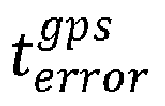


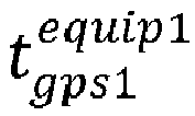
acquisition equipment # 1 andacquisition equipment # 2. - Real sensor data of the reality
information acquisition vehicle 10 may be synchronized with reference to a GPS time of the realityinformation acquisition vehicle 10. - Up to now, a method for verifying accuracy of a virtual sensor model for a simulation based on reality information data has been described with reference to preferred embodiments.
- The above-described embodiments propose a method for measuring and verifying accuracy of virtual sensor data to be supplied to a recognition, determination, control algorithm for autonomous driving when autonomous driving software mounted in an autonomous vehicle is verified based on a simulator.
- Accordingly, it is expected that accuracy on a result of verifying based on a simulator of an autonomous driving algorithm and a recognition, determination, control algorithm mounted in an autonomous vehicle is enhanced, and it is possible to verify autonomous driving software based on a scenario of various environments and conditions, so that algorithms may be rapidly developed and stability of algorithms may be enhanced.
- The technical concept of the present disclosure may be applied to a computer-readable recording medium which records a computer program for performing the functions of the apparatus and the method according to the present embodiments. In addition, the technical idea according to various embodiments of the present disclosure may be implemented in the form of a computer readable code recorded on the computer-readable recording medium. The computer-readable recording medium may be any data storage device that can be read by a computer and can store data. For example, the computer-readable recording medium may be a read only memory (ROM), a random access memory (RAM), a CD-ROM, a magnetic tape, a floppy disk, an optical disk, a hard disk drive, or the like. A computer readable code or program that is stored in the computer readable recording medium may be transmitted via a network connected between computers.
- In addition, while preferred embodiments of the present disclosure have been illustrated and described, the present disclosure is not limited to the above-described specific embodiments. Various changes can be made by a person skilled in the at without departing from the scope of the present disclosure claimed in claims, and also, changed embodiments should not be understood as being separate from the technical idea or prospect of the present disclosure.
Claims (11)
- A virtual sensor verification method comprising:acquiring information on positions and states of real vehicles which are running on a real road;acquiring real sensor data generated in real sensors of a reality information acquisition vehicle from among the real vehicles;reproducing the real vehicles on a virtual road as virtual vehicles, based on the acquired information on the positions and states;acquiring virtual sensor data outputted from virtual sensors mounted in a virtual information acquisition vehicle from among the virtual vehicles; andverifying the virtual sensors by comparing the acquired real sensor data and the virtual sensor data.
- The virtual sensor verification method of claim 1, wherein the virtual sensors are virtual sensors that simulate types and specifications of the real sensors.
- The virtual sensor verification method of claim 1, wherein the real sensors comprise a real camera, a real LiDAR, and a real RADAR, and
wherein the virtual sensors comprise a virtual camera, a virtual LiDAR, and a virtual RADAR. - The virtual sensor verification method of claim 1, wherein the information on the positions and states of the real vehicles are acquired from GNSS/INS mounted in the real vehicles.
- The virtual sensor verification method of claim 4, wherein the GNSS/INS mounted in the real vehicles are synchronized with reference to a GPS time of GNSS/INS mounted in the reality information acquisition vehicle.
- The virtual sensor verification method of claim 5, wherein a difference between a GPS time of the reality information acquisition vehicle and a GPS time of a target vehicle is calculated by the following equation:


- The virtual sensor verification method of claim 5, wherein the real sensor data of the reality information acquisition vehicle is synchronized with reference to a GPS time of the reality information acquisition vehicle.
- The virtual sensor verification method of claim 1, wherein the virtual road is a road that simulates a real road in a virtual space.
- The virtual sensor verification method of claim 1, wherein a simulator is a tool for testing an autonomous driving algorithm through the reality information acquisition vehicle.
- A virtual sensor verification system comprising:a synchronization module configured to acquire information on positions and states of real vehicles which are running on a real road, and to acquire real sensor data generated in real sensors of a reality information acquisition vehicle from among the real vehicles;a simulation module configured to reproduce the real vehicles on a virtual road as virtual vehicles, based on the acquired information on the positions and states; anda verification module configured to acquire virtual sensor data outputted from virtual sensors mounted in a virtual information acquisition vehicle from among the virtual vehicles, and to verify the virtual sensors by comparing the acquired real sensor data and the virtual sensor data.
- A virtual sensor verification method comprising:reproducing real vehicles on a virtual road as virtual vehicles, based on information on positions and states which is acquired from real vehicles running on a real road;acquiring virtual sensor data outputted from virtual sensors mounted in a virtual information acquisition vehicle from among the virtual vehicles; andverifying the virtual sensors by comparing the acquired virtual sensor data and real sensor data which is acquired by real sensors of a reality information acquisition vehicle among the real vehicles.
Applications Claiming Priority (1)
| Application Number | Priority Date | Filing Date | Title |
|---|---|---|---|
| KR1020220173316A KR20240090045A (en) | 2022-12-13 | 2022-12-13 | Accuracy verification method of virtual sensor model for simulation based on real information data |
Publications (1)
| Publication Number | Publication Date |
|---|---|
| EP4386561A1 true EP4386561A1 (en) | 2024-06-19 |
Family
ID=88833963
Family Applications (1)
| Application Number | Title | Priority Date | Filing Date |
|---|---|---|---|
| EP23209401.1A Pending EP4386561A1 (en) | 2022-12-13 | 2023-11-13 | Method for verifying accuracy of virtual sensor model for simulation based on reality information data |
Country Status (4)
| Country | Link |
|---|---|
| US (1) | US20240194005A1 (en) |
| EP (1) | EP4386561A1 (en) |
| JP (1) | JP7675152B2 (en) |
| KR (1) | KR20240090045A (en) |
Families Citing this family (1)
| Publication number | Priority date | Publication date | Assignee | Title |
|---|---|---|---|---|
| US20230281354A1 (en) * | 2022-03-07 | 2023-09-07 | Woven By Toyota, Inc. | System and method for providing autonomous driving simulation architecture with switchable models |
Citations (2)
| Publication number | Priority date | Publication date | Assignee | Title |
|---|---|---|---|---|
| CN114614934A (en) * | 2022-03-28 | 2022-06-10 | 智己汽车科技有限公司 | Time synchronization triggering device and method |
| US20220374428A1 (en) * | 2021-05-24 | 2022-11-24 | Nvidia Corporation | Simulation query engine in autonomous machine applications |
Family Cites Families (16)
| Publication number | Priority date | Publication date | Assignee | Title |
|---|---|---|---|---|
| US6813561B2 (en) * | 2003-03-25 | 2004-11-02 | Ford Global Technologies, Llc | Relative positioning for vehicles using GPS enhanced with bluetooth range finding |
| US20090043435A1 (en) * | 2007-08-07 | 2009-02-12 | Quantum Engineering, Inc. | Methods and systems for making a gps signal vital |
| US9715004B2 (en) * | 2009-10-05 | 2017-07-25 | Bae Systems Plc | Radio positioning of a mobile receiver using a virtual positioning reference |
| US9285485B2 (en) * | 2009-11-12 | 2016-03-15 | GM Global Technology Operations LLC | GPS-enhanced vehicle velocity estimation |
| US9187118B2 (en) * | 2011-12-30 | 2015-11-17 | C & P Technologies, Inc. | Method and apparatus for automobile accident reduction using localized dynamic swarming |
| FR3018941B1 (en) * | 2014-03-21 | 2017-07-07 | Thales Sa | PILOTAGE OF VEHICLES IN CONVOI |
| US11370422B2 (en) * | 2015-02-12 | 2022-06-28 | Honda Research Institute Europe Gmbh | Method and system in a vehicle for improving prediction results of an advantageous driver assistant system |
| US10481044B2 (en) * | 2017-05-18 | 2019-11-19 | TuSimple | Perception simulation for improved autonomous vehicle control |
| JP2019053503A (en) * | 2017-09-14 | 2019-04-04 | 本田技研工業株式会社 | Mobile object information acquisition system, mobile object information acquisition method, program, and mobile object |
| US20190130739A1 (en) * | 2017-10-31 | 2019-05-02 | V-Synchronize Tech LLC | Self synchronization of moving vehicles |
| US11127373B2 (en) * | 2019-10-30 | 2021-09-21 | Ford Global Technologies, Llc | Augmented reality wearable system for vehicle occupants |
| US20220204009A1 (en) * | 2020-12-29 | 2022-06-30 | Waymo Llc | Simulations of sensor behavior in an autonomous vehicle |
| US12007487B1 (en) * | 2020-12-31 | 2024-06-11 | Waymo Llc | Global positioning system time verification for autonomous vehicles |
| US11481926B2 (en) * | 2021-03-08 | 2022-10-25 | Gm Cruise Holdings Llc | Vehicle analysis environment with displays for vehicle sensor calibration and/or event simulation |
| US20230202507A1 (en) * | 2021-12-22 | 2023-06-29 | Gm Cruise Holdings Llc | Control system for autonomous vehicle simulator |
| US12217323B2 (en) * | 2022-03-31 | 2025-02-04 | Amazon Technologies, Inc. | Vehicle data jurisdiction management |
-
2022
- 2022-12-13 KR KR1020220173316A patent/KR20240090045A/en not_active Ceased
-
2023
- 2023-10-31 JP JP2023186429A patent/JP7675152B2/en active Active
- 2023-11-13 US US18/388,915 patent/US20240194005A1/en active Pending
- 2023-11-13 EP EP23209401.1A patent/EP4386561A1/en active Pending
Patent Citations (2)
| Publication number | Priority date | Publication date | Assignee | Title |
|---|---|---|---|---|
| US20220374428A1 (en) * | 2021-05-24 | 2022-11-24 | Nvidia Corporation | Simulation query engine in autonomous machine applications |
| CN114614934A (en) * | 2022-03-28 | 2022-06-10 | 智己汽车科技有限公司 | Time synchronization triggering device and method |
Also Published As
| Publication number | Publication date |
|---|---|
| JP2024084692A (en) | 2024-06-25 |
| JP7675152B2 (en) | 2025-05-12 |
| US20240194005A1 (en) | 2024-06-13 |
| KR20240090045A (en) | 2024-06-21 |
Similar Documents
| Publication | Publication Date | Title |
|---|---|---|
| CN109194436B (en) | Sensor timestamp synchronous testing method, device, equipment, medium and vehicle | |
| EP3644015A1 (en) | Position estimation system and position estimation method | |
| EP3943983A1 (en) | Positioning method, device, medium and equipment | |
| EP4336367A1 (en) | Vil system based autonomous driving function verification method | |
| CN111797526B (en) | Simulation test scene construction method and device | |
| EP3872633A1 (en) | Autonomous driving vehicle simulation method in virtual environment | |
| CN115016323A (en) | Simulation test system and method for autonomous driving | |
| EP2657644A1 (en) | Positioning apparatus and positioning method | |
| US10410072B2 (en) | Driving support apparatus, driving support system, driving support method, and computer readable recording medium | |
| CN114705186B (en) | Combined navigation verification method and device, terminal equipment and readable medium | |
| CN111177887A (en) | Method and device for constructing simulation track data based on real driving scene | |
| EP3789797B1 (en) | Method and apparatus for evaluating data, device, and computer-readable storage medium | |
| CN116182905B (en) | Spatiotemporal extrinsic parameter calibration methods, devices and systems for lidar and combined inertial navigation | |
| US20240194005A1 (en) | Method for verifying accuracy of virtual sensor model for simulation based on reality information data | |
| CN113758492A (en) | Map detection method and device | |
| JP6980497B2 (en) | Information processing method and information processing equipment | |
| US12571651B2 (en) | Method and apparatus for providing a high-resolution digital map | |
| EP4290491A1 (en) | Simulated road generation system, simulated road generation method, and non-transitory computer-readable medium having stored thereon program for causing computer to perform simulated road generation process | |
| CN112629547A (en) | Method and apparatus for creating positioning map | |
| US20230267238A1 (en) | Navigation simulator, information processing device, and recording medium | |
| CN113640760B (en) | Radar discovery probability evaluation method and equipment based on air situation data | |
| CN116007958A (en) | ADAS test evaluation method and system based on truth system | |
| KR20230094504A (en) | Vehicle-in-the-Loop system and method for interworking between simulator and real vehicle | |
| CN120387324B (en) | Real vehicle data reinjection method, electronic equipment, storage medium and program product | |
| EP4528326A1 (en) | Methodology to provide assurance of data association in navigation and radar systems |
Legal Events
| Date | Code | Title | Description |
|---|---|---|---|
| PUAI | Public reference made under article 153(3) epc to a published international application that has entered the european phase |
Free format text: ORIGINAL CODE: 0009012 |
|
| STAA | Information on the status of an ep patent application or granted ep patent |
Free format text: STATUS: REQUEST FOR EXAMINATION WAS MADE |
|
| 17P | Request for examination filed |
Effective date: 20231113 |
|
| AK | Designated contracting states |
Kind code of ref document: A1 Designated state(s): AL AT BE BG CH CY CZ DE DK EE ES FI FR GB GR HR HU IE IS IT LI LT LU LV MC ME MK MT NL NO PL PT RO RS SE SI SK SM TR |
|
| RBV | Designated contracting states (corrected) |
Designated state(s): AL AT BE BG CH CY CZ DE DK EE ES FI FR GB GR HR HU IE IS IT LI LT LU LV MC ME MK MT NL NO PL PT RO RS SE SI SK SM TR |