EP4386529A1 - Input display device - Google Patents
Input display device Download PDFInfo
- Publication number
- EP4386529A1 EP4386529A1 EP23214419.6A EP23214419A EP4386529A1 EP 4386529 A1 EP4386529 A1 EP 4386529A1 EP 23214419 A EP23214419 A EP 23214419A EP 4386529 A1 EP4386529 A1 EP 4386529A1
- Authority
- EP
- European Patent Office
- Prior art keywords
- unit
- dimensional
- display device
- face
- side face
- Prior art date
- Legal status (The legal status is an assumption and is not a legal conclusion. Google has not performed a legal analysis and makes no representation as to the accuracy of the status listed.)
- Pending
Links
Images




Classifications
-
- G—PHYSICS
- G06—COMPUTING OR CALCULATING; COUNTING
- G06F—ELECTRIC DIGITAL DATA PROCESSING
- G06F3/00—Input arrangements for transferring data to be processed into a form capable of being handled by the computer; Output arrangements for transferring data from processing unit to output unit, e.g. interface arrangements
- G06F3/01—Input arrangements or combined input and output arrangements for interaction between user and computer
- G06F3/03—Arrangements for converting the position or the displacement of a member into a coded form
- G06F3/041—Digitisers, e.g. for touch screens or touch pads, characterised by the transducing means
- G06F3/0416—Control or interface arrangements specially adapted for digitisers
- G06F3/0418—Control or interface arrangements specially adapted for digitisers for error correction or compensation, e.g. based on parallax, calibration or alignment
- G06F3/04186—Touch location disambiguation
-
- G—PHYSICS
- G06—COMPUTING OR CALCULATING; COUNTING
- G06F—ELECTRIC DIGITAL DATA PROCESSING
- G06F3/00—Input arrangements for transferring data to be processed into a form capable of being handled by the computer; Output arrangements for transferring data from processing unit to output unit, e.g. interface arrangements
- G06F3/01—Input arrangements or combined input and output arrangements for interaction between user and computer
- G06F3/03—Arrangements for converting the position or the displacement of a member into a coded form
- G06F3/033—Pointing devices displaced or positioned by the user, e.g. mice, trackballs, pens or joysticks; Accessories therefor
- G06F3/0362—Pointing devices displaced or positioned by the user, e.g. mice, trackballs, pens or joysticks; Accessories therefor with detection of one-dimensional [1D] translations or rotations of an operating part of the device, e.g. scroll wheels, sliders, knobs, rollers or belts
-
- B—PERFORMING OPERATIONS; TRANSPORTING
- B60—VEHICLES IN GENERAL
- B60K—ARRANGEMENT OR MOUNTING OF PROPULSION UNITS OR OF TRANSMISSIONS IN VEHICLES; ARRANGEMENT OR MOUNTING OF PLURAL DIVERSE PRIME-MOVERS IN VEHICLES; AUXILIARY DRIVES FOR VEHICLES; INSTRUMENTATION OR DASHBOARDS FOR VEHICLES; ARRANGEMENTS IN CONNECTION WITH COOLING, AIR INTAKE, GAS EXHAUST OR FUEL SUPPLY OF PROPULSION UNITS IN VEHICLES
- B60K35/00—Instruments specially adapted for vehicles; Arrangement of instruments in or on vehicles
-
- B—PERFORMING OPERATIONS; TRANSPORTING
- B60—VEHICLES IN GENERAL
- B60K—ARRANGEMENT OR MOUNTING OF PROPULSION UNITS OR OF TRANSMISSIONS IN VEHICLES; ARRANGEMENT OR MOUNTING OF PLURAL DIVERSE PRIME-MOVERS IN VEHICLES; AUXILIARY DRIVES FOR VEHICLES; INSTRUMENTATION OR DASHBOARDS FOR VEHICLES; ARRANGEMENTS IN CONNECTION WITH COOLING, AIR INTAKE, GAS EXHAUST OR FUEL SUPPLY OF PROPULSION UNITS IN VEHICLES
- B60K35/00—Instruments specially adapted for vehicles; Arrangement of instruments in or on vehicles
- B60K35/20—Output arrangements, i.e. from vehicle to user, associated with vehicle functions or specially adapted therefor
- B60K35/21—Output arrangements, i.e. from vehicle to user, associated with vehicle functions or specially adapted therefor using visual output, e.g. blinking lights or matrix displays
- B60K35/211—Output arrangements, i.e. from vehicle to user, associated with vehicle functions or specially adapted therefor using visual output, e.g. blinking lights or matrix displays producing three-dimensional [3D] effects, e.g. stereoscopic images
-
- B—PERFORMING OPERATIONS; TRANSPORTING
- B60—VEHICLES IN GENERAL
- B60K—ARRANGEMENT OR MOUNTING OF PROPULSION UNITS OR OF TRANSMISSIONS IN VEHICLES; ARRANGEMENT OR MOUNTING OF PLURAL DIVERSE PRIME-MOVERS IN VEHICLES; AUXILIARY DRIVES FOR VEHICLES; INSTRUMENTATION OR DASHBOARDS FOR VEHICLES; ARRANGEMENTS IN CONNECTION WITH COOLING, AIR INTAKE, GAS EXHAUST OR FUEL SUPPLY OF PROPULSION UNITS IN VEHICLES
- B60K35/00—Instruments specially adapted for vehicles; Arrangement of instruments in or on vehicles
- B60K35/20—Output arrangements, i.e. from vehicle to user, associated with vehicle functions or specially adapted therefor
- B60K35/21—Output arrangements, i.e. from vehicle to user, associated with vehicle functions or specially adapted therefor using visual output, e.g. blinking lights or matrix displays
- B60K35/212—Output arrangements, i.e. from vehicle to user, associated with vehicle functions or specially adapted therefor using visual output, e.g. blinking lights or matrix displays displaying on manual operation elements, e.g. on a knob
-
- G—PHYSICS
- G06—COMPUTING OR CALCULATING; COUNTING
- G06F—ELECTRIC DIGITAL DATA PROCESSING
- G06F1/00—Details not covered by groups G06F3/00 - G06F13/00 and G06F21/00
- G06F1/16—Constructional details or arrangements
- G06F1/1601—Constructional details related to the housing of computer displays, e.g. of CRT monitors, of flat displays
- G06F1/1603—Arrangements to protect the display from incident light, e.g. hoods
-
- G—PHYSICS
- G06—COMPUTING OR CALCULATING; COUNTING
- G06F—ELECTRIC DIGITAL DATA PROCESSING
- G06F3/00—Input arrangements for transferring data to be processed into a form capable of being handled by the computer; Output arrangements for transferring data from processing unit to output unit, e.g. interface arrangements
- G06F3/01—Input arrangements or combined input and output arrangements for interaction between user and computer
- G06F3/011—Arrangements for interaction with the human body, e.g. for user immersion in virtual reality
- G06F3/012—Head tracking input arrangements
-
- G—PHYSICS
- G06—COMPUTING OR CALCULATING; COUNTING
- G06F—ELECTRIC DIGITAL DATA PROCESSING
- G06F3/00—Input arrangements for transferring data to be processed into a form capable of being handled by the computer; Output arrangements for transferring data from processing unit to output unit, e.g. interface arrangements
- G06F3/01—Input arrangements or combined input and output arrangements for interaction between user and computer
- G06F3/011—Arrangements for interaction with the human body, e.g. for user immersion in virtual reality
- G06F3/013—Eye tracking input arrangements
-
- G—PHYSICS
- G06—COMPUTING OR CALCULATING; COUNTING
- G06F—ELECTRIC DIGITAL DATA PROCESSING
- G06F3/00—Input arrangements for transferring data to be processed into a form capable of being handled by the computer; Output arrangements for transferring data from processing unit to output unit, e.g. interface arrangements
- G06F3/01—Input arrangements or combined input and output arrangements for interaction between user and computer
- G06F3/03—Arrangements for converting the position or the displacement of a member into a coded form
- G06F3/033—Pointing devices displaced or positioned by the user, e.g. mice, trackballs, pens or joysticks; Accessories therefor
- G06F3/039—Accessories therefor, e.g. mouse pads
- G06F3/0393—Accessories for touch pads or touch screens, e.g. mechanical guides added to touch screens for drawing straight lines, hard keys overlaying touch screens or touch pads
-
- G—PHYSICS
- G06—COMPUTING OR CALCULATING; COUNTING
- G06F—ELECTRIC DIGITAL DATA PROCESSING
- G06F3/00—Input arrangements for transferring data to be processed into a form capable of being handled by the computer; Output arrangements for transferring data from processing unit to output unit, e.g. interface arrangements
- G06F3/01—Input arrangements or combined input and output arrangements for interaction between user and computer
- G06F3/03—Arrangements for converting the position or the displacement of a member into a coded form
- G06F3/041—Digitisers, e.g. for touch screens or touch pads, characterised by the transducing means
- G06F3/044—Digitisers, e.g. for touch screens or touch pads, characterised by the transducing means by capacitive means
-
- G—PHYSICS
- G06—COMPUTING OR CALCULATING; COUNTING
- G06F—ELECTRIC DIGITAL DATA PROCESSING
- G06F3/00—Input arrangements for transferring data to be processed into a form capable of being handled by the computer; Output arrangements for transferring data from processing unit to output unit, e.g. interface arrangements
- G06F3/01—Input arrangements or combined input and output arrangements for interaction between user and computer
- G06F3/048—Interaction techniques based on graphical user interfaces [GUI]
- G06F3/0484—Interaction techniques based on graphical user interfaces [GUI] for the control of specific functions or operations, e.g. selecting or manipulating an object, an image or a displayed text element, setting a parameter value or selecting a range
- G06F3/04847—Interaction techniques to control parameter settings, e.g. interaction with sliders or dials
-
- G—PHYSICS
- G06—COMPUTING OR CALCULATING; COUNTING
- G06F—ELECTRIC DIGITAL DATA PROCESSING
- G06F3/00—Input arrangements for transferring data to be processed into a form capable of being handled by the computer; Output arrangements for transferring data from processing unit to output unit, e.g. interface arrangements
- G06F3/01—Input arrangements or combined input and output arrangements for interaction between user and computer
- G06F3/048—Interaction techniques based on graphical user interfaces [GUI]
- G06F3/0487—Interaction techniques based on graphical user interfaces [GUI] using specific features provided by the input device, e.g. functions controlled by the rotation of a mouse with dual sensing arrangements, or of the nature of the input device, e.g. tap gestures based on pressure sensed by a digitiser
- G06F3/0488—Interaction techniques based on graphical user interfaces [GUI] using specific features provided by the input device, e.g. functions controlled by the rotation of a mouse with dual sensing arrangements, or of the nature of the input device, e.g. tap gestures based on pressure sensed by a digitiser using a touch-screen or digitiser, e.g. input of commands through traced gestures
- G06F3/04886—Interaction techniques based on graphical user interfaces [GUI] using specific features provided by the input device, e.g. functions controlled by the rotation of a mouse with dual sensing arrangements, or of the nature of the input device, e.g. tap gestures based on pressure sensed by a digitiser using a touch-screen or digitiser, e.g. input of commands through traced gestures by partitioning the display area of the touch-screen or the surface of the digitising tablet into independently controllable areas, e.g. virtual keyboards or menus
-
- B—PERFORMING OPERATIONS; TRANSPORTING
- B60—VEHICLES IN GENERAL
- B60K—ARRANGEMENT OR MOUNTING OF PROPULSION UNITS OR OF TRANSMISSIONS IN VEHICLES; ARRANGEMENT OR MOUNTING OF PLURAL DIVERSE PRIME-MOVERS IN VEHICLES; AUXILIARY DRIVES FOR VEHICLES; INSTRUMENTATION OR DASHBOARDS FOR VEHICLES; ARRANGEMENTS IN CONNECTION WITH COOLING, AIR INTAKE, GAS EXHAUST OR FUEL SUPPLY OF PROPULSION UNITS IN VEHICLES
- B60K2360/00—Indexing scheme associated with groups B60K35/00 or B60K37/00 relating to details of instruments or dashboards
- B60K2360/126—Rotatable input devices for instruments
-
- B—PERFORMING OPERATIONS; TRANSPORTING
- B60—VEHICLES IN GENERAL
- B60K—ARRANGEMENT OR MOUNTING OF PROPULSION UNITS OR OF TRANSMISSIONS IN VEHICLES; ARRANGEMENT OR MOUNTING OF PLURAL DIVERSE PRIME-MOVERS IN VEHICLES; AUXILIARY DRIVES FOR VEHICLES; INSTRUMENTATION OR DASHBOARDS FOR VEHICLES; ARRANGEMENTS IN CONNECTION WITH COOLING, AIR INTAKE, GAS EXHAUST OR FUEL SUPPLY OF PROPULSION UNITS IN VEHICLES
- B60K2360/00—Indexing scheme associated with groups B60K35/00 or B60K37/00 relating to details of instruments or dashboards
- B60K2360/143—Touch sensitive instrument input devices
- B60K2360/1434—Touch panels
-
- B—PERFORMING OPERATIONS; TRANSPORTING
- B60—VEHICLES IN GENERAL
- B60K—ARRANGEMENT OR MOUNTING OF PROPULSION UNITS OR OF TRANSMISSIONS IN VEHICLES; ARRANGEMENT OR MOUNTING OF PLURAL DIVERSE PRIME-MOVERS IN VEHICLES; AUXILIARY DRIVES FOR VEHICLES; INSTRUMENTATION OR DASHBOARDS FOR VEHICLES; ARRANGEMENTS IN CONNECTION WITH COOLING, AIR INTAKE, GAS EXHAUST OR FUEL SUPPLY OF PROPULSION UNITS IN VEHICLES
- B60K2360/00—Indexing scheme associated with groups B60K35/00 or B60K37/00 relating to details of instruments or dashboards
- B60K2360/145—Instrument input by combination of touch screen and hardware input devices
-
- B—PERFORMING OPERATIONS; TRANSPORTING
- B60—VEHICLES IN GENERAL
- B60K—ARRANGEMENT OR MOUNTING OF PROPULSION UNITS OR OF TRANSMISSIONS IN VEHICLES; ARRANGEMENT OR MOUNTING OF PLURAL DIVERSE PRIME-MOVERS IN VEHICLES; AUXILIARY DRIVES FOR VEHICLES; INSTRUMENTATION OR DASHBOARDS FOR VEHICLES; ARRANGEMENTS IN CONNECTION WITH COOLING, AIR INTAKE, GAS EXHAUST OR FUEL SUPPLY OF PROPULSION UNITS IN VEHICLES
- B60K2360/00—Indexing scheme associated with groups B60K35/00 or B60K37/00 relating to details of instruments or dashboards
- B60K2360/149—Instrument input by detecting viewing direction not otherwise provided for
-
- B—PERFORMING OPERATIONS; TRANSPORTING
- B60—VEHICLES IN GENERAL
- B60K—ARRANGEMENT OR MOUNTING OF PROPULSION UNITS OR OF TRANSMISSIONS IN VEHICLES; ARRANGEMENT OR MOUNTING OF PLURAL DIVERSE PRIME-MOVERS IN VEHICLES; AUXILIARY DRIVES FOR VEHICLES; INSTRUMENTATION OR DASHBOARDS FOR VEHICLES; ARRANGEMENTS IN CONNECTION WITH COOLING, AIR INTAKE, GAS EXHAUST OR FUEL SUPPLY OF PROPULSION UNITS IN VEHICLES
- B60K2360/00—Indexing scheme associated with groups B60K35/00 or B60K37/00 relating to details of instruments or dashboards
- B60K2360/16—Type of output information
- B60K2360/171—Vehicle or relevant part thereof displayed
-
- B—PERFORMING OPERATIONS; TRANSPORTING
- B60—VEHICLES IN GENERAL
- B60K—ARRANGEMENT OR MOUNTING OF PROPULSION UNITS OR OF TRANSMISSIONS IN VEHICLES; ARRANGEMENT OR MOUNTING OF PLURAL DIVERSE PRIME-MOVERS IN VEHICLES; AUXILIARY DRIVES FOR VEHICLES; INSTRUMENTATION OR DASHBOARDS FOR VEHICLES; ARRANGEMENTS IN CONNECTION WITH COOLING, AIR INTAKE, GAS EXHAUST OR FUEL SUPPLY OF PROPULSION UNITS IN VEHICLES
- B60K2360/00—Indexing scheme associated with groups B60K35/00 or B60K37/00 relating to details of instruments or dashboards
- B60K2360/20—Optical features of instruments
- B60K2360/21—Optical features of instruments using cameras
-
- B—PERFORMING OPERATIONS; TRANSPORTING
- B60—VEHICLES IN GENERAL
- B60K—ARRANGEMENT OR MOUNTING OF PROPULSION UNITS OR OF TRANSMISSIONS IN VEHICLES; ARRANGEMENT OR MOUNTING OF PLURAL DIVERSE PRIME-MOVERS IN VEHICLES; AUXILIARY DRIVES FOR VEHICLES; INSTRUMENTATION OR DASHBOARDS FOR VEHICLES; ARRANGEMENTS IN CONNECTION WITH COOLING, AIR INTAKE, GAS EXHAUST OR FUEL SUPPLY OF PROPULSION UNITS IN VEHICLES
- B60K2360/00—Indexing scheme associated with groups B60K35/00 or B60K37/00 relating to details of instruments or dashboards
- B60K2360/20—Optical features of instruments
- B60K2360/23—Optical features of instruments using reflectors
-
- B—PERFORMING OPERATIONS; TRANSPORTING
- B60—VEHICLES IN GENERAL
- B60K—ARRANGEMENT OR MOUNTING OF PROPULSION UNITS OR OF TRANSMISSIONS IN VEHICLES; ARRANGEMENT OR MOUNTING OF PLURAL DIVERSE PRIME-MOVERS IN VEHICLES; AUXILIARY DRIVES FOR VEHICLES; INSTRUMENTATION OR DASHBOARDS FOR VEHICLES; ARRANGEMENTS IN CONNECTION WITH COOLING, AIR INTAKE, GAS EXHAUST OR FUEL SUPPLY OF PROPULSION UNITS IN VEHICLES
- B60K2360/00—Indexing scheme associated with groups B60K35/00 or B60K37/00 relating to details of instruments or dashboards
- B60K2360/20—Optical features of instruments
- B60K2360/33—Illumination features
- B60K2360/336—Light guides
-
- B—PERFORMING OPERATIONS; TRANSPORTING
- B60—VEHICLES IN GENERAL
- B60K—ARRANGEMENT OR MOUNTING OF PROPULSION UNITS OR OF TRANSMISSIONS IN VEHICLES; ARRANGEMENT OR MOUNTING OF PLURAL DIVERSE PRIME-MOVERS IN VEHICLES; AUXILIARY DRIVES FOR VEHICLES; INSTRUMENTATION OR DASHBOARDS FOR VEHICLES; ARRANGEMENTS IN CONNECTION WITH COOLING, AIR INTAKE, GAS EXHAUST OR FUEL SUPPLY OF PROPULSION UNITS IN VEHICLES
- B60K35/00—Instruments specially adapted for vehicles; Arrangement of instruments in or on vehicles
- B60K35/10—Input arrangements, i.e. from user to vehicle, associated with vehicle functions or specially adapted therefor
-
- B—PERFORMING OPERATIONS; TRANSPORTING
- B60—VEHICLES IN GENERAL
- B60K—ARRANGEMENT OR MOUNTING OF PROPULSION UNITS OR OF TRANSMISSIONS IN VEHICLES; ARRANGEMENT OR MOUNTING OF PLURAL DIVERSE PRIME-MOVERS IN VEHICLES; AUXILIARY DRIVES FOR VEHICLES; INSTRUMENTATION OR DASHBOARDS FOR VEHICLES; ARRANGEMENTS IN CONNECTION WITH COOLING, AIR INTAKE, GAS EXHAUST OR FUEL SUPPLY OF PROPULSION UNITS IN VEHICLES
- B60K35/00—Instruments specially adapted for vehicles; Arrangement of instruments in or on vehicles
- B60K35/20—Output arrangements, i.e. from vehicle to user, associated with vehicle functions or specially adapted therefor
- B60K35/21—Output arrangements, i.e. from vehicle to user, associated with vehicle functions or specially adapted therefor using visual output, e.g. blinking lights or matrix displays
- B60K35/22—Display screens
-
- B—PERFORMING OPERATIONS; TRANSPORTING
- B60—VEHICLES IN GENERAL
- B60K—ARRANGEMENT OR MOUNTING OF PROPULSION UNITS OR OF TRANSMISSIONS IN VEHICLES; ARRANGEMENT OR MOUNTING OF PLURAL DIVERSE PRIME-MOVERS IN VEHICLES; AUXILIARY DRIVES FOR VEHICLES; INSTRUMENTATION OR DASHBOARDS FOR VEHICLES; ARRANGEMENTS IN CONNECTION WITH COOLING, AIR INTAKE, GAS EXHAUST OR FUEL SUPPLY OF PROPULSION UNITS IN VEHICLES
- B60K35/00—Instruments specially adapted for vehicles; Arrangement of instruments in or on vehicles
- B60K35/20—Output arrangements, i.e. from vehicle to user, associated with vehicle functions or specially adapted therefor
- B60K35/28—Output arrangements, i.e. from vehicle to user, associated with vehicle functions or specially adapted therefor characterised by the type of the output information, e.g. video entertainment or vehicle dynamics information; characterised by the purpose of the output information, e.g. for attracting the attention of the driver
-
- G—PHYSICS
- G06—COMPUTING OR CALCULATING; COUNTING
- G06F—ELECTRIC DIGITAL DATA PROCESSING
- G06F2203/00—Indexing scheme relating to G06F3/00 - G06F3/048
- G06F2203/041—Indexing scheme relating to G06F3/041 - G06F3/045
- G06F2203/04108—Touchless 2D- digitiser, i.e. digitiser detecting the X/Y position of the input means, finger or stylus, also when it does not touch, but is proximate to the digitiser's interaction surface without distance measurement in the Z direction
-
- G—PHYSICS
- G06—COMPUTING OR CALCULATING; COUNTING
- G06F—ELECTRIC DIGITAL DATA PROCESSING
- G06F2203/00—Indexing scheme relating to G06F3/00 - G06F3/048
- G06F2203/048—Indexing scheme relating to G06F3/048
- G06F2203/04809—Textured surface identifying touch areas, e.g. overlay structure for a virtual keyboard
Definitions
- the present invention relates to an input display device having a human-machine interface function, and more particularly to an input display device including a transparent three-dimensional operation unit.
- An input display device in which a protrusion is provided on a touch panel disposed to be superimposed on a display, and an image such as an operation icon is displayed at a position overlapping the protrusion (for example, JP 2020-190832 A ). The user performs an input by performing a touch operation on the protrusion.
- a user interface (hereinafter, referred to as a three-dimensional UI) in which a cover glass has an uneven shape so that a touch position is tactilely recognized and the touch position can be understood without gazing.
- Fig. 1A is an operation example of a conventional flat touch panel, and a user U visually recognizes an operation icon 12 displayed on a display 10 and performs an input by performing a touch operation on the position of the operation icon 12 (note in the example of Figure).
- Fig. 1B is an operation example of a touch panel having a three-dimensional UI
- Fig. 1C is a schematic cross-sectional view of the three-dimensional UI.
- a transparent cover lens 26 having an uneven shape is attached onto a touch panel 24, and a display 20 displays an operation icon 22 at a position overlapping the cover lens 26.
- the user U performs input by touching the cover lens 26 with a finger.
- a highly sensitive electrostatic sensor capable of sensing the electrostatic capacitance (distance) of the finger even when the finger is away from the sensor is used for the touch sensing, and the presence or absence of the touch can be determined even from on the thick cover lens 26. This makes it possible to reduce touch mistakes (operation error) under a situation where it is difficult to gaze at the in-vehicle display during driving.
- FIG. 2A illustrates an example in which a speaker icon 32 representing adjustment of a volume and a gauge (scale) 34 representing a rotation amount of a rotation operation on a knob 30 are displayed in a region where the cylindrical transparent knob (button) 30 is present.
- the user slides a side face of the knob 30 with a finger pad to perform a rotation operation, and checks a rotation amount with the gauge 34.
- the knob 30 does not actually rotate.
- the display area is limited within the range of the knob 30, the design in which the speaker icon 32 is enlarged is limited, and when the knob diameter is small, the gauge 34 is small, and sufficient visibility cannot be secured.
- the visibility of the speaker icon 32 and the gauge 34 can be secured when the knob 30 is viewed from the front.
- the speaker icon 32 and the gauge 34 become small, and the visibility is deteriorated.
- the display is disposed at the center of the vehicle, the line-of-sight position or the line-of-sight direction of the user such as the driver is in the obliquely right direction.
- An object of the present invention is to provide an input display device that improves visibility of an image displayed in a region where an operation unit having a three-dimensional shape is present.
- the invention relates to an input display device according to the appended claims. Embodiments are disclosed in the dependent claims.
- An input display device includes a display for displaying an image, and a capacitive touch panel attached to the display and including at least one transparent three-dimensional operation unit on a front face of the touch panel, a sensing unit configured to sense a touch operation including proximity to the touch panel, and a display control unit capable of displaying an image related to an operation in a region where the operation unit of the display is present, wherein the operation unit has an upper face and a side face connected to the upper face, and the side face has a function of reflecting an image related to the operation.
- the side face includes a mirror-finished face. In an embodiment, the side face includes a reflective film or a specular coating. In an embodiment, the side face includes a film having a reflective face on a back face side and a texture on a front face side.
- the input display device further includes a detection unit configured to detect a viewpoint or a line-of-sight direction of a user, wherein the display control unit changes an image related to the operation according to a viewpoint or a line-of-sight direction detected by the detection unit. In an embodiment, the display control unit extends an image reflected by the side face by extending an image related to the operation.
- the three-dimensional operation unit is a cylindrical knob, wherein the sensing unit senses a rotation amount on the knob, wherein the display control unit displays a gauge corresponding to the sensed rotation amount along an outer periphery of the knob, and wherein the side face of the knob reflects the gauge.
- the display is mounted on a vehicle, and wherein the detection unit detects a line-of-sight position of each of a driver and/or a passenger.
- the function of reflecting the image related to the operation is imparted to the side face of the operation unit having the three-dimensional shape, the visibility of the image related to the operation can be improved, and the expression of the image related to the operation can be diversified.
- An input display device of the present invention provides an interface between a person and a machine.
- the input display device of the present invention is not particularly limited, but is applied to, for example, an electronic device equipped with a display with a touch panel on which an operation unit having a three-dimensional shape is formed.
- the electronic device equipped with the display with a touch panel is, for example, an in-vehicle device having a navigation function, an audio visual function, a television function, and the like.
- FIG. 3 is a block diagram illustrating a configuration of an input display device according to the embodiment of the present invention.
- An input display device 100 of the present embodiment includes a display 110 for displaying an image and a video, a touch panel 120 including a capacitive sensor mounted on the display 110, a transparent three-dimensional UI unit (or an operation unit) 130 having one or a plurality of stereoscopic shapes attached to a front face of the touch panel 120, and a controller 140 that controls image display of the display 110, touch sensing of the touch panel 120, and the like.
- the display 110 is not particularly limited, but includes, for example, a liquid crystal panel or an organic EL panel, and displays image data provided from the controller 140.
- image data provided from the controller 140.
- a GUI image for example, various images such as icons and gauges
- a GUI image related to the operation of the three-dimensional UI unit 130 is displayed in the region where the three-dimensional UI unit 130 is present.
- the touch panel 120 includes, for example, a plurality of sensors (sensing units) formed at positions where a plurality of X-side and Y-side electrode lines intersect, and the sensors sense an electrostatic capacitance when a user's finger, hand, or the like approaches or comes into contact with the touch panel 120 or the three-dimensional UI unit 130.
- the touch panel 120 is mounted on the display 110 and provides an input interface for the user to make an input to an icon or the like displayed on the display 110.
- the touch panel 120 further includes one or more three-dimensional UI units 130 on the transparent panel.
- the three-dimensional UI unit 130 includes a transparent member having an uneven shape, and the shape, size, height, and the like thereof are not particularly limited. However, when a user's hand or finger approaches or comes into contact with the three-dimensional UI unit 130, the three-dimensional UI unit 130 is configured such that the electrostatic capacitance at that position changes.
- Fig. 3 illustrates an example in which four three-dimensional UI units 130 are attached to the lower portion of the touch panel 120.
- a GUI image such as an icon or a gauge representing an operation is displayed in a region where the three-dimensional UI unit 130 of the display 110 is present, and the user visually recognizes the GUI image and performs input via the three-dimensional UI unit 130.
- the three-dimensional UI unit 130 is, for example, a rectangular or columnar protruding knob or button, and is composed of, for example, a clear part (transparent member) such as glass, acrylic, or polycarbonate. However, characters, figures, and the like may be drawn on a portion of the front face of the three-dimensional UI unit 130 within a range not affecting the visibility of the GUI image displayed on the display 110.
- the three-dimensional UI unit 130 may be attached to the front face of the touch panel 120 at a predetermined position using, for example, a double-sided adhesive or may be integrally molded with a cover glass attached to the front face of the touch panel 120.
- Information regarding the position and shape of the three-dimensional UI unit 130 is registered in a memory or the like in the controller 140.
- the three-dimensional UI unit 130 is a cylindrical knob
- the coordinates of the center of the bottom face of the knob are registered as the information about the position.
- the radius or diameter of the bottom face, the radius or diameter of the front face, the height of the side face, and the like of the knob are registered as the information about the shape.
- the three-dimensional UI unit 130 is a rectangular parallelepiped knob
- coordinates of a position where diagonal lines of a rectangular bottom face intersect are registered as information about the position
- vertical and horizontal lengths of the bottom face, vertical and horizontal lengths of the front face, a height of the side face, and the like are registered as information about the shape.
- the controller 140 refers to the registered information about the position and shape of the three-dimensional UI unit 130 and determines whether the finger acts as a touch operation on the three-dimensional UI unit 130.
- the controller 140 includes hardware and/or software resources, and performs overall processing of the input display device using, for example, an arithmetic processing unit, a microcontroller including a ROM/RAM, or the like. For example, the controller performs display processing of the display 110, touch sensing or touch operation determination (sense touch position and finger distance, and determine whether a touch operation is performed) from an output value of the touch panel 120, and processing of video display/video switching according to the touch sensing or the touch operation determination.
- touch sensing or touch operation determination sense touch position and finger distance, and determine whether a touch operation is performed
- the controller 140 includes a touch sensing unit 150, an operation determination unit 160, and a display control unit 170.
- the touch sensing unit 150 drives the plurality of electrode lines on the X side and/or the Y side of the touch panel 120, measures the capacitance of the sensing unit of the driven electrode lines, senses the touch position based on the measurement result, and provides the sensing result to the operation determination unit 160.
- the operation determination unit 160 determines the presence or absence of a touch operation on the touch panel 120 or a touch operation on the three-dimensional UI unit 130 based on the measurement result of the touch sensing unit 150.
- the touch includes not only contact of the user's finger with the touch panel 120 or the three-dimensional UI unit 130 but also approach of the finger to the touch panel 120 or the three-dimensional UI unit 130.
- the operation determination unit 160 determines the presence or absence of the touch operation based on the change in electrostatic capacitance of the corresponding sensing unit, and similarly, when the user's finger touches or approaches the three-dimensional UI unit 130, the operation determination unit determines the presence or absence of the touch operation on the three-dimensional UI unit 130 based on the change in electrostatic capacitance of the corresponding sensing unit.
- the display control unit 170 displays an image and a video on the display 110, and displays a GUI image related to the operation of the three-dimensional UI unit 130 in a region where the three-dimensional UI unit 130 is present. In addition, the display control unit 170 switches an image to be displayed on the display 110 to another image in response to the operation determination unit 160 determining that a touch operation has been performed.
- Figs. 4A and 4B schematically illustrate the visual recognition of the GUI image displayed in the region where the conventional three-dimensional UI unit is present
- Figs. 4C and 4D schematically illustrate the visual recognition of the GUI image displayed in the region where the three-dimensional UI unit of the present embodiment is present.
- a cylindrical knob is exemplified as the three-dimensional UI unit
- a gauge is exemplified as the GUI image.
- the height of the side face of the three-dimensional UI unit is used, and a function of specularly reflecting the GUI image 180 is imparted to the side face 136.
- the three-dimensional UI unit 130 has a front face 132, a bottom face 134, and a side face 136 coupling the front face 132 and the bottom face 134, and a function of reflecting the GUI image 180 is added to part or the whole of the side face 136.
- the user visually recognizes the GUI image 180 by the light L1a, L2a reflected by the side face 136 of the three-dimensional UI unit 130 in addition to the light L1, L2 from the GUI image 180. Therefore, the display area of the GUI image 180 is extended as compared with that in the conventional case, and the visibility is improved.
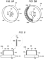
- Fig. 5A is an example when the GUI image (gauge) of the three-dimensional UI unit of the present embodiment is hidden
- Fig. 5B is an example when the GUI image (gauge) of the three-dimensional UI unit of the present embodiment is displayed.
- an example is illustrated in which, for more accurate specular reflection of the GUI image, the side face 136 of the three-dimensional UI unit 130 is vertical, and a transparent part (made of acrylic) having a specular finish is used for the side face 136.
- a volume icon 182 is displayed substantially at the center of the region where the three-dimensional UI unit 130 is present.
- the gauge indicating the rotation amount of the volume is hidden, and the image due to the reflection of the gauge is not displayed on the side face 136.
- the gauge (GUI image) 184 is displayed on the display 110 along the outer periphery of the bottom face 134 of the three-dimensional UI unit 130, the gauge 184 is specularly reflected by the side face 136 of the three-dimensional UI unit 130, and a reflected image 184A is visually recognized.
- the display area of the gauge 184 is extended to the side face 136, and the visibility is improved.
- the mirror surface processing is performed on the side face 136 of the three-dimensional UI unit 130, that is, the mirror surface processing is performed on the part itself, but this is an example, and the GUI image may be reflected using another method.
- a specular glossy film or a reflective film 190 may be wound around the side face 136 of the knob 130, and in a three-dimensional UI unit 130B illustrated in Fig. 6B , a specular coating 194 may be applied to the side face 136.
- a specular coating 194 may be applied to the side face 136.
- a mirror surface or a reflective face 192 may be formed on the back face side of the film 190, and a texture 194 like a frosted glass may be formed on the front face side for touch comfort. This makes it possible to achieve both touch comfort and a mirror surface on the front and back faces of the film 190.
- FIG. 7 is a block diagram illustrating a configuration of an input display device according to the second embodiment, and the same components as those in Fig. 3 are denoted by the same reference numerals.
- An input display device 100A according to the second embodiment further includes a line-of-sight detection camera 200 that detects a viewpoint or a line-of-sight direction (hereinafter, referred to as a viewpoint) of the user, and a line-of-sight detection unit 210.
- Fig. 8 is a layout example when the input display device 100A is mounted on a vehicle.
- the display 110 including the touch panel 120 is attached to a console in the center of the vehicle, and the line-of-sight detection camera 200 is attached, for example, close to above the display 110.
- the line-of-sight detection camera 200 may be attached.
- the line-of-sight detection camera 200 captures an image of the face of the driver and provides the captured image data to the line-of-sight detection unit 210 of the controller 140.
- the line-of-sight detection unit 210 detects the viewpoint of the driver by processing the image data from the line-of-sight detection camera 200. For example, the line-of-sight detection unit 210 extracts the feature point of the eyeball from the image data obtained by imaging the face.
- the line-of-sight detection unit 210 calculates the viewpoint of the driver with respect to the three-dimensional UI unit 130 based on the relative positional relationship (for example, the relative positional relationship is known from seat positional information and human's standard physical characteristics) between the display 110 and the face of the driver.
- the line-of-sight detection camera 200 When the viewpoint of the passenger in the passenger seat is detected, the line-of-sight detection camera 200 provides image data obtained by imaging the face of the passenger to the line-of-sight detection unit 210. Furthermore, in a case where a driver monitoring system (DMS) for monitoring the state of the driver is mounted on the vehicle, information about the viewpoint of the driver provided from the DMS may be used instead of the line-of-sight detection camera 200.
- DMS driver monitoring system
- the display control unit 170 controls the display of the GUI image based on the viewpoint detected by the line-of-sight detection unit 210 such that the GUI image is appropriately reflected to the viewpoint of the user. For example, as illustrated in Fig. 9A , when the viewpoint of the user changes (for example, when the viewpoint further moves in the right direction), a gap (blank region) B is generated in part of the upper edge of the side face 136 when the size of the reflected image 184A of the GUI image and the size of the side face 136 do not match, the extension effect of the GUI image is weakened, and the visibility is reduced.
- the display control unit 170 changes the GUI image according to the viewpoint of the user, and prevents the visibility of the GUI image from deteriorating even when the viewpoint of the user changes.
- the display control unit 170 calculates that the gap B occurs with which size at which position on the side face 136 from the viewpoint of the user.
- the calculation method is not particularly limited, but the display control unit 170 may calculate the gap B from, for example, the detected viewpoint, the display position and the display size of the GUI image on the display, the position of the three-dimensional UI unit 130, the position and the height of the side face 136, or the like, or may simply register a relationship between the viewpoint and the gap in a lookup table or the like and refer to the relationship.
- the display control unit 170 controls the display of the GUI image such that part or all of the calculated gap is eliminated, that is, the GUI image having the specular positional relationship with the calculated gap is extended.
- the display control unit 170 displays an extended GUI image 186 on the display 110.
- the extended GUI image 186 is specularly reflected by the side face 136, and the user can visually recognize an extended GUI image 186A reflected by the side face 136.
- At least part of the gap B on the side face 136 is eliminated by the extended GUI image 186A, and the visibility of the GUI image can be maintained even when the viewpoint of the user changes.
- the DMS When the driver monitoring system (DMS) can detect the viewpoints of both the driver and the passenger in the passenger seat, the DMS senses the viewpoint of a person who directs the line of sight to the display 110, and when both direct the line of sights at the same time, the DMS gives priority to the detection of the line of sight of the driver in consideration of safety.
- DMS driver monitoring system
- Fig. 10 illustrates a method of detecting the line of sight of both the driver and the passenger.
- Figs. 10A and 10B illustrate a positional relationship between a display 110 and a driver U1 and a passenger U2 when viewed from above.
- Fig. 10A illustrates a lenticular lens 112 disposed in front of the display 110
- Fig. 10B illustrates a parallax barrier 114 disposed in front of the display 110.
- the driver U1 can see the video indicated by "right", and the passenger U2 can see the video indicated by "left”.
- the driver U1 can see the video indicated by "right”
- the passenger U2 can see the video indicated by "left”.
- the cylindrical knob (button) is exemplified as the three-dimensional UI unit, but the three-dimensional UI unit is not limited thereto, and may have another shape. Furthermore, the side face of the three-dimensional UI unit does not necessarily need to be perpendicular to the bottom face/front face, and may be inclined.
- the volume icon and gauge are exemplified as the GUI image, but these are merely examples, and the GUI image may be an icon or display related to another operation.
Landscapes
- Engineering & Computer Science (AREA)
- Theoretical Computer Science (AREA)
- General Engineering & Computer Science (AREA)
- Human Computer Interaction (AREA)
- Physics & Mathematics (AREA)
- General Physics & Mathematics (AREA)
- Chemical & Material Sciences (AREA)
- Combustion & Propulsion (AREA)
- Transportation (AREA)
- Mechanical Engineering (AREA)
- Computer Hardware Design (AREA)
- User Interface Of Digital Computer (AREA)
- Position Input By Displaying (AREA)
Abstract
Description
- The present invention relates to an input display device having a human-machine interface function, and more particularly to an input display device including a transparent three-dimensional operation unit.
- An input display device is disclosed in which a protrusion is provided on a touch panel disposed to be superimposed on a display, and an image such as an operation icon is displayed at a position overlapping the protrusion (for example,
JP 2020-190832 A - In a display device that performs a capacitive touch operation, there has been proposed a user interface (hereinafter, referred to as a three-dimensional UI) in which a cover glass has an uneven shape so that a touch position is tactilely recognized and the touch position can be understood without gazing.
-
Fig. 1A is an operation example of a conventional flat touch panel, and a user U visually recognizes anoperation icon 12 displayed on adisplay 10 and performs an input by performing a touch operation on the position of the operation icon 12 (note in the example of Figure). -
Fig. 1B is an operation example of a touch panel having a three-dimensional UI, andFig. 1C is a schematic cross-sectional view of the three-dimensional UI. Atransparent cover lens 26 having an uneven shape is attached onto atouch panel 24, and adisplay 20 displays anoperation icon 22 at a position overlapping thecover lens 26. The user U performs input by touching thecover lens 26 with a finger. A highly sensitive electrostatic sensor capable of sensing the electrostatic capacitance (distance) of the finger even when the finger is away from the sensor is used for the touch sensing, and the presence or absence of the touch can be determined even from on thethick cover lens 26. This makes it possible to reduce touch mistakes (operation error) under a situation where it is difficult to gaze at the in-vehicle display during driving. - When a graphical user interface (GUI) such as an icon is displayed in the three-dimensional UI, video representation in a limited area according to the part design is obtained.
Fig. 2A illustrates an example in which aspeaker icon 32 representing adjustment of a volume and a gauge (scale) 34 representing a rotation amount of a rotation operation on aknob 30 are displayed in a region where the cylindrical transparent knob (button) 30 is present. The user slides a side face of theknob 30 with a finger pad to perform a rotation operation, and checks a rotation amount with thegauge 34. Theknob 30 does not actually rotate. - Since the display area is limited within the range of the
knob 30, the design in which thespeaker icon 32 is enlarged is limited, and when the knob diameter is small, thegauge 34 is small, and sufficient visibility cannot be secured. - As illustrated in
Fig. 2A , the visibility of thespeaker icon 32 and thegauge 34 can be secured when theknob 30 is viewed from the front. However, as illustrated inFig. 2B , when theknob 30 is viewed from the obliquely right direction, thespeaker icon 32 and thegauge 34 become small, and the visibility is deteriorated. For example, when the display is disposed at the center of the vehicle, the line-of-sight position or the line-of-sight direction of the user such as the driver is in the obliquely right direction. - Such a problem is not limited to the knob shape and gauge representation, and may occur when GUI representation is performed in a three-dimensional part having a height. Therefore, in the video representation of the three-dimensional UI, a representation method for ensuring visibility in the three-dimensional part is required.
- An object of the present invention is to provide an input display device that improves visibility of an image displayed in a region where an operation unit having a three-dimensional shape is present.
- The invention relates to an input display device according to the appended claims. Embodiments are disclosed in the dependent claims.
- An input display device according to an aspect of the present invention includes a display for displaying an image, and a capacitive touch panel attached to the display and including at least one transparent three-dimensional operation unit on a front face of the touch panel, a sensing unit configured to sense a touch operation including proximity to the touch panel, and a display control unit capable of displaying an image related to an operation in a region where the operation unit of the display is present, wherein the operation unit has an upper face and a side face connected to the upper face, and the side face has a function of reflecting an image related to the operation.
- In an embodiment, the side face includes a mirror-finished face. In an embodiment, the side face includes a reflective film or a specular coating. In an embodiment, the side face includes a film having a reflective face on a back face side and a texture on a front face side. In an embodiment, the input display device further includes a detection unit configured to detect a viewpoint or a line-of-sight direction of a user, wherein the display control unit changes an image related to the operation according to a viewpoint or a line-of-sight direction detected by the detection unit. In an embodiment, the display control unit extends an image reflected by the side face by extending an image related to the operation. In an embodiment, the three-dimensional operation unit is a cylindrical knob, wherein the sensing unit senses a rotation amount on the knob, wherein the display control unit displays a gauge corresponding to the sensed rotation amount along an outer periphery of the knob, and wherein the side face of the knob reflects the gauge. In an embodiment, the display is mounted on a vehicle, and wherein the detection unit detects a line-of-sight position of each of a driver and/or a passenger.
- According to aspect of the present invention, since the function of reflecting the image related to the operation is imparted to the side face of the operation unit having the three-dimensional shape, the visibility of the image related to the operation can be improved, and the expression of the image related to the operation can be diversified.
-
Fig. 1A illustrates an operation example of a flat touch panel,Fig. 1B illustrates an operation example of a touch panel of a three-dimensional UI, andFig. 1C is a schematic cross-sectional view of the three-dimensional UI. -
Fig. 2 is a view illustrating a problem of a conventional three-dimensional UI unit. -
Fig. 3 is a block diagram illustrating a configuration of an input display device according to an embodiment of the present invention. -
Figs. 4A and 4B are diagrams for explaining incidence of light when a GUI image is visually recognized by a conventional three-dimensional UI unit, andFigs. 4C and 4D are diagrams for explaining incidence of light when a GUI image is visually recognized by a three-dimensional UI unit of the present embodiment. -
Fig. 5 is a diagram illustrating an example of hidden/displayed of a GUI image in the three-dimensional UI unit according to the embodiment of the present invention. -
Fig. 6 is a diagram illustrating another configuration example of the three-dimensional UI unit according to the embodiment of the present invention. -
Fig. 7 is a block diagram illustrating a configuration of an input display device according to the second embodiment of the present invention. -
Fig. 8 is a layout example when the input display device of the second embodiment is mounted on a vehicle. -
Fig. 9A is a diagram illustrating an example in which a gap of a GUI image is generated on a side face when a viewpoint or a line-of-sight direction of a user changes,Fig. 9B is a diagram illustrating an example of a GUI image extended based on the viewpoint or the line-of-sight direction according to the second embodiment, andFig. 9C is a diagram illustrating a state in which the GUI image extended according to the viewpoint or the line-of-sight direction according to the second embodiment is reflected on the side face. -
Fig. 10 is a diagram illustrating an example of a line-of-sight detection unit according to the second embodiment of the present invention. - Embodiments of the present invention will be described. An input display device of the present invention provides an interface between a person and a machine. The input display device of the present invention is not particularly limited, but is applied to, for example, an electronic device equipped with a display with a touch panel on which an operation unit having a three-dimensional shape is formed. The electronic device equipped with the display with a touch panel is, for example, an in-vehicle device having a navigation function, an audio visual function, a television function, and the like.
- Next, embodiments of the present invention will be described in detail with reference to the drawings.
Fig. 3 is a block diagram illustrating a configuration of an input display device according to the embodiment of the present invention. Aninput display device 100 of the present embodiment includes adisplay 110 for displaying an image and a video, atouch panel 120 including a capacitive sensor mounted on thedisplay 110, a transparent three-dimensional UI unit (or an operation unit) 130 having one or a plurality of stereoscopic shapes attached to a front face of thetouch panel 120, and acontroller 140 that controls image display of thedisplay 110, touch sensing of thetouch panel 120, and the like. - The
display 110 is not particularly limited, but includes, for example, a liquid crystal panel or an organic EL panel, and displays image data provided from thecontroller 140. For example, a GUI image (for example, various images such as icons and gauges) related to the operation of the three-dimensional UI unit 130 is displayed in the region where the three-dimensional UI unit 130 is present. - The
touch panel 120 includes, for example, a plurality of sensors (sensing units) formed at positions where a plurality of X-side and Y-side electrode lines intersect, and the sensors sense an electrostatic capacitance when a user's finger, hand, or the like approaches or comes into contact with thetouch panel 120 or the three-dimensional UI unit 130. Thetouch panel 120 is mounted on thedisplay 110 and provides an input interface for the user to make an input to an icon or the like displayed on thedisplay 110. - The
touch panel 120 further includes one or more three-dimensional UI units 130 on the transparent panel. The three-dimensional UI unit 130 includes a transparent member having an uneven shape, and the shape, size, height, and the like thereof are not particularly limited. However, when a user's hand or finger approaches or comes into contact with the three-dimensional UI unit 130, the three-dimensional UI unit 130 is configured such that the electrostatic capacitance at that position changes. -
Fig. 3 illustrates an example in which four three-dimensional UI units 130 are attached to the lower portion of thetouch panel 120. A GUI image such as an icon or a gauge representing an operation is displayed in a region where the three-dimensional UI unit 130 of thedisplay 110 is present, and the user visually recognizes the GUI image and performs input via the three-dimensional UI unit 130. - The three-
dimensional UI unit 130 is, for example, a rectangular or columnar protruding knob or button, and is composed of, for example, a clear part (transparent member) such as glass, acrylic, or polycarbonate. However, characters, figures, and the like may be drawn on a portion of the front face of the three-dimensional UI unit 130 within a range not affecting the visibility of the GUI image displayed on thedisplay 110. The three-dimensional UI unit 130 may be attached to the front face of thetouch panel 120 at a predetermined position using, for example, a double-sided adhesive or may be integrally molded with a cover glass attached to the front face of thetouch panel 120. - Information regarding the position and shape of the three-dimensional UI unit 130 (for example, coordinates on the touch panel, shapes, sizes, and heights of the bottom face and the front face, and the like) is registered in a memory or the like in the
controller 140. For example, when the three-dimensional UI unit 130 is a cylindrical knob, the coordinates of the center of the bottom face of the knob are registered as the information about the position. In addition, the radius or diameter of the bottom face, the radius or diameter of the front face, the height of the side face, and the like of the knob are registered as the information about the shape. In a case where the three-dimensional UI unit 130 is a rectangular parallelepiped knob, coordinates of a position where diagonal lines of a rectangular bottom face intersect are registered as information about the position, and vertical and horizontal lengths of the bottom face, vertical and horizontal lengths of the front face, a height of the side face, and the like are registered as information about the shape. When a finger approaching thetouch panel 120 is sensed, thecontroller 140 refers to the registered information about the position and shape of the three-dimensional UI unit 130 and determines whether the finger acts as a touch operation on the three-dimensional UI unit 130. - The
controller 140 includes hardware and/or software resources, and performs overall processing of the input display device using, for example, an arithmetic processing unit, a microcontroller including a ROM/RAM, or the like. For example, the controller performs display processing of thedisplay 110, touch sensing or touch operation determination (sense touch position and finger distance, and determine whether a touch operation is performed) from an output value of thetouch panel 120, and processing of video display/video switching according to the touch sensing or the touch operation determination. - As illustrated in
Fig. 3 , thecontroller 140 includes atouch sensing unit 150, anoperation determination unit 160, and adisplay control unit 170. Thetouch sensing unit 150 drives the plurality of electrode lines on the X side and/or the Y side of thetouch panel 120, measures the capacitance of the sensing unit of the driven electrode lines, senses the touch position based on the measurement result, and provides the sensing result to theoperation determination unit 160. - The
operation determination unit 160 determines the presence or absence of a touch operation on thetouch panel 120 or a touch operation on the three-dimensional UI unit 130 based on the measurement result of thetouch sensing unit 150. Here, the touch includes not only contact of the user's finger with thetouch panel 120 or the three-dimensional UI unit 130 but also approach of the finger to thetouch panel 120 or the three-dimensional UI unit 130. For example, when the user's finger touches or approaches thetouch panel 120, theoperation determination unit 160 determines the presence or absence of the touch operation based on the change in electrostatic capacitance of the corresponding sensing unit, and similarly, when the user's finger touches or approaches the three-dimensional UI unit 130, the operation determination unit determines the presence or absence of the touch operation on the three-dimensional UI unit 130 based on the change in electrostatic capacitance of the corresponding sensing unit. - The
display control unit 170 displays an image and a video on thedisplay 110, and displays a GUI image related to the operation of the three-dimensional UI unit 130 in a region where the three-dimensional UI unit 130 is present. In addition, thedisplay control unit 170 switches an image to be displayed on thedisplay 110 to another image in response to theoperation determination unit 160 determining that a touch operation has been performed. - Next, an outline of the input display device of the present embodiment will be described with reference to
Fig. 4. Figs. 4A and 4B schematically illustrate the visual recognition of the GUI image displayed in the region where the conventional three-dimensional UI unit is present, andFigs. 4C and 4D schematically illustrate the visual recognition of the GUI image displayed in the region where the three-dimensional UI unit of the present embodiment is present. Here, a cylindrical knob is exemplified as the three-dimensional UI unit, and a gauge (see thegauge 34 inFig. 2 ) is exemplified as the GUI image. - As illustrated in
Fig. 4A , in a case where aGUI image 180 displayed on thedisplay 110 is visually recognized in the conventional three-dimensional UI unit 30, light L1 (indicated by a broken line) from theGUI image 180 is transmitted through the three-dimensional UI unit 30 and is incident on a viewpoint P1 of the user. Furthermore, as illustrated inFig. 4B , in a case where the viewpoint P1 of the user moves to a viewpoint P2, light L2 (indicated by a broken line) from theGUI image 180 is incident on the viewpoint P2 in a more inclined manner than the light L1. As a result, since the user visually recognizes theGUI image 180 from the oblique direction, theGUI image 180 appears small, and the visibility is reduced. - On the other hand, in the three-
dimensional UI unit 130 of the present embodiment, the height of the side face of the three-dimensional UI unit is used, and a function of specularly reflecting theGUI image 180 is imparted to theside face 136. The three-dimensional UI unit 130 has afront face 132, abottom face 134, and aside face 136 coupling thefront face 132 and thebottom face 134, and a function of reflecting theGUI image 180 is added to part or the whole of theside face 136. - As illustrated in
Fig. 4C , when theGUI image 180 displayed on thedisplay 110 is visually recognized in the three-dimensional UI unit 130 of the present embodiment, in addition to the light L1 from theGUI image 180, light L1a obtained by specularly reflecting the light L1a from theGUI image 180 on theside face 136 is incident on the viewpoint P1 of the user. Furthermore, as illustrated inFig. 4D , in a case where the viewpoint P1 of the user moves to the viewpoint P2, similarly, in addition to the light L2 from theGUI image 180, light L2a specularly reflected by theside face 136 is incident on the viewpoint P2. As a result, the user visually recognizes theGUI image 180 by the light L1a, L2a reflected by theside face 136 of the three-dimensional UI unit 130 in addition to the light L1, L2 from theGUI image 180. Therefore, the display area of theGUI image 180 is extended as compared with that in the conventional case, and the visibility is improved. -
Fig. 5A is an example when the GUI image (gauge) of the three-dimensional UI unit of the present embodiment is hidden, andFig. 5B is an example when the GUI image (gauge) of the three-dimensional UI unit of the present embodiment is displayed. Here, an example is illustrated in which, for more accurate specular reflection of the GUI image, theside face 136 of the three-dimensional UI unit 130 is vertical, and a transparent part (made of acrylic) having a specular finish is used for theside face 136. - As illustrated in
Fig. 5A , avolume icon 182 is displayed substantially at the center of the region where the three-dimensional UI unit 130 is present. At this time, the gauge indicating the rotation amount of the volume is hidden, and the image due to the reflection of the gauge is not displayed on theside face 136. On the other hand, as illustrated inFig. 5B , when the gauge (GUI image) 184 is displayed on thedisplay 110 along the outer periphery of thebottom face 134 of the three-dimensional UI unit 130, thegauge 184 is specularly reflected by theside face 136 of the three-dimensional UI unit 130, and areflected image 184A is visually recognized. As a result, when the three-dimensional UI unit 130 is viewed from the oblique direction, the display area of thegauge 184 is extended to theside face 136, and the visibility is improved. - In the above example, the mirror surface processing is performed on the
side face 136 of the three-dimensional UI unit 130, that is, the mirror surface processing is performed on the part itself, but this is an example, and the GUI image may be reflected using another method. For example, in a three-dimensional UI unit 130A illustrated inFig. 6A , a specular glossy film or a reflective film 190 may be wound around theside face 136 of theknob 130, and in a three-dimensional UI unit 130B illustrated inFig. 6B , aspecular coating 194 may be applied to theside face 136. Furthermore, as illustrated inFig. 6C , a mirror surface or areflective face 192 may be formed on the back face side of the film 190, and atexture 194 like a frosted glass may be formed on the front face side for touch comfort. This makes it possible to achieve both touch comfort and a mirror surface on the front and back faces of the film 190. - Next, a second example of the present invention will be described.
Fig. 7 is a block diagram illustrating a configuration of an input display device according to the second embodiment, and the same components as those inFig. 3 are denoted by the same reference numerals. Aninput display device 100A according to the second embodiment further includes a line-of-sight detection camera 200 that detects a viewpoint or a line-of-sight direction (hereinafter, referred to as a viewpoint) of the user, and a line-of-sight detection unit 210. -
Fig. 8 is a layout example when theinput display device 100A is mounted on a vehicle. Thedisplay 110 including thetouch panel 120 is attached to a console in the center of the vehicle, and the line-of-sight detection camera 200 is attached, for example, close to above thedisplay 110. In order to detect the viewpoints of the driver and the occupant in the passenger seat, two line-of-sight detection cameras 200 may be attached. - The line-of-
sight detection camera 200 captures an image of the face of the driver and provides the captured image data to the line-of-sight detection unit 210 of thecontroller 140. The line-of-sight detection unit 210 detects the viewpoint of the driver by processing the image data from the line-of-sight detection camera 200. For example, the line-of-sight detection unit 210 extracts the feature point of the eyeball from the image data obtained by imaging the face. The line-of-sight detection unit 210 calculates the viewpoint of the driver with respect to the three-dimensional UI unit 130 based on the relative positional relationship (for example, the relative positional relationship is known from seat positional information and human's standard physical characteristics) between thedisplay 110 and the face of the driver. - When the viewpoint of the passenger in the passenger seat is detected, the line-of-
sight detection camera 200 provides image data obtained by imaging the face of the passenger to the line-of-sight detection unit 210. Furthermore, in a case where a driver monitoring system (DMS) for monitoring the state of the driver is mounted on the vehicle, information about the viewpoint of the driver provided from the DMS may be used instead of the line-of-sight detection camera 200. - The
display control unit 170 controls the display of the GUI image based on the viewpoint detected by the line-of-sight detection unit 210 such that the GUI image is appropriately reflected to the viewpoint of the user. For example, as illustrated inFig. 9A , when the viewpoint of the user changes (for example, when the viewpoint further moves in the right direction), a gap (blank region) B is generated in part of the upper edge of theside face 136 when the size of the reflectedimage 184A of the GUI image and the size of theside face 136 do not match, the extension effect of the GUI image is weakened, and the visibility is reduced. - In the present embodiment, the
display control unit 170 changes the GUI image according to the viewpoint of the user, and prevents the visibility of the GUI image from deteriorating even when the viewpoint of the user changes. Thedisplay control unit 170 calculates that the gap B occurs with which size at which position on theside face 136 from the viewpoint of the user. The calculation method is not particularly limited, but thedisplay control unit 170 may calculate the gap B from, for example, the detected viewpoint, the display position and the display size of the GUI image on the display, the position of the three-dimensional UI unit 130, the position and the height of theside face 136, or the like, or may simply register a relationship between the viewpoint and the gap in a lookup table or the like and refer to the relationship. - The
display control unit 170 controls the display of the GUI image such that part or all of the calculated gap is eliminated, that is, the GUI image having the specular positional relationship with the calculated gap is extended. For example, as illustrated inFig. 9B , thedisplay control unit 170 displays anextended GUI image 186 on thedisplay 110. As a result, as shown inFig. 9C , theextended GUI image 186 is specularly reflected by theside face 136, and the user can visually recognize anextended GUI image 186A reflected by theside face 136. At least part of the gap B on theside face 136 is eliminated by theextended GUI image 186A, and the visibility of the GUI image can be maintained even when the viewpoint of the user changes. - When the driver monitoring system (DMS) can detect the viewpoints of both the driver and the passenger in the passenger seat, the DMS senses the viewpoint of a person who directs the line of sight to the
display 110, and when both direct the line of sights at the same time, the DMS gives priority to the detection of the line of sight of the driver in consideration of safety. -
Fig. 10 illustrates a method of detecting the line of sight of both the driver and the passenger.Figs. 10A and 10B illustrate a positional relationship between adisplay 110 and a driver U1 and a passenger U2 when viewed from above.Fig. 10A illustrates alenticular lens 112 disposed in front of thedisplay 110, andFig. 10B illustrates aparallax barrier 114 disposed in front of thedisplay 110. By using thelenticular lens 112 and theparallax barrier 114, it is possible to have a structure in which the video to be displayed is divided according to the viewpoint, and to provide two types of video outputs to the driver and the passenger. In the example of the drawing, the driver U1 can see the video indicated by "right", and the passenger U2 can see the video indicated by "left". As a result, it is possible to perform display control of the GUI image suitable for the line-of-sight or the line-of-sight direction of each of the driver and the passenger. - In the above embodiment, the cylindrical knob (button) is exemplified as the three-dimensional UI unit, but the three-dimensional UI unit is not limited thereto, and may have another shape. Furthermore, the side face of the three-dimensional UI unit does not necessarily need to be perpendicular to the bottom face/front face, and may be inclined. In the above embodiment, the volume icon and gauge are exemplified as the GUI image, but these are merely examples, and the GUI image may be an icon or display related to another operation.
- Although embodiments of the present invention have been described in detail above, the present invention is not limited to the specific embodiments, and various modifications and changes can be made within the scope of the claims.
-
- 100
- input display device
- 110
- display
- 120
- touch panel
- 130
- three-dimensional UI unit (operation unit)
- 132
- front face
- 134
- bottom face
- 136
- side face
- 180, 184
- GUI image
- 184A
- reflected GUI image
- 186
- extended GUI image
- 186A
- reflected extended GUI image
Claims (8)
- An input display device (100) comprising a display (110) for displaying an image, and a capacitive touch panel (120) attached to the display (110) and including at least one transparent three-dimensional operation unit on a front face of the touch panel (120), further comprising:a sensing unit (150) configured to sense a touch operation including proximity to the touch panel (120); anda display control unit (170) capable of displaying an image related to an operation in a region where the operation unit of the display (110) is present, whereinthe operation unit has an upper face and a side face connected to the upper face, and the side face has a function of reflecting an image related to the operation.
- The input display device (100) according to claim 1, wherein the side face includes a mirror-finished face.
- The input display device (100) according to claim 1 or 2, wherein the side face includes a reflective film or a specular coating.
- The input display device (100) according to one of claims 1 - 3, wherein the side face includes a film having a reflective face on a back face side and a texture on a front face side.
- The input display device (100) according to one of claims 1-4, further comprising: a detection unit (210) configured to detect a viewpoint or a line-of-sight direction of a user, wherein
the display control unit (170) is configured to change an image related to the operation according to a viewpoint or a line-of-sight direction detected by the detection unit (210). - The input display device (100) according to one of claims 1-5, wherein the display control unit is configured to extend an image reflected by the side face by extending an image related to the operation.
- The input display device (100) according to one of claims 1 - 6, whereinthe three-dimensional operation unit is a cylindrical knob, whereinthe sensing unit (150) is configured to sense a rotation amount on the knob, whereinthe display control unit (170) is configured to display a gauge corresponding to the sensed rotation amount along an outer periphery of the knob, and whereina side face of the knob reflects the gauge.
- The input display device (100) according to one of claims 5 - 7, wherein the display (110) is mounted on a vehicle, and wherein the detection unit (210) is configured to detect a line-of-sight position of each of a driver and/or a passenger.
Applications Claiming Priority (1)
| Application Number | Priority Date | Filing Date | Title |
|---|---|---|---|
| JP2022198489A JP7845813B2 (en) | 2022-12-13 | 2022-12-13 | Input display device |
Publications (1)
| Publication Number | Publication Date |
|---|---|
| EP4386529A1 true EP4386529A1 (en) | 2024-06-19 |
Family
ID=89119152
Family Applications (1)
| Application Number | Title | Priority Date | Filing Date |
|---|---|---|---|
| EP23214419.6A Pending EP4386529A1 (en) | 2022-12-13 | 2023-12-05 | Input display device |
Country Status (4)
| Country | Link |
|---|---|
| US (1) | US12118158B2 (en) |
| EP (1) | EP4386529A1 (en) |
| JP (1) | JP7845813B2 (en) |
| CN (1) | CN118192826A (en) |
Families Citing this family (3)
| Publication number | Priority date | Publication date | Assignee | Title |
|---|---|---|---|---|
| TWI896194B (en) * | 2024-06-27 | 2025-09-01 | 友達光電股份有限公司 | Touch panel |
| KR20260033223A (en) * | 2024-09-02 | 2026-03-10 | 현대모비스 주식회사 | Automotive Display control device |
| KR20260033222A (en) * | 2024-09-02 | 2026-03-10 | 현대모비스 주식회사 | Automotive Display Control Device |
Citations (5)
| Publication number | Priority date | Publication date | Assignee | Title |
|---|---|---|---|---|
| US20050115816A1 (en) * | 2003-07-23 | 2005-06-02 | Neil Gelfond | Accepting user control |
| DE102010010574A1 (en) * | 2010-03-08 | 2011-09-08 | Volkswagen Ag | Operating device for vehicle e.g. passenger car, has adjustment element arranged on contact-sensitive surface area, and electrical conductive surface electrically connected with grip surface |
| WO2018060384A1 (en) * | 2016-09-28 | 2018-04-05 | Dav | Interface for motor vehicle and interfacing method |
| US20190126819A1 (en) * | 2016-06-30 | 2019-05-02 | Preh Gmbh | Arrangement of electric pixel matrix display and rotary actuator with improved light guide |
| JP2020190832A (en) | 2019-05-20 | 2020-11-26 | 株式会社デンソー | Input display device |
Family Cites Families (4)
| Publication number | Priority date | Publication date | Assignee | Title |
|---|---|---|---|---|
| JPH0592931U (en) * | 1992-05-15 | 1993-12-17 | 日本無線株式会社 | Numeric keypad |
| US20200136618A1 (en) * | 2018-10-29 | 2020-04-30 | GM Global Technology Operations LLC | Optical display knob |
| US11602972B1 (en) * | 2022-04-28 | 2023-03-14 | GM Global Technology Operations LLC | Multifunctional control for a system in a vehicle |
| WO2024004132A1 (en) | 2022-06-30 | 2024-01-04 | 株式会社レスターエレクトロニクス | Operation device, and control method and control program therefor |
-
2022
- 2022-12-13 JP JP2022198489A patent/JP7845813B2/en active Active
-
2023
- 2023-11-09 US US18/505,286 patent/US12118158B2/en active Active
- 2023-12-05 EP EP23214419.6A patent/EP4386529A1/en active Pending
- 2023-12-08 CN CN202311677619.1A patent/CN118192826A/en active Pending
Patent Citations (5)
| Publication number | Priority date | Publication date | Assignee | Title |
|---|---|---|---|---|
| US20050115816A1 (en) * | 2003-07-23 | 2005-06-02 | Neil Gelfond | Accepting user control |
| DE102010010574A1 (en) * | 2010-03-08 | 2011-09-08 | Volkswagen Ag | Operating device for vehicle e.g. passenger car, has adjustment element arranged on contact-sensitive surface area, and electrical conductive surface electrically connected with grip surface |
| US20190126819A1 (en) * | 2016-06-30 | 2019-05-02 | Preh Gmbh | Arrangement of electric pixel matrix display and rotary actuator with improved light guide |
| WO2018060384A1 (en) * | 2016-09-28 | 2018-04-05 | Dav | Interface for motor vehicle and interfacing method |
| JP2020190832A (en) | 2019-05-20 | 2020-11-26 | 株式会社デンソー | Input display device |
Also Published As
| Publication number | Publication date |
|---|---|
| JP2024084298A (en) | 2024-06-25 |
| US20240192790A1 (en) | 2024-06-13 |
| CN118192826A (en) | 2024-06-14 |
| JP7845813B2 (en) | 2026-04-14 |
| US12118158B2 (en) | 2024-10-15 |
Similar Documents
| Publication | Publication Date | Title |
|---|---|---|
| US12118158B2 (en) | Input display device | |
| US9671867B2 (en) | Interactive control device and method for operating the interactive control device | |
| US20070262965A1 (en) | Input Device | |
| US20080192024A1 (en) | Operator distinguishing device | |
| US20160132126A1 (en) | System for information transmission in a motor vehicle | |
| US20100026723A1 (en) | Image magnification system for computer interface | |
| EP2339435A1 (en) | Device and method for setting instruction position during three-dimensional display, and program | |
| JP2008009759A (en) | Touch panel device | |
| KR102648818B1 (en) | Infortainment apparatus for vehicle and method for controlling the same and vehicle including the same | |
| WO2021260989A1 (en) | Aerial image display input device and aerial mage display input method | |
| JP2009265768A (en) | Operation device | |
| US20060164387A1 (en) | Input apparatus and touch-reading character/symbol input method | |
| JP2009129021A (en) | Information input system and information input method | |
| JP2008052536A (en) | Touch panel type input device | |
| WO2007000743A2 (en) | In-zoom gesture control for display mirror | |
| JP2023168064A (en) | aerial control device | |
| EP4415264B1 (en) | Input display device | |
| EP4383053A1 (en) | Input display device | |
| JP2024051341A (en) | Input display device | |
| US10967798B2 (en) | Control device and method for image display | |
| US11907472B2 (en) | Detection device and display unit | |
| US20220187600A1 (en) | Method of realizing touch for head-up display | |
| JP4841332B2 (en) | Display device and electronic apparatus provided with the display device | |
| JP2008003868A (en) | Touch panel type input device and display input system provided with the same | |
| JP2018010583A (en) | Operation support device and computer program |
Legal Events
| Date | Code | Title | Description |
|---|---|---|---|
| PUAI | Public reference made under article 153(3) epc to a published international application that has entered the european phase |
Free format text: ORIGINAL CODE: 0009012 |
|
| STAA | Information on the status of an ep patent application or granted ep patent |
Free format text: STATUS: THE APPLICATION HAS BEEN PUBLISHED |
|
| AK | Designated contracting states |
Kind code of ref document: A1 Designated state(s): AL AT BE BG CH CY CZ DE DK EE ES FI FR GB GR HR HU IE IS IT LI LT LU LV MC ME MK MT NL NO PL PT RO RS SE SI SK SM TR |
|
| STAA | Information on the status of an ep patent application or granted ep patent |
Free format text: STATUS: REQUEST FOR EXAMINATION WAS MADE |
|
| 17P | Request for examination filed |
Effective date: 20241210 |
|
| REG | Reference to a national code |
Ref country code: DE Ref legal event code: R079 Free format text: PREVIOUS MAIN CLASS: G06F0003044000 Ipc: B60K0035210000 |
|
| GRAP | Despatch of communication of intention to grant a patent |
Free format text: ORIGINAL CODE: EPIDOSNIGR1 |
|
| STAA | Information on the status of an ep patent application or granted ep patent |
Free format text: STATUS: GRANT OF PATENT IS INTENDED |
|
| RIC1 | Information provided on ipc code assigned before grant |
Ipc: B60K 35/21 20240101AFI20260316BHEP Ipc: G06F 3/01 20060101ALI20260316BHEP Ipc: G06F 3/0362 20130101ALI20260316BHEP Ipc: G06F 3/044 20060101ALI20260316BHEP Ipc: G06F 3/039 20130101ALI20260316BHEP Ipc: B60K 35/10 20240101ALI20260316BHEP |
|
| INTG | Intention to grant announced |
Effective date: 20260402 |