EP4386462A1 - Optical lens, optical module and electronic device - Google Patents
Optical lens, optical module and electronic device Download PDFInfo
- Publication number
- EP4386462A1 EP4386462A1 EP22855354.1A EP22855354A EP4386462A1 EP 4386462 A1 EP4386462 A1 EP 4386462A1 EP 22855354 A EP22855354 A EP 22855354A EP 4386462 A1 EP4386462 A1 EP 4386462A1
- Authority
- EP
- European Patent Office
- Prior art keywords
- lens
- optical
- facing
- optical axis
- refractive power
- Prior art date
- Legal status (The legal status is an assumption and is not a legal conclusion. Google has not performed a legal analysis and makes no representation as to the accuracy of the status listed.)
- Granted
Links
Images




Classifications
-
- G—PHYSICS
- G02—OPTICS
- G02B—OPTICAL ELEMENTS, SYSTEMS OR APPARATUS
- G02B9/00—Optical objectives characterised both by the number of the components and their arrangements according to their sign, i.e. + or -
- G02B9/60—Optical objectives characterised both by the number of the components and their arrangements according to their sign, i.e. + or - having five components only
-
- G—PHYSICS
- G02—OPTICS
- G02B—OPTICAL ELEMENTS, SYSTEMS OR APPARATUS
- G02B13/00—Optical objectives specially designed for the purposes specified below
- G02B13/001—Miniaturised objectives for electronic devices, e.g. portable telephones, webcams, PDAs, small digital cameras
- G02B13/0015—Miniaturised objectives for electronic devices, e.g. portable telephones, webcams, PDAs, small digital cameras characterised by the lens design
- G02B13/002—Miniaturised objectives for electronic devices, e.g. portable telephones, webcams, PDAs, small digital cameras characterised by the lens design having at least one aspherical surface
- G02B13/0045—Miniaturised objectives for electronic devices, e.g. portable telephones, webcams, PDAs, small digital cameras characterised by the lens design having at least one aspherical surface having five or more lenses
-
- G—PHYSICS
- G02—OPTICS
- G02B—OPTICAL ELEMENTS, SYSTEMS OR APPARATUS
- G02B13/00—Optical objectives specially designed for the purposes specified below
- G02B13/001—Miniaturised objectives for electronic devices, e.g. portable telephones, webcams, PDAs, small digital cameras
- G02B13/0055—Miniaturised objectives for electronic devices, e.g. portable telephones, webcams, PDAs, small digital cameras employing a special optical element
- G02B13/0065—Miniaturised objectives for electronic devices, e.g. portable telephones, webcams, PDAs, small digital cameras employing a special optical element having a beam-folding prism or mirror
-
- G—PHYSICS
- G02—OPTICS
- G02B—OPTICAL ELEMENTS, SYSTEMS OR APPARATUS
- G02B13/00—Optical objectives specially designed for the purposes specified below
- G02B13/18—Optical objectives specially designed for the purposes specified below with lenses having one or more non-spherical faces, e.g. for reducing geometrical aberration
-
- G—PHYSICS
- G02—OPTICS
- G02B—OPTICAL ELEMENTS, SYSTEMS OR APPARATUS
- G02B5/00—Optical elements other than lenses
- G02B5/005—Diaphragms
Definitions
- This application relates to the technical field of communication devices, and in particular, to an optical lens, an optical module, and an electronic device.
- a caliber of the periscope camera cannot be large, and a light transmission amount is small, causing a problem of poor imaging quality in a dark light condition.
- Embodiments of this application provide an optical lens, an optical module, and an electronic device, to resolve a problem of poor imaging quality of an existing smart electronic device in a dark light condition.
- an embodiment of this application provides an optical lens, in sequence from an object side to an image side, including: a first lens, a reflector, a diaphragm, a second lens, a third lens, a fourth lens, and a fifth lens.
- the first lens has positive refractive power.
- a surface, facing the object side, of the first lens is a concave surface close to an optical axis, and a surface, facing the image side, of the first lens is a convex surface close to the optical axis.
- the second lens has positive refractive power.
- a surface, facing the object side, of the second lens is a convex surface close to the optical axis.
- the reflector is configured to reflect incident light transmitted by the first lens, to enable reflected incident light to be transmitted to the second lens.
- the third lens has negative refractive power.
- a surface, facing the object side, of the third lens is a convex surface close to the optical axis, and a surface, facing the image side, of the third lens is a concave surface close to the optical axis.
- the fourth lens has refractive power.
- a surface, facing the object side, of the fourth lens is a convex surface close to the optical axis, and a surface, facing the image side, of the fourth lens is a concave surface close to the optical axis.
- the fifth lens has refractive power.
- an embodiment of this application further provides an optical module, including the optical lens described in the embodiment in the first aspect.
- an embodiment of this application further provides an electronic device, including the optical module described in the embodiment in the second aspect.
- the optical lens includes: the first lens, the reflector, the diaphragm, the second lens, the third lens, the fourth lens, and the fifth lens in sequence from the object side to the image side.
- the first lens has the positive refractive power.
- the surface, facing the object side, of the first lens is the concave surface close to the optical axis.
- the surface, facing the image side, of the first lens is the convex surface close to the optical axis.
- the second lens has the positive refractive power.
- the surface, facing the object side, of the second lens is the convex surface close to the optical axis.
- the reflector is configured to reflect the incident light transmitted by the first lens, to enable reflected incident light to be transmitted to the second lens.
- the third lens has the negative refractive power.
- the surface, facing the object side, of the third lens is the convex surface close to the optical axis.
- the surface, facing the image side, of the third lens is the concave surface close to the optical axis.
- the fourth lens has the refractive power.
- the surface, facing the object side, of the fourth lens is the convex surface close to the optical axis, and the surface, facing the image side, of the fourth lens is the concave surface close to the optical axis.
- the fifth lens has the refractive power.
- first”, “second”, and the like in this specification and claims of this application are used to distinguish between similar objects instead of describing a specific order or sequence. It should be understood that data used in such a way are interchangeable in proper circumstances, so that embodiments of this application can be implemented in an order other than the order illustrated or described herein.
- Objects classified by "first”, “second”, and the like are usually of a same type, and the number of objects is not limited. For example, there may be one or more first objects.
- "and/or" represents at least one of connected objects, and a character “/" generally represents an "or” relationship between associated objects.
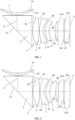
- FIG. 1 to FIG. 3 are schematic diagrams of hardware structures of optical lenses according to embodiments of this application.
- the optical lens includes: a first lens 1, a reflector 2, a diaphragm 3, a second lens 4, a third lens 5, a fourth lens 6, and a fifth lens 7 in sequence from an object side to an image side.
- the first lens 1 has positive refractive power.
- a surface S1, facing the object side, of the first lens 1 is a concave surface close to an optical axis 8.
- a surface S2, facing the image side, of the first lens 1 is a convex surface close to the optical axis 8.
- the surface S1, facing the object side, of the first lens 1 is the concave surface that is bent in a direction away from the object side and that is close to the optical axis 8
- the surface S2, facing the object side, of the first lens 1 is the convex surface that is bent in a direction close to the image side and that is close to the optical axis 8.
- the second lens 4 has positive refractive power.
- a surface S3, facing the object side, of the second lens 4 is a convex surface close to the optical axis 8.
- the surface S3, facing the object side, of the second lens 4 is the convex surface that is bent in a direction close to the object side and that is close to the optical axis 8
- a surface S4, facing the image side, of the second lens 4 may be a convex surface that is bent in a direction close to the image side and that is close to the optical axis 8, or may be a concave surface that is bent in a direction away from the image side, which is specifically related to refractive power of the fourth lens 6 and the fifth lens 7.
- the reflector 2 is configured to reflect incident light transmitted by the first lens 1, to enable reflected incident light to be transmitted to the second lens 4.
- the reflector 2 is a triangular prism.
- a cross section of the triangular prism is a right-angle triangle. Specifically, one right angle surface of the triangular prism faces the first lens 1, and the other right angle surface of the triangular prism faces the second lens 4.
- a reflection surface 21 of the reflector 2 namely, an oblique surface of the triangular prism, is used to reflect incident light transmitted by the first lens 1, to enable reflected incident light to be transmitted to the second lens 4.
- the reflector 2 can enable the light transmitted from the first lens 1 to be reflected, and then transmit reflected light to the second lens 4. Therefore, installation space occupied by the optical lens can be effectively reduced while an optical path direction can be changed.
- the diaphragm 3 is disposed on an edge of the surface S3, facing the object side, of the second lens 4.
- the third lens 5 has negative refractive power.
- a surface S5, facing the object side, of the third lens 5 is a convex surface close to the optical axis 8.
- a surface S6, facing the image side, of the third lens 5 is a concave surface close to the optical axis 8.
- the surface S5, facing the object side, of the third lens 5 is the convex surface that is bent in a direction close to the object side and that is close to the optical axis 8
- the surface S6, facing the image side, of the third lens 5 is the concave surface that is bent in the direction away from the image side and that is close to the optical axis 8.
- the fourth lens 6 has refractive power.
- a surface S7, facing the object side, of the fourth lens 6 is a convex surface close to the optical axis 8.
- a surface S8, facing the image side, of the fourth lens 6 is a concave surface close to the optical axis 8.
- the surface S7, facing the object side, of the fourth lens 6 is the convex surface that is bent in the direction close to the object side and that is close to the optical axis 8
- the surface S8, facing the image side, of the fourth lens 6 is the concave surface that is bent in the direction away from the image side and that is close to the optical axis 8.
- the fifth lens 7 has refractive power.
- the surface, facing the object side, of the lens may be referred to as an object side surface
- the surface, facing the image side, of the lens may be referred to as an image side surface
- the object side surface of the lens specifically means a surface away from a photosensitive element
- the image side surface of the lens specifically means a surface close to the photosensitive element.
- refractive power of a lens means a focusing capability or a diffusion capability of the lens on light.
- a lens having positive refractive power indicates that the lens can focus incident beams.
- a lens having negative refractive power indicates that the lens can expand a width of incident light.
- the optical lens satisfies the following relational expression:
- the surface S4, facing the image side, of the second lens 4 is the convex surface close to the optical axis 8.
- the refractive power of the fourth lens 6 is negative refractive power.
- the refractive power of the fifth lens 7 is positive refractive power.
- a surface S9, facing the object side, of the fifth lens 7 is a convex surface close to the optical axis 8.
- a surface S10, facing the image side, of the fifth lens 7 is a concave surface close to the optical axis 8.
- the surface S9, facing the object side, of the fifth lens 7 is the convex surface that is bent in the direction close to the object side and that is close to the optical axis 8
- the surface S10, facing the image side, of the fifth lens 7 is the concave surface that is bent in the direction away from the image side and that is close to the optical axis 8.
- the surface S4, facing the image side, of the second lens 4 is the concave surface close to the optical axis 8.
- the refractive power of the fourth lens 6 is positive refractive power.
- the refractive power of the fifth lens 7 is negative refractive power.
- a surface S9, facing the object side, of the fifth lens 7 is a convex surface close to the optical axis 8.
- a surface S10, facing the image side, of the fifth lens 7 is a convex surface close to the optical axis 8.
- the surface S9, facing the object side, of the fifth lens 7 is the convex surface that is bent in the direction close to the object side and that is close to the optical axis 8
- the surface S10, facing the image side, of the fifth lens 7 is the convex surface that is bent in the direction close to the image side and that is close to the optical axis 8.
- an angle between the reflection surface 21 of the reflector 2 and the optical axis 8 corresponding to the first lens 1 is 45 degrees.
- the reflection surface 21 of the reflector 2 can enable light transmitted from the first lens 1 to be reflected at 90 degrees and then transmit reflected light to the second lens 4. Therefore, installation space occupied by the optical lens can be effectively reduced while an optical path direction can be changed.
- a focal length of the first lens 1 satisfies the following relational expression: 0 ⁇ EFL1 ⁇ 50 mm , where EFL1 represents the focal length of the first lens . where EFL1 represents the focal length of the first lens.
- the focal length of the first lens 1 is controlled to be a relatively small positive value, so that the first lens having a relatively large focal power can be obtained. In this way, a light height can be reduced effectively by using the first lens 1, and a light intake can be increased while miniaturization of the optical lens is satisfied.
- the optical lens satisfies the following relational expression: DL/EFL ⁇ 0.55, where DL represents a length that is in an optical axis direction and that is between the surface S3 facing the object side, of the second lens 4 and the surface S10, facing the image side, of the fifth lens 7, and EFL represents an effective focal length of the optical lens.
- the first lens 1, the second lens 4, the third lens 5, the fourth lens 6, and the fifth lens 7 are all aspherical lenses.
- a refractive index, an Abbe number, and a focal length of the optical lens are all with reference to light having a wavelength of 555.00 nm.
- Table 1 shows lens data of the optical lens.
- Table 2 shows high-order coefficients A4, A6, A8, A10, A12, A14, A16, A18, and A20 of aspherical surfaces of the optical lens.
- TTL is a distance, on the optical axis, from an object side surface of the first lens 1 to an imaging surface of the photosensitive element.
- Imgh is half a diagonal length of an effective pixel area of the optical lens.
- parameters in three rows between a row in which S2 is located and a row in which Stop is located in the table correspondingly represent parameters of the reflector.
- 3.550 represents a vertical distance from a point in an oblique surface of the reflector to a surface, facing the first lens 1, of the reflector; and -3.550 represents a vertical distance from a point in the oblique surface of the reflector to a surface, facing the second lens 4, of the reflector.
- 0.571 represents a gap distance between a surface, facing the second lens 4, of the reflector and the diaphragm STO.
- S1 represents the object side surface (a surface facing the object side) of the first lens 1;
- S2 represents an image side surface (a surface facing the image side) of the first lens 1;
- S3 represents an object side surface of the second lens 4, and
- S4 represents an image side surface of the second lens 4;
- S5 represents an object side surface of the third lens 5, and
- S6 represents an image side surface of the third lens 5;
- S7 represents an object side surface of the fourth lens 6, and S8 represents an image side surface of the fourth lens 6;
- S9 represents an object side surface of the fifth lens 7, and S10 represents an image side surface of the fifth lens 7.
- S11 and S12 represent two opposite surfaces of an optical filter in the optical module including the optical lens.
- S13 represents an imaging surface of a photosensitive element in the optical module including the optical lens.
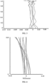
- An optical lens that has a size range in the foregoing example is corresponding to the following: a schematic diagram (in this diagram, a horizontal coordinate represents a vertical axis chromatic aberration size in unit of microns; and a vertical coordinate represents an actual image height, in unit of millimeters) of a vertical axis chromatic aberration curve shown in FIG. 4 , a schematic diagram (in this diagram, a horizontal coordinate represents an axial chromatic aberration size in unit of millimeters; and a vertical coordinate represents a normalized entrance pupil radius, without unit) of an axial chromatic aberration curve shown in FIG.
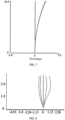
- FIG. 5 a schematic diagram (in the diagram, a horizontal coordinate represents an astigmatic size in unit of millimeters; and a vertical coordinate represents a field number, without unit) of an astigmatic curve shown in FIG. 6
- a schematic diagram in the diagram, a horizontal coordinate represents a distortion size without unit, and is represented by a percentage; and a vertical coordinate represents a field number, without unit) of a distortion curve shown in FIG. 7 .
- the vertical axis chromatic aberration curve represents a deviation between different image heights of light on an imaging surface after passing through an optical lens.
- the axial chromatic aberration curve represents a deviation that is from a focus at which light of different wavelengths converges after passing through the optical lens.
- the astigmatic curve represents that a meridian image surface is bent and a sagittal image surface is bent.
- the distortion curve represents distortion values corresponding to different fields of view.
- a refractive index, an Abbe number, and a focal length of the optical lens are all with reference to light having a wavelength of 555.00 nm.
- Table 3 shows lens data of the optical lens.
- Table 4 shows high-order coefficients A4, A6, A8, A10, A12, A14, A16, A18, and A20 of aspherical surfaces of the optical lens.
- parameters in three rows between a row in which S2 is located and a row in which Stop is located in the table correspondingly represent parameters of the reflector.
- 3.650 represents a vertical distance from a point in an oblique surface of the reflector to a surface, facing the first lens 1, of the reflector; and -3.650 represents a vertical distance from a point in the oblique surface of the reflector to a surface, facing the second lens 4, of the reflector.
- 0.803 represents a gap distance between a surface, facing the second lens 4, of the reflector and the diaphragm STO.
- An optical lens that has a size range in the foregoing example is corresponding to the following: a schematic diagram (in this diagram, a horizontal coordinate represents a vertical axis chromatic aberration size in unit of microns; and a vertical coordinate represents an actual image height, in unit of millimeters) of a vertical axis chromatic aberration curve shown in FIG. 8 , a schematic diagram (in this diagram, a horizontal coordinate represents an axial chromatic aberration size in unit of millimeters; and a vertical coordinate represents a normalized entrance pupil radius, without unit) of an axial chromatic aberration curve shown in FIG.
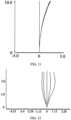
- a schematic diagram in the diagram, a horizontal coordinate represents an astigmatic size in unit of millimeters; and a vertical coordinate represents a field number, without unit) of an astigmatic curve shown in FIG. 10
- a schematic diagram in the diagram, a horizontal coordinate represents a distortion size without unit, and is represented by a percentage; and a vertical coordinate represents a field number, without unit) of a distortion curve shown in FIG. 11 .
- the structure of the optical lens and a refractive index, an Abbe number, and a focal length of the optical lens are all with reference to light having a wavelength of 555.00 nm.
- Table 5 shows lens data of the optical lens.
- Table 6 shows high-order coefficients A4, A6, A8, A10, A12, A14, A16, A18, and A20 of aspherical surfaces of the optical lens.
- parameters in three rows between a row in which S2 is located and a row in which Stop is located in the table correspondingly represent parameters of the reflector.
- 3.700 represents a vertical distance from a point in an oblique surface of the reflector to a surface, facing the first lens 1, of the reflector; and -3.700 represents a vertical distance from a point in the oblique surface of the reflector to a surface, facing the second lens 4, of the reflector.
- 0.597 represents a gap distance between a surface, facing the second lens 4, of the reflector and the diaphragm STO.
- An optical lens that has a size range in the foregoing example is corresponding to the following: a schematic diagram (in this diagram, a horizontal coordinate represents a vertical axis chromatic aberration size in unit of microns; and a vertical coordinate represents an actual image height, in unit of millimeters) of a vertical axis chromatic aberration curve shown in FIG. 12 , a schematic diagram (in this diagram, a horizontal coordinate represents an axial chromatic aberration size in unit of millimeters; and a vertical coordinate represents a normalized entrance pupil radius, without unit) of an axial chromatic aberration curve shown in FIG.
- FIG. 13 a schematic diagram (in the diagram, a horizontal coordinate represents an astigmatic size in unit of millimeters; and a vertical coordinate represents a field number, without unit) of an astigmatic curve shown in FIG. 14 , and a schematic diagram (in the diagram, a horizontal coordinate represents a distortion size without unit, and is represented by a percentage; and a vertical coordinate represents a field number, without unit) of a distortion curve shown in FIG. 15 .
- Focal power, materials, surface types, and central thicknesses of lenses, axial spacings between lenses, and the like are properly allocated, to enable the imaging lens to have at least one type of beneficial effect such as a long focal length, a large aperture, high imaging quality, and easy processing.
- a value range of an equivalent focal length of the optical lens in embodiments of this application is 125 mm-250 mm. To be specific, the value range is equivalent to five times a focal length section to ten times the focal length section.
- the optical lens includes: the first lens, the reflector, the diaphragm, the second lens, the third lens, the fourth lens, and the fifth lens in sequence from the object side to the image side.
- the first lens has the positive refractive power.
- the surface, facing the object side, of the first lens is the concave surface close to the optical axis.
- the surface, facing the image side, of the first lens is the convex surface close to the optical axis.
- the second lens has the positive refractive power.
- the surface, facing the object side, of the second lens is the convex surface close to the optical axis.
- the reflector is configured to reflect the incident light transmitted by the first lens, to enable reflected incident light to be transmitted to the second lens.
- the third lens has the negative refractive power.
- the surface, facing the object side, of the third lens is the convex surface close to the optical axis.
- the surface, facing the image side, of the third lens is the concave surface close to the optical axis.
- the fourth lens has the refractive power.
- the surface, facing the object side, of the fourth lens is the convex surface close to the optical axis.
- the surface, facing the image side, of the fourth lens is the concave surface close to the optical axis.
- the fifth lens has the refractive power.
- An embodiment of this application further provides an optical module, including the optical lens described in the foregoing embodiments.
- the optical module in this embodiment of this application further includes:
- Two opposite surfaces of the optical filter 10 are respectively represented as S11 and S12.
- An imaging surface of the photosensitive element 9 is represented as S13.
- the optical filter 10 is an infrared optical filter.
- An embodiment of this application further provides an electronic device, including the optical module as described above.
Landscapes
- Physics & Mathematics (AREA)
- General Physics & Mathematics (AREA)
- Optics & Photonics (AREA)
- Lenses (AREA)
Abstract
Description
- This application claims priority to
Chinese Patent Application No. 202110925916.8, filed on August 12, 2021 - This application relates to the technical field of communication devices, and in particular, to an optical lens, an optical module, and an electronic device.
- At present, with the continuous development of mobile communication technologies, smart electronic devices such as mobile phones, unmanned aerial vehicles, and tablet computers are developing toward miniaturization and ultra thinness. This enables an overall volume of an optical lens to be continuously compressed. However, if a higher-quality photographing function is to be implemented, excessively compressing a lens volume may reduce image quality of imaging. Therefore, a periscope camera lens emerges, to prevent compression of the lens volume and possibly implement high-definition image photographing effect while ultra-thinness and miniaturization of a terminal product are not changed. Currently, a wide variety of periscope lenses dominate photographing of high-end mobile phones by virtue of length and zooming advantages of the periscope lenses, and are favored by consumers.
- Due to a limitation of a thickness of an overall smart electronic device provided with a periscope lens, a caliber of the periscope camera cannot be large, and a light transmission amount is small, causing a problem of poor imaging quality in a dark light condition.
- Embodiments of this application provide an optical lens, an optical module, and an electronic device, to resolve a problem of poor imaging quality of an existing smart electronic device in a dark light condition.
- To resolve the technical problem, this application is implemented as follows.
- According to a first aspect, an embodiment of this application provides an optical lens, in sequence from an object side to an image side, including:
a first lens, a reflector, a diaphragm, a second lens, a third lens, a fourth lens, and a fifth lens. - The first lens has positive refractive power. A surface, facing the object side, of the first lens is a concave surface close to an optical axis, and a surface, facing the image side, of the first lens is a convex surface close to the optical axis.
- The second lens has positive refractive power. A surface, facing the object side, of the second lens is a convex surface close to the optical axis.
- The reflector is configured to reflect incident light transmitted by the first lens, to enable reflected incident light to be transmitted to the second lens.
- The third lens has negative refractive power. A surface, facing the object side, of the third lens is a convex surface close to the optical axis, and a surface, facing the image side, of the third lens is a concave surface close to the optical axis.
- The fourth lens has refractive power. A surface, facing the object side, of the fourth lens is a convex surface close to the optical axis, and a surface, facing the image side, of the fourth lens is a concave surface close to the optical axis.
- The fifth lens has refractive power.
- According to a second aspect, an embodiment of this application further provides an optical module, including the optical lens described in the embodiment in the first aspect.
- According to a third aspect, an embodiment of this application further provides an electronic device, including the optical module described in the embodiment in the second aspect.
- In embodiments of this application, the optical lens includes: the first lens, the reflector, the diaphragm, the second lens, the third lens, the fourth lens, and the fifth lens in sequence from the object side to the image side. The first lens has the positive refractive power. The surface, facing the object side, of the first lens is the concave surface close to the optical axis. The surface, facing the image side, of the first lens is the convex surface close to the optical axis. The second lens has the positive refractive power. The surface, facing the object side, of the second lens is the convex surface close to the optical axis. The reflector is configured to reflect the incident light transmitted by the first lens, to enable reflected incident light to be transmitted to the second lens. The third lens has the negative refractive power. The surface, facing the object side, of the third lens is the convex surface close to the optical axis. The surface, facing the image side, of the third lens is the concave surface close to the optical axis. The fourth lens has the refractive power. The surface, facing the object side, of the fourth lens is the convex surface close to the optical axis, and the surface, facing the image side, of the fourth lens is the concave surface close to the optical axis. The fifth lens has the refractive power. In this way, the optical lens provided with the foregoing structure can increase the light intake while increasing the focal length of the optical lens. When the optical lens is used in an electronic device, remote photographing and imaging requirements in a dark light condition can be satisfied.
-
-
FIG. 1 is a first schematic diagram of a hardware structure of an optical lens according to an embodiment of this application; -
FIG. 2 is a second schematic diagram of a hardware structure of an optical lens according to an embodiment of this application; -
FIG. 3 is a third schematic diagram of a hardware structure of an optical lens according to an embodiment of this application; -
FIG. 4 is a first schematic diagram of a vertical axis chromatic aberration curve corresponding to the optical lens shown inFIG. 1 ; -
FIG. 5 is a first schematic diagram of an axial chromatic aberration curve corresponding to the optical lens shown inFIG. 1 ; -
FIG. 6 is a first schematic diagram of an astigmatic curve corresponding to the optical lens shown inFIG. 1 ; -
FIG. 7 is a first schematic diagram of a distortion curve corresponding to the optical lens shown inFIG. 1 ; -
FIG. 8 is a second schematic diagram of a vertical axis chromatic aberration curve corresponding to the optical lens shown inFIG. 2 ; -
FIG. 9 is a second schematic diagram of an axial chromatic aberration curve corresponding to the optical lens shown inFIG. 2 ; -
FIG. 10 is a second schematic diagram of an astigmatic curve corresponding to the optical lens shown inFIG. 2 ; -
FIG. 11 is a second schematic diagram of a distortion curve corresponding to the optical lens shown inFIG. 2 ; -
FIG. 12 is a third schematic diagram of a vertical axis chromatic aberration curve corresponding to the optical lens shown inFIG. 3 ; -
FIG. 13 is a third schematic diagram of an axial chromatic aberration curve corresponding to the optical lens shown inFIG. 3 ; -
FIG. 14 is a third schematic diagram of an astigmatic curve corresponding to the optical lens shown inFIG. 3 ; and -
FIG. 15 is a third schematic diagram of a distortion curve corresponding to the optical lens shown inFIG. 3 . - The following clearly and completely describes technical solutions in embodiments of this application with reference to accompanying drawings in embodiments of this application. Apparently, the described embodiments are some but not all of embodiments of this application. All other embodiments obtained by a person of ordinary skill in the art based on embodiments of this application without creative efforts shall fall within the protection scope of this application.
- The terms "first", "second", and the like in this specification and claims of this application are used to distinguish between similar objects instead of describing a specific order or sequence. It should be understood that data used in such a way are interchangeable in proper circumstances, so that embodiments of this application can be implemented in an order other than the order illustrated or described herein. Objects classified by "first", "second", and the like are usually of a same type, and the number of objects is not limited. For example, there may be one or more first objects. In addition, in this specification and the claims, "and/or" represents at least one of connected objects, and a character "/" generally represents an "or" relationship between associated objects.
- With reference to the accompanying drawings, the following describes in detail an optical lens in embodiments of this application based on specific embodiments and application scenarios thereof.
-
FIG. 1 to FIG. 3 are schematic diagrams of hardware structures of optical lenses according to embodiments of this application. The optical lens includes: afirst lens 1, areflector 2, adiaphragm 3, asecond lens 4, athird lens 5, afourth lens 6, and afifth lens 7 in sequence from an object side to an image side. - The
first lens 1 has positive refractive power. A surface S1, facing the object side, of thefirst lens 1 is a concave surface close to anoptical axis 8. A surface S2, facing the image side, of thefirst lens 1 is a convex surface close to theoptical axis 8. - It should be noted that the surface S1, facing the object side, of the
first lens 1 is the concave surface that is bent in a direction away from the object side and that is close to theoptical axis 8, and the surface S2, facing the object side, of thefirst lens 1 is the convex surface that is bent in a direction close to the image side and that is close to theoptical axis 8. - The
second lens 4 has positive refractive power. A surface S3, facing the object side, of thesecond lens 4 is a convex surface close to theoptical axis 8. - It should be noted that, the surface S3, facing the object side, of the
second lens 4 is the convex surface that is bent in a direction close to the object side and that is close to theoptical axis 8, and a surface S4, facing the image side, of thesecond lens 4 may be a convex surface that is bent in a direction close to the image side and that is close to theoptical axis 8, or may be a concave surface that is bent in a direction away from the image side, which is specifically related to refractive power of thefourth lens 6 and thefifth lens 7. - The
reflector 2 is configured to reflect incident light transmitted by thefirst lens 1, to enable reflected incident light to be transmitted to thesecond lens 4. - Optionally, the
reflector 2 is a triangular prism. A cross section of the triangular prism is a right-angle triangle. Specifically, one right angle surface of the triangular prism faces thefirst lens 1, and the other right angle surface of the triangular prism faces thesecond lens 4. Areflection surface 21 of thereflector 2, namely, an oblique surface of the triangular prism, is used to reflect incident light transmitted by thefirst lens 1, to enable reflected incident light to be transmitted to thesecond lens 4. In other words, thereflector 2 can enable the light transmitted from thefirst lens 1 to be reflected, and then transmit reflected light to thesecond lens 4. Therefore, installation space occupied by the optical lens can be effectively reduced while an optical path direction can be changed. - Optionally, the
diaphragm 3 is disposed on an edge of the surface S3, facing the object side, of thesecond lens 4. - The
third lens 5 has negative refractive power. A surface S5, facing the object side, of thethird lens 5 is a convex surface close to theoptical axis 8. A surface S6, facing the image side, of thethird lens 5 is a concave surface close to theoptical axis 8. - It should be noted that, the surface S5, facing the object side, of the
third lens 5 is the convex surface that is bent in a direction close to the object side and that is close to theoptical axis 8, and the surface S6, facing the image side, of thethird lens 5 is the concave surface that is bent in the direction away from the image side and that is close to theoptical axis 8. - The
fourth lens 6 has refractive power. A surface S7, facing the object side, of thefourth lens 6 is a convex surface close to theoptical axis 8. A surface S8, facing the image side, of thefourth lens 6 is a concave surface close to theoptical axis 8. - It should be noted that the surface S7, facing the object side, of the
fourth lens 6 is the convex surface that is bent in the direction close to the object side and that is close to theoptical axis 8, and the surface S8, facing the image side, of thefourth lens 6 is the concave surface that is bent in the direction away from the image side and that is close to theoptical axis 8. - The
fifth lens 7 has refractive power. - Herein, the surface, facing the object side, of the lens may be referred to as an object side surface, and the surface, facing the image side, of the lens may be referred to as an image side surface. Specifically, the object side surface of the lens specifically means a surface away from a photosensitive element, and the image side surface of the lens specifically means a surface close to the photosensitive element.
- Herein, refractive power of a lens means a focusing capability or a diffusion capability of the lens on light. Specifically, a lens having positive refractive power indicates that the lens can focus incident beams. A lens having negative refractive power indicates that the lens can expand a width of incident light.
- Optionally, the optical lens satisfies the following relational expression:
- 10°<HFOV<20°, where HFOV represents a horizontal field of view angle of the optical lens; and
- 1.8<F/NO<2.5, where F/NO represents a quantity of apertures of the optical lens.
- As shown in
FIG. 1 and FIG. 2 , in an optional first implementation, the surface S4, facing the image side, of thesecond lens 4 is the convex surface close to theoptical axis 8. The refractive power of thefourth lens 6 is negative refractive power. - The refractive power of the
fifth lens 7 is positive refractive power. A surface S9, facing the object side, of thefifth lens 7 is a convex surface close to theoptical axis 8. A surface S10, facing the image side, of thefifth lens 7 is a concave surface close to theoptical axis 8. - It should be noted that the surface S9, facing the object side, of the
fifth lens 7 is the convex surface that is bent in the direction close to the object side and that is close to theoptical axis 8, and the surface S10, facing the image side, of thefifth lens 7 is the concave surface that is bent in the direction away from the image side and that is close to theoptical axis 8. - As shown in
FIG. 3 , in an optional second implementation, the surface S4, facing the image side, of thesecond lens 4 is the concave surface close to theoptical axis 8. The refractive power of thefourth lens 6 is positive refractive power. - The refractive power of the
fifth lens 7 is negative refractive power. A surface S9, facing the object side, of thefifth lens 7 is a convex surface close to theoptical axis 8. A surface S10, facing the image side, of thefifth lens 7 is a convex surface close to theoptical axis 8. - It should be noted that the surface S9, facing the object side, of the
fifth lens 7 is the convex surface that is bent in the direction close to the object side and that is close to theoptical axis 8, and the surface S10, facing the image side, of thefifth lens 7 is the convex surface that is bent in the direction close to the image side and that is close to theoptical axis 8. - Optionally, an angle between the
reflection surface 21 of thereflector 2 and theoptical axis 8 corresponding to thefirst lens 1 is 45 degrees. - To be specific, the
reflection surface 21 of thereflector 2 can enable light transmitted from thefirst lens 1 to be reflected at 90 degrees and then transmit reflected light to thesecond lens 4. Therefore, installation space occupied by the optical lens can be effectively reduced while an optical path direction can be changed. - In an optional implementation, a focal length of the
first lens 1 satisfies the following relational expression:
- It should be noted that the focal length of the
first lens 1 is controlled to be a relatively small positive value, so that the first lens having a relatively large focal power can be obtained. In this way, a light height can be reduced effectively by using thefirst lens 1, and a light intake can be increased while miniaturization of the optical lens is satisfied. - In an optional implementation, the optical lens satisfies the following relational expression:
DL/EFL≤0.55, where DL represents a length that is in an optical axis direction and that is between the surface S3 facing the object side, of thesecond lens 4 and the surface S10, facing the image side, of thefifth lens 7, and EFL represents an effective focal length of the optical lens. - Optionally, the
first lens 1, thesecond lens 4, thethird lens 5, thefourth lens 6, and thefifth lens 7 are all aspherical lenses. - It should be noted that an aspherical surface formula used in the optical lens in embodiments of this application is defined as follows:

- The following specifically describes, in three embodiments, parameters for specific implementation of the optical lens in embodiments of this application.
- Refer to the structure of the optical lens in
FIG. 1 . A refractive index, an Abbe number, and a focal length of the optical lens are all with reference to light having a wavelength of 555.00 nm. Table 1 shows lens data of the optical lens. Table 2 shows high-order coefficients A4, A6, A8, A10, A12, A14, A16, A18, and A20 of aspherical surfaces of the optical lens.Table 1 Embodiment 1EFL=14.5 mm, F/NO=1.9, FOV=20°, TTL=21.5, Imgh=2.5, MIC=5.3 Surface No. Surface type Radius of curvature (mm) Thickness (mm) Refractive index Abbe number Conic coefficient 0 Spherical surface Unlimited Unlimited Unlimited S1 Aspheric surface -13.675 0.528 1.544 56.114 2.54 S2 Aspheric surface -9.126 0.015 1.78 3.550 1.61 38.08 Unlimited -3.550 1.61 38.08 Unlimited 0.571 Unlimited Stop Spherical surface Unlimited -0.561 Unlimited S3 Aspheric surface 6.223 1.799 1.544 56.114 -2.86 S4 Aspheric surface -26.640 0.104 46.14 S5 Aspheric surface 6.474 0.990 1.661 20.37 -4.91 S6 Aspheric surface 3.337 0.650 -0.46 S7 Aspheric surface 6.006 1.000 1.639 23.53 3.22 S8 Aspheric surface 3.203 1.422 0.73 S9 Aspheric surface 4.035 0.696 1.639 23.53 0 S10 Aspheric surface 8.505 2.450 -45.70 S11 Spherical surface Unlimited 0.150 1.517 64.167 Unlimited S12 Spherical surface Unlimited 4.319 Unlimited S13 Spherical surface Unlimited 0.00 Unlimited - In the table, TTL is a distance, on the optical axis, from an object side surface of the
first lens 1 to an imaging surface of the photosensitive element. Imgh is half a diagonal length of an effective pixel area of the optical lens. - It should be noted that parameters in three rows between a row in which S2 is located and a row in which Stop is located in the table correspondingly represent parameters of the reflector.
- Specifically, 3.550 represents a vertical distance from a point in an oblique surface of the reflector to a surface, facing the
first lens 1, of the reflector; and -3.550 represents a vertical distance from a point in the oblique surface of the reflector to a surface, facing thesecond lens 4, of the reflector. 0.571 represents a gap distance between a surface, facing thesecond lens 4, of the reflector and the diaphragm STO. - In the table, S1 represents the object side surface (a surface facing the object side) of the
first lens 1; S2 represents an image side surface (a surface facing the image side) of thefirst lens 1; S3 represents an object side surface of thesecond lens 4, and S4 represents an image side surface of thesecond lens 4; S5 represents an object side surface of thethird lens 5, and S6 represents an image side surface of thethird lens 5; S7 represents an object side surface of thefourth lens 6, and S8 represents an image side surface of thefourth lens 6; and S9 represents an object side surface of thefifth lens 7, and S10 represents an image side surface of thefifth lens 7. - S11 and S12 represent two opposite surfaces of an optical filter in the optical module including the optical lens. S13 represents an imaging surface of a photosensitive element in the optical module including the optical lens.
Table 2 Surface No. A4 A6 A8 A10 A12 A14 A16 A18 A20 SI -1.264E-03 3.196E-05 4.500E-06 -6.203E-08 0.000E+00 0.000E+00 0.000E+00 0.000E+00 0.000E+00 S2 -8.916E-04 5.810E-05 2.784E-06 0.000E+00 0.000E+00 0.000E+00 0.000E+00 0.000E+00 0.000E+00 S3 -8.674E-04 -4.496E-04 6.155E-04 -2.632E-04 6.401E-05 -9.685E-06 9.250E-07 -5.407E-08 1.752E-09 S4 -2.796E-02 3.173E-02 -1.943E-02 7.497E-03 -1.947E-03 3.538E-04 -4.579E-05 4.219E-06 -2.712E-07 S5 -1.404E-02 1.996E-02 -7.966E-03 -1.356E-03 2.417E-03 -1.055E-03 2.638E-04 -4.309E-05 4.774E-06 S6 1.901E-02 -1.354E-02 2.216E-02 -2.723E-02 1.849E-02 -7.663E-03 2.070E-03 -3.746E-04 4.528E-05 S7 5.230E-03 -6.188E-03 1.058E-02 -1.138E-02 7.355E-03 -2.944E-03 7.687E-04 -1.357E-04 1.665E-05 S8 -2.426E-02 3.048E-03 8.650E-04 -5.351E-04 -4.962E-04 8.608E-04 -4.898E-04 1.266E-04 -6.396E-06 S9 -1.403E-02 -1.818E-05 -5.870E-04 4.245E-04 -1.378E-04 2.502E-05 -2.536E-06 1.608E-07 -7.855E-09 S10 3.663E-03 -4.061E-03 5.890E-04 2.176E-04 -1.588E-04 4.635E-05 -7.500E-06 6.703E-07 -2.582E-08 - An optical lens that has a size range in the foregoing example is corresponding to the following: a schematic diagram (in this diagram, a horizontal coordinate represents a vertical axis chromatic aberration size in unit of microns; and a vertical coordinate represents an actual image height, in unit of millimeters) of a vertical axis chromatic aberration curve shown in
FIG. 4 , a schematic diagram (in this diagram, a horizontal coordinate represents an axial chromatic aberration size in unit of millimeters; and a vertical coordinate represents a normalized entrance pupil radius, without unit) of an axial chromatic aberration curve shown inFIG. 5 , a schematic diagram (in the diagram, a horizontal coordinate represents an astigmatic size in unit of millimeters; and a vertical coordinate represents a field number, without unit) of an astigmatic curve shown inFIG. 6 , and a schematic diagram (in the diagram, a horizontal coordinate represents a distortion size without unit, and is represented by a percentage; and a vertical coordinate represents a field number, without unit) of a distortion curve shown inFIG. 7 . - The vertical axis chromatic aberration curve represents a deviation between different image heights of light on an imaging surface after passing through an optical lens. The axial chromatic aberration curve represents a deviation that is from a focus at which light of different wavelengths converges after passing through the optical lens. The astigmatic curve represents that a meridian image surface is bent and a sagittal image surface is bent. The distortion curve represents distortion values corresponding to different fields of view.
- Refer to the structure of the optical lens in
FIG. 1 . A refractive index, an Abbe number, and a focal length of the optical lens are all with reference to light having a wavelength of 555.00 nm. Table 3 shows lens data of the optical lens. Table 4 shows high-order coefficients A4, A6, A8, A10, A12, A14, A16, A18, and A20 of aspherical surfaces of the optical lens.Table 3 Embodiment 2EFL=18.9 mm, F/NO=2.4, Fov=10.5°, TTL=23.5, Imgh=2.5, MIC=5.3 Surface No. Surface type Radius of curvature (mm) Thickness (mm) Refractive index Abbe number Conic coefficient 0 Spherical surface Unlimited Unlimited Unlimited S1 Aspheric surface -11.184 0.624 1.544 56.114 2.51 S2 Aspheric surface -7.333 0.015 0.93 3.650 1.61 38.08 -3.650 1.61 38.08 0.803 Stop Spherical surface Unlimited -0.793 Unlimited S3 Aspheric surface 4.710 1.800 1.544 56.114 -2.00 S4 Aspheric surface 96.392 0.010 -99.00 S5 Aspheric surface 7.280 1.000 1.661 20.37 -6.03 S6 Aspheric surface 2.618 0.650 -0.57 S7 Aspheric surface 4.502 1.000 1.639 23.53 2.08 S8 Aspheric surface 7.711 1.700 3.16 S9 Aspheric surface -7.216 1.800 1.639 23.53 0 S10 Aspheric surface -8.391 1.555 -32.75 S11 Spherical surface Unlimited 0.150 1.517 64.167 Unlimited S12 Spherical surface Unlimited 3.424 Unlimited S13 Spherical surface Unlimited 0.00 Unlimited - For meanings represented by identifier symbols in Table 3, refer to some descriptions in Table 1. The details are not described herein again.
- It should be noted that parameters in three rows between a row in which S2 is located and a row in which Stop is located in the table correspondingly represent parameters of the reflector.
- Specifically, 3.650 represents a vertical distance from a point in an oblique surface of the reflector to a surface, facing the
first lens 1, of the reflector; and -3.650 represents a vertical distance from a point in the oblique surface of the reflector to a surface, facing thesecond lens 4, of the reflector. 0.803 represents a gap distance between a surface, facing thesecond lens 4, of the reflector and the diaphragm STO.Table 4 Surface No. A4 A6 A8 A10 A12 A14 A16 A18 A20 S1 -1.777E-03 1.705E-05 6.513E-06 -1.007E-07 0.000E+00 0.000E+00 0.000E+00 0.000E+00 0.000E+00 S2 -1.281E-03 5.763E-05 3.364E-06 0.000E+00 0.000E+00 0.000E+00 0.000E+00 0.000E+00 0.000E+00 S3 -2.232E-01 -2.569E-02 -3.136E-02 5.533E-03 2.317E-03 1.106E-03 1.993E-04 -6.143E-04 4.967E-04 S4 -2.796E-02 3.173E-02 -1.943E-02 7.497E-03 -1.947E-03 3.538E-04 -4.579E-05 4.219E-06 -2.712E-07 S5 -1.392E-01 -6.454E-02 3.319E-02 -8.126E-04 5.085E-03 -4.116E-04 1.861E-04 -6.111E-04 3.050E-04 S6 -3.410E-02 -1.078E-01 2.775E-02 -7.470E-03 3.752E-03 -6.480E-05 -2.901E-04 -6.743E-05 -8.143E-05 S7 -1.259E-02 -3.771E-02 -3.231E-03 -1.220E-02 -2.524E-03 -2.282E-03 -1.569E-03 -9.179E-04 -5.118E-04 S8 -1.928E-01 3.895E-02 2.740E-04 -6.110E-03 -1.978E-03 -1.224E-03 -5.737E-04 -2.148E-04 -5.516E-05 S9 -3.861E-01 -4.383E-03 1.485E-03 -2.161E-04 -4.775E-05 -8.416E-05 -3.302E-05 -4.697E-06 -3.150E-06 S10 -3.136E-01 2.249E-02 -8.279E-04 2.968E-04 4.430E-06 -2.097E-05 -9.926E-06 4.532E-06 1.832E-06 - An optical lens that has a size range in the foregoing example is corresponding to the following: a schematic diagram (in this diagram, a horizontal coordinate represents a vertical axis chromatic aberration size in unit of microns; and a vertical coordinate represents an actual image height, in unit of millimeters) of a vertical axis chromatic aberration curve shown in
FIG. 8 , a schematic diagram (in this diagram, a horizontal coordinate represents an axial chromatic aberration size in unit of millimeters; and a vertical coordinate represents a normalized entrance pupil radius, without unit) of an axial chromatic aberration curve shown inFIG. 9 , a schematic diagram (in the diagram, a horizontal coordinate represents an astigmatic size in unit of millimeters; and a vertical coordinate represents a field number, without unit) of an astigmatic curve shown inFIG. 10 , and a schematic diagram (in the diagram, a horizontal coordinate represents a distortion size without unit, and is represented by a percentage; and a vertical coordinate represents a field number, without unit) of a distortion curve shown inFIG. 11 . - Refer to the optical structure of
FIG. 3 . The structure of the optical lens and a refractive index, an Abbe number, and a focal length of the optical lens are all with reference to light having a wavelength of 555.00 nm. Table 5 shows lens data of the optical lens. Table 6 shows high-order coefficients A4, A6, A8, A10, A12, A14, A16, A18, and A20 of aspherical surfaces of the optical lens.Table 5 Embodiment 3EFL=14.5 mm, F/NO=1.9, FOV=20°, TTL=21.5, Imgh=2.5, MIC=5.3 Surface No. Surface type Radius of curvature (mm) Thickness (mm) Refractive index Abbe number Conic coefficient 0 Spherical surface Unlimited Unlimited Unlimited S1 Aspheric surface -11.296 0.617 1.544 56.114 2.41 S2 Aspheric surface -7.601 0.015 1.03 3.700 1.61 38.08 Unlimited -3.700 0.597 Unlimited Stop Spherical surface Unlimited -0.587 Unlimited S3 Aspheric surface 5.794 1.800 1.544 56.114 -3.75 S4 Aspheric surface -111.509 0.189 -91.00 S5 Aspheric surface 6.593 1.000 1.661 20.37 -4.18 S6 Aspheric surface 3.043 0.650 -0.42 S7 Aspheric surface 5.111 1.000 1.639 23.53 2.27 S8 Aspheric surface 3.409 1.700 0.82 S9 Aspheric surface 4.652 0.778 1.639 23.53 2 S10 Aspheric surface 11.619 2.222 9.34 S11 Spherical surface Unlimited 0.150 1.517 64.167 Unlimited S12 Spherical surface Unlimited 4.091 Unlimited S13 Spherical surface Unlimited 0.00 Unlimited - For meanings represented by identifier symbols in Table 5, refer to some descriptions in Table 1. The details are not described herein again.
- It should be noted that parameters in three rows between a row in which S2 is located and a row in which Stop is located in the table correspondingly represent parameters of the reflector.
- Specifically, 3.700 represents a vertical distance from a point in an oblique surface of the reflector to a surface, facing the
first lens 1, of the reflector; and -3.700 represents a vertical distance from a point in the oblique surface of the reflector to a surface, facing thesecond lens 4, of the reflector. 0.597 represents a gap distance between a surface, facing thesecond lens 4, of the reflector and the diaphragm STO.Table 6 Surface No. A4 A6 A8 A10 A12 A14 A16 A18 A20 S1 -1.498E-03 2.111E-05 5.706E-06 -8.728E-08 0.000E+00 0.000E+00 0.000E+00 0.000E+00 0.000E+00 S2 -1.144E-03 6.066E-05 3.014E-06 0.000E+00 0.000E+00 0.000E+00 0.000E+00 0.000E+00 0.000E+00 S3 -5.133E-02 1.406E-03 -2.436E-02 -4.544E-03 -5.011E-04 8.308E-04 5.084E-04 2.760E-04 2.153E-05 S4 -3.218E-01 2.836E-02 -3.450E-02 9.422E-03 -1.576E-03 2.997E-03 -1.178E-03 7.575E-04 -5.970E-04 S5 -1.235E-01 -4.720E-02 3.873E-02 7.804E-03 8.825E-04 -2.985E-04 -1.350E-03 5.501E-04 -3.807E-04 S6 -8.455E-03 -9.668E-02 9.670E-03 -4.779E-03 4.517E-03 2.189E-05 -5.101E-04 1.231E-04 -1.546E-04 S7 2.462E-02 2.232E-02 -1.870E-02 -9.444E-03 2.195E-03 -4.367E-04 -3.590E-04 -8.900E-05 -1.342E-04 S8 -3.110E-01 5.590E-02 -5.616E-03 -4.267E-03 -7.941E-04 -5.341E-04 -1.857E-04 -8.308E-05 -5.438E-05 S9 -5.314E-01 -1.221E-02 7.297E-04 -1.864E-03 -8.967E-04 -7.285E-04 -3.694E-04 -1.097E-04 -1.795E-05 S10 -5.313E-01 -2.713E-02 -1.578E-03 -3.633E-03 -1.409E-03 -7.947E-04 -1.936E-04 2.248E-05 1.984E-05 - An optical lens that has a size range in the foregoing example is corresponding to the following: a schematic diagram (in this diagram, a horizontal coordinate represents a vertical axis chromatic aberration size in unit of microns; and a vertical coordinate represents an actual image height, in unit of millimeters) of a vertical axis chromatic aberration curve shown in
FIG. 12 , a schematic diagram (in this diagram, a horizontal coordinate represents an axial chromatic aberration size in unit of millimeters; and a vertical coordinate represents a normalized entrance pupil radius, without unit) of an axial chromatic aberration curve shown inFIG. 13 , a schematic diagram (in the diagram, a horizontal coordinate represents an astigmatic size in unit of millimeters; and a vertical coordinate represents a field number, without unit) of an astigmatic curve shown inFIG. 14 , and a schematic diagram (in the diagram, a horizontal coordinate represents a distortion size without unit, and is represented by a percentage; and a vertical coordinate represents a field number, without unit) of a distortion curve shown inFIG. 15 . Focal power, materials, surface types, and central thicknesses of lenses, axial spacings between lenses, and the like are properly allocated, to enable the imaging lens to have at least one type of beneficial effect such as a long focal length, a large aperture, high imaging quality, and easy processing. - It should be noted that a value range of an equivalent focal length of the optical lens in embodiments of this application is 125 mm-250 mm. To be specific, the value range is equivalent to five times a focal length section to ten times the focal length section.
- In embodiments of this application, the optical lens includes: the first lens, the reflector, the diaphragm, the second lens, the third lens, the fourth lens, and the fifth lens in sequence from the object side to the image side. The first lens has the positive refractive power. The surface, facing the object side, of the first lens is the concave surface close to the optical axis. The surface, facing the image side, of the first lens is the convex surface close to the optical axis. The second lens has the positive refractive power. The surface, facing the object side, of the second lens is the convex surface close to the optical axis. The reflector is configured to reflect the incident light transmitted by the first lens, to enable reflected incident light to be transmitted to the second lens. The third lens has the negative refractive power. The surface, facing the object side, of the third lens is the convex surface close to the optical axis. The surface, facing the image side, of the third lens is the concave surface close to the optical axis. The fourth lens has the refractive power. The surface, facing the object side, of the fourth lens is the convex surface close to the optical axis. The surface, facing the image side, of the fourth lens is the concave surface close to the optical axis. The fifth lens has the refractive power. In this way, the optical lens provided with the foregoing structure can increase the light intake while increasing the focal length of the optical lens. When the optical lens is used in an electronic device, remote photographing and imaging requirements in a dark light condition can be satisfied.
- An embodiment of this application further provides an optical module, including the optical lens described in the foregoing embodiments.
- Optionally, as shown in
FIG. 1 to FIG. 3 , the optical module in this embodiment of this application further includes: - a
photosensitive element 9; and - an
optical filter 10 disposed between afifth lens 7 of the optical lens and thephotosensitive element 9. - Two opposite surfaces of the
optical filter 10 are respectively represented as S11 and S12. An imaging surface of thephotosensitive element 9 is represented as S13. - Optionally, the
optical filter 10 is an infrared optical filter. - An embodiment of this application further provides an electronic device, including the optical module as described above.
- It should be noted that, in this specification, the term "include", "comprise", or any other variant thereof is intended to cover a non-exclusive inclusion, so that a process, a method, an article, or an apparatus that includes a list of elements not only includes those elements but also includes other elements which are not expressly listed, or further includes elements inherent to such process, method, article, or apparatus. In absence of more constraints, an element preceded by "includes a..." does not preclude the existence of other identical elements in the process, method, article, or apparatus that includes the element.
- The embodiments of this application are described above with reference to the accompanying drawings, but this application is not limited to the above specific implementations, and the above specific implementations are only illustrative and not restrictive. Under the enlightenment of this application, a person of ordinary skill in the art can make many forms without departing from the purpose of this application and the protection scope of the claims, all of which fall within the protection of this application.
Claims (12)
- An optical lens, in sequence from an object side to an image side, comprising:a first lens, a reflector, a diaphragm, a second lens, a third lens, a fourth lens, and a fifth lens,wherein the first lens has positive refractive power, a surface, facing the object side, of the first lens is a concave surface close to an optical axis, and a surface, facing the image side, of the first lens is a convex surface close to the optical axis;the second lens has positive refractive power, and a surface, facing the object side, of the second lens is a convex surface close to the optical axis;the reflector is configured to reflect incident light transmitted by the first lens, to enable reflected incident light to be transmitted to the second lens;the third lens has negative refractive power, a surface, facing the object side, of the third lens is a convex surface close to the optical axis, and a surface, facing the image side, of the third lens is a concave surface close to the optical axis;the fourth lens has refractive power, a surface, facing the object side, of the fourth lens is a convex surface close to the optical axis, and a surface, facing the image side, of the fourth lens is a concave surface close to the optical axis; andthe fifth lens has refractive power.
- The optical lens according to claim 1, wherein the optical lens satisfies the following relational expression:10°<HFOV<20°, wherein HFOV represents a horizontal field of view angle of the optical lens; and1.8<F/NO<2.5, wherein F/NO represents a quantity of apertures of the optical lens.
- The optical lens according to claim 1, wherein a surface, facing the image side, of the second lens is a convex surface close to the optical axis; and the refractive power of the fourth lens is negative refractive power; and
the refractive power of the fifth lens is positive refractive power, a surface, facing the object side, of the fifth lens is a convex surface close to the optical axis, and a surface, facing the image side, of the fifth lens is a concave surface close to the optical axis. - The optical lens according to claim 1, wherein a surface, facing the image side, of the second lens is a concave surface close to the optical axis, and the refractive power of the fourth lens is positive refractive power; and
the refractive power of the fifth lens is negative refractive power, a surface, facing the object side, of the fifth lens is a convex surface close to the optical axis, and a surface, facing the image side, of the fifth lens is a convex surface close to the optical axis. - The optical lens according to claim 1, wherein an angle between a reflection surface of the reflector and the optical axis corresponding to the first lens is 45 degrees.
- The optical lens according to claim 1, wherein a focal length of the first lens satisfies the following relational expression:

- The optical lens according to claim 1, wherein the optical lens satisfies the following relational expression:
DL/EFL≤0.55, wherein DL represents a length that is in an optical axis direction and that is between the surface, facing the object side, of the second lens and a surface, facing the image side, of the fifth lens, and EFL represents an effective focal length of the optical lens. - The optical lens according to claim 1, wherein the first lens, the second lens, the third lens, the fourth lens, and the fifth lens are aspherical lenses.
- An optical module, comprising the optical lens according to any one of claims 1 to 8.
- The optical module according to claim 9, further comprising:a photosensitive element; andan optical filter disposed between a fifth lens of the optical lens and the photosensitive element.
- The optical module according to claim 10, wherein the optical filter is an infrared optical filter.
- An electronic device, comprising the optical module according to any one of claims 9 to 11.
Applications Claiming Priority (2)
| Application Number | Priority Date | Filing Date | Title |
|---|---|---|---|
| CN202110925916.8A CN113608335B (en) | 2021-08-12 | 2021-08-12 | Optical lens, optical module and electronic equipment |
| PCT/CN2022/110569 WO2023016373A1 (en) | 2021-08-12 | 2022-08-05 | Optical lens, optical module and electronic device |
Publications (3)
| Publication Number | Publication Date |
|---|---|
| EP4386462A1 true EP4386462A1 (en) | 2024-06-19 |
| EP4386462A4 EP4386462A4 (en) | 2024-12-18 |
| EP4386462B1 EP4386462B1 (en) | 2025-12-03 |
Family
ID=78308365
Family Applications (1)
| Application Number | Title | Priority Date | Filing Date |
|---|---|---|---|
| EP22855354.1A Active EP4386462B1 (en) | 2021-08-12 | 2022-08-05 | Optical lens, optical module and electronic device |
Country Status (5)
| Country | Link |
|---|---|
| US (1) | US12591116B2 (en) |
| EP (1) | EP4386462B1 (en) |
| CN (1) | CN113608335B (en) |
| ES (1) | ES3057153T3 (en) |
| WO (1) | WO2023016373A1 (en) |
Families Citing this family (2)
| Publication number | Priority date | Publication date | Assignee | Title |
|---|---|---|---|---|
| CN113608335B (en) | 2021-08-12 | 2022-12-20 | 维沃移动通信(杭州)有限公司 | Optical lens, optical module and electronic equipment |
| CN117233924B (en) * | 2023-09-22 | 2026-04-14 | 昆山丘钛微电子科技股份有限公司 | Lens module, camera module and electronic equipment |
Family Cites Families (36)
| Publication number | Priority date | Publication date | Assignee | Title |
|---|---|---|---|---|
| JP3312057B2 (en) * | 1993-05-24 | 2002-08-05 | オリンパス光学工業株式会社 | Objective lens |
| JP2002277736A (en) * | 2001-03-21 | 2002-09-25 | Olympus Optical Co Ltd | Image pickup device |
| US6747813B2 (en) * | 2001-09-17 | 2004-06-08 | Olympus Corporation | Optical system and imaging device |
| JP2003098435A (en) * | 2001-09-21 | 2003-04-03 | Olympus Optical Co Ltd | Zoom optical system |
| JP2003107355A (en) * | 2001-09-27 | 2003-04-09 | Olympus Optical Co Ltd | Imaging optical system |
| JP2003233008A (en) * | 2002-02-08 | 2003-08-22 | Olympus Optical Co Ltd | Imaging apparatus |
| JP2003307673A (en) * | 2002-04-18 | 2003-10-31 | Fuji Photo Optical Co Ltd | Photographic optical system |
| US7085070B2 (en) * | 2002-05-14 | 2006-08-01 | Olympus Corporation | Zoom lens and electronic imaging device having the same |
| JP2004054013A (en) * | 2002-07-22 | 2004-02-19 | Nidec Copal Corp | Zoom lens |
| JP2004077921A (en) * | 2002-08-20 | 2004-03-11 | Olympus Corp | Zoom optical system and imaging device using the same |
| JP4450600B2 (en) * | 2003-03-10 | 2010-04-14 | 日本電産コパル株式会社 | Zoom lens |
| JP2004309684A (en) * | 2003-04-04 | 2004-11-04 | Olympus Corp | Imaging optical system and image pickup device using the same |
| US6927920B2 (en) * | 2003-04-11 | 2005-08-09 | Olympus Corporation | Zoom optical system and imaging apparatus using the same |
| JP4059145B2 (en) * | 2003-05-30 | 2008-03-12 | ソニー株式会社 | Zoom lens and imaging device |
| JP2005173191A (en) * | 2003-12-11 | 2005-06-30 | Olympus Corp | Optical path bending optical system |
| JP4717480B2 (en) * | 2005-03-25 | 2011-07-06 | 富士フイルム株式会社 | Zoom lens |
| JP4853764B2 (en) * | 2005-09-29 | 2012-01-11 | コニカミノルタオプト株式会社 | Zoom lens |
| JP2007256564A (en) * | 2006-03-23 | 2007-10-04 | Fujinon Corp | Zoom lens |
| CN100520478C (en) * | 2006-09-06 | 2009-07-29 | 亚洲光学股份有限公司 | Minisize wide-angle lens |
| TWI406005B (en) * | 2009-02-24 | 2013-08-21 | Asia Optical Co Inc | Small-sized zoom lens and image pickup device with the same |
| JP2011043679A (en) * | 2009-08-21 | 2011-03-03 | Fujifilm Corp | Zoom lens and image pickup apparatus |
| US10139601B2 (en) * | 2015-05-08 | 2018-11-27 | Samsung Electronics Co., Ltd. | Thin telephoto lens and image pickup apparatus including the same |
| CN109239904B (en) * | 2018-09-29 | 2024-09-13 | 辽宁中蓝光电科技有限公司 | Periscope type image capturing optical lens group |
| CN111077638A (en) * | 2018-10-21 | 2020-04-28 | 辽宁中蓝电子科技有限公司 | A camera lens group with prism structure |
| CN109656004B (en) * | 2019-03-04 | 2024-04-23 | 浙江舜宇光学有限公司 | Optical imaging lens group |
| CN112147766B (en) * | 2019-06-28 | 2025-09-09 | 江西欧菲光学有限公司 | Imaging lens, camera module and electronic device |
| TWI754168B (en) * | 2019-09-09 | 2022-02-01 | 先進光電科技股份有限公司 | Optical image capturing system |
| CN210864173U (en) * | 2019-12-20 | 2020-06-26 | 辽宁中蓝光电科技有限公司 | High-pixel periscopic optical lens |
| CN111399181B (en) * | 2020-04-27 | 2024-12-20 | 浙江舜宇光学有限公司 | Optical imaging lens |
| CN111399180B (en) * | 2020-04-27 | 2025-06-06 | 浙江舜宇光学有限公司 | Camera lens set |
| CN111399179B (en) * | 2020-04-27 | 2025-06-06 | 浙江舜宇光学有限公司 | Optical imaging lens |
| CN113933959B (en) * | 2020-06-29 | 2023-05-19 | 亚洲光学股份有限公司 | imaging lens |
| CN112162385B (en) * | 2020-10-20 | 2025-03-18 | 江西晶超光学有限公司 | Optical imaging system, imaging module and electronic device |
| CN112578535B (en) * | 2020-12-23 | 2025-01-10 | 江西晶超光学有限公司 | Periscope optical lens assembly, lens module and electronic equipment |
| CN113608335B (en) * | 2021-08-12 | 2022-12-20 | 维沃移动通信(杭州)有限公司 | Optical lens, optical module and electronic equipment |
| CN119278398A (en) * | 2022-05-26 | 2025-01-07 | 三星电子株式会社 | Lens assembly and electronic device including the lens assembly |
-
2021
- 2021-08-12 CN CN202110925916.8A patent/CN113608335B/en active Active
-
2022
- 2022-08-05 ES ES22855354T patent/ES3057153T3/en active Active
- 2022-08-05 EP EP22855354.1A patent/EP4386462B1/en active Active
- 2022-08-05 WO PCT/CN2022/110569 patent/WO2023016373A1/en not_active Ceased
-
2024
- 2024-01-31 US US18/428,347 patent/US12591116B2/en active Active
Also Published As
| Publication number | Publication date |
|---|---|
| EP4386462B1 (en) | 2025-12-03 |
| US12591116B2 (en) | 2026-03-31 |
| CN113608335B (en) | 2022-12-20 |
| EP4386462A4 (en) | 2024-12-18 |
| CN113608335A (en) | 2021-11-05 |
| US20240176109A1 (en) | 2024-05-30 |
| WO2023016373A1 (en) | 2023-02-16 |
| ES3057153T3 (en) | 2026-02-26 |
Similar Documents
| Publication | Publication Date | Title |
|---|---|---|
| US12298479B2 (en) | Optical imaging system, image capturing module, and electronic device | |
| US11953756B2 (en) | Optical system, image capturing module and electronic device | |
| US11422341B2 (en) | Camera lens assembly | |
| CN111399181B (en) | Optical imaging lens | |
| US12105263B2 (en) | Optical system, lens module, and electronic device | |
| US10866391B2 (en) | Imaging lens assembly | |
| WO2022033326A1 (en) | Optical system, lens module, and electronic device | |
| EP4006612B1 (en) | Zoom lens, camera module and electronic device | |
| EP4478106B1 (en) | Optical lens, image module, and electronic device | |
| US20220236528A1 (en) | Optical imaging system, image capturing apparatus, and electronic device | |
| EP4220268B1 (en) | Optical lens, optical module and electronic device | |
| CN111338063B (en) | Optical systems, lens modules and electronic devices | |
| US11112584B2 (en) | Imaging lens assembly | |
| US12591116B2 (en) | Optical lens, optical module, and electronic device | |
| US11112579B2 (en) | Optical lens assembly | |
| CN111338061B (en) | Optical systems, lens modules and terminal equipment | |
| CN113075783B (en) | Optical systems, lens modules and terminal equipment | |
| US20220099929A1 (en) | Seven-piece optical lens system | |
| CN112327457A (en) | Imaging lenses, camera modules and electronic equipment | |
| EP4542280A2 (en) | Optical system, camera module, and electronic device | |
| US12222466B2 (en) | Optical imaging system | |
| CN113866939B (en) | Optical system, lens module and electronic equipment | |
| CN113296235B (en) | Optical mirror group, camera module and electronic equipment | |
| CN112034593B (en) | Optical imaging system, imaging module and electronic device | |
| WO2022133651A1 (en) | Optical system, photographing module, and electronic device |
Legal Events
| Date | Code | Title | Description |
|---|---|---|---|
| STAA | Information on the status of an ep patent application or granted ep patent |
Free format text: STATUS: THE INTERNATIONAL PUBLICATION HAS BEEN MADE |
|
| PUAI | Public reference made under article 153(3) epc to a published international application that has entered the european phase |
Free format text: ORIGINAL CODE: 0009012 |
|
| STAA | Information on the status of an ep patent application or granted ep patent |
Free format text: STATUS: REQUEST FOR EXAMINATION WAS MADE |
|
| 17P | Request for examination filed |
Effective date: 20240202 |
|
| AK | Designated contracting states |
Kind code of ref document: A1 Designated state(s): AL AT BE BG CH CY CZ DE DK EE ES FI FR GB GR HR HU IE IS IT LI LT LU LV MC MK MT NL NO PL PT RO RS SE SI SK SM TR |
|
| DAV | Request for validation of the european patent (deleted) | ||
| DAX | Request for extension of the european patent (deleted) | ||
| A4 | Supplementary search report drawn up and despatched |
Effective date: 20241119 |
|
| RIC1 | Information provided on ipc code assigned before grant |
Ipc: G02B 9/60 20060101ALI20241113BHEP Ipc: G02B 23/08 20060101ALI20241113BHEP Ipc: G02B 13/18 20060101ALI20241113BHEP Ipc: G02B 13/00 20060101AFI20241113BHEP |
|
| GRAP | Despatch of communication of intention to grant a patent |
Free format text: ORIGINAL CODE: EPIDOSNIGR1 |
|
| STAA | Information on the status of an ep patent application or granted ep patent |
Free format text: STATUS: GRANT OF PATENT IS INTENDED |
|
| INTG | Intention to grant announced |
Effective date: 20250801 |
|
| GRAS | Grant fee paid |
Free format text: ORIGINAL CODE: EPIDOSNIGR3 |
|
| GRAA | (expected) grant |
Free format text: ORIGINAL CODE: 0009210 |
|
| STAA | Information on the status of an ep patent application or granted ep patent |
Free format text: STATUS: THE PATENT HAS BEEN GRANTED |
|
| AK | Designated contracting states |
Kind code of ref document: B1 Designated state(s): AL AT BE BG CH CY CZ DE DK EE ES FI FR GB GR HR HU IE IS IT LI LT LU LV MC MK MT NL NO PL PT RO RS SE SI SK SM TR |
|
| REG | Reference to a national code |
Ref country code: CH Ref legal event code: F10 Free format text: ST27 STATUS EVENT CODE: U-0-0-F10-F00 (AS PROVIDED BY THE NATIONAL OFFICE) Effective date: 20251203 Ref country code: GB Ref legal event code: FG4D |
|
| REG | Reference to a national code |
Ref country code: DE Ref legal event code: R096 Ref document number: 602022026320 Country of ref document: DE |
|
| REG | Reference to a national code |
Ref country code: IE Ref legal event code: FG4D |
|
| REG | Reference to a national code |
Ref country code: NL Ref legal event code: FP |
|
| REG | Reference to a national code |
Ref country code: ES Ref legal event code: FG2A Ref document number: 3057153 Country of ref document: ES Kind code of ref document: T3 Effective date: 20260226 |
|
| REG | Reference to a national code |
Ref country code: LT Ref legal event code: MG9D |
|
| PG25 | Lapsed in a contracting state [announced via postgrant information from national office to epo] |
Ref country code: NO Free format text: LAPSE BECAUSE OF FAILURE TO SUBMIT A TRANSLATION OF THE DESCRIPTION OR TO PAY THE FEE WITHIN THE PRESCRIBED TIME-LIMIT Effective date: 20260303 |
|
| PG25 | Lapsed in a contracting state [announced via postgrant information from national office to epo] |
Ref country code: FI Free format text: LAPSE BECAUSE OF FAILURE TO SUBMIT A TRANSLATION OF THE DESCRIPTION OR TO PAY THE FEE WITHIN THE PRESCRIBED TIME-LIMIT Effective date: 20251203 Ref country code: HR Free format text: LAPSE BECAUSE OF FAILURE TO SUBMIT A TRANSLATION OF THE DESCRIPTION OR TO PAY THE FEE WITHIN THE PRESCRIBED TIME-LIMIT Effective date: 20251203 |
|
| PG25 | Lapsed in a contracting state [announced via postgrant information from national office to epo] |
Ref country code: RS Free format text: LAPSE BECAUSE OF FAILURE TO SUBMIT A TRANSLATION OF THE DESCRIPTION OR TO PAY THE FEE WITHIN THE PRESCRIBED TIME-LIMIT Effective date: 20260303 |
|
| PG25 | Lapsed in a contracting state [announced via postgrant information from national office to epo] |
Ref country code: PL Free format text: LAPSE BECAUSE OF FAILURE TO SUBMIT A TRANSLATION OF THE DESCRIPTION OR TO PAY THE FEE WITHIN THE PRESCRIBED TIME-LIMIT Effective date: 20251203 |
|
| PG25 | Lapsed in a contracting state [announced via postgrant information from national office to epo] |
Ref country code: LV Free format text: LAPSE BECAUSE OF FAILURE TO SUBMIT A TRANSLATION OF THE DESCRIPTION OR TO PAY THE FEE WITHIN THE PRESCRIBED TIME-LIMIT Effective date: 20251203 |
|
| PG25 | Lapsed in a contracting state [announced via postgrant information from national office to epo] |
Ref country code: BG Free format text: LAPSE BECAUSE OF FAILURE TO SUBMIT A TRANSLATION OF THE DESCRIPTION OR TO PAY THE FEE WITHIN THE PRESCRIBED TIME-LIMIT Effective date: 20251203 |