EP4386406A1 - Battery diagnosis method, and battery diagnosis apparatus and battery system providing same - Google Patents
Battery diagnosis method, and battery diagnosis apparatus and battery system providing same Download PDFInfo
- Publication number
- EP4386406A1 EP4386406A1 EP22942858.6A EP22942858A EP4386406A1 EP 4386406 A1 EP4386406 A1 EP 4386406A1 EP 22942858 A EP22942858 A EP 22942858A EP 4386406 A1 EP4386406 A1 EP 4386406A1
- Authority
- EP
- European Patent Office
- Prior art keywords
- battery
- value
- internal resistance
- diagnosis time
- band threshold
- Prior art date
- Legal status (The legal status is an assumption and is not a legal conclusion. Google has not performed a legal analysis and makes no representation as to the accuracy of the status listed.)
- Granted
Links
Images


Classifications
-
- G—PHYSICS
- G01—MEASURING; TESTING
- G01R—MEASURING ELECTRIC VARIABLES; MEASURING MAGNETIC VARIABLES
- G01R31/00—Arrangements for testing electric properties; Arrangements for locating electric faults; Arrangements for electrical testing characterised by what is being tested not provided for elsewhere
- G01R31/36—Arrangements for testing, measuring or monitoring the electrical condition of accumulators or electric batteries, e.g. capacity or state of charge [SoC]
- G01R31/389—Measuring internal impedance, internal conductance or related variables
-
- G—PHYSICS
- G01—MEASURING; TESTING
- G01R—MEASURING ELECTRIC VARIABLES; MEASURING MAGNETIC VARIABLES
- G01R27/00—Arrangements for measuring resistance, reactance, impedance, or electric characteristics derived therefrom
- G01R27/02—Measuring real or complex resistance, reactance, impedance, or other two-pole characteristics derived therefrom, e.g. time constant
- G01R27/08—Measuring resistance by measuring both voltage and current
-
- G—PHYSICS
- G01—MEASURING; TESTING
- G01R—MEASURING ELECTRIC VARIABLES; MEASURING MAGNETIC VARIABLES
- G01R31/00—Arrangements for testing electric properties; Arrangements for locating electric faults; Arrangements for electrical testing characterised by what is being tested not provided for elsewhere
- G01R31/36—Arrangements for testing, measuring or monitoring the electrical condition of accumulators or electric batteries, e.g. capacity or state of charge [SoC]
- G01R31/3644—Constructional arrangements
- G01R31/3648—Constructional arrangements comprising digital calculation means, e.g. for performing an algorithm
-
- G—PHYSICS
- G01—MEASURING; TESTING
- G01R—MEASURING ELECTRIC VARIABLES; MEASURING MAGNETIC VARIABLES
- G01R31/00—Arrangements for testing electric properties; Arrangements for locating electric faults; Arrangements for electrical testing characterised by what is being tested not provided for elsewhere
- G01R31/36—Arrangements for testing, measuring or monitoring the electrical condition of accumulators or electric batteries, e.g. capacity or state of charge [SoC]
- G01R31/374—Arrangements for testing, measuring or monitoring the electrical condition of accumulators or electric batteries, e.g. capacity or state of charge [SoC] with means for correcting the measurement for temperature or ageing
-
- G—PHYSICS
- G01—MEASURING; TESTING
- G01R—MEASURING ELECTRIC VARIABLES; MEASURING MAGNETIC VARIABLES
- G01R31/00—Arrangements for testing electric properties; Arrangements for locating electric faults; Arrangements for electrical testing characterised by what is being tested not provided for elsewhere
- G01R31/36—Arrangements for testing, measuring or monitoring the electrical condition of accumulators or electric batteries, e.g. capacity or state of charge [SoC]
- G01R31/382—Arrangements for monitoring battery or accumulator variables, e.g. SoC
- G01R31/3842—Arrangements for monitoring battery or accumulator variables, e.g. SoC combining voltage and current measurements
-
- G—PHYSICS
- G01—MEASURING; TESTING
- G01R—MEASURING ELECTRIC VARIABLES; MEASURING MAGNETIC VARIABLES
- G01R31/00—Arrangements for testing electric properties; Arrangements for locating electric faults; Arrangements for electrical testing characterised by what is being tested not provided for elsewhere
- G01R31/36—Arrangements for testing, measuring or monitoring the electrical condition of accumulators or electric batteries, e.g. capacity or state of charge [SoC]
- G01R31/392—Determining battery ageing or deterioration, e.g. state of health
-
- G—PHYSICS
- G01—MEASURING; TESTING
- G01R—MEASURING ELECTRIC VARIABLES; MEASURING MAGNETIC VARIABLES
- G01R31/00—Arrangements for testing electric properties; Arrangements for locating electric faults; Arrangements for electrical testing characterised by what is being tested not provided for elsewhere
- G01R31/36—Arrangements for testing, measuring or monitoring the electrical condition of accumulators or electric batteries, e.g. capacity or state of charge [SoC]
- G01R31/396—Acquisition or processing of data for testing or for monitoring individual cells or groups of cells within a battery
-
- Y—GENERAL TAGGING OF NEW TECHNOLOGICAL DEVELOPMENTS; GENERAL TAGGING OF CROSS-SECTIONAL TECHNOLOGIES SPANNING OVER SEVERAL SECTIONS OF THE IPC; TECHNICAL SUBJECTS COVERED BY FORMER USPC CROSS-REFERENCE ART COLLECTIONS [XRACs] AND DIGESTS
- Y02—TECHNOLOGIES OR APPLICATIONS FOR MITIGATION OR ADAPTATION AGAINST CLIMATE CHANGE
- Y02E—REDUCTION OF GREENHOUSE GAS [GHG] EMISSIONS, RELATED TO ENERGY GENERATION, TRANSMISSION OR DISTRIBUTION
- Y02E60/00—Enabling technologies; Technologies with a potential or indirect contribution to GHG emissions mitigation
- Y02E60/10—Energy storage using batteries
Definitions
- the present invention relates to a battery diagnosis method capable of diagnosing the state of a battery including a plurality of battery cells that are connected in parallel, and to a battery diagnosis apparatus and a battery system for providing the method.
- a high-capacity battery may be configured by connecting a plurality of batteries in series and/or in parallel.
- the plurality of batteries may include a plurality of battery cells connected in parallel.
- defects may occur in the battery due to problems in the battery cells themselves and/or problems in connection between battery cells. For example, defects, such as disconnection and short circuit, between battery cells may occur.
- a defect occurs in a battery, it is necessary to enable a system (for example, a vehicle, and an energy storage device) in which the battery is mounted to operate normally through quick diagnosis and correction of the defect.
- a technology for diagnosing a defect in a battery by estimating Direct Current Internal Resistance (DCIR) on a battery basis and comparing the estimated DCIR value with a preset (fixed) reference value has a limitation in not detecting a defect when a plurality of battery cells in a battery is disconnected or shorted at the same time.
- a problem of erroneously diagnosing the degree of change in the DC internal resistance value according to aging as occurrence of a defect has a limitation in not detecting a defect when a plurality of battery cells in a battery is disconnected or shorted at the same time.
- the present invention is conceived to solve the above problems, and provides a battery diagnosis method capable of precisely diagnosing the state of a battery including a plurality of battery cells that are connected in parallel, and a battery system providing the method.
- a battery diagnosis apparatus includes: a measuring unit configured to measure a battery voltage at opposite ends of a battery including a plurality of battery cells, and a battery current flowing through the battery; a storage unit configured to store an internal resistance value of the battery that is calculated based on at least one of the battery voltage and the battery current at each diagnosis time point; and a control unit configured to extract a plurality of previous diagnosis time points corresponding to a predetermined number of samples based on a diagnosis time point for the each diagnosis time point, calculate a moving average that is an average of a plurality of internal resistance values corresponding to the plurality of diagnosis time points, respectively, the plurality of internal resistance value including the internal resistance value, and compare the internal resistance value with an upper band threshold that is larger than the moving average by a predetermined value and a lower band threshold that is smaller than the moving average by a predetermined value to diagnose a defect in the battery.
- the control unit may calculate an error value by multiplying a standard deviation average value, which is an average of a plurality of standard deviations corresponding to the plurality of diagnosis time points, respectively, by a predetermined multiple, calculate the upper band threshold by adding the error value to the moving average, and calculate the lower band threshold by subtracting the error value from the moving average.
- a standard deviation average value which is an average of a plurality of standard deviations corresponding to the plurality of diagnosis time points, respectively
- control unit may diagnose that a disconnection defect has occurred in at least one of the plurality of battery cells.
- control unit may diagnose that a short defect has occurred in at least one of the plurality of battery cells.
- control unit may diagnose that the plurality of battery cells is in a normal state.
- a battery system includes: a battery including a plurality of battery cells; a measuring unit configured to measure a battery voltage at opposite ends of the battery, and a battery current flowing through the battery; a storage unit configured to store an internal resistance value of the battery calculated based on the battery voltage and the battery current at each diagnosis time point; and a control unit configured to extract a plurality of previous diagnosis time points corresponding to a predetermined number of samples based on a diagnosis time point for the each diagnosis time point, calculate a moving average that is an average of a plurality of internal resistance values corresponding to the plurality of diagnosis time points, respectively, the plurality of internal resistance values including the internal resistance value, and compare the internal resistance value with an upper band threshold that is larger than the moving average by a predetermined value and a lower band threshold that is smaller than the moving average by a predetermined value to diagnose a defect in the battery.
- the control unit may further calculate an error value by multiplying a standard deviation average value, which is an average of a plurality of standard deviations corresponding to the plurality of diagnosis time points, respectively, by a predetermined multiple, calculate the upper band threshold by adding the error value to the moving average, and calculate the lower band threshold by subtracting the error value from the moving average.
- a standard deviation average value which is an average of a plurality of standard deviations corresponding to the plurality of diagnosis time points, respectively
- control unit may diagnose that a disconnection defect has occurred in at least one of the plurality of battery cells.
- control unit may diagnose that a short defect has occurred in at least one of the plurality of battery cells.
- a battery diagnosing method includes: a battery data collecting operation of collecting a measurement value of each of a battery voltage at opposite ends of a battery including a plurality of battery cells, and a battery current flowing through the battery; a sample group determining operation of extracting, at a predetermined diagnosis time point, a plurality of diagnosis time points previously obtained and corresponding to a number of samples based on the predetermined diagnosis time point; a reference value determining operation of calculating a moving average, which is an average of a plurality of internal resistance values corresponding to the plurality of diagnosis time points, respectively, an upper band threshold larger than the moving average by a predetermined value, and a lower band threshold smaller than the moving average by a predetermined value; and a defect diagnosis operation of diagnosing a defect in the battery by comparing an internal resistance value corresponding to the predetermined diagnosis time point with the upper band threshold and the lower band threshold, from among the plurality of internal resistance values.
- the reference value determining operation may include calculating an error value by multiplying a standard deviation average value, which is an average of a plurality of standard deviations corresponding to the plurality of diagnosis time points, respectively, by a predetermined multiple, calculating the upper band threshold by adding the error value to the moving average, and calculating the lower band threshold by subtracting the error value from the moving average.
- the defect diagnosing operation may include, when the internal resistance value exceeds the upper band threshold, diagnosing that a disconnection defect has occurred in at least one of the plurality of battery cells.
- the defect diagnosing operation may include, when the internal resistance value is less than the lower band threshold, diagnosing that a short defect has occurred in at least one of the plurality of battery cells.
- the present invention diagnoses the battery defect by setting a reference value that reflects the change in the battery's internal resistance value at each diagnosis time point for diagnosing the battery defect, so that the degree of deterioration according to the period of use of the battery is considered, thereby diagnosing the defect in the battery with high precision.
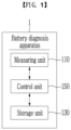
- FIG. 1 is a diagram illustrating a battery diagnosis apparatus according to an exemplary embodiment.
- a battery diagnosis apparatus 1 includes a measuring unit 110, a storage unit 130, and a control unit 150.
- the measuring unit 110 may measure a battery voltage, which is the voltage at both ends of the battery, and a battery current, which is the current flowing through the battery.
- the battery voltage and the battery current may be battery data required to calculate internal resistance of the battery.
- the internal resistance may include Direct Current Internal Resistance (DCIR).
- DCIR Direct Current Internal Resistance
- the measuring unit 110 may include a voltage sensor (not illustrated) electrically connected to both ends of the battery to measure the battery voltage and a current sensor (not illustrated) connected in series to the battery to measure the battery current.
- the measuring unit 110 may measure a battery voltage and a battery current at each diagnosis time point for diagnosing a defect in the battery, and transmit the measurement result to the control unit 150.
- the storage unit 130 may store an internal resistance value calculated by the control unit 150 based on at least one of a battery voltage and a battery current at each diagnosis time point for diagnosing a defect in the battery.
- the control unit 150 may store the battery voltage value and the battery current value received from the measuring unit 110 in the storage unit 130 at each diagnosis time point for diagnosing a defect in the battery.
- the control unit 150 calculates a moving average MA, an upper band threshold UB_Th which is larger than the moving average by a predetermined value, a lower band threshold LB_Th which is smaller than the moving average by a predetermined value, and an internal resistance value corresponding to the diagnosis time point N.
- a time point at which charging of the battery starts or a time point at which discharging of the battery ends may be a diagnosis time point N for diagnosing a defect in the battery.
- the measuring unit 110 may measure each of a battery voltage and a battery current at a predetermined cycle for a predetermined period of time, and transmit the measurement results to the control unit 150.
- the control unit 150 may extract a plurality of diagnosis time points included in the preset number of samples SN when counting the diagnosis time points in the direction of the previous diagnosis time point based on the current diagnosis time point N and determine a sample group.
- the number of samples SN is the number of a plurality of diagnosis time points included in the sample group, and may be determined as an optimal number based on an experiment or the like.
- the sample group is a subgroup of a plurality of past diagnosis time points, which is a population, and may be a group for calculating a moving average MA and an standard deviation average value ⁇ _ave, which will be described below.
- Table 1 is an example of the internal resistance DCIR value, the moving average MA, the upper band threshold UB_Th, and the lower band threshold LB_Th calculated at each of a plurality of diagnosis time points. It is assumed that the number of samples SN is 5.
- the values calculated on average according to the experiment may be replaced with the moving averages MA, standard deviations ⁇ , the standard deviation average value values ⁇ _ave, the upper band thresholds UB_Th, and the lower band thresholds LB_Th at the first diagnosis time points 1, 2, 3, .... (Table 1) Diagnosis period 1 ... N-7 N-6 N-5 N-4 N-3 N-2 N-1 N Internal resistance (DCIR) ... 25 27 23 24 20 21 23 1 Moving average (MA) ... 22.5 21 22 23.5 23 22 24 2 Standard deviation ( ⁇ ) ... 1.56 1.60 1.70 1.60 1.82 1.73 1.63 3 Average standard deviation ( ⁇ _ave) ... 1.55 1.62 1.65 1.62 1.70 1.65 1.55 4 Upper band threshold (UB_Th) ... 27.15 26.20 26.95 27.90 28.1 26.95 28.65 5 Lower band threshold (LB_Th) ... 17.85 15.8 17.05 19.1 17.9 17.05 19.35 6 Diagnosis result Normal Abnormal Normal Normal Normal Normal Normal Normal 7
- control unit 150 When the control unit 150 counts the diagnosis time point in the direction of the previous diagnosis time point based on the current diagnosis time point N, the control unit 150 may extract an N-1 th diagnosis time point, an N-2 th diagnosis time point, an N-3 th diagnosis time point, an N-4 th diagnosis time point, and an N-5 th diagnosis time point corresponding to the sample number SN of 5, and determine the sample group.
- the control unit 150 may determine a sample group by extracting a plurality of diagnosis time points (N-1, N-2, N-3, N-4, and N-5), and determine reference values (upper and lower band thresholds to be described below) used for defect diagnosis based on the internal resistance value calculated at each of the plurality of diagnosis time points belonging to the sample group. Then, it is possible to solve the problem of misdiagnosing the degree of aging due to longterm use of the battery and/or the temporary change in internal resistance value as a defect of the battery.
- control unit 150 determines the reference values (upper and lower band thresholds) for diagnosing defects in the battery at the N th diagnosis time point based on the internal resistance value calculated in each of the plurality of diagnosis time points N-5, N-4, N-3, N-2, and N-1 belonging to the sample group.
- the control unit 150 compares a value of the internal resistance DCIR N corresponding to the N th diagnosis time point N with the upper band threshold UB N _Th and the lower band threshold LB N _Th to diagnose a defect in the battery. For example, referring to Table 1, at the N th diagnosis time point N, the control unit 150 calculates the internal resistance value (1), the upper band threshold (5) and the lower band threshold (6), and compare the calculated internal resistance value (1) with the upper band threshold (5) and the lower band threshold (6) to diagnose the defect of the battery. In this case, in order to calculate the upper band threshold (5) and the lower band threshold (6), the moving average (2) and the standard deviation average value (4) are required.
- the standard deviation (3) is not a value necessary for defect diagnosis at the N th diagnosis time point N, but is necessary for defect diagnosis at the next diagnosis time points N+1, N+2,..., so that the standard deviation (3) may be calculated at the N th diagnosis time point and stored in the storage unit 130.
- the control unit 150 may calculate the internal resistance DCIR N value corresponding to the N th diagnosis time point N based on the battery voltage, which is the voltage of the both ends of the battery, and the battery current, which is the current flowing through the battery.
- the control unit 150 may calculate the internal resistance DCIR N value based on the charging current I flowing through the battery and the voltage difference ⁇ V. For example, it is assumed that the internal resistance DCIR N value corresponding to the N th diagnosis time point N is calculated as 30 ⁇ .
- MA N DCIR N ⁇ 5 + DCIR N ⁇ 4 + DCIR N ⁇ 3 + DCIR N ⁇ 2 + DCIR N ⁇ 1 SN
- control unit 150 may calculate a standard deviation ⁇ N (3) corresponding to the diagnosis time point N based on the internal resistance value DCIR and moving average MA corresponding to each of the plurality of diagnosis time points N-5, N-4, N-3, N-2, and N-1 belonging to the sample group.
- the standard deviation ⁇ N (3) corresponding to the N th diagnosis time point N is not a value necessary for defect diagnosis at the N th diagnosis time point N, but is necessary when defects are diagnosed at the next diagnosis time points N+1, N+2, and ... . Accordingly, the standard deviation ⁇ N (3) corresponding to the N th diagnosis time point N may be calculated at the N th diagnosis time point N and stored in the storage unit 130.
- control unit 150 may calculate an standard deviation average value ⁇ N _ ave (4) corresponding to the N th diagnosis time point N based on the plurality of standard deviations ⁇ N-5 , ⁇ N-4 , ⁇ N-3 , ⁇ N-2 , and ⁇ N-1 corresponding to the plurality of diagnosis time points N-5, N-4, N-3, N-2, and N-1, respectively, belonging to the sample group.
- the control unit 150 may calculate an upper band threshold UB N _Th that is larger than the moving average MA N by a predetermined value and a lower band threshold LB N _Th that is smaller than the moving average MA by a predetermined value.
- the control unit 150 may calculate a first error value by multiplying the standard deviation average value ⁇ N_ave by a predetermined first multiple, and calculate the upper band threshold UB N _Th by adding the first error value to the moving average MA N .
- the control unit 150 may calculate a second error value by multiplying the standard deviation average value ⁇ N _ ave by a predetermined second multiple, and calculate the lower band threshold LB N _Th by subtracting the second error value from the moving average MA N .
- the first multiple and the second multiple may be the same, but are not limited thereto, and the error value may be calculated as various multiples.
- the multiple Q is a value for reflecting a predetermined error, and may be determined by various values through experiments. For example, it is assumed that the multiple Q is the natural number 3.
- UB N _ Th MA N + ⁇ N _ ave ⁇ Q
- LB N _ Th MA N ⁇ ⁇ N _ ave ⁇ Q
- control unit 150 may compare the value of the internal resistance DCIR N corresponding to the N th diagnosis time point N with the upper band threshold UB N _Th and the lower band threshold LB N _Th corresponding to the N th diagnosis time point to diagnose a defect in the battery.
- the control unit 150 may diagnose that a disconnection defect (DD) has occurred in at least one of a plurality of battery cells included in the battery.
- DD disconnection defect
- the control unit 150 may diagnose that a short defect (SD) has occurred in at least one of a plurality of battery cells included in the battery.
- the control unit 150 may diagnose that a defect (disconnection defect or short defect) has occurred in the battery. In addition, when the value of the internal resistance DCIR N value falls within the normal range, the control unit 150 may diagnose the state of the battery as normal.
- the internal resistance DCIR N value, the upper band threshold UB N _Th, and the lower band threshold LB N _Th corresponding to the N th diagnosis time point N may be calculated as 30 ⁇ , 27.3, and 17.1, respectively.
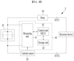
- FIG. 2 is a diagram illustrating a battery system according to another exemplary embodiment.
- a battery system 2 includes a battery 10, a relay 20, a current sensor 30, and a battery management system (BMS) 40.
- BMS battery management system
- the battery 10 may include a plurality of battery cells connected in series and/or in parallel. In FIG. 2 , three battery cells connected in parallel are illustrated, but the present invention is not limited thereto, and the battery 10 may include various numbers of battery cells connected in series and/or in parallel. In some exemplary embodiments, the battery cell may be a rechargeable secondary battery.
- a predetermined number of battery cells is connected in parallel to form a battery bank, and a predetermined number of battery banks is connected in series to form a battery pack to supply desired power to an external device.
- a predetermined number of battery cells is connected in parallel to form a battery bank, and a predetermined number of battery banks is connected in parallel to form a battery pack to supply desired power to an external device.
- the present invention is not limited to this connection, and the battery 10 may include a plurality of battery banks including a plurality of battery cells connected in series and/or parallel, and the plurality of battery banks may also be connected in series and/or parallel.
- the battery 10 is connected between the two output terminals OUT1 and OUT2 of the battery system 2.
- the relay 20 is connected between a positive electrode of the battery system 2 and the first output terminal OUT1
- the current sensor 30 is connected between a negative electrode of the battery system 2 and the second output terminal OUT2.
- the relay 20 controls electrical connection between the battery system 2 and an external device.
- the relay 20 When the relay 20 is turned on, the battery system 2 and the external device are electrically connected to perform charging or discharging, and when the relay 20 is turned off, the battery system 2 and the external device are electrically separated.
- the external device may be a charger in a charging cycle in which power is supplied to the battery 10 for charging, and may be a load in a discharging cycle in which the battery 10 discharges power to the external device.
- the current sensor 30 is connected in series to a current path between the battery 10 and an external device.
- the current sensor 30 may measure the battery current flowing through the battery 10, that is, a charging current and a discharging current, and transmit the measurement result to the BMS 40.
- the BMS 40 includes a measuring unit 41, a storage unit 43, and a control unit 45.
- the battery diagnosis apparatus 1 illustrated in FIG. 1 may correspond to the BMS 40 illustrated in FIG. 2 .
- the functions performed by the measuring unit 110, the storage unit 130, and the control unit 150 of the battery diagnosis apparatus 1 may correspond to the functions performed by the measuring unit 41, the storage unit 43, and the control unit 45 of the BMS 40.
- the battery diagnosis apparatus 1 may be configured separately from the battery system 1.
- the BMS 40 may perform the function of the battery diagnosis apparatus 1.
- the measuring unit 41 is electrically connected to both ends of the battery 10 to measure a battery current and a battery voltage.
- the measuring unit 41 may be implemented as an Application Specific Integrated Circuit (ASIC) that monitors the battery 10 and measures battery data (voltage, current, and the like) corresponding to the state of the battery 10.
- ASIC Application Specific Integrated Circuit
- the measuring unit 41 may collect the battery voltage by sensing voltage values of both ends of the battery 10.
- the measuring unit 41 may receive a battery current value from the current sensor 30.
- the measuring unit 41 may transmit the battery voltage value and the battery current value to the control unit 150.
- the storage unit 43 may store an internal resistance value calculated by the control unit 45 based on at least one of a battery voltage and a battery current at each diagnosis time point for diagnosing a defect in the battery 10.
- the control unit 45 may store the battery voltage value and the battery current value received from the measuring unit 41 in the storage unit 43 at each diagnosis time point for diagnosing a defect in the battery.
- the control unit 45 calculates a moving average MA N , an upper band threshold UB N _Th, a lower band threshold LB N _Th, and internal resistance DCIR N . Also, the control unit 45 may diagnose the state of the battery 10 by comparing the value of the internal resistance DCIR N with the upper band threshold UB N _Th and the lower band threshold LB N _Th.
- control unit 45 may extract a plurality of diagnosis time points included in the preset number of samples SN when counting the diagnosis time points in the direction of the previous diagnosis time point based on the current diagnosis time point N and determine a sample group.
- the number of samples SN is the number of a plurality of diagnosis time points included in the sample group, and may be determined as an optimal number based on an experiment or the like.
- the sample group is a subgroup of a plurality of past diagnosis time points, which is a population, and may be a group for calculating a moving average MA and an standard deviation average value ⁇ _ave, which will be described below.
- the control unit 45 may extract an N-1 th diagnosis time point, an N-2 th diagnosis time point, an N-3 th diagnosis time point, an N-4 th diagnosis time point, and an N-5 th diagnosis time point corresponding to the sample number SN of 5, and determine the sample group.
- the control unit 45 may calculate a moving average MA N , which is an average of internal resistance values of a sample group. For example, referring to Table 1 and Equation 2 above, the control unit 45 may calculate the moving average MA N of 22.2 corresponding to the current diagnosis time point N by averaging multiple internal resistance values 23 ⁇ , 24 ⁇ , 20 ⁇ , 21 ⁇ , and 23 ⁇ corresponding to a plurality of diagnosis time points N-5, N-4, N-3, N-2, and N-1, respectively, belonging to the sample group.
- control unit 45 may calculate an standard deviation average value ⁇ N_ave (1.70) corresponding to the current diagnosis time point N based on standard deviations ⁇ N-5 , ⁇ N-4 , ⁇ N-3 , ⁇ N-2 , ⁇ N-1 corresponding to the plurality of diagnosis time points N-5, N-4, N-3, N-2, and N-1, respectively, belonging to the sample group.
- the control unit 45 may determine a reference value for diagnosing a battery defect at the current diagnosis time point N, that is, the N th diagnosis time point, based on the internal resistance DCIR N value calculated at each of a plurality of diagnosis time points N-5, N-4, N-3, N-2, and N-1 belonging to the sample group.
- the reference value may include an upper band threshold UB N _Th and a lower band threshold LB N _Th.
- the control unit 45 may calculate an upper band threshold UB N _Th that is larger than the moving average MA N by a predetermined value and a lower band threshold LB N _Th that is smaller than the moving average MA by a predetermined value.
- the control unit 45 may calculate a first error value by multiplying the standard deviation average value ⁇ N_ave by a predetermined first multiple, and calculate the upper band threshold UB N _Th by adding the first error value to the moving average MA N .
- the control unit 45 may calculate a second error value by multiplying the standard deviation average value ⁇ N _ ave by a predetermined second multiple, and calculate the lower band threshold LB N _Th by subtracting the second error value from the moving average MA N .
- the first multiple and the second multiple may be the same, but are not limited thereto, and the error value may be calculated as various multiples.
- the multiple Q is a value for reflecting a predetermined error, and may be determined by various values through experiments.
- control unit 45 may compare the value of the internal resistance DCIR N corresponding to the N th diagnosis time point N with the upper band threshold UB N _Th and the lower band threshold LB N _Th corresponding to the N th diagnosis time point to diagnose a defect in the battery 10.
- the control unit 45 may diagnose that a disconnection defect (DD) has occurred in at least one of a plurality of battery cells included in the battery 10.
- DD disconnection defect
- LB N _Th the control unit 45 may diagnose that a short defect (SD) has occurred in at least one of a plurality of battery cells included in the battery 10.
- the control unit 45 may diagnose that a defect (disconnection defect or short defect) has occurred in the battery 10. In addition, when the value of the internal resistance DCIR N value falls within the normal range, the control unit 45 may diagnose the state of the battery as normal.
- the internal resistance DCIR N value, the upper band threshold UB N _Th, and the lower band threshold LB N _Th corresponding to the N th diagnosis time point N may be calculated as 30 ⁇ , 27.3, and 17.1, respectively.
- FIG. 3 is an exemplary diagram in which a moving average, an upper band threshold, and a lower band threshold calculated for each of a plurality of diagnosis time points are accumulated and displayed.
- the BMS 40 may determine a sample group by extracting a plurality of diagnosis time points which is adjacent to the diagnosis time point N while being in an environment similar to the predetermined diagnosis time point N.
- the BMS 40 may calculate an upper band threshold UB N _Th and a lower band threshold LB N _Th corresponding to the diagnosis time point N based on the moving average MA N , which is the average of a plurality of internal resistance values belonging to the sample group, and the standard deviation average value ⁇ N _ ave , which is the average of a plurality of standard deviations.
- the BMS 40 may extract an N-1 th diagnosis time point, an N-2 th diagnosis time point, an N-3 th diagnosis time point, an N-4 th diagnosis time point, and an N-5 th diagnosis time point corresponding to the sample number SN of 5.
- the BMS 40 may calculate the upper band threshold 27.3 and the lower band threshold 17.1.
- the BMS 40 may diagnose a defect in the battery 10 by comparing the value of the internal resistance DCIR N with the upper band threshold UB N _Th and the lower band threshold LB N _Th. In this case, it is assumed that the internal resistance DCIR N is 30 ⁇ , for example.
- the internal resistance band (DCIR Band) illustrated in FIG. 3 may be derived by connecting the moving average MA, the upper band threshold UB_Th, and the lower band threshold LB_Th calculated at each diagnosis time point.
- the internal resistance band (DCIR Band) may exhibit a trend of an internal resistance value that changes as the battery 10 is used.
- FIG. 4 is a flowchart illustrating a battery diagnosis method according to an exemplary embodiment.
- the BMS 40 collects battery data (S100).
- the battery data may include a battery voltage, which is a voltage of both ends of the battery 10, and a battery current, which is a current flowing through the battery 10.
- the battery voltage and the battery current may be battery data required to calculate Direct Current Internal Resistance (DCIR) of the battery.
- DCIR Direct Current Internal Resistance
- the BMS 40 determines a sample group by extracting a plurality of diagnosis time points adjacent to a predetermined diagnosis time point N (S200).
- the BMS 40 may extract a plurality of diagnosis time points corresponding to the preset number of samples SN to determine a sample group.
- the BMS 40 may extract an N-1 th diagnosis time point, an N-2 th diagnosis time point, an N-3 th diagnosis time point, an N-4 th diagnosis time point, and an N-5 th diagnosis time point corresponding to the sample number SN of 5, and determine the sample group.
- the BMS 40 determines a reference value for the diagnosis of a defect of the battery 10 (S300).
- the reference value may include an upper band threshold UB N _Th and a lower band threshold LB N _Th.
- the BMS 40 averages internal resistance values corresponding to a plurality of diagnosis time points belonging to the sample group to calculate a moving average MA N of the sample group (S310).
- the BMS 40 may calculate the moving average MA N of 22.2 corresponding to the diagnosis time point N by averaging multiple internal resistance values 23 ⁇ , 24 ⁇ , 20 ⁇ , 21 ⁇ , and 23 ⁇ corresponding to a plurality of diagnosis time points N-5, N-4, N-3, N-2, and N-1, respectively, belonging to the sample group.
- the BMS 40 calculates an error value E based on the standard deviation average value ⁇ N _ ave of the sample group (S320).
- the standard deviation average value ⁇ N _ ave of the sample group may be calculated by averaging the plurality of standard deviations ⁇ N-5 , ⁇ N-4 , ⁇ N-3 , ⁇ N-2 , and ⁇ N-1 corresponding to the plurality of diagnosis time points N-5, N-4, N-3, N-2, and N-1, respectively, belonging to the sample group.
- the BMS 40 may calculate an standard deviation average value ⁇ N _ ave of 1.70 corresponding to the N th diagnosis time point N based on the plurality of standard deviations ⁇ N-5 , ⁇ N-4 , ⁇ N-3 , ⁇ N-2 , and ⁇ N-1 corresponding to the plurality of diagnosis time points N-5, N-4, N-3, N-2, and N-1, respectively, belonging to the sample group.
- the multiple Q is a value for reflecting a predetermined error, and may be determined by various values through experiments. For example, it is assumed that the multiple Q is the natural number 3.
- the BMS 40 calculates an upper band threshold UB N _Th and a lower band threshold LB N _Th based on the moving average MA N and the error value E (S330).
- the BMS 40 compares the value of the internal resistance DCIR N corresponding to the current diagnosis time point N with the upper band threshold UB N _Th and the lower band threshold LB N _Th corresponding to the current diagnosis time point N, so that the battery 10 diagnoses a defect of the battery 10 (S400).
- the BMS 40 may calculate the internal resistance DCIR N value corresponding to the N th diagnosis time point based on the battery voltage, which is the voltage of the both ends of the battery, and the battery current, which is the current flowing through the battery. Also, the value of the internal resistance DCIR N may be calculated in operation S200 or operation S300.
- the BMS 40 may calculate the internal resistance DCIR N value based on the charging current I flowing through the battery 10 and the voltage difference ⁇ V. For example, it is assumed that the internal resistance DCIR N value corresponding to the N th diagnosis time point is calculated as 30 ⁇ .
- the BMS 40 determines whether the value of the internal resistance DCIR N exceeds the upper band threshold UB N _Th (S410).
- the BMS 40 diagnoses that a disconnection defect has occurred in at least one of a plurality of battery cells included in the battery 10 (S420).
- the internal resistance value of the battery 10 may increase.
- the BMS 40 determines whether the internal resistance DCIR N value is less than the lower band threshold LB N _Th (S430).
- the BMS 40 diagnoses that a short defect has occurred in at least one of a plurality of battery cells included in the battery 10 (S440).
- the internal resistance value that is the entire resistance of the battery 10 may increase.
- the BMS 40 may diagnose the state of the battery 10 as a defect (disconnection defect or short defect). In addition, when the value of the internal resistance DCIR N value falls within the normal range, the BMS 40 may diagnose the state of the battery as normal.
Landscapes
- Physics & Mathematics (AREA)
- General Physics & Mathematics (AREA)
- Secondary Cells (AREA)
- Charge And Discharge Circuits For Batteries Or The Like (AREA)
- Tests Of Electric Status Of Batteries (AREA)
- Testing Electric Properties And Detecting Electric Faults (AREA)
Abstract
Description
- This application claims priority to and the benefit of
Korean Patent Application No. 10-2022-0061920 filed in the Korean Intellectual Property Office on May 20, 2022 - The present invention relates to a battery diagnosis method capable of diagnosing the state of a battery including a plurality of battery cells that are connected in parallel, and to a battery diagnosis apparatus and a battery system for providing the method.
- Large batteries mounted on electric vehicles, energy storage batteries, robots, satellites, and the like are required to have a higher capacity than small batteries mounted on portable terminals, laptop computers, and the like. A high-capacity battery may be configured by connecting a plurality of batteries in series and/or in parallel. In this case, the plurality of batteries may include a plurality of battery cells connected in parallel.
- Meanwhile, when the number of battery cells included in a battery increases, defects may occur in the battery due to problems in the battery cells themselves and/or problems in connection between battery cells. For example, defects, such as disconnection and short circuit, between battery cells may occur. When a defect occurs in a battery, it is necessary to enable a system (for example, a vehicle, and an energy storage device) in which the battery is mounted to operate normally through quick diagnosis and correction of the defect.
- However, when a plurality of battery cells is connected in parallel, it is not easy to directly sense a cell voltage or the like of an individual battery cell due to a structural problem in connection and the like. That is, it is difficult to diagnose defects of the entire battery by directly estimating defects of the battery cells themselves.
- In addition, a technology for diagnosing a defect in a battery by estimating Direct Current Internal Resistance (DCIR) on a battery basis and comparing the estimated DCIR value with a preset (fixed) reference value has a limitation in not detecting a defect when a plurality of battery cells in a battery is disconnected or shorted at the same time. In addition, a problem of erroneously diagnosing the degree of change in the DC internal resistance value according to aging as occurrence of a defect.
- The present invention is conceived to solve the above problems, and provides a battery diagnosis method capable of precisely diagnosing the state of a battery including a plurality of battery cells that are connected in parallel, and a battery system providing the method.
- A battery diagnosis apparatus according to an embodiment of the present invention includes: a measuring unit configured to measure a battery voltage at opposite ends of a battery including a plurality of battery cells, and a battery current flowing through the battery; a storage unit configured to store an internal resistance value of the battery that is calculated based on at least one of the battery voltage and the battery current at each diagnosis time point; and a control unit configured to extract a plurality of previous diagnosis time points corresponding to a predetermined number of samples based on a diagnosis time point for the each diagnosis time point, calculate a moving average that is an average of a plurality of internal resistance values corresponding to the plurality of diagnosis time points, respectively, the plurality of internal resistance value including the internal resistance value, and compare the internal resistance value with an upper band threshold that is larger than the moving average by a predetermined value and a lower band threshold that is smaller than the moving average by a predetermined value to diagnose a defect in the battery.
- The control unit may calculate an error value by multiplying a standard deviation average value, which is an average of a plurality of standard deviations corresponding to the plurality of diagnosis time points, respectively, by a predetermined multiple, calculate the upper band threshold by adding the error value to the moving average, and calculate the lower band threshold by subtracting the error value from the moving average.
- When the internal resistance value exceeds the upper band threshold, the control unit may diagnose that a disconnection defect has occurred in at least one of the plurality of battery cells.
- When the internal resistance value is less than the lower band threshold, the control unit may diagnose that a short defect has occurred in at least one of the plurality of battery cells.
- When the internal resistance value is within a range that is equal to or greater than the lower band threshold and is equal to or less than the upper band threshold, the control unit may diagnose that the plurality of battery cells is in a normal state.
- A battery system according to another embodiment of the present invention includes: a battery including a plurality of battery cells; a measuring unit configured to measure a battery voltage at opposite ends of the battery, and a battery current flowing through the battery; a storage unit configured to store an internal resistance value of the battery calculated based on the battery voltage and the battery current at each diagnosis time point; and a control unit configured to extract a plurality of previous diagnosis time points corresponding to a predetermined number of samples based on a diagnosis time point for the each diagnosis time point, calculate a moving average that is an average of a plurality of internal resistance values corresponding to the plurality of diagnosis time points, respectively, the plurality of internal resistance values including the internal resistance value, and compare the internal resistance value with an upper band threshold that is larger than the moving average by a predetermined value and a lower band threshold that is smaller than the moving average by a predetermined value to diagnose a defect in the battery.
- The control unit may further calculate an error value by multiplying a standard deviation average value, which is an average of a plurality of standard deviations corresponding to the plurality of diagnosis time points, respectively, by a predetermined multiple, calculate the upper band threshold by adding the error value to the moving average, and calculate the lower band threshold by subtracting the error value from the moving average.
- When the internal resistance value exceeds the upper band threshold, the control unit may diagnose that a disconnection defect has occurred in at least one of the plurality of battery cells.
- When the internal resistance value is less than the lower band threshold, the control unit may diagnose that a short defect has occurred in at least one of the plurality of battery cells.
- A battery diagnosing method according to still another embodiment of the present invention includes: a battery data collecting operation of collecting a measurement value of each of a battery voltage at opposite ends of a battery including a plurality of battery cells, and a battery current flowing through the battery; a sample group determining operation of extracting, at a predetermined diagnosis time point, a plurality of diagnosis time points previously obtained and corresponding to a number of samples based on the predetermined diagnosis time point; a reference value determining operation of calculating a moving average, which is an average of a plurality of internal resistance values corresponding to the plurality of diagnosis time points, respectively, an upper band threshold larger than the moving average by a predetermined value, and a lower band threshold smaller than the moving average by a predetermined value; and a defect diagnosis operation of diagnosing a defect in the battery by comparing an internal resistance value corresponding to the predetermined diagnosis time point with the upper band threshold and the lower band threshold, from among the plurality of internal resistance values.
- The reference value determining operation may include calculating an error value by multiplying a standard deviation average value, which is an average of a plurality of standard deviations corresponding to the plurality of diagnosis time points, respectively, by a predetermined multiple, calculating the upper band threshold by adding the error value to the moving average, and calculating the lower band threshold by subtracting the error value from the moving average.
- The defect diagnosing operation may include, when the internal resistance value exceeds the upper band threshold, diagnosing that a disconnection defect has occurred in at least one of the plurality of battery cells.
the defect diagnosing operation may include, when the internal resistance value is less than the lower band threshold, diagnosing that a short defect has occurred in at least one of the plurality of battery cells. - According to the present invention, even when a plurality of battery cells is connected in parallel, it is possible to diagnose a battery defect with high precision.
- Unlike the prior art of diagnosing a defects in a battery by using a fixed reference value, the present invention diagnoses the battery defect by setting a reference value that reflects the change in the battery's internal resistance value at each diagnosis time point for diagnosing the battery defect, so that the degree of deterioration according to the period of use of the battery is considered, thereby diagnosing the defect in the battery with high precision.
-
-
FIG. 1 is a diagram illustrating a battery diagnosis apparatus according to an exemplary embodiment. -
FIG. 2 is a diagram illustrating a battery system according to another exemplary embodiment. -
FIG. 3 is an exemplary diagram in which a moving average, an upper band threshold, and a lower band threshold calculated for each of a plurality of diagnosis time points are accumulated and displayed. -
FIG. 4 is a flowchart illustrating a battery diagnosis method according to an exemplary embodiment. -
FIG. 5 is a flowchart illustrating a reference value determining operation S300 ofFIG. 4 in detail. - Hereinafter, an exemplary embodiment disclosed the present specification will be described in detail with reference to the accompanying drawings, and the same or similar constituent element is denoted by the same reference numeral regardless of a reference numeral, and a repeated description thereof will be omitted. Suffixes, "module" and and/or "unit" for a constituent element used for the description below are given or mixed in consideration of only easiness of the writing of the specification, and the suffix itself does not have a discriminated meaning or role. Further, in describing the exemplary embodiment disclosed in the present disclosure, when it is determined that detailed description relating to well-known functions or configurations may make the subject matter of the exemplary embodiment disclosed in the present disclosure unnecessarily ambiguous, the detailed description will be omitted. Further, the accompanying drawings are provided for helping to easily understand exemplary embodiments disclosed in the present specification, and the technical spirit disclosed in the present specification is not limited by the accompanying drawings, and it will be appreciated that the present invention includes all of the modifications, equivalent matters, and substitutes included in the spirit and the technical scope of the present invention.
- Terms including an ordinary number, such as first and second, are used for describing various constituent elements, but the constituent elements are not limited by the terms. The terms are used only to discriminate one constituent element from another constituent element.
- It should be understood that when one constituent element is referred to as being "coupled to" or "connected to" another constituent element, one constituent element can be directly coupled to or connected to the other constituent element, but intervening elements may also be present. By contrast, when one constituent element is referred to as being "directly coupled to" or "directly connected to" another constituent element, it should be understood that there are no intervening elements.
- In the present application, it will be appreciated that terms "including" and "having" are intended to designate the existence of characteristics, numbers, operations, operations, constituent elements, and components described in the specification or a combination thereof, and do not exclude a possibility of the existence or addition of one or more other characteristics, numbers, operations, operations, constituent elements, and components, or a combination thereof in advance.
-
FIG. 1 is a diagram illustrating a battery diagnosis apparatus according to an exemplary embodiment. - Referring to
FIG. 1 , abattery diagnosis apparatus 1 includes ameasuring unit 110, astorage unit 130, and acontrol unit 150. - The
measuring unit 110 may measure a battery voltage, which is the voltage at both ends of the battery, and a battery current, which is the current flowing through the battery. The battery voltage and the battery current may be battery data required to calculate internal resistance of the battery. For example, the internal resistance may include Direct Current Internal Resistance (DCIR). - The
measuring unit 110 may include a voltage sensor (not illustrated) electrically connected to both ends of the battery to measure the battery voltage and a current sensor (not illustrated) connected in series to the battery to measure the battery current. For example, themeasuring unit 110 may measure a battery voltage and a battery current at each diagnosis time point for diagnosing a defect in the battery, and transmit the measurement result to thecontrol unit 150. - The
storage unit 130 may store an internal resistance value calculated by thecontrol unit 150 based on at least one of a battery voltage and a battery current at each diagnosis time point for diagnosing a defect in the battery. In addition, thecontrol unit 150 may store the battery voltage value and the battery current value received from themeasuring unit 110 in thestorage unit 130 at each diagnosis time point for diagnosing a defect in the battery. - When a diagnosis time point N according to a preset condition arrives, the
control unit 150 calculates a moving average MA, an upper band threshold UB_Th which is larger than the moving average by a predetermined value, a lower band threshold LB_Th which is smaller than the moving average by a predetermined value, and an internal resistance value corresponding to the diagnosis time point N. - Depending on the exemplary embodiment, a time point at which charging of the battery starts or a time point at which discharging of the battery ends may be a diagnosis time point N for diagnosing a defect in the battery. When the diagnosis time point N arrives, the
measuring unit 110 may measure each of a battery voltage and a battery current at a predetermined cycle for a predetermined period of time, and transmit the measurement results to thecontrol unit 150. - First of all, the
control unit 150 may extract a plurality of diagnosis time points included in the preset number of samples SN when counting the diagnosis time points in the direction of the previous diagnosis time point based on the current diagnosis time point N and determine a sample group. In this case, the number of samples SN is the number of a plurality of diagnosis time points included in the sample group, and may be determined as an optimal number based on an experiment or the like. The sample group is a subgroup of a plurality of past diagnosis time points, which is a population, and may be a group for calculating a moving average MA and an standard deviation average value σ_ave, which will be described below. - Hereinafter, Table 1 is an example of the internal resistance DCIR value, the moving average MA, the upper band threshold UB_Th, and the lower band threshold LB_Th calculated at each of a plurality of diagnosis time points. It is assumed that the number of samples SN is 5.
- For reference, in Table 1, it may be difficult to directly calculate a moving average MA, a standard deviation σ, an standard deviation average value σ_ave, an upper band threshold UB_Th, and a lower band threshold LB_Th of the first diagnosis time point 1 (therefore, the corresponding values in Table 1 are marked with blanks). In addition, it may also be difficult to directly calculate moving averages MA, standard deviations σ, standard deviation average values σ_ave, upper band thresholds UB_Th, and lower band thresholds LB_Th at
diagnosis time points diagnosis time point 1 because there are no or insufficient past diagnostic values for calculation. In this case, the values calculated on average according to the experiment may be replaced with the moving averages MA, standard deviations σ, the standard deviation average value values σ_ave, the upper band thresholds UB_Th, and the lower band thresholds LB_Th at the firstdiagnosis time points (Table 1) Diagnosis period 1 ... N-7 N-6 N-5 N-4 N-3 N-2 N-1 N Internal resistance (DCIR) ... 25 27 23 24 20 21 23 ① Moving average (MA) ... 22.5 21 22 23.5 23 22 24 ② Standard deviation (σ) ... 1.56 1.60 1.70 1.60 1.82 1.73 1.63 ③ Average standard deviation (σ_ave) ... 1.55 1.62 1.65 1.62 1.70 1.65 1.55 ④ Upper band threshold (UB_Th) ... 27.15 26.20 26.95 27.90 28.1 26.95 28.65 ⑤ Lower band threshold (LB_Th) ... 17.85 15.8 17.05 19.1 17.9 17.05 19.35 ⑥ Diagnosis result Normal Abnormal Normal Normal Normal Normal Normal ⑦ - When the
control unit 150 counts the diagnosis time point in the direction of the previous diagnosis time point based on the current diagnosis time point N, thecontrol unit 150 may extract an N-1th diagnosis time point, an N-2th diagnosis time point, an N-3th diagnosis time point, an N-4th diagnosis time point, and an N-5th diagnosis time point corresponding to the sample number SN of 5, and determine the sample group. - The
control unit 150 may determine a sample group by extracting a plurality of diagnosis time points (N-1, N-2, N-3, N-4, and N-5), and determine reference values (upper and lower band thresholds to be described below) used for defect diagnosis based on the internal resistance value calculated at each of the plurality of diagnosis time points belonging to the sample group. Then, it is possible to solve the problem of misdiagnosing the degree of aging due to longterm use of the battery and/or the temporary change in internal resistance value as a defect of the battery. - Next, the
control unit 150 determines the reference values (upper and lower band thresholds) for diagnosing defects in the battery at the Nth diagnosis time point based on the internal resistance value calculated in each of the plurality of diagnosis time points N-5, N-4, N-3, N-2, and N-1 belonging to the sample group. - According to the exemplary embodiment, the
control unit 150 compares a value of the internal resistance DCIRN corresponding to the Nth diagnosis time point N with the upper band threshold UBN_Th and the lower band threshold LBN_Th to diagnose a defect in the battery. For example, referring to Table 1, at the Nth diagnosis time point N, thecontrol unit 150 calculates the internal resistance value (①), the upper band threshold (⑤) and the lower band threshold (⑥), and compare the calculated internal resistance value (①) with the upper band threshold (⑤) and the lower band threshold (⑥) to diagnose the defect of the battery. In this case, in order to calculate the upper band threshold (⑤) and the lower band threshold (⑥), the moving average (②) and the standard deviation average value (④) are required. However, the standard deviation (③) is not a value necessary for defect diagnosis at the Nth diagnosis time point N, but is necessary for defect diagnosis at the next diagnosis time points N+1, N+2,..., so that the standard deviation (③) may be calculated at the Nth diagnosis time point and stored in thestorage unit 130. - Hereinafter, the internal resistance value (①), the moving average (②), the standard deviation (③), the standard deviation average value (④), the upper band threshold (⑤), and the lower band threshold (⑥) calculated by the
control unit 150 at the Nth diagnosis time point N in Table 1 will be described. - The
control unit 150 may calculate the internal resistance DCIRN value corresponding to the Nth diagnosis time point N based on the battery voltage, which is the voltage of the both ends of the battery, and the battery current, which is the current flowing through the battery. For example, the value of the internal resistance DCIRN (①) may be calculated by Equation (1) below.
- For example, the
control unit 150 may calculate a voltage difference (ΔV = IV1 - V21) between a battery voltage V1 corresponding to a first time point when charging starts and a battery voltage V2 corresponding to a second time point after a predetermined time has elapsed from the first time point. Thecontrol unit 150 may calculate the internal resistance DCIRN value based on the charging current I flowing through the battery and the voltage difference ΔV. For example, it is assumed that the internal resistance DCIRN value corresponding to the Nth diagnosis time point N is calculated as 30Ω. - Referring to Table 1, the
control unit 150 may calculate an moving average MAN (②) corresponding to the diagnosis time point N by averaging (23Ω+ 24Ω+ 20Ω+ 21Ω+ 23Ω/5 = 22.2 Ω) the plurality of internal resistance values (23Ω, 24Ω, 20Ω, 21Ω, and 23Ω) corresponding to the plurality of diagnosis time points (N-5, N-4, N-3, N-2, and N-1), respectively, belonging to the sample group. That is, the internal resistance DCIRN value corresponding to the Nth diagnosis time point may be 22.2Ω.
- Referring to Table 2 below, the
control unit 150 may calculate a standard deviation σN (③) corresponding to the diagnosis time point N based on the internal resistance value DCIR and moving average MA corresponding to each of the plurality of diagnosis time points N-5, N-4, N-3, N-2, and N-1 belonging to the sample group.(Table 2) N-5 N-4 N-3 N-2 N-1 N Internal resistance (DCIR) 23 24 20 21 23 |DCIR-MA| |23-22.2| = 0.8 124-22.21 = 1.8 120-22.21 = 2.2 |21-22.2| = 1.2 |23-22.2| = 0.8 (DCIR-MA)2 (0.8)2 = 0.64 (1.8)2 = 3.24 (2.2)2 = 4.84 (1.2)2 = 1.44 (0.8)2 = 0.64 Variance (0.64 + 3.24 + 4.84 + 1.44 + 0.64)/5 = 2.16 Standard deviation (σN) 
1.41 - As described above, the standard deviation σN (③) corresponding to the Nth diagnosis time point N is not a value necessary for defect diagnosis at the Nth diagnosis time point N, but is necessary when defects are diagnosed at the next diagnosis time points N+1, N+2, and ... . Accordingly, the standard deviation σN (③) corresponding to the Nth diagnosis time point N may be calculated at the Nth diagnosis time point N and stored in the
storage unit 130. - Referring to Table 3 below, the
control unit 150 may calculate an standard deviation average value σ N_ave (④) corresponding to the Nth diagnosis time point N based on the plurality of standard deviations σN-5, σN-4, σN-3, σN-2, and σN-1 corresponding to the plurality of diagnosis time points N-5, N-4, N-3, N-2, and N-1, respectively, belonging to the sample group.(Table 3) N-5 N-4, N-3 N-2 N-1 N Standard deviation (σ) 1.70 1.60 1.82 1.73 1.63 Average standard deviation (σN_ave) (1.70 + 1.60 + 1.82 + 1.73 + 1.63)/5 = 1.696 1.70 - The
control unit 150 may calculate an upper band threshold UBN_Th that is larger than the moving average MAN by a predetermined value and a lower band threshold LBN_Th that is smaller than the moving average MA by a predetermined value. According to the exemplary embodiment, thecontrol unit 150 may calculate a first error value by multiplying the standard deviation average value σ N_ave by a predetermined first multiple, and calculate the upper band threshold UBN_Th by adding the first error value to the moving average MAN. In addition, thecontrol unit 150 may calculate a second error value by multiplying the standard deviation average value σ N_ave by a predetermined second multiple, and calculate the lower band threshold LBN_Th by subtracting the second error value from the moving average MAN. In this case, the first multiple and the second multiple may be the same, but are not limited thereto, and the error value may be calculated as various multiples. - According to the exemplary embodiment, the
control unit 150 may calculate an error value (E = σ N_ave × Q) by multiplying the standard deviation average value σ N_ave by a predetermined multiple Q. In this case, the multiple Q is a value for reflecting a predetermined error, and may be determined by various values through experiments. For example, it is assumed that the multiple Q is thenatural number 3. - The
control unit 150 may calculate the upper band threshold UBN_Th of 27.3 by adding the error value ((E = σ N_ave × Q = 1.70 × 3 = 5.1) to the moving average (MAN = 22.2) of the sample group as illustrated inEquation 3 below. In addition, thecontrol unit 150 may calculate the lower band threshold LBN_Th of 17.1 by subtracting the error value (E = σ N_ave × Q = 1.70 × 3 = 5.1) from the moving average (MAN = 22.2) of the sample group as illustrated inEquation 4 below.

- Next, the
control unit 150 may compare the value of the internal resistance DCIRN corresponding to the Nth diagnosis time point N with the upper band threshold UBN_Th and the lower band threshold LBN_Th corresponding to the Nth diagnosis time point to diagnose a defect in the battery. - According to the exemplary embodiment, when the internal resistance DCIRN value exceeds the upper band threshold UBN_Th, the
control unit 150 may diagnose that a disconnection defect (DD) has occurred in at least one of a plurality of battery cells included in the battery. When the value of the internal resistance DCIRN value is less than the lower band threshold LBN_Th, thecontrol unit 150 may diagnose that a short defect (SD) has occurred in at least one of a plurality of battery cells included in the battery. That is, when the value of the internal resistance DCIRN value is out of the normal range corresponding to the lower band threshold LBN_Th or more and the upper band threshold UBN_Th or less, thecontrol unit 150 may diagnose that a defect (disconnection defect or short defect) has occurred in the battery. In addition, when the value of the internal resistance DCIRN value falls within the normal range, thecontrol unit 150 may diagnose the state of the battery as normal. - For example, as described above through Tables 1 and 3 and
Equations 1 to 4, the internal resistance DCIRN value, the upper band threshold UBN_Th, and the lower band threshold LBN_Th corresponding to the Nth diagnosis time point N may be calculated as 30Ω, 27.3, and 17.1, respectively. In this case, thecontrol unit 150 may diagnose a battery defect (disconnection defect) based on the fact that the internal resistance value (DCIRN = 30) exceeds the upper band threshold (UBN_Th = 27.3). -
FIG. 2 is a diagram illustrating a battery system according to another exemplary embodiment. - Referring to
FIG. 2 , abattery system 2 includes abattery 10, arelay 20, acurrent sensor 30, and a battery management system (BMS) 40. - The
battery 10 may include a plurality of battery cells connected in series and/or in parallel. InFIG. 2 , three battery cells connected in parallel are illustrated, but the present invention is not limited thereto, and thebattery 10 may include various numbers of battery cells connected in series and/or in parallel. In some exemplary embodiments, the battery cell may be a rechargeable secondary battery. - For example, in the
battery 10, a predetermined number of battery cells is connected in parallel to form a battery bank, and a predetermined number of battery banks is connected in series to form a battery pack to supply desired power to an external device. For another example, in thebattery 10, a predetermined number of battery cells is connected in parallel to form a battery bank, and a predetermined number of battery banks is connected in parallel to form a battery pack to supply desired power to an external device. However, the present invention is not limited to this connection, and thebattery 10 may include a plurality of battery banks including a plurality of battery cells connected in series and/or parallel, and the plurality of battery banks may also be connected in series and/or parallel. - In
FIG. 2 , thebattery 10 is connected between the two output terminals OUT1 and OUT2 of thebattery system 2. In addition, therelay 20 is connected between a positive electrode of thebattery system 2 and the first output terminal OUT1, and thecurrent sensor 30 is connected between a negative electrode of thebattery system 2 and the second output terminal OUT2. The configurations illustrated inFIG. 2 and the connection relationship between the configurations are examples, but the invention is not limited thereto. - The
relay 20 controls electrical connection between thebattery system 2 and an external device. When therelay 20 is turned on, thebattery system 2 and the external device are electrically connected to perform charging or discharging, and when therelay 20 is turned off, thebattery system 2 and the external device are electrically separated. In this case, the external device may be a charger in a charging cycle in which power is supplied to thebattery 10 for charging, and may be a load in a discharging cycle in which thebattery 10 discharges power to the external device. - The
current sensor 30 is connected in series to a current path between thebattery 10 and an external device. Thecurrent sensor 30 may measure the battery current flowing through thebattery 10, that is, a charging current and a discharging current, and transmit the measurement result to theBMS 40. - The
BMS 40 includes a measuringunit 41, astorage unit 43, and acontrol unit 45. Thebattery diagnosis apparatus 1 illustrated inFIG. 1 may correspond to theBMS 40 illustrated inFIG. 2 . Specifically, the functions performed by the measuringunit 110, thestorage unit 130, and thecontrol unit 150 of thebattery diagnosis apparatus 1 may correspond to the functions performed by the measuringunit 41, thestorage unit 43, and thecontrol unit 45 of theBMS 40. For example, thebattery diagnosis apparatus 1 may be configured separately from thebattery system 1. For another example, in thebattery system 1 as illustrated inFIG. 2 , theBMS 40 may perform the function of thebattery diagnosis apparatus 1. - The measuring
unit 41 is electrically connected to both ends of thebattery 10 to measure a battery current and a battery voltage. For example, the measuringunit 41 may be implemented as an Application Specific Integrated Circuit (ASIC) that monitors thebattery 10 and measures battery data (voltage, current, and the like) corresponding to the state of thebattery 10. - For example, the measuring
unit 41 may collect the battery voltage by sensing voltage values of both ends of thebattery 10. The measuringunit 41 may receive a battery current value from thecurrent sensor 30. The measuringunit 41 may transmit the battery voltage value and the battery current value to thecontrol unit 150. - The
storage unit 43 may store an internal resistance value calculated by thecontrol unit 45 based on at least one of a battery voltage and a battery current at each diagnosis time point for diagnosing a defect in thebattery 10. In addition, thecontrol unit 45 may store the battery voltage value and the battery current value received from the measuringunit 41 in thestorage unit 43 at each diagnosis time point for diagnosing a defect in the battery. - When the diagnosis time point N according to a preset condition arrives, the
control unit 45 calculates a moving average MAN, an upper band threshold UBN_Th, a lower band threshold LBN_Th, and internal resistance DCIRN. Also, thecontrol unit 45 may diagnose the state of thebattery 10 by comparing the value of the internal resistance DCIRN with the upper band threshold UBN_Th and the lower band threshold LBN_Th. - First of all, the
control unit 45 may extract a plurality of diagnosis time points included in the preset number of samples SN when counting the diagnosis time points in the direction of the previous diagnosis time point based on the current diagnosis time point N and determine a sample group. In this case, the number of samples SN is the number of a plurality of diagnosis time points included in the sample group, and may be determined as an optimal number based on an experiment or the like. The sample group is a subgroup of a plurality of past diagnosis time points, which is a population, and may be a group for calculating a moving average MA and an standard deviation average value σ_ave, which will be described below. - For example, it is assumed that the number of samples SN is 5. In Table 1 above, when the
control unit 45 counts the diagnosis time point in the direction of the previous diagnosis time point based on the current diagnosis time point N, thecontrol unit 45 may extract an N-1th diagnosis time point, an N-2th diagnosis time point, an N-3th diagnosis time point, an N-4th diagnosis time point, and an N-5th diagnosis time point corresponding to the sample number SN of 5, and determine the sample group. - The
control unit 45 may calculate a moving average MAN, which is an average of internal resistance values of a sample group. For example, referring to Table 1 andEquation 2 above, thecontrol unit 45 may calculate the moving average MAN of 22.2 corresponding to the current diagnosis time point N by averaging multiple internal resistance values 23Ω, 24Ω, 20Ω, 21Ω, and 23Ω corresponding to a plurality of diagnosis time points N-5, N-4, N-3, N-2, and N-1, respectively, belonging to the sample group. - For example, referring to Table 1 and Table 3 above, the
control unit 45 may calculate an standard deviation average value σ N_ave (1.70) corresponding to the current diagnosis time point N based on standard deviations σN-5, σN-4, σN-3, σN-2, σN-1 corresponding to the plurality of diagnosis time points N-5, N-4, N-3, N-2, and N-1, respectively, belonging to the sample group. - The
control unit 45 may determine a reference value for diagnosing a battery defect at the current diagnosis time point N, that is, the Nth diagnosis time point, based on the internal resistance DCIRN value calculated at each of a plurality of diagnosis time points N-5, N-4, N-3, N-2, and N-1 belonging to the sample group. In this case, the reference value may include an upper band threshold UBN_Th and a lower band threshold LBN_Th. - The
control unit 45 may calculate an upper band threshold UBN_Th that is larger than the moving average MAN by a predetermined value and a lower band threshold LBN_Th that is smaller than the moving average MA by a predetermined value. According to the exemplary embodiment, thecontrol unit 45 may calculate a first error value by multiplying the standard deviation average value σ N_ave by a predetermined first multiple, and calculate the upper band threshold UBN_Th by adding the first error value to the moving average MAN. In addition, thecontrol unit 45 may calculate a second error value by multiplying the standard deviation average value σ N_ave by a predetermined second multiple, and calculate the lower band threshold LBN_Th by subtracting the second error value from the moving average MAN. In this case, the first multiple and the second multiple may be the same, but are not limited thereto, and the error value may be calculated as various multiples. - According to the exemplary embodiment, the
control unit 45 may calculate an error value (E = σ N_ave × Q) by multiplying the standard deviation average value σ N_ave that is the average of the standard deviations of the sample group by a predetermined multiple Q. For example, it is assumed that the multiple Q is thenatural number 3. Thecontrol unit 45 may calculate the upper band threshold UBN_Th of 27.3 by adding the error value (E = σ N_ave × Q = 1.70 × 3 = 5.1)) to the moving average (MAN = 22.2) of the sample group as illustrated inEquation 3 above. In addition, thecontrol unit 45 may calculate the lower band threshold LBN_Th of 17.1 by subtracting the error value (E = σ N_ave × Q = 1.70 × 3 = 5.1) from the moving average (MAN = 22.2) of the sample group as illustrated inEquation 4 above. In this case, the multiple Q is a value for reflecting a predetermined error, and may be determined by various values through experiments. - Next, the
control unit 45 may compare the value of the internal resistance DCIRN corresponding to the Nth diagnosis time point N with the upper band threshold UBN_Th and the lower band threshold LBN_Th corresponding to the Nth diagnosis time point to diagnose a defect in thebattery 10. - According to the exemplary embodiment, when the internal resistance DCIRN value exceeds the upper band threshold UBN_Th, the
control unit 45 may diagnose that a disconnection defect (DD) has occurred in at least one of a plurality of battery cells included in thebattery 10. When the value of the internal resistance DCIRN value is less than the lower band threshold LBN_Th, thecontrol unit 45 may diagnose that a short defect (SD) has occurred in at least one of a plurality of battery cells included in thebattery 10. That is, when the value of the internal resistance DCIRN value is out of the normal range corresponding to the lower band threshold LBN_Th or more and the upper band threshold UBN_Th or less, thecontrol unit 45 may diagnose that a defect (disconnection defect or short defect) has occurred in thebattery 10. In addition, when the value of the internal resistance DCIRN value falls within the normal range, thecontrol unit 45 may diagnose the state of the battery as normal. - For example, as described above through Tables 1 and 3 and
Equations 1 to 4, the internal resistance DCIRN value, the upper band threshold UBN_Th, and the lower band threshold LBN_Th corresponding to the Nth diagnosis time point N may be calculated as 30Ω, 27.3, and 17.1, respectively. In this case, thecontrol unit 45 may diagnose a defect (disconnection defect) of thebattery 10 based on the fact that the internal resistance value (DCIRN = 30) exceeds the upper band threshold (UBN_Th = 27.3). -
FIG. 3 is an exemplary diagram in which a moving average, an upper band threshold, and a lower band threshold calculated for each of a plurality of diagnosis time points are accumulated and displayed. - Hereinafter, an example of calculating the moving average MAN, the upper band threshold UBN_Th, and the lower band threshold LBN_Th will be described based on
FIGS. 1 to 3 and Tables 1 and 3. - The
BMS 40 may determine a sample group by extracting a plurality of diagnosis time points which is adjacent to the diagnosis time point N while being in an environment similar to the predetermined diagnosis time point N. TheBMS 40 may calculate an upper band threshold UBN_Th and a lower band threshold LBN_Th corresponding to the diagnosis time point N based on the moving average MAN, which is the average of a plurality of internal resistance values belonging to the sample group, and the standard deviation average value σ N_ave , which is the average of a plurality of standard deviations. - According to the exemplary embodiment, first, When the
BMS 40 counts the diagnosis time point in the direction of the previous diagnosis time point based on the predetermined diagnosis time point N, theBMS 40 may extract an N-1th diagnosis time point, an N-2th diagnosis time point, an N-3th diagnosis time point, an N-4th diagnosis time point, and an N-5th diagnosis time point corresponding to the sample number SN of 5. - Next, the
BMS 40 may calculate a moving average ((23Ω+ 24Ω+ 20Ω+ 21Ω+ 23Ω)/5 = 22.2Ω) corresponding to the diagnosis time point N by averaging the plurality of internal resistance values (23Ω, 24Ω, 20Ω, 21Ω, and 23Ω) corresponding to the plurality of extracted diagnosis time points N-5, N-4, N-3, N-2, and N-1, respectively. - Through Table 3,
Equation 3, andEquation 4 described above, theBMS 40 may calculate the upper band threshold 27.3 and the lower band threshold 17.1. - Next, the
BMS 40 may diagnose a defect in thebattery 10 by comparing the value of the internal resistance DCIRN with the upper band threshold UBN_Th and the lower band threshold LBN_Th. In this case, it is assumed that the internal resistance DCIRN is 30Ω, for example. TheBMS 40 may diagnose a battery defect (disconnection defect) based on the fact that the internal resistance value (DCIRN = 30) exceeds the upper band threshold (UBN_Th = 27.3). - The internal resistance band (DCIR Band) illustrated in
FIG. 3 may be derived by connecting the moving average MA, the upper band threshold UB_Th, and the lower band threshold LB_Th calculated at each diagnosis time point. The internal resistance band (DCIR Band) may exhibit a trend of an internal resistance value that changes as thebattery 10 is used. -
FIG. 4 is a flowchart illustrating a battery diagnosis method according to an exemplary embodiment. - Hereinafter, a battery diagnosis method, a battery diagnosis apparatus and a battery system for providing the method will be described with reference to
FIGS. 1 to 4 . A battery diagnosis method performed in thebattery system 2 described below may be equally applied to thebattery diagnosis apparatus 1. First, theBMS 40 collects battery data (S100). In this case, the battery data may include a battery voltage, which is a voltage of both ends of thebattery 10, and a battery current, which is a current flowing through thebattery 10. - For example, the battery voltage and the battery current may be battery data required to calculate Direct Current Internal Resistance (DCIR) of the battery.
- Next, the
BMS 40 determines a sample group by extracting a plurality of diagnosis time points adjacent to a predetermined diagnosis time point N (S200). - When the
BMS 40 counts the diagnosis time point in the direction of the previous diagnosis time point based on a predetermined diagnosis time point N, that is, the Nth diagnosis time point, theBMS 40 may extract a plurality of diagnosis time points corresponding to the preset number of samples SN to determine a sample group. - For example, it is assumed that the number of samples SN is 5. In Table 1 above, when the
BMS 40 counts the diagnosis time point in the direction of the previous diagnosis time point based on the Nth diagnosis time point, theBMS 40 may extract an N-1th diagnosis time point, an N-2th diagnosis time point, an N-3th diagnosis time point, an N-4th diagnosis time point, and an N-5th diagnosis time point corresponding to the sample number SN of 5, and determine the sample group. - Next, the
BMS 40 determines a reference value for the diagnosis of a defect of the battery 10 (S300). According to the exemplary embodiment, the reference value may include an upper band threshold UBN_Th and a lower band threshold LBN_Th. - In operation S300, referring to
FIG. 5 , theBMS 40 averages internal resistance values corresponding to a plurality of diagnosis time points belonging to the sample group to calculate a moving average MAN of the sample group (S310). - Referring to Table 1 and
Equation 2 above, theBMS 40 may calculate the moving average MAN of 22.2 corresponding to the diagnosis time point N by averaging multiple internal resistance values 23Ω, 24Ω, 20Ω, 21Ω, and 23Ω corresponding to a plurality of diagnosis time points N-5, N-4, N-3, N-2, and N-1, respectively, belonging to the sample group. - In operation S300, the
BMS 40 calculates an error value E based on the standard deviation average value σ N_ave of the sample group (S320). - For example, the standard deviation average value σ N_ave of the sample group may be calculated by averaging the plurality of standard deviations σN-5, σN-4, σN-3, σN-2, and σN-1 corresponding to the plurality of diagnosis time points N-5, N-4, N-3, N-2, and N-1, respectively, belonging to the sample group.
- Referring to Table 1 and Table 3 above, the
BMS 40 may calculate an standard deviation average value σ N_ave of 1.70 corresponding to the Nth diagnosis time point N based on the plurality of standard deviations σN-5, σN-4, σN-3, σN-2, and σN-1 corresponding to the plurality of diagnosis time points N-5, N-4, N-3, N-2, and N-1, respectively, belonging to the sample group. In addition, theBMS 40 may calculate an error value (E= σ N_ave × Q = 1.70 × 3 = 5.1) by multiplying the standard deviation average value σ N_ave by a predetermined multiple Q. In this case, the multiple Q is a value for reflecting a predetermined error, and may be determined by various values through experiments. For example, it is assumed that the multiple Q is thenatural number 3. - In operation S300, the
BMS 40 calculates an upper band threshold UBN_Th and a lower band threshold LBN_Th based on the moving average MAN and the error value E (S330). - Referring to
Equation 3, theBMS 40 may calculate the upper band threshold UBN_Th of 27.3 by adding the error value (E = σ N_ave × Q = 1.70 × 3 = 5.1) to the moving average (MAN = 22.2) of the sample group. Further, referring toEquation 4, theBMS 40 may calculate the lower band threshold LBN_Th of 17.1 by subtracting the error value (E = σ N_ave × Q = 1.70 × 3 = 5.1) from the moving average (MAN = 22.2) of the sample group. - Next, the
BMS 40 compares the value of the internal resistance DCIRN corresponding to the current diagnosis time point N with the upper band threshold UBN_Th and the lower band threshold LBN_Th corresponding to the current diagnosis time point N, so that thebattery 10 diagnoses a defect of the battery 10 (S400). - The
BMS 40 may calculate the internal resistance DCIRN value corresponding to the Nth diagnosis time point based on the battery voltage, which is the voltage of the both ends of the battery, and the battery current, which is the current flowing through the battery. Also, the value of the internal resistance DCIRN may be calculated in operation S200 or operation S300. - For example, the
BMS 40 may calculate a voltage difference (ΔV = IV1 - V21) between a battery voltage V1 corresponding to a first time point when charging starts and a battery voltage V2 corresponding to a second time point after a predetermined time has elapsed from the first time point. TheBMS 40 may calculate the internal resistance DCIRN value based on the charging current I flowing through thebattery 10 and the voltage difference ΔV. For example, it is assumed that the internal resistance DCIRN value corresponding to the Nth diagnosis time point is calculated as 30Ω. - In operation S400, the
BMS 40 determines whether the value of the internal resistance DCIRN exceeds the upper band threshold UBN_Th (S410). - In operation S400, when the determination result is exceeded (S410, YES), the
BMS 40 diagnoses that a disconnection defect has occurred in at least one of a plurality of battery cells included in the battery 10 (S420). - For example, when the parallel connection of some battery cells among a plurality of battery cells connected in parallel is disconnected, the internal resistance value of the
battery 10 may increase. - In operation S400, when the determination result does not exceed (S410, NO), the
BMS 40 determines whether the internal resistance DCIRN value is less than the lower band threshold LBN_Th (S430). - In operation S400, when the internal resistance value is less than the lower band threshold as a result of the determination result (S430, YES), the
BMS 40 diagnoses that a short defect has occurred in at least one of a plurality of battery cells included in the battery 10 (S440). - For example, when the parallel connection of some battery cells among a plurality of battery cells connected in parallel has short, the internal resistance value that is the entire resistance of the
battery 10 may increase. - In operation S400, when the internal resistance value is equal to or greater than the lower band threshold as a result of the determination result (S430, NO), the
BMS 40 diagnoses the state of thebattery 10 as normal (S450). - When the value of the internal resistance DCIRN is out of the normal range corresponding to the lower band threshold LBN_Th or more and the upper band threshold UBN_Th or less, the
BMS 40 may diagnose the state of thebattery 10 as a defect (disconnection defect or short defect). In addition, when the value of the internal resistance DCIRN value falls within the normal range, theBMS 40 may diagnose the state of the battery as normal. - While this invention has been described in connection with what is presently considered to be practical exemplary embodiments, it is to be understood that the invention is not limited to the disclosed exemplary embodiments.
Claims (13)
- A battery diagnosis apparatus, comprising:a measuring unit configured to measure a battery voltage at opposite ends of a battery including a plurality of battery cells, and a battery current flowing through the battery;a storage unit configured to store an internal resistance value of the battery that is calculated based on at least one of the battery voltage and the battery current at each diagnosis time point; and a control unit configured to extract a plurality of previous diagnosis time points corresponding to a predetermined number of samples based on a diagnosis time point for the each diagnosis time point, calculate a moving average that is an average of a plurality of internal resistance values corresponding to the plurality of diagnosis time points, respectively, the plurality of internal resistance value including the internal resistance value, and compare the internal resistance value with an upper band threshold that is larger than the moving average by a predetermined value and a lower band threshold that is smaller than the moving average by a predetermined value to diagnose a defect in the battery.
- The battery diagnosis apparatus of claim 1, wherein:
the control unit is further configure to:calculate an error value by multiplying a standard deviation average value, which is an average of a plurality of standard deviations corresponding to the plurality of diagnosis time points, respectively, by a predetermined multiple,calculate the upper band threshold by adding the error value to the moving average, andcalculate the lower band threshold by subtracting the error value from the moving average. - The battery diagnosis apparatus of claim 1, wherein:when the internal resistance value exceeds the upper band threshold,the control unit diagnoses that a disconnection defect has occurred in at least one of the plurality of battery cells.
- The battery diagnosis apparatus of claim 1, wherein:when the internal resistance value is less than the lower band threshold,the control unit diagnoses that a short defect has occurred in at least one of the plurality of battery cells.
- The battery diagnosis apparatus of claim 1, wherein:when the internal resistance value is within a range that is equal to or greater than the lower band threshold and is equal to or less than the upper band threshold,the control unit diagnoses that the plurality of battery cells is in a normal state.
- A battery system, comprising:a battery including a plurality of battery cells;a measuring unit configured to measure a battery voltage at opposite ends of the battery, and a battery flowing through the battery;a storage unit configured to store an internal resistance value of the battery calculated based on the battery voltage and the battery current at each diagnosis time point; anda control unit configured to extract a plurality of previous diagnosis time points corresponding to a predetermined number of samples based on a diagnosis time point for the each diagnosis time point, calculate a moving average that is an average of a plurality of internal resistance values corresponding to the plurality of diagnosis time points, respectively, the plurality of internal resistance values including the internal resistance value, and compare the internal resistance value with an upper band threshold that is larger than the moving average by a predetermined value and a lower band threshold that is smaller than the moving average by a predetermined value to diagnose a defect in the battery.
- The battery system of claim 6, wherein:
the control unit is further configured to:calculate an error value by multiplying a standard deviation average value, which is an average of a plurality of standard deviations corresponding to the plurality of diagnosis time points, respectively, by a predetermined multiple,calculate the upper band threshold by adding the error value to the moving average, andcalculate the lower band threshold by subtracting the error value from the moving average. - The battery system of claim 6, wherein:when the internal resistance value exceeds the upper band threshold,the control unit diagnoses that a disconnection defect has occurred in at least one of the plurality of battery cells.
- The battery system of claim 6, wherein:when the internal resistance value is less than the lower band threshold,the control unit diagnoses that a short defect has occurred in at least one of the plurality of battery cells.
- A battery diagnosing method, comprising:a battery data collecting operation of collecting a measurement value of each of a battery voltage at opposite ends of a battery including a plurality of battery cells, and a battery current flowing through the battery;a sample group determining operation of extracting, at a predetermined diagnosis time point, a plurality of diagnosis time points previously obtained and corresponding to a number of samples based on the predetermined diagnosis time point;a reference value determining operation of calculating a moving average, which is an average of a plurality of internal resistance values corresponding to the plurality of diagnosis time points, respectively, an upper band threshold larger than the moving average by a predetermined value, and a lower band threshold smaller than the moving average by a predetermined value; anda defect diagnosis operation of diagnosing a defect in the battery by comparing an internal resistance value corresponding to the predetermined diagnosis time point with the upper band threshold and the lower band threshold, from among the plurality of internal resistance values.
- The battery diagnosis method of claim 10, wherein the reference value determining operation includes:calculating an error value by multiplying a standard deviation average value, which is an average of a plurality of standard deviations corresponding to the plurality of diagnosis time points, respectively, by a predetermined multiple,calculating the upper band threshold by adding the error value to the moving average, andcalculating the lower band threshold by subtracting the error value from the moving average.
- The battery diagnosis method of claim 10, wherein the defect diagnosing operation includes:when the internal resistance value exceeds the upper band threshold,diagnosing that a disconnection defect has occurred in at least one of the plurality of battery cells.
- The battery diagnosis method of claim 10, wherein the defect diagnosing operation includes:when the internal resistance value is less than the lower band threshold,diagnosing that a short defect has occurred in at least one of the plurality of battery cells.
Priority Applications (1)
| Application Number | Priority Date | Filing Date | Title |
|---|---|---|---|
| EP25186071.4A EP4600673A3 (en) | 2022-05-20 | 2022-11-24 | Battery diagnosis method, and battery diagnosis apparatus and battery system providing same |
Applications Claiming Priority (2)
| Application Number | Priority Date | Filing Date | Title |
|---|---|---|---|
| KR1020220061920A KR20230162255A (en) | 2022-05-20 | 2022-05-20 | Battery diagnosis method, battery diagnosis apparatus and battery system providing the same |
| PCT/KR2022/018716 WO2023224195A1 (en) | 2022-05-20 | 2022-11-24 | Battery diagnosis method, and battery diagnosis apparatus and battery system providing same |
Related Child Applications (2)
| Application Number | Title | Priority Date | Filing Date |
|---|---|---|---|
| EP25186071.4A Division EP4600673A3 (en) | 2022-05-20 | 2022-11-24 | Battery diagnosis method, and battery diagnosis apparatus and battery system providing same |
| EP25186071.4A Division-Into EP4600673A3 (en) | 2022-05-20 | 2022-11-24 | Battery diagnosis method, and battery diagnosis apparatus and battery system providing same |
Publications (3)
| Publication Number | Publication Date |
|---|---|
| EP4386406A1 true EP4386406A1 (en) | 2024-06-19 |
| EP4386406A4 EP4386406A4 (en) | 2025-01-22 |
| EP4386406B1 EP4386406B1 (en) | 2025-08-13 |
Family
ID=88835481
Family Applications (2)
| Application Number | Title | Priority Date | Filing Date |
|---|---|---|---|
| EP22942858.6A Active EP4386406B1 (en) | 2022-05-20 | 2022-11-24 | Battery diagnosis method, and battery diagnosis apparatus and battery system providing same |
| EP25186071.4A Pending EP4600673A3 (en) | 2022-05-20 | 2022-11-24 | Battery diagnosis method, and battery diagnosis apparatus and battery system providing same |
Family Applications After (1)
| Application Number | Title | Priority Date | Filing Date |
|---|---|---|---|
| EP25186071.4A Pending EP4600673A3 (en) | 2022-05-20 | 2022-11-24 | Battery diagnosis method, and battery diagnosis apparatus and battery system providing same |
Country Status (9)
| Country | Link |
|---|---|
| US (1) | US20240353498A1 (en) |
| EP (2) | EP4386406B1 (en) |
| JP (1) | JP2024531161A (en) |
| KR (1) | KR20230162255A (en) |
| CN (1) | CN117980760A (en) |
| ES (1) | ES3040709T3 (en) |
| HU (1) | HUE072777T2 (en) |
| PL (1) | PL4386406T3 (en) |
| WO (1) | WO2023224195A1 (en) |
Families Citing this family (1)
| Publication number | Priority date | Publication date | Assignee | Title |
|---|---|---|---|---|
| KR20240000841A (en) * | 2022-06-24 | 2024-01-03 | 주식회사 엘지에너지솔루션 | Battery fault diagnosis method, server providing the same |
Family Cites Families (16)
| Publication number | Priority date | Publication date | Assignee | Title |
|---|---|---|---|---|
| WO2007032382A1 (en) * | 2005-09-16 | 2007-03-22 | The Furukawa Electric Co., Ltd | Secondary cell degradation judgment method, secondary cell degradation judgment device, and power supply system |
| JP4417951B2 (en) * | 2006-12-28 | 2010-02-17 | 株式会社東芝 | Device monitoring method and device monitoring system |
| JP5017084B2 (en) * | 2007-03-09 | 2012-09-05 | 株式会社日立製作所 | Battery control method and system |
| NL2007634A (en) * | 2010-12-13 | 2012-06-15 | Asml Netherlands Bv | Lithographic apparatus and method. |
| JP5824426B2 (en) * | 2012-06-27 | 2015-11-25 | 日本電信電話株式会社 | Data processing apparatus, method and program |
| US9079461B2 (en) * | 2013-03-14 | 2015-07-14 | The Goodyear Tire & Rubber Company | Predictive peer-based tire health monitoring |
| JP2015031674A (en) * | 2013-08-07 | 2015-02-16 | 株式会社東芝 | Storage battery state monitoring apparatus and storage battery device |
| WO2015162259A1 (en) * | 2014-04-24 | 2015-10-29 | Schoeller Logistics Technologies Holding Gmbh | Continuous evaluation of health parameters for higher safety in battery operation |
| WO2017154112A1 (en) * | 2016-03-08 | 2017-09-14 | 株式会社東芝 | Battery monitoring device and method |
| KR102805832B1 (en) * | 2017-01-18 | 2025-05-12 | 삼성전자주식회사 | Method and apparatus for managing battery |
| CN111527644B (en) * | 2017-12-27 | 2023-12-01 | 古河电气工业株式会社 | Rechargeable battery abnormality detection device and rechargeable battery abnormality detection method |
| JP7139734B2 (en) * | 2018-07-09 | 2022-09-21 | 日新電機株式会社 | Anomaly detection method and anomaly detection system |
| KR102283957B1 (en) * | 2019-11-06 | 2021-07-29 | 정대원 | Battery Management System with Battery Short Circuit Detection Algorithm And Battery Management System Fire Prevention Methods Using Same |
| JP6862010B1 (en) * | 2019-12-17 | 2021-04-21 | 東洋システム株式会社 | State output system |
| JP7314855B2 (en) * | 2020-04-21 | 2023-07-26 | トヨタ自動車株式会社 | BATTERY STATE DETERMINATION DEVICE AND STATE DETERMINATION METHOD |
| KR102630222B1 (en) * | 2020-11-05 | 2024-01-25 | 주식회사 엘지에너지솔루션 | Apparatus and method for diagnosing battery |
-
2022
- 2022-05-20 KR KR1020220061920A patent/KR20230162255A/en active Pending
- 2022-11-24 PL PL22942858.6T patent/PL4386406T3/en unknown
- 2022-11-24 JP JP2024508071A patent/JP2024531161A/en active Pending
- 2022-11-24 ES ES22942858T patent/ES3040709T3/en active Active
- 2022-11-24 EP EP22942858.6A patent/EP4386406B1/en active Active
- 2022-11-24 CN CN202280061400.6A patent/CN117980760A/en active Pending
- 2022-11-24 EP EP25186071.4A patent/EP4600673A3/en active Pending
- 2022-11-24 WO PCT/KR2022/018716 patent/WO2023224195A1/en not_active Ceased
- 2022-11-24 HU HUE22942858A patent/HUE072777T2/en unknown
- 2022-11-24 US US18/687,657 patent/US20240353498A1/en active Pending
Also Published As
| Publication number | Publication date |
|---|---|
| WO2023224195A1 (en) | 2023-11-23 |
| JP2024531161A (en) | 2024-08-29 |
| EP4600673A2 (en) | 2025-08-13 |
| PL4386406T3 (en) | 2025-10-20 |
| ES3040709T3 (en) | 2025-11-04 |
| EP4386406B1 (en) | 2025-08-13 |
| US20240353498A1 (en) | 2024-10-24 |
| CN117980760A (en) | 2024-05-03 |
| EP4600673A3 (en) | 2025-11-12 |
| HUE072777T2 (en) | 2025-12-28 |
| EP4386406A4 (en) | 2025-01-22 |
| KR20230162255A (en) | 2023-11-28 |
Similar Documents
| Publication | Publication Date | Title |
|---|---|---|
| EP4099034B1 (en) | Relay diagnosis device, relay diagnosis method, battery system, and electric vehicle | |
| EP4542246A1 (en) | Battery diagnosis method, and battery diagnosis device and battery system providing same method | |
| EP4549968B1 (en) | Battery diagnosis apparatus, battery diagnosis method, battery pack, and vehicle | |
| EP4484984A1 (en) | Battery diagnosis method, and battery diagnosis device and battery system for providing method | |
| KR20210145024A (en) | Method for detecting defective battery cells and battery management system providing the same | |
| KR20210041981A (en) | Diagnosis method of battery pack, battery management system, battery apparatus | |
| EP4386406B1 (en) | Battery diagnosis method, and battery diagnosis apparatus and battery system providing same | |
| EP3812784B1 (en) | Systems and methods involving measurement of battery cells | |
| EP4542245A1 (en) | Battery fault diagnosis method and server for providing same method | |
| EP4600681A1 (en) | Method for diagnosing internal short circuit in battery and battery system for providing method | |
| US20250116744A1 (en) | Current Sensor Diagnosis Method, and Current Sensor Diagnosis System and Battery System Providing the Method | |
| EP4401272B1 (en) | Battery device, battery system and diagnosis method | |
| EP4102245B1 (en) | Battery apparatus and current sensor diagnosis method | |
| KR102967442B1 (en) | Battery diagnosis method, battery diagnosis apparatus and battery system providing the same | |
| KR102839450B1 (en) | Battery apparatus and drift fault diagnosis method | |
| EP4700407A1 (en) | Battery management system, battery device, and method for diagnosing cell voltage measurement line | |
| US20260118402A1 (en) | Method and apparatus for detecting insulation defect of battery, and battery system | |
| JPH10106635A (en) | Battery condition detection method | |
| EP4261553A1 (en) | Battery management method, and battery system using same |
Legal Events
| Date | Code | Title | Description |
|---|---|---|---|
| STAA | Information on the status of an ep patent application or granted ep patent |
Free format text: STATUS: THE INTERNATIONAL PUBLICATION HAS BEEN MADE |
|
| PUAI | Public reference made under article 153(3) epc to a published international application that has entered the european phase |
Free format text: ORIGINAL CODE: 0009012 |
|
| STAA | Information on the status of an ep patent application or granted ep patent |
Free format text: STATUS: REQUEST FOR EXAMINATION WAS MADE |
|
| 17P | Request for examination filed |
Effective date: 20240313 |
|
| AK | Designated contracting states |
Kind code of ref document: A1 Designated state(s): AL AT BE BG CH CY CZ DE DK EE ES FI FR GB GR HR HU IE IS IT LI LT LU LV MC ME MK MT NL NO PL PT RO RS SE SI SK SM TR |
|
| A4 | Supplementary search report drawn up and despatched |
Effective date: 20250102 |
|
| RIC1 | Information provided on ipc code assigned before grant |
Ipc: G01R 31/374 20190101ALI20241218BHEP Ipc: G01R 31/36 20200101ALI20241218BHEP Ipc: G01R 27/08 20060101ALI20241218BHEP Ipc: G01R 31/3842 20190101ALI20241218BHEP Ipc: G01R 31/389 20190101ALI20241218BHEP Ipc: G01R 31/392 20190101ALI20241218BHEP Ipc: G01R 31/396 20190101AFI20241218BHEP |
|
| GRAP | Despatch of communication of intention to grant a patent |
Free format text: ORIGINAL CODE: EPIDOSNIGR1 |
|
| STAA | Information on the status of an ep patent application or granted ep patent |
Free format text: STATUS: GRANT OF PATENT IS INTENDED |
|
| DAV | Request for validation of the european patent (deleted) | ||
| DAX | Request for extension of the european patent (deleted) | ||
| INTG | Intention to grant announced |
Effective date: 20250328 |
|
| P01 | Opt-out of the competence of the unified patent court (upc) registered |
Free format text: CASE NUMBER: APP_16879/2025 Effective date: 20250407 |
|
| GRAS | Grant fee paid |
Free format text: ORIGINAL CODE: EPIDOSNIGR3 |
|
| GRAA | (expected) grant |
Free format text: ORIGINAL CODE: 0009210 |
|
| STAA | Information on the status of an ep patent application or granted ep patent |
Free format text: STATUS: THE PATENT HAS BEEN GRANTED |
|
| AK | Designated contracting states |
Kind code of ref document: B1 Designated state(s): AL AT BE BG CH CY CZ DE DK EE ES FI FR GB GR HR HU IE IS IT LI LT LU LV MC ME MK MT NL NO PL PT RO RS SE SI SK SM TR |
|
| REG | Reference to a national code |
Ref country code: GB Ref legal event code: FG4D |
|
| REG | Reference to a national code |
Ref country code: CH Ref legal event code: EP |
|
| REG | Reference to a national code |
Ref country code: DE Ref legal event code: R096 Ref document number: 602022019613 Country of ref document: DE |
|
| REG | Reference to a national code |
Ref country code: IE Ref legal event code: FG4D |
|
| REG | Reference to a national code |
Ref country code: SE Ref legal event code: TRGR |
|
| REG | Reference to a national code |
Ref country code: ES Ref legal event code: FG2A Ref document number: 3040709 Country of ref document: ES Kind code of ref document: T3 Effective date: 20251104 |
|
| PGFP | Annual fee paid to national office [announced via postgrant information from national office to epo] |
Ref country code: HU Payment date: 20251127 Year of fee payment: 4 |
|
| REG | Reference to a national code |
Ref country code: NL Ref legal event code: MP Effective date: 20250813 |
|
| REG | Reference to a national code |
Ref country code: HU Ref legal event code: AG4A Ref document number: E072777 Country of ref document: HU |
|
| PG25 | Lapsed in a contracting state [announced via postgrant information from national office to epo] |
Ref country code: IS Free format text: LAPSE BECAUSE OF FAILURE TO SUBMIT A TRANSLATION OF THE DESCRIPTION OR TO PAY THE FEE WITHIN THE PRESCRIBED TIME-LIMIT Effective date: 20251213 |
|
| PGFP | Annual fee paid to national office [announced via postgrant information from national office to epo] |
Ref country code: DE Payment date: 20251020 Year of fee payment: 4 |
|
| PG25 | Lapsed in a contracting state [announced via postgrant information from national office to epo] |
Ref country code: NO Free format text: LAPSE BECAUSE OF FAILURE TO SUBMIT A TRANSLATION OF THE DESCRIPTION OR TO PAY THE FEE WITHIN THE PRESCRIBED TIME-LIMIT Effective date: 20251113 |
|
| REG | Reference to a national code |
Ref country code: LT Ref legal event code: MG9D |
|
| PG25 | Lapsed in a contracting state [announced via postgrant information from national office to epo] |
Ref country code: PT Free format text: LAPSE BECAUSE OF FAILURE TO SUBMIT A TRANSLATION OF THE DESCRIPTION OR TO PAY THE FEE WITHIN THE PRESCRIBED TIME-LIMIT Effective date: 20251215 |
|
| PG25 | Lapsed in a contracting state [announced via postgrant information from national office to epo] |
Ref country code: FI Free format text: LAPSE BECAUSE OF FAILURE TO SUBMIT A TRANSLATION OF THE DESCRIPTION OR TO PAY THE FEE WITHIN THE PRESCRIBED TIME-LIMIT Effective date: 20250813 |
|
| PG25 | Lapsed in a contracting state [announced via postgrant information from national office to epo] |
Ref country code: HR Free format text: LAPSE BECAUSE OF FAILURE TO SUBMIT A TRANSLATION OF THE DESCRIPTION OR TO PAY THE FEE WITHIN THE PRESCRIBED TIME-LIMIT Effective date: 20250813 Ref country code: NL Free format text: LAPSE BECAUSE OF FAILURE TO SUBMIT A TRANSLATION OF THE DESCRIPTION OR TO PAY THE FEE WITHIN THE PRESCRIBED TIME-LIMIT Effective date: 20250813 |
|
| PGFP | Annual fee paid to national office [announced via postgrant information from national office to epo] |
Ref country code: FR Payment date: 20251021 Year of fee payment: 4 |
|
| PG25 | Lapsed in a contracting state [announced via postgrant information from national office to epo] |
Ref country code: GR Free format text: LAPSE BECAUSE OF FAILURE TO SUBMIT A TRANSLATION OF THE DESCRIPTION OR TO PAY THE FEE WITHIN THE PRESCRIBED TIME-LIMIT Effective date: 20251114 |
|
| PGFP | Annual fee paid to national office [announced via postgrant information from national office to epo] |
Ref country code: BE Payment date: 20251020 Year of fee payment: 4 |
|
| PGFP | Annual fee paid to national office [announced via postgrant information from national office to epo] |
Ref country code: SE Payment date: 20251021 Year of fee payment: 4 |
|
| PG25 | Lapsed in a contracting state [announced via postgrant information from national office to epo] |
Ref country code: LV Free format text: LAPSE BECAUSE OF FAILURE TO SUBMIT A TRANSLATION OF THE DESCRIPTION OR TO PAY THE FEE WITHIN THE PRESCRIBED TIME-LIMIT Effective date: 20250813 |
|
| PG25 | Lapsed in a contracting state [announced via postgrant information from national office to epo] |
Ref country code: BG Free format text: LAPSE BECAUSE OF FAILURE TO SUBMIT A TRANSLATION OF THE DESCRIPTION OR TO PAY THE FEE WITHIN THE PRESCRIBED TIME-LIMIT Effective date: 20250813 |
|
| PGFP | Annual fee paid to national office [announced via postgrant information from national office to epo] |
Ref country code: PL Payment date: 20251020 Year of fee payment: 4 |
|
| PG25 | Lapsed in a contracting state [announced via postgrant information from national office to epo] |
Ref country code: RS Free format text: LAPSE BECAUSE OF FAILURE TO SUBMIT A TRANSLATION OF THE DESCRIPTION OR TO PAY THE FEE WITHIN THE PRESCRIBED TIME-LIMIT Effective date: 20251113 |
|
| PGFP | Annual fee paid to national office [announced via postgrant information from national office to epo] |
Ref country code: ES Payment date: 20251215 Year of fee payment: 4 |
|
| REG | Reference to a national code |
Ref country code: AT Ref legal event code: MK05 Ref document number: 1825202 Country of ref document: AT Kind code of ref document: T Effective date: 20250813 |
|
| PG25 | Lapsed in a contracting state [announced via postgrant information from national office to epo] |
Ref country code: RO Free format text: LAPSE BECAUSE OF FAILURE TO SUBMIT A TRANSLATION OF THE DESCRIPTION OR TO PAY THE FEE WITHIN THE PRESCRIBED TIME-LIMIT Effective date: 20250813 |
|
| PG25 | Lapsed in a contracting state [announced via postgrant information from national office to epo] |
Ref country code: SM Free format text: LAPSE BECAUSE OF FAILURE TO SUBMIT A TRANSLATION OF THE DESCRIPTION OR TO PAY THE FEE WITHIN THE PRESCRIBED TIME-LIMIT Effective date: 20250813 |
|
| PG25 | Lapsed in a contracting state [announced via postgrant information from national office to epo] |
Ref country code: DK Free format text: LAPSE BECAUSE OF FAILURE TO SUBMIT A TRANSLATION OF THE DESCRIPTION OR TO PAY THE FEE WITHIN THE PRESCRIBED TIME-LIMIT Effective date: 20250813 |
|
| PG25 | Lapsed in a contracting state [announced via postgrant information from national office to epo] |
Ref country code: AT Free format text: LAPSE BECAUSE OF FAILURE TO SUBMIT A TRANSLATION OF THE DESCRIPTION OR TO PAY THE FEE WITHIN THE PRESCRIBED TIME-LIMIT Effective date: 20250813 |
|
| PG25 | Lapsed in a contracting state [announced via postgrant information from national office to epo] |
Ref country code: IT Free format text: LAPSE BECAUSE OF FAILURE TO SUBMIT A TRANSLATION OF THE DESCRIPTION OR TO PAY THE FEE WITHIN THE PRESCRIBED TIME-LIMIT Effective date: 20250813 |
|
| PG25 | Lapsed in a contracting state [announced via postgrant information from national office to epo] |
Ref country code: CZ Free format text: LAPSE BECAUSE OF FAILURE TO SUBMIT A TRANSLATION OF THE DESCRIPTION OR TO PAY THE FEE WITHIN THE PRESCRIBED TIME-LIMIT Effective date: 20250813 |
|
| PG25 | Lapsed in a contracting state [announced via postgrant information from national office to epo] |
Ref country code: EE Free format text: LAPSE BECAUSE OF FAILURE TO SUBMIT A TRANSLATION OF THE DESCRIPTION OR TO PAY THE FEE WITHIN THE PRESCRIBED TIME-LIMIT Effective date: 20250813 Ref country code: SK Free format text: LAPSE BECAUSE OF FAILURE TO SUBMIT A TRANSLATION OF THE DESCRIPTION OR TO PAY THE FEE WITHIN THE PRESCRIBED TIME-LIMIT Effective date: 20250813 |