EP4386401A1 - Battery management apparatus and battery inspection system including same - Google Patents
Battery management apparatus and battery inspection system including same Download PDFInfo
- Publication number
- EP4386401A1 EP4386401A1 EP22856069.4A EP22856069A EP4386401A1 EP 4386401 A1 EP4386401 A1 EP 4386401A1 EP 22856069 A EP22856069 A EP 22856069A EP 4386401 A1 EP4386401 A1 EP 4386401A1
- Authority
- EP
- European Patent Office
- Prior art keywords
- battery
- state
- management apparatus
- anomaly
- data
- Prior art date
- Legal status (The legal status is an assumption and is not a legal conclusion. Google has not performed a legal analysis and makes no representation as to the accuracy of the status listed.)
- Pending
Links
Images


Classifications
-
- G—PHYSICS
- G01—MEASURING; TESTING
- G01R—MEASURING ELECTRIC VARIABLES; MEASURING MAGNETIC VARIABLES
- G01R31/00—Arrangements for testing electric properties; Arrangements for locating electric faults; Arrangements for electrical testing characterised by what is being tested not provided for elsewhere
- G01R31/36—Arrangements for testing, measuring or monitoring the electrical condition of accumulators or electric batteries, e.g. capacity or state of charge [SoC]
- G01R31/392—Determining battery ageing or deterioration, e.g. state of health
-
- B—PERFORMING OPERATIONS; TRANSPORTING
- B60—VEHICLES IN GENERAL
- B60L—PROPULSION OF ELECTRICALLY-PROPELLED VEHICLES; SUPPLYING ELECTRIC POWER FOR AUXILIARY EQUIPMENT OF ELECTRICALLY-PROPELLED VEHICLES; ELECTRODYNAMIC BRAKE SYSTEMS FOR VEHICLES IN GENERAL; MAGNETIC SUSPENSION OR LEVITATION FOR VEHICLES; MONITORING OPERATING VARIABLES OF ELECTRICALLY-PROPELLED VEHICLES; ELECTRIC SAFETY DEVICES FOR ELECTRICALLY-PROPELLED VEHICLES
- B60L58/00—Methods or circuit arrangements for monitoring or controlling batteries or fuel cells, specially adapted for electric vehicles
- B60L58/10—Methods or circuit arrangements for monitoring or controlling batteries or fuel cells, specially adapted for electric vehicles for monitoring or controlling batteries
-
- G—PHYSICS
- G01—MEASURING; TESTING
- G01R—MEASURING ELECTRIC VARIABLES; MEASURING MAGNETIC VARIABLES
- G01R19/00—Arrangements for measuring currents or voltages or for indicating presence or sign thereof
- G01R19/165—Indicating that current or voltage is either above or below a predetermined value or within or outside a predetermined range of values
- G01R19/16566—Circuits and arrangements for comparing voltage or current with one or several thresholds and for indicating the result not covered by subgroups G01R19/16504, G01R19/16528, G01R19/16533
-
- G—PHYSICS
- G01—MEASURING; TESTING
- G01R—MEASURING ELECTRIC VARIABLES; MEASURING MAGNETIC VARIABLES
- G01R31/00—Arrangements for testing electric properties; Arrangements for locating electric faults; Arrangements for electrical testing characterised by what is being tested not provided for elsewhere
- G01R31/36—Arrangements for testing, measuring or monitoring the electrical condition of accumulators or electric batteries, e.g. capacity or state of charge [SoC]
- G01R31/3644—Constructional arrangements
- G01R31/3648—Constructional arrangements comprising digital calculation means, e.g. for performing an algorithm
-
- G—PHYSICS
- G01—MEASURING; TESTING
- G01R—MEASURING ELECTRIC VARIABLES; MEASURING MAGNETIC VARIABLES
- G01R31/00—Arrangements for testing electric properties; Arrangements for locating electric faults; Arrangements for electrical testing characterised by what is being tested not provided for elsewhere
- G01R31/36—Arrangements for testing, measuring or monitoring the electrical condition of accumulators or electric batteries, e.g. capacity or state of charge [SoC]
- G01R31/367—Software therefor, e.g. for battery testing using modelling or look-up tables
-
- G—PHYSICS
- G01—MEASURING; TESTING
- G01R—MEASURING ELECTRIC VARIABLES; MEASURING MAGNETIC VARIABLES
- G01R31/00—Arrangements for testing electric properties; Arrangements for locating electric faults; Arrangements for electrical testing characterised by what is being tested not provided for elsewhere
- G01R31/36—Arrangements for testing, measuring or monitoring the electrical condition of accumulators or electric batteries, e.g. capacity or state of charge [SoC]
- G01R31/382—Arrangements for monitoring battery or accumulator variables, e.g. SoC
- G01R31/3842—Arrangements for monitoring battery or accumulator variables, e.g. SoC combining voltage and current measurements
-
- G—PHYSICS
- G06—COMPUTING OR CALCULATING; COUNTING
- G06N—COMPUTING ARRANGEMENTS BASED ON SPECIFIC COMPUTATIONAL MODELS
- G06N20/00—Machine learning
-
- G—PHYSICS
- G06—COMPUTING OR CALCULATING; COUNTING
- G06N—COMPUTING ARRANGEMENTS BASED ON SPECIFIC COMPUTATIONAL MODELS
- G06N3/00—Computing arrangements based on biological models
- G06N3/02—Neural networks
- G06N3/04—Architecture, e.g. interconnection topology
- G06N3/044—Recurrent networks, e.g. Hopfield networks
-
- H—ELECTRICITY
- H01—ELECTRIC ELEMENTS
- H01M—PROCESSES OR MEANS, e.g. BATTERIES, FOR THE DIRECT CONVERSION OF CHEMICAL ENERGY INTO ELECTRICAL ENERGY
- H01M10/00—Secondary cells; Manufacture thereof
- H01M10/42—Methods or arrangements for servicing or maintenance of secondary cells or secondary half-cells
- H01M10/425—Structural combination with electronic components, e.g. electronic circuits integrated to the outside of the casing
-
- H—ELECTRICITY
- H01—ELECTRIC ELEMENTS
- H01M—PROCESSES OR MEANS, e.g. BATTERIES, FOR THE DIRECT CONVERSION OF CHEMICAL ENERGY INTO ELECTRICAL ENERGY
- H01M10/00—Secondary cells; Manufacture thereof
- H01M10/42—Methods or arrangements for servicing or maintenance of secondary cells or secondary half-cells
- H01M10/48—Accumulators combined with arrangements for measuring, testing or indicating the condition of cells, e.g. the level or density of the electrolyte
-
- H—ELECTRICITY
- H01—ELECTRIC ELEMENTS
- H01M—PROCESSES OR MEANS, e.g. BATTERIES, FOR THE DIRECT CONVERSION OF CHEMICAL ENERGY INTO ELECTRICAL ENERGY
- H01M10/00—Secondary cells; Manufacture thereof
- H01M10/42—Methods or arrangements for servicing or maintenance of secondary cells or secondary half-cells
- H01M10/425—Structural combination with electronic components, e.g. electronic circuits integrated to the outside of the casing
- H01M2010/4278—Systems for data transfer from batteries, e.g. transfer of battery parameters to a controller, data transferred between battery controller and main controller
-
- Y—GENERAL TAGGING OF NEW TECHNOLOGICAL DEVELOPMENTS; GENERAL TAGGING OF CROSS-SECTIONAL TECHNOLOGIES SPANNING OVER SEVERAL SECTIONS OF THE IPC; TECHNICAL SUBJECTS COVERED BY FORMER USPC CROSS-REFERENCE ART COLLECTIONS [XRACs] AND DIGESTS
- Y02—TECHNOLOGIES OR APPLICATIONS FOR MITIGATION OR ADAPTATION AGAINST CLIMATE CHANGE
- Y02E—REDUCTION OF GREENHOUSE GAS [GHG] EMISSIONS, RELATED TO ENERGY GENERATION, TRANSMISSION OR DISTRIBUTION
- Y02E60/00—Enabling technologies; Technologies with a potential or indirect contribution to GHG emissions mitigation
- Y02E60/10—Energy storage using batteries
Definitions
- Embodiments disclosed herein relate to a battery management apparatus and a battery testing system including the same.
- An electric vehicle is supplied with electricity from outside to charge a battery, and then a motor is driven by a voltage charged in the battery to obtain power.
- the battery of the electric vehicle may have heat generated therein by chemical reaction occurring in a process of charging and discharging electricity, and the heat may impair performance and lifetime of the battery.
- a battery management apparatus or a battery management system (BMS) that monitors temperature, voltage, and current of the battery is driven to diagnose the state of the battery.
- Embodiments disclosed herein aim to provide a battery management apparatus and a battery testing system including the same, in which only data of a battery determined to be in an anomaly situation is precisely analyzed, thereby improving the efficiency of the battery management apparatus and reducing infra installation cost and communication cost.
- a battery management apparatus includes a first controller configured to obtain state data including a measurement value resulting from measuring a state of a battery, a second controller configured to generate prediction data for predicting the state of the battery by applying at least a part of the state data to machine learning and to determine the state of the battery by comparing the prediction data with the state data of the battery, and a communication unit configured to transmit the state data to a server based on a result of determining the state of the battery.
- the second controller may be further configured to compress the state data obtained for a predetermined time before and after when the battery is determined to be in an anomaly state, in case that the battery is determined to be in the anomaly state.
- the communication unit may be further configured to transmit the compressed state data of the battery to the server.
- the measurement value may include voltage, current, and temperature of the battery, which are measured cumulatively
- the state data may include the measurement value and a state of health (SOH) of the battery, calculated based on the measurement value.
- SOH state of health
- the prediction data may include a voltage of the battery
- the second controller may be further configured to predict the voltage of the battery by applying past data included in the state data and current and temperature of the battery, which are included in the state data and measured at current time, to the machine learning model.
- the second controller may be further configured to predict the voltage of the battery by applying the state data to a long short term memory (LSTM) algorithm.
- LSTM long short term memory
- the second controller may be further configured to generate an anomaly score by applying the state data and the prediction data to an anomaly detection algorithm.
- the second controller may be further configured to determine the battery to be in the anomaly state when a rate of anomaly scores equal to or greater than a threshold value among anomaly values generated for a predetermined time is equal to or greater than a specific rate.
- a battery testing system includes a battery management apparatus configured to generate prediction data for predicting a state of a battery by applying at least a part of state data including a measurement value resulting from measuring the state of the battery to machine learning, to determine the state of the battery by comparing the prediction data with state data of the battery, and to transmit the state data to a server based on a result of determining the state of the battery and a server configured to determine whether the battery is in an anomaly state, based on the state data of the battery.
- the battery management apparatus may be further configured to compress the state data obtained for a predetermined time before and after when the battery is determined to be in an anomaly state, and to transmit the compressed state data to the server, in case that the battery is determined to be in the anomaly state.
- the measurement value may include voltage, current, and temperature of the battery, which are measured cumulatively, and the state data may include the measurement value and an SOH of the battery, calculated based on the measurement value.
- the battery management apparatus may be further configured to predict the voltage of the battery by applying past data included in the state data and current and temperature of the battery, which are included in the state data and measured at current time, to an LSTM algorithm.
- the battery management apparatus may be further configured to generate an anomaly score by applying the state data and the prediction data to an anomaly detection algorithm, and to determine the battery to be in the anomaly state when a rate of anomaly scores equal to or greater than a threshold value among anomaly values generated for a predetermined time is equal to or greater than a specific rate.
- the server may be further configured to extract false alarm when the battery is determined to be in the anomaly state in the battery management apparatus even though the battery is not actually in the anomaly state.
- the server may be further configured to measure the SOH value of the battery and the threshold value of the anomaly detection algorithm and to transmit the SOH value and the threshold value to the battery management apparatus, when a frequency of the false alarm is equal to or greater than a threshold frequency.
- the battery management apparatus may be further configured to update the LSTM algorithm and the anomaly detection algorithm based on the SOH value and the threshold value, received from the server.
- only data of a battery determined to be in an anomaly situation may be precisely analyzed to improve the efficiency of the battery management apparatus and reduce infra installation cost and communication cost.
- terms such as first, second, A, B, (a), (b), etc. may be used. These terms are used merely for distinguishing one component from another component and do not limit the component to the essence, sequence, order, etc., of the component.
- the terms used herein, including technical and scientific terms, have the same meanings as terms that are generally understood by those skilled in the art, as long as the terms are not differently defined.
- the terms defined in a generally used dictionary should be interpreted as having the same meanings as the contextual meanings of the relevant technology and should not be interpreted as having ideal or exaggerated meanings unless they are clearly defined in the present document.
- FIG. 1 illustrates a battery pack according to an embodiment disclosed herein.
- a battery pack 100 may include a battery module 110, a battery management apparatus 120, and a relay 130.
- the battery module 110 may include a first battery cell 111, a second battery cell 112, a third battery cell 113, and a fourth battery cell 114. Although the plurality of battery cells are illustrated as four in FIG. 1 , the present invention is not limited thereto, and the battery module 110 may include n battery cells (n is a natural number equal to or greater than 2).
- the battery module 110 may supply power to a target device (not shown). To this end, the battery module 110 may be electrically connected to the target device.
- the target device may include an electrical, electronic, or mechanical device that operates by receiving power from the battery pack 100 including the plurality of battery cells 111, 112, 113, and 114, and the target device may be, for example, an electric vehicle (EV), but is not limited thereto.
- EV electric vehicle
- the battery cell 111 may be a lithium ion (Li-ion) battery, an Li-ion polymer battery, a nickel-cadmium (Ni-Cd) battery, a nickel hydrogen (Ni-MH) battery, etc., and may not be limited thereto. Meanwhile, although one battery module 110 is illustrated in FIG. 1 , the battery module 110 may be configured in plural according to an embodiment.
- the battery management apparatus 120 may manage and/or control a state and/or an operation of the battery module 110.
- the battery management apparatus 120 may manage and/or control the states and/or operations of the plurality of battery cells 111, 112, 113, and 114 included in the battery module 110.
- the battery management apparatus 120 may manage charging and/or discharging of the battery module 110.
- the battery management apparatus 120 may monitor a voltage, a current, a temperature, etc., of the battery module 110 and/or each of the plurality of battery cells 111, 112, 113, and 114 included in the battery module 110.
- a sensor or various measurement modules for monitoring performed by the battery management apparatus 120 may be additionally installed in the battery module 110, a charging/discharging path, any position of the battery module 110, etc.
- the battery management apparatus 120 may calculate a parameter indicating a state of the battery module 110, e.g., a state of charge (SOC), a state of health (SOH) etc., based on a measurement value such as monitored voltage, current, temperature, etc.
- SOC state of charge
- SOH state of health
- the battery management apparatus 120 may control an operation of the relay 130. For example, the battery management apparatus 120 may short-circuit the relay 130 to supply power to the target device. The battery management apparatus 120 may short-circuit the relay 130 when a charging device is connected to the battery pack 100.
- the battery management apparatus 120 may calculate a cell balancing time of each of the plurality of battery cells 111, 112, 113, and 114.
- the cell balancing time may be defined as a time required for balancing of the battery cell.
- the battery management apparatus 120 may calculate a cell balancing time based on an SOC, a battery capacity, and a balancing efficiency of each of the plurality of battery cells 111, 112, 113, and 114.
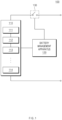
- FIG. 2 is a block diagram illustrating a configuration of a battery management apparatus, according to an embodiment disclosed herein.
- FIG. 3 is a view for generally describing a battery management apparatus according to an embodiment disclosed herein.
- the battery management apparatus 120 may include a first controller 121, a second controller 122, and a communication unit 123.
- the battery module 110 may include the plurality of battery cells 111, 112, 113, and 114, but the first battery cell 111will be described as an example below.
- the first controller 121 may obtain state data including a measurement value resulting from measuring the state of the first battery cell 111.
- the measurement value may include voltage, current, and temperature of the first battery cell 111 measured cumulatively.
- the state data may include the measurement value including the measured voltage, current, and temperature of the first battery cell 111 and a state of health (SOH) of the first battery cell 111 calculated based on the measurement value.
- SOH state of health
- the first controller 121 may obtain a measurement value resulting from measuring voltage, current, and temperature of the first battery cell 111 from time (t-N) to time (t-1), and obtain an SOH of the first battery cell 111 from the time (t-N) to the time (t-1) based on the measurement value.
- N may be defined as a constant value indicating a variation of a variable t indicating time.
- the first controller 121 may obtain a voltage V t-N , a current I t-N , and a temperature T t-N of the first battery cell 111 at the time (t-N) to obtain an SOH value of the first battery cell 111 at the time (t-N), and obtain a voltage V t- ( N- 1) , a current I t -( N -1) , and a temperature T t -( N -1) of the first battery cell 111 at time (t-(N-1)) to obtain an SOH value of the first battery cell 111 at the time (t-(N-1)). That is, the first controller 121 may obtain past state data of the first battery cell 111 from the time (t-N) to the time (t-1).
- the first controller 121 may obtain a measurement value of a current I t and a temperature T t of the first battery cell 111 measured at the current time t.
- the second controller 122 may apply at least a part of the state data to machine learning to generate prediction data for predicting the state of the first battery cell 111.
- the prediction data may include a voltage V' t of the first battery cell 111.
- the second controller 122 may predict the voltage of the first battery cell 111 by applying past data included in state data and current and temperature of the first battery cell 111 measured at the current time and included in the state data to a machine learning model of a time-series analysis structure.
- the time series may be defined as an order of arrangement at specific time intervals over time.
- the machine learning model of the time-series analysis structure may include a long short term memory (LSTM) algorithm.
- the LSTM algorithm which is one of artificial neural networks, may be defined as a structure in which a recurrent neural network (RNN) is modified to reflect a long term feature.
- the LSTM algorithm is mainly applied to problems of time-series data showing a change over time.
- the LSTM algorithm may predict (n+1)th data for measurement time-series data of an object having a length of n.
- the second controller 122 may predict the voltage V' t of the first battery cell 111 at the current time t by applying voltage, current, and temperature and SOH data of the first battery cell 111 from the time (t-N) to the time (t-1) and current data and temperature data of the first battery cell 111 measured at the current time t to the LSTM algorithm. That is, the second controller 122 may generate prediction data for predicting the voltage of the first battery cell 111 at the current time t by applying state data of the first battery cell 111 from the time (t-N) to the time (t-1) to the LSTM algorithm.
- the second controller 122 may determine the state of the first battery cell 111 by comparing the prediction data with the state data. More specifically, the second controller 122 may generate an anomaly score by applying the predicted voltage V' t of the first battery cell 111 at the time t and the measured voltage V t of the first battery cell 111 at the time t to an anomaly detection algorithm, thus to analyze an anomaly state of the battery.
- the anomaly detection algorithm may be defined as an artificial intelligence model that analyzes an anomaly score of an entity showing a pattern and a feature different from data prescribed as being normal.
- the second controller 122 may generate an anomaly score that is a difference between the predicted voltage V' t of the first battery cell 111 at the time t and the measured voltage V t of the first battery cell 111 at the time t.
- the second controller 122 may determine that the first battery cell 111 is in the anomaly state, when a rate of anomaly scores equal to or greater than a threshold value among anomaly scores generated for a predetermined time is equal to or greater than a specific rate. That is, when a rate of anomaly scores exceeding the threshold value among anomaly scores, generated for a predetermined time, corresponding to differences between the predicted voltages V' t of the first battery cell 111 and the measured voltages V t of the first battery cell 111, is maintained for several seconds to several tens of seconds, then the second controller 122 may determine the first battery cell 111 to be in the anomaly state.
- the second controller 122 may compress state data obtained for a predetermined time before and after when the first battery cell 111 is determined to be in the anomaly state.
- the communication unit 123 may transmit state data to a server 200 based on a result of determining, by the second controller 122, the state of the first battery cell 111. That is, when the first battery cell 111 is determined to be in the anomaly state, the communication unit 123 may transmit the compressed state data of the first battery cell 111 to the server 200 using an over-the-air (OTA) technique.
- OTA over-the-air
- the OTA technique which is one of firmware update schemes, may be defined as a technique for wirelessly updating firmware using Wireless Fidelity (Wi-Fi), etc., without connection to a computer.
- battery data is transmitted to the server, thereby improving diagnosis efficiency of the battery management apparatus 120 and preventing unnecessary power supply of the battery management apparatus 120.
- the battery management apparatus 120 and the battery testing system 1000 analyze first battery data by using a voltage prediction model designed in the battery management apparatus and transmit the battery data to a server having rich computing resources in the vent of detection of an anomaly phenomenon for precise analysis, thereby precisely analyzing the anomaly phenomenon of the battery and innovatively reducing data transmitted to the server, such that a communication resource may be reduced and storage and computing capabilities of a cloud computer included in the server may be lightened.
- the battery management apparatus 120 and the battery testing system 1000 may transmit necessary minimum battery data to the server without a data loss to reduce infrastructure investment cost and network cost of the server.
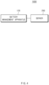
- FIG. 4 is a block diagram illustrating a configuration of a battery testing system according to an embodiment disclosed herein.
- FIG. 5 is a flowchart illustrating an operating method of a battery testing system according to an embodiment disclosed herein.
- FIGS. 4 and 5 a configuration and an operation of the battery testing system 1000 will be described.
- the battery testing system 1000 may include the battery management apparatus 120 and the server 200.
- the battery management apparatus 120 may be substantially the same as the battery management apparatus 120 described with reference to FIGS. 1 to 3 , and thus will be briefly described to avoid redundant description.
- the battery management apparatus 120 may obtain state data including a measurement value resulting from measuring the state of the first battery cell 111.
- the state data may include the measurement value including the measured voltage, current, and temperature of the first battery cell 111 and an SOH of the first battery cell 111 calculated based on the measurement value. That is, the battery management apparatus 120 may obtain past state data of the first battery cell 111 from the time (t-N) to the time (t-1). The battery management apparatus 120 may obtain a measurement value of a current and a temperature of the first battery cell 111 measured at the current time t.
- the battery management apparatus 120 may apply at least a part of the state data to machine learning to generate prediction data for predicting the state of the first battery cell 111.
- the battery management apparatus 120 may predict the voltage V' t of the first battery cell 111 at the current time t by applying voltage, current, and temperature and SOH data of the first battery cell 111 from the time (t-N) to the time (t-1) and current data and temperature data of the first battery cell 111 measured at the current time t to the LSTM algorithm.
- the battery management apparatus 120 may determine the state of the first battery cell 111 by comparing the prediction data with the state data. More specifically, the battery management apparatus 120 may generate an anomaly score by applying the predicted voltage V' t of the first battery cell 111 at the time t and the measured voltage V t of the first battery cell 111 at the time t to an anomaly detection algorithm, thus to analyze an anomaly state of the battery.
- the battery management apparatus 120 may determine that the first battery cell 111 is in the anomaly state, when a rate of anomaly scores equal to or greater than a threshold value among anomaly scores generated for a predetermined time is equal to or greater than a specific rate.
- the battery management apparatus 120 may compress state data obtained for a predetermined time before and after when the first battery cell 111 is determined to be in the anomaly state, and transmit the compressed state data to the server 200.
- the server 200 may be defined as a determining apparatus that receives the state data of the first battery cell 111 and determines whether the first battery cell 111 is defective.
- the server 200 may include, for example, a cloud computing technique.
- the server 200 may include an artificial intelligence model that extracts false alarm corresponding to a case where the first battery cell 111 is determined to be in the anomaly state based on the state data of the first battery cell 111 determined by the battery management apparatus 120 even though the first battery cell 111 is not actually in the anomaly state.
- the server 200 may receive the compressed state data transmitted from the battery management apparatus 120.
- the server 200 may analyze the compressed data received from the battery management apparatus 120, that is, the state data obtained for the predetermined time before and after the determination as the anomaly state to extract false alarm corresponding to the case where the first battery cell 111 is determined to be in the anomaly state even though the first battery cell 111 is not actually in the anomaly state.
- the server 200 may determine whether a frequency of the false alarm is equal to or greater than a threshold frequency.
- the server 200 may recalculate an SOH value of the first battery cell 111 included in the battery management apparatus 120 and reset a threshold value of an anomaly detection algorithm for transmission to the battery management apparatus 120.
- the server 200 may analyze a cause for occurrence of the false alarm of the first battery cell 111 as the SOH value of the first battery cell 111 and the threshold value of the anomaly detection algorithm, input to the LSTM algorithm of the battery management apparatus 120.
- the LSTM algorithm of the battery management apparatus 120 may receive, as past data included in the state data of the first battery cell 111, a measurement value resulting from measuring voltage, current, and temperature of the first battery cell 111 and an SOH value of the first battery cell 111 based on the measurement value.
- a measurement value resulting from measuring voltage, current, and temperature of the first battery cell 111 and an SOH value of the first battery cell 111 based on the measurement value.
- an error may occur in the LSTM algorithm and this error may cause false alarm of the battery testing system 1000.
- the server 200 may recalculate the SOH value of the first battery cell 111 input to the battery management apparatus 120 and transmit the recalculated SOH value to the battery management apparatus 120.
- the server 200 may analyze a cause for occurrence of the false alarm of the first battery cell 111 as the threshold value of the anomaly detection algorithm of the battery management apparatus 120.
- the battery management apparatus 120 may generate an anomaly score that is a difference between the predicted voltage V' t of the first battery cell 111 at the time t and the measured voltage V t of the first battery cell 111 at the time t by using the anomaly detection algorithm, and determine the first battery cell 111 to be in the anomaly state when a rate of anomaly scores greater than a threshold value among generated anomaly scores is greater than a specific rate.
- the server 200 may reset the threshold value of the anomaly detection algorithm input to the battery management apparatus 120 and transmit the reset threshold value to the battery management apparatus 120.
- the battery management apparatus 120 may update the LSTM algorithm and the anomaly detection algorithm.
Landscapes
- Engineering & Computer Science (AREA)
- Physics & Mathematics (AREA)
- General Physics & Mathematics (AREA)
- Theoretical Computer Science (AREA)
- Software Systems (AREA)
- Computing Systems (AREA)
- Evolutionary Computation (AREA)
- Data Mining & Analysis (AREA)
- Mathematical Physics (AREA)
- General Engineering & Computer Science (AREA)
- Artificial Intelligence (AREA)
- Computer Vision & Pattern Recognition (AREA)
- Medical Informatics (AREA)
- Life Sciences & Earth Sciences (AREA)
- General Chemical & Material Sciences (AREA)
- Electrochemistry (AREA)
- Chemical Kinetics & Catalysis (AREA)
- Chemical & Material Sciences (AREA)
- Manufacturing & Machinery (AREA)
- General Health & Medical Sciences (AREA)
- Molecular Biology (AREA)
- Computational Linguistics (AREA)
- Biophysics (AREA)
- Biomedical Technology (AREA)
- Sustainable Development (AREA)
- Sustainable Energy (AREA)
- Power Engineering (AREA)
- Transportation (AREA)
- Mechanical Engineering (AREA)
- Health & Medical Sciences (AREA)
- Microelectronics & Electronic Packaging (AREA)
- Secondary Cells (AREA)
- Tests Of Electric Status Of Batteries (AREA)
- Charge And Discharge Circuits For Batteries Or The Like (AREA)
Abstract
Description
- This application claims priority to and the benefit of
Korean Patent Application No. 10-2021-0107250 filed in the Korean Intellectual Property Office on August 13, 2021 - Embodiments disclosed herein relate to a battery management apparatus and a battery testing system including the same.
- An electric vehicle is supplied with electricity from outside to charge a battery, and then a motor is driven by a voltage charged in the battery to obtain power. The battery of the electric vehicle may have heat generated therein by chemical reaction occurring in a process of charging and discharging electricity, and the heat may impair performance and lifetime of the battery. Thus, a battery management apparatus (or a battery management system (BMS)) that monitors temperature, voltage, and current of the battery is driven to diagnose the state of the battery.
- However, when high-performance GPU or NPU is mounted on the battery management apparatus to precisely analyze the state of the battery in real time, the efficiency of the battery management apparatus is degraded and the cost of the battery management apparatus increases. Moreover, when the entire battery data measured by the battery management apparatus is transmitted to a cloud server for analysis, infra installation cost and communication cost incur and efficiency is degraded in a process of managing and analyzing a lot of data.
- Embodiments disclosed herein aim to provide a battery management apparatus and a battery testing system including the same, in which only data of a battery determined to be in an anomaly situation is precisely analyzed, thereby improving the efficiency of the battery management apparatus and reducing infra installation cost and communication cost.
- Technical problems of the embodiments disclosed herein are not limited to the above-described technical problems, and other unmentioned technical problems would be clearly understood by one of ordinary skill in the art from the following description.
- A battery management apparatus according to an embodiment disclosed herein includes a first controller configured to obtain state data including a measurement value resulting from measuring a state of a battery, a second controller configured to generate prediction data for predicting the state of the battery by applying at least a part of the state data to machine learning and to determine the state of the battery by comparing the prediction data with the state data of the battery, and a communication unit configured to transmit the state data to a server based on a result of determining the state of the battery.
- According to an embodiment, the second controller may be further configured to compress the state data obtained for a predetermined time before and after when the battery is determined to be in an anomaly state, in case that the battery is determined to be in the anomaly state.
- According to an embodiment, the communication unit may be further configured to transmit the compressed state data of the battery to the server.
- According to an embodiment, the measurement value may include voltage, current, and temperature of the battery, which are measured cumulatively, and the state data may include the measurement value and a state of health (SOH) of the battery, calculated based on the measurement value.
- According to an embodiment, the prediction data may include a voltage of the battery, and the second controller may be further configured to predict the voltage of the battery by applying past data included in the state data and current and temperature of the battery, which are included in the state data and measured at current time, to the machine learning model.
- According to an embodiment, the second controller may be further configured to predict the voltage of the battery by applying the state data to a long short term memory (LSTM) algorithm.
- According to an embodiment, the second controller may be further configured to generate an anomaly score by applying the state data and the prediction data to an anomaly detection algorithm.
- According to an embodiment, the second controller may be further configured to determine the battery to be in the anomaly state when a rate of anomaly scores equal to or greater than a threshold value among anomaly values generated for a predetermined time is equal to or greater than a specific rate.
- A battery testing system according to an embodiment disclosed herein includes a battery management apparatus configured to generate prediction data for predicting a state of a battery by applying at least a part of state data including a measurement value resulting from measuring the state of the battery to machine learning, to determine the state of the battery by comparing the prediction data with state data of the battery, and to transmit the state data to a server based on a result of determining the state of the battery and a server configured to determine whether the battery is in an anomaly state, based on the state data of the battery.
- According to an embodiment, the battery management apparatus may be further configured to compress the state data obtained for a predetermined time before and after when the battery is determined to be in an anomaly state, and to transmit the compressed state data to the server, in case that the battery is determined to be in the anomaly state.
- According to an embodiment, the measurement value may include voltage, current, and temperature of the battery, which are measured cumulatively, and the state data may include the measurement value and an SOH of the battery, calculated based on the measurement value.
- According to an embodiment, the battery management apparatus may be further configured to predict the voltage of the battery by applying past data included in the state data and current and temperature of the battery, which are included in the state data and measured at current time, to an LSTM algorithm.
- According to an embodiment, the battery management apparatus may be further configured to generate an anomaly score by applying the state data and the prediction data to an anomaly detection algorithm, and to determine the battery to be in the anomaly state when a rate of anomaly scores equal to or greater than a threshold value among anomaly values generated for a predetermined time is equal to or greater than a specific rate.
- According to an embodiment, the server may be further configured to extract false alarm when the battery is determined to be in the anomaly state in the battery management apparatus even though the battery is not actually in the anomaly state.
- According to an embodiment, the server may be further configured to measure the SOH value of the battery and the threshold value of the anomaly detection algorithm and to transmit the SOH value and the threshold value to the battery management apparatus, when a frequency of the false alarm is equal to or greater than a threshold frequency.
- According to an embodiment, the battery management apparatus may be further configured to update the LSTM algorithm and the anomaly detection algorithm based on the SOH value and the threshold value, received from the server.
- With a battery management apparatus and a battery testing system including the same according to an embodiment disclosed herein, only data of a battery determined to be in an anomaly situation may be precisely analyzed to improve the efficiency of the battery management apparatus and reduce infra installation cost and communication cost.
-
-
FIG. 1 illustrates a configuration of a battery pack according to an embodiment disclosed herein. -
FIG. 2 is a block diagram illustrating a configuration of a battery management apparatus, according to an embodiment disclosed herein. -
FIG. 3 is a view for generally describing a battery management apparatus according to an embodiment disclosed herein. -
FIG. 4 is a block diagram illustrating a configuration of a battery testing system according to an embodiment disclosed herein. -
FIG. 5 is a flowchart illustrating an operating method of a battery testing system according to an embodiment disclosed herein. - Hereinafter, some embodiments disclosed in this document will be described in detail with reference to the exemplary drawings. In adding reference numerals to components of each drawing, it should be noted that the same components are given the same reference numerals even though they are indicated in different drawings. In addition, in describing the embodiments disclosed in this document, when it is determined that a detailed description of a related known configuration or function interferes with the understanding of an embodiment disclosed in this document, the detailed description thereof will be omitted.
- To describe a component of an embodiment disclosed herein, terms such as first, second, A, B, (a), (b), etc., may be used. These terms are used merely for distinguishing one component from another component and do not limit the component to the essence, sequence, order, etc., of the component. The terms used herein, including technical and scientific terms, have the same meanings as terms that are generally understood by those skilled in the art, as long as the terms are not differently defined. Generally, the terms defined in a generally used dictionary should be interpreted as having the same meanings as the contextual meanings of the relevant technology and should not be interpreted as having ideal or exaggerated meanings unless they are clearly defined in the present document.
-
FIG. 1 illustrates a battery pack according to an embodiment disclosed herein. - Referring to
FIG. 1 , abattery pack 100 according to an embodiment disclosed herein may include abattery module 110, abattery management apparatus 120, and arelay 130. - The
battery module 110 may include afirst battery cell 111, asecond battery cell 112, athird battery cell 113, and afourth battery cell 114. Although the plurality of battery cells are illustrated as four inFIG. 1 , the present invention is not limited thereto, and thebattery module 110 may include n battery cells (n is a natural number equal to or greater than 2). - The
battery module 110 may supply power to a target device (not shown). To this end, thebattery module 110 may be electrically connected to the target device. Herein, the target device may include an electrical, electronic, or mechanical device that operates by receiving power from thebattery pack 100 including the plurality ofbattery cells - The
battery cell 111 may be a lithium ion (Li-ion) battery, an Li-ion polymer battery, a nickel-cadmium (Ni-Cd) battery, a nickel hydrogen (Ni-MH) battery, etc., and may not be limited thereto. Meanwhile, although onebattery module 110 is illustrated inFIG. 1 , thebattery module 110 may be configured in plural according to an embodiment. - The battery management apparatus (or a battery management system (BMS)) 120 may manage and/or control a state and/or an operation of the
battery module 110. For example, thebattery management apparatus 120 may manage and/or control the states and/or operations of the plurality ofbattery cells battery module 110. Thebattery management apparatus 120 may manage charging and/or discharging of thebattery module 110. - In addition, the
battery management apparatus 120 may monitor a voltage, a current, a temperature, etc., of thebattery module 110 and/or each of the plurality ofbattery cells battery module 110. A sensor or various measurement modules for monitoring performed by thebattery management apparatus 120, which are not shown, may be additionally installed in thebattery module 110, a charging/discharging path, any position of thebattery module 110, etc. Thebattery management apparatus 120 may calculate a parameter indicating a state of thebattery module 110, e.g., a state of charge (SOC), a state of health (SOH) etc., based on a measurement value such as monitored voltage, current, temperature, etc. - The
battery management apparatus 120 may control an operation of therelay 130. For example, thebattery management apparatus 120 may short-circuit therelay 130 to supply power to the target device. Thebattery management apparatus 120 may short-circuit therelay 130 when a charging device is connected to thebattery pack 100. - The
battery management apparatus 120 may calculate a cell balancing time of each of the plurality ofbattery cells battery management apparatus 120 may calculate a cell balancing time based on an SOC, a battery capacity, and a balancing efficiency of each of the plurality ofbattery cells - Hereinbelow, referring to
FIGS. 2 and3 , a configuration and an operating method thebattery management apparatus 120 will be described. -
FIG. 2 is a block diagram illustrating a configuration of a battery management apparatus, according to an embodiment disclosed herein.FIG. 3 is a view for generally describing a battery management apparatus according to an embodiment disclosed herein. - Referring to
FIG. 2 , thebattery management apparatus 120 may include afirst controller 121, asecond controller 122, and acommunication unit 123. - In
FIG. 2 , thebattery module 110 may include the plurality ofbattery cells - Referring to
FIG. 3 , thefirst controller 121 may obtain state data including a measurement value resulting from measuring the state of thefirst battery cell 111. Herein, the measurement value may include voltage, current, and temperature of thefirst battery cell 111 measured cumulatively. For example, the state data may include the measurement value including the measured voltage, current, and temperature of thefirst battery cell 111 and a state of health (SOH) of thefirst battery cell 111 calculated based on the measurement value. - For example, the
first controller 121 may obtain a measurement value resulting from measuring voltage, current, and temperature of thefirst battery cell 111 from time (t-N) to time (t-1), and obtain an SOH of thefirst battery cell 111 from the time (t-N) to the time (t-1) based on the measurement value. Herein, N may be defined as a constant value indicating a variation of a variable t indicating time. - For example, the
first controller 121 may obtain a voltage Vt-N , a current It-N , and a temperature Tt-N of thefirst battery cell 111 at the time (t-N) to obtain an SOH value of thefirst battery cell 111 at the time (t-N), and obtain a voltage V t-(N-1), a current I t-(N-1), and a temperature T t-(N-1) of thefirst battery cell 111 at time (t-(N-1)) to obtain an SOH value of thefirst battery cell 111 at the time (t-(N-1)). That is, thefirst controller 121 may obtain past state data of thefirst battery cell 111 from the time (t-N) to the time (t-1). - The
first controller 121 may obtain a measurement value of a current It and a temperature Tt of thefirst battery cell 111 measured at the current time t. - The
second controller 122 may apply at least a part of the state data to machine learning to generate prediction data for predicting the state of thefirst battery cell 111. Herein, the prediction data may include a voltage V't of thefirst battery cell 111. - More specifically, the
second controller 122 may predict the voltage of thefirst battery cell 111 by applying past data included in state data and current and temperature of thefirst battery cell 111 measured at the current time and included in the state data to a machine learning model of a time-series analysis structure. The time series may be defined as an order of arrangement at specific time intervals over time. The machine learning model of the time-series analysis structure may include a long short term memory (LSTM) algorithm. The LSTM algorithm, which is one of artificial neural networks, may be defined as a structure in which a recurrent neural network (RNN) is modified to reflect a long term feature. The LSTM algorithm is mainly applied to problems of time-series data showing a change over time. The LSTM algorithm may predict (n+1)th data for measurement time-series data of an object having a length of n. - The
second controller 122 may predict the voltage V't of thefirst battery cell 111 at the current time t by applying voltage, current, and temperature and SOH data of thefirst battery cell 111 from the time (t-N) to the time (t-1) and current data and temperature data of thefirst battery cell 111 measured at the current time t to the LSTM algorithm. That is, thesecond controller 122 may generate prediction data for predicting the voltage of thefirst battery cell 111 at the current time t by applying state data of thefirst battery cell 111 from the time (t-N) to the time (t-1) to the LSTM algorithm. - The
second controller 122 may determine the state of thefirst battery cell 111 by comparing the prediction data with the state data. More specifically, thesecond controller 122 may generate an anomaly score by applying the predicted voltage V't of thefirst battery cell 111 at the time t and the measured voltage Vt of thefirst battery cell 111 at the time t to an anomaly detection algorithm, thus to analyze an anomaly state of the battery. Herein, the anomaly detection algorithm may be defined as an artificial intelligence model that analyzes an anomaly score of an entity showing a pattern and a feature different from data prescribed as being normal. - That is, the
second controller 122 may generate an anomaly score that is a difference between the predicted voltage V't of thefirst battery cell 111 at the time t and the measured voltage Vt of thefirst battery cell 111 at the time t. - The
second controller 122 may determine that thefirst battery cell 111 is in the anomaly state, when a rate of anomaly scores equal to or greater than a threshold value among anomaly scores generated for a predetermined time is equal to or greater than a specific rate. That is, when a rate of anomaly scores exceeding the threshold value among anomaly scores, generated for a predetermined time, corresponding to differences between the predicted voltages V't of thefirst battery cell 111 and the measured voltages Vt of thefirst battery cell 111, is maintained for several seconds to several tens of seconds, then thesecond controller 122 may determine thefirst battery cell 111 to be in the anomaly state. - When the
first battery cell 111 is determined to be in the anomaly state, thesecond controller 122 may compress state data obtained for a predetermined time before and after when thefirst battery cell 111 is determined to be in the anomaly state. - The
communication unit 123 may transmit state data to aserver 200 based on a result of determining, by thesecond controller 122, the state of thefirst battery cell 111. That is, when thefirst battery cell 111 is determined to be in the anomaly state, thecommunication unit 123 may transmit the compressed state data of thefirst battery cell 111 to theserver 200 using an over-the-air (OTA) technique. Herein, the OTA technique, which is one of firmware update schemes, may be defined as a technique for wirelessly updating firmware using Wireless Fidelity (Wi-Fi), etc., without connection to a computer. - As such, with the
battery management apparatus 120 and abattery testing system 1000 according to an embodiment disclosed herein, when the battery is determined to be in the anomaly state, battery data is transmitted to the server, thereby improving diagnosis efficiency of thebattery management apparatus 120 and preventing unnecessary power supply of thebattery management apparatus 120. - The
battery management apparatus 120 and thebattery testing system 1000 analyze first battery data by using a voltage prediction model designed in the battery management apparatus and transmit the battery data to a server having rich computing resources in the vent of detection of an anomaly phenomenon for precise analysis, thereby precisely analyzing the anomaly phenomenon of the battery and innovatively reducing data transmitted to the server, such that a communication resource may be reduced and storage and computing capabilities of a cloud computer included in the server may be lightened. - The
battery management apparatus 120 and thebattery testing system 1000 may transmit necessary minimum battery data to the server without a data loss to reduce infrastructure investment cost and network cost of the server. -
FIG. 4 is a block diagram illustrating a configuration of a battery testing system according to an embodiment disclosed herein.FIG. 5 is a flowchart illustrating an operating method of a battery testing system according to an embodiment disclosed herein. - Hereinbelow, referring to
FIGS. 4 and5 , a configuration and an operation of thebattery testing system 1000 will be described. - Referring to
FIG. 4 , thebattery testing system 1000 according to an embodiment disclosed herein may include thebattery management apparatus 120 and theserver 200. - The
battery management apparatus 120 may be substantially the same as thebattery management apparatus 120 described with reference toFIGS. 1 to 3 , and thus will be briefly described to avoid redundant description. - Referring to
FIG. 5 , an operating method of a battery testing system operation S101 of obtaining, by the battery management apparatus 120, state data including a measurement value resulting from measuring the state of the first battery cell 111, operation S102 of generating, by the battery management apparatus 120, prediction data by applying the state data to an LSTM algorithm, operation S103 of determining, by the battery management apparatus 120, the state of the first battery cell 111 by inputting the prediction data and the state data to an anomaly detection algorithm, operation S104 of determining, by the battery management apparatus 120, whether the first battery cell 111 is in an anomaly state, operation S105 of transmitting, by the battery management apparatus 120, the state data of the first battery cell 111 when the first battery cell 111 is in the anomaly state, operation S106 of extracting, by the server 200, false alarm, operation S107 of determining, by the server 200, whether a frequency of the false alarm is equal to or greater than a threshold frequency, operation S108 of measuring, by the server 200, an SOH value of the first battery cell 111 and the threshold value of the anomaly detection algorithm and transmitting the SOH and the threshold value to the battery management apparatus 120 when the frequency of the false alarm is equal to or greater than the threshold frequency, and operation S109 of applying, by the battery management apparatus 120, the SOH value and the threshold value received from the server 200 to the LSTM algorithm and the anomaly detection algorithm. - Hereinbelow, operations S101 through S109 will be described in detail.
- In operation S101, the
battery management apparatus 120 may obtain state data including a measurement value resulting from measuring the state of thefirst battery cell 111. Herein, the state data may include the measurement value including the measured voltage, current, and temperature of thefirst battery cell 111 and an SOH of thefirst battery cell 111 calculated based on the measurement value. That is, thebattery management apparatus 120 may obtain past state data of thefirst battery cell 111 from the time (t-N) to the time (t-1). Thebattery management apparatus 120 may obtain a measurement value of a current and a temperature of thefirst battery cell 111 measured at the current time t. - In operation S101, the
battery management apparatus 120 may apply at least a part of the state data to machine learning to generate prediction data for predicting the state of thefirst battery cell 111. - For example, in operation S101, the
battery management apparatus 120 may predict the voltage V't of thefirst battery cell 111 at the current time t by applying voltage, current, and temperature and SOH data of thefirst battery cell 111 from the time (t-N) to the time (t-1) and current data and temperature data of thefirst battery cell 111 measured at the current time t to the LSTM algorithm. - In operation S103, the
battery management apparatus 120 may determine the state of thefirst battery cell 111 by comparing the prediction data with the state data. More specifically, thebattery management apparatus 120 may generate an anomaly score by applying the predicted voltage V't of thefirst battery cell 111 at the time t and the measured voltage Vt of thefirst battery cell 111 at the time t to an anomaly detection algorithm, thus to analyze an anomaly state of the battery. - In operation S104, the
battery management apparatus 120 may determine that thefirst battery cell 111 is in the anomaly state, when a rate of anomaly scores equal to or greater than a threshold value among anomaly scores generated for a predetermined time is equal to or greater than a specific rate. - In operation S105, when the
first battery cell 111 is determined to be in the anomaly state, thebattery management apparatus 120 may compress state data obtained for a predetermined time before and after when thefirst battery cell 111 is determined to be in the anomaly state, and transmit the compressed state data to theserver 200. - The
server 200 may be defined as a determining apparatus that receives the state data of thefirst battery cell 111 and determines whether thefirst battery cell 111 is defective. Theserver 200 may include, for example, a cloud computing technique. - The
server 200 may include an artificial intelligence model that extracts false alarm corresponding to a case where thefirst battery cell 111 is determined to be in the anomaly state based on the state data of thefirst battery cell 111 determined by thebattery management apparatus 120 even though thefirst battery cell 111 is not actually in the anomaly state. - In operation S106, when the
battery management apparatus 120 compresses the state data of thefirst battery cell 111 obtained for a predetermined time before and after when thebattery management apparatus 120 is determined in the anomaly state, and transmits the compressed state data to theserver 200, theserver 200 may receive the compressed state data transmitted from thebattery management apparatus 120. - In operation S106, the
server 200 may analyze the compressed data received from thebattery management apparatus 120, that is, the state data obtained for the predetermined time before and after the determination as the anomaly state to extract false alarm corresponding to the case where thefirst battery cell 111 is determined to be in the anomaly state even though thefirst battery cell 111 is not actually in the anomaly state. - In operation S107, the
server 200 may determine whether a frequency of the false alarm is equal to or greater than a threshold frequency. - In operation S108, when the frequency of the false alarm is equal to or greater than the threshold frequency, the
server 200 may recalculate an SOH value of thefirst battery cell 111 included in thebattery management apparatus 120 and reset a threshold value of an anomaly detection algorithm for transmission to thebattery management apparatus 120. - That is, in operation S108, the
server 200 may analyze a cause for occurrence of the false alarm of thefirst battery cell 111 as the SOH value of thefirst battery cell 111 and the threshold value of the anomaly detection algorithm, input to the LSTM algorithm of thebattery management apparatus 120. - The LSTM algorithm of the
battery management apparatus 120 may receive, as past data included in the state data of thefirst battery cell 111, a measurement value resulting from measuring voltage, current, and temperature of thefirst battery cell 111 and an SOH value of thefirst battery cell 111 based on the measurement value. Thus, when an error occurs in a process of calculating, by thebattery management apparatus 120, the voltage, current, and temperature of thefirst battery cell 111 and the SOH value of thefirst battery cell 111, an error may occur in the LSTM algorithm and this error may cause false alarm of thebattery testing system 1000. Thus, theserver 200 may recalculate the SOH value of thefirst battery cell 111 input to thebattery management apparatus 120 and transmit the recalculated SOH value to thebattery management apparatus 120. - In operation S108, the
server 200 may analyze a cause for occurrence of the false alarm of thefirst battery cell 111 as the threshold value of the anomaly detection algorithm of thebattery management apparatus 120. - The
battery management apparatus 120 may generate an anomaly score that is a difference between the predicted voltage V't of thefirst battery cell 111 at the time t and the measured voltage Vt of thefirst battery cell 111 at the time t by using the anomaly detection algorithm, and determine thefirst battery cell 111 to be in the anomaly state when a rate of anomaly scores greater than a threshold value among generated anomaly scores is greater than a specific rate. Thus, when the threshold value for determining, by thebattery management apparatus 120, the anomaly score as an abnormal value is not appropriate, an error may occur for thebattery management apparatus 120 to determine the anomaly state of thefirst battery cell 111, and this error may cause false alarm of thebattery testing system 1000. Thus, theserver 200 may reset the threshold value of the anomaly detection algorithm input to thebattery management apparatus 120 and transmit the reset threshold value to thebattery management apparatus 120. - In operation S109, when the
battery management apparatus 120 receives the SOH value of thefirst battery cell 111 and the threshold value of the anomaly detection algorithm from theserver 200, thebattery management apparatus 120 may update the LSTM algorithm and the anomaly detection algorithm. - The above description is merely illustrative of the technical idea of the present disclosure, and various modifications and variations will be possible without departing from the essential characteristics of the present disclosure by those of ordinary skill in the art to which the present disclosure pertains.
- Therefore, the embodiments disclosed in the present invention are intended for description rather than limitation of the technical spirit of the present disclosure and the scope of the technical spirit of the present invention is not limited by these embodiments. The protection scope of the present invention should be interpreted by the following claims, and all technical spirits within the same range should be understood to be included in the range of the present invention.
Claims (16)
- A battery management apparatus comprising:a first controller configured to obtain state data comprising a measurement value resulting from measuring a state of a battery;a second controller configured to generate prediction data for predicting the state of the battery by applying at least a part of the state data to machine learning and to determine the state of the battery by comparing the prediction data with the state data of the battery; anda communication unit configured to transmit the state data to a server based on a result of determining the state of the battery.
- The battery management apparatus of claim 1, wherein the second controller is further configured to compress the state data obtained for a predetermined time before and after when the battery is determined to be in an anomaly state, in case that the battery is determined to be in the anomaly state.
- The battery management apparatus of claim 2, wherein the communication unit is further configured to transmit the compressed state data of the battery to the server.
- The battery management apparatus of claim 1, wherein the measurement value comprises voltage, current, and temperature of the battery, which are measured cumulatively, and the state data comprises the measurement value and a state of health (SOH) of the battery, calculated based on the measurement value.
- The battery management apparatus of claim 4, wherein the prediction data comprises a voltage of the battery, and
the second controller is further configured to predict the voltage of the battery by applying past data included in the state data and current and temperature of the battery, which are included in the state data and measured at current time, to a machine learning model. - The battery management apparatus of claim 5, wherein the second controller is further configured to predict the voltage of the battery by applying the state data to a long short term memory (LSTM) algorithm.
- The battery management apparatus of claim 4, wherein the second controller is further configured to generate an anomaly score by applying the state data and the prediction data to an anomaly detection algorithm.
- The battery management apparatus of claim 7, wherein the second controller is further configured to determine the battery to be in the anomaly state when a rate of anomaly scores equal to or greater than a threshold value among anomaly values generated for a predetermined time is equal to or greater than a specific rate.
- A battery testing system comprising:a battery management apparatus configured to generate prediction data for predicting a state of a battery by applying at least a part of state data comprising a measurement value resulting from measuring the state of the battery to machine learning, to determine the state of the battery by comparing the prediction data with state data of the battery, and to transmit the state data to a server based on a result of determining the state of the battery; anda server configured to determine whether the battery is in an anomaly state, based on the state data of the battery.
- The battery testing system of claim 9, wherein the battery management apparatus is further configured to compress the state data obtained for a predetermined time before and after when the battery is determined to be in an anomaly state, and to transmit the compressed state data to the server, in case that the battery is determined to be in the anomaly state.
- The battery testing system of claim 9, wherein the measurement value comprises voltage, current, and temperature of the battery, which are measured cumulatively, and the state data comprises the measurement value and a state of health (SOH) of the battery, calculated based on the measurement value.
- The battery testing system of claim 11, wherein the battery management apparatus is further configured to predict the voltage of the battery by applying past data included in the state data and current and temperature of the battery, which are included in the state data and measured at current time, to a long short term memory (LSTM) algorithm.
- The battery testing system of claim 11, wherein the battery management apparatus is further configured to generate an anomaly score by applying the state data and the prediction data to an anomaly detection algorithm, and to determine the battery to be in the anomaly state when a rate of anomaly scores equal to or greater than a threshold value among anomaly values generated for a predetermined time is equal to or greater than a specific rate.
- The battery testing system of claim 13, wherein the server is further configured to extract false alarm when the battery is determined to be in the anomaly state in the battery management apparatus even though the battery is not actually in the anomaly state.
- The battery testing system of claim 14, wherein the server is further configured to measure the SOH value of the battery and the threshold value of the anomaly detection algorithm and to transmit the SOH value and the threshold value to the battery management apparatus, when a frequency of the false alarm is equal to or greater than a threshold frequency.
- The battery testing system of claim 15, wherein the battery management apparatus is further configured to update the LSTM algorithm and the anomaly detection algorithm based on the SOH value and the threshold value, received from the server.
Applications Claiming Priority (2)
| Application Number | Priority Date | Filing Date | Title |
|---|---|---|---|
| KR1020210107250A KR102874967B1 (en) | 2021-08-13 | 2021-08-13 | Apparatus for managing battery and battery inspection system comprising the same |
| PCT/KR2022/011061 WO2023018070A1 (en) | 2021-08-13 | 2022-07-27 | Battery management apparatus and battery inspection system including same |
Publications (2)
| Publication Number | Publication Date |
|---|---|
| EP4386401A1 true EP4386401A1 (en) | 2024-06-19 |
| EP4386401A4 EP4386401A4 (en) | 2024-12-18 |
Family
ID=85200252
Family Applications (1)
| Application Number | Title | Priority Date | Filing Date |
|---|---|---|---|
| EP22856069.4A Pending EP4386401A4 (en) | 2021-08-13 | 2022-07-27 | BATTERY MANAGEMENT DEVICE AND BATTERY INSPECTION SYSTEM COMPRISING SAME |
Country Status (6)
| Country | Link |
|---|---|
| US (1) | US20240241180A1 (en) |
| EP (1) | EP4386401A4 (en) |
| JP (1) | JP7658464B2 (en) |
| KR (1) | KR102874967B1 (en) |
| CN (1) | CN117396767A (en) |
| WO (1) | WO2023018070A1 (en) |
Families Citing this family (4)
| Publication number | Priority date | Publication date | Assignee | Title |
|---|---|---|---|---|
| US12466289B2 (en) * | 2023-04-12 | 2025-11-11 | Element Energy, Inc. | Artificial intelligence and machine learning architecture in a battery system |
| EP4703749A1 (en) * | 2024-08-29 | 2026-03-04 | The Penn State Research Foundation | Battery state of health estimation using onboard and remote battery monitor apparatus |
| WO2026079714A1 (en) * | 2024-10-08 | 2026-04-16 | 주식회사 엘지에너지솔루션 | Apparatus and method for managing battery |
| KR102813895B1 (en) * | 2024-11-15 | 2025-05-29 | 한국전자기술연구원 | Battery protection system and method based on multifaceted safety indicators |
Family Cites Families (21)
| Publication number | Priority date | Publication date | Assignee | Title |
|---|---|---|---|---|
| JP2002165372A (en) | 2000-11-27 | 2002-06-07 | Canon Inc | Wireless communication device |
| JP6370902B2 (en) | 2014-06-24 | 2018-08-15 | 株式会社東芝 | Deterioration control apparatus and method for storage battery system |
| KR102221756B1 (en) * | 2014-07-18 | 2021-03-02 | 삼성전자주식회사 | Method and apparatus for estimating state of battery |
| JP2018169161A (en) | 2015-08-31 | 2018-11-01 | 日立化成株式会社 | Deterioration diagnosis apparatus, deterioration diagnosis method, and deterioration diagnosis system for battery |
| US10191116B2 (en) * | 2015-10-15 | 2019-01-29 | Johnson Controls Technology Company | Battery test system for predicting battery test results |
| KR102726191B1 (en) | 2016-10-05 | 2024-11-06 | 삼성전자주식회사 | Device and method to estimate state of battery |
| CN107202959B (en) * | 2017-05-19 | 2019-11-05 | 江苏大学 | One kind being used for battery pack and battery management system matching test centring system |
| KR102239040B1 (en) * | 2018-06-29 | 2021-04-13 | 성균관대학교산학협력단 | Prognostics and health management systems for component of vehicle and methods thereof |
| CN108879875A (en) * | 2018-08-07 | 2018-11-23 | 宁波智果科技咨询服务有限公司 | A kind of charging pile system of battery charge state charge control |
| KR102106775B1 (en) * | 2018-08-14 | 2020-05-06 | 오토시맨틱스 주식회사 | Diagnosis method of battery using Deep Learning |
| KR102733072B1 (en) * | 2018-11-20 | 2024-11-20 | 주식회사 엘지에너지솔루션 | Apparatus and method for diagnosing battery abnormality, and battery pack including the apparatus |
| JP7310137B2 (en) | 2018-12-28 | 2023-07-19 | 株式会社Gsユアサ | DATA PROCESSING APPARATUS, DATA PROCESSING METHOD, AND COMPUTER PROGRAM |
| KR102354112B1 (en) * | 2019-03-26 | 2022-01-24 | 서강대학교산학협력단 | Apparatus and method for estimating status of battery based on artificial intelligence |
| KR20210024962A (en) * | 2019-08-26 | 2021-03-08 | 오토시맨틱스 주식회사 | Method and Apparatus for Diagnosis and Life Assessment for ESS Battery |
| JP7225421B2 (en) | 2019-09-10 | 2023-02-20 | 株式会社東芝 | Storage battery management system |
| US12392843B2 (en) * | 2019-09-25 | 2025-08-19 | Exicom Tele-Systems Limited | System and method for managing a battery pack |
| EP3826102A1 (en) * | 2019-11-20 | 2021-05-26 | Vestas Wind Systems A/S | Model based monitoring of battery system |
| JP7082603B2 (en) | 2019-12-25 | 2022-06-08 | 本田技研工業株式会社 | Machine learning device, machine learning method, charge rate estimation device, and charge rate estimation system |
| CN112051511A (en) * | 2020-08-26 | 2020-12-08 | 华中科技大学 | Method and system for estimating state of health of power battery based on multi-channel technology |
| KR102458165B1 (en) * | 2020-09-16 | 2022-10-25 | 일본전산리드코리아 주식회사 | Jig for PCB inspection |
| CN112924887B (en) * | 2021-01-27 | 2024-06-07 | 江西江铃集团新能源汽车有限公司 | Battery pack health detection method and device, readable storage medium and electronic equipment |
-
2021
- 2021-08-13 KR KR1020210107250A patent/KR102874967B1/en active Active
-
2022
- 2022-07-27 EP EP22856069.4A patent/EP4386401A4/en active Pending
- 2022-07-27 CN CN202280036595.9A patent/CN117396767A/en active Pending
- 2022-07-27 WO PCT/KR2022/011061 patent/WO2023018070A1/en not_active Ceased
- 2022-07-27 US US18/290,263 patent/US20240241180A1/en active Pending
- 2022-07-27 JP JP2023569629A patent/JP7658464B2/en active Active
Also Published As
| Publication number | Publication date |
|---|---|
| JP7658464B2 (en) | 2025-04-08 |
| US20240241180A1 (en) | 2024-07-18 |
| JP2024519755A (en) | 2024-05-21 |
| KR102874967B1 (en) | 2025-10-22 |
| EP4386401A4 (en) | 2024-12-18 |
| KR20230025130A (en) | 2023-02-21 |
| WO2023018070A1 (en) | 2023-02-16 |
| CN117396767A (en) | 2024-01-12 |
Similar Documents
| Publication | Publication Date | Title |
|---|---|---|
| EP4386401A1 (en) | Battery management apparatus and battery inspection system including same | |
| Chen et al. | A novel data-driven method for mining battery open-circuit voltage characterization | |
| US20230275276A1 (en) | Slave BMS Inspection System and Method | |
| KR20210141211A (en) | Apparatus and method for diagnosing battery | |
| US20240283039A1 (en) | Battery Testing Apparatus And Battery Testing System | |
| KR102914732B1 (en) | Apparatus for predicting capacity of battery and operating method of the same | |
| EP4451418A1 (en) | Battery management device and operation method thereof | |
| US20220166075A1 (en) | Method for Enhancing a Battery Module Model of a Battery Module Type | |
| US20260072087A1 (en) | Battery state prediction apparatus and operating method thereof | |
| KR102886638B1 (en) | Apparatus for estimating state of health of battery and operating method of the same | |
| KR20250111280A (en) | Apparatus for managing battery data and operating method of the same | |
| EP4660652A1 (en) | Battery data management device and operation method therefor | |
| EP4675291A1 (en) | Battery management device and operating method thereof | |
| EP4692824A1 (en) | Battery management apparatus and operation method therefor | |
| Sesharanjith et al. | Li-Ion Battery Life Cycle Estimation by KNN Algorithm | |
| EP4697042A1 (en) | Battery diagnostic device, and operation method thereof | |
| Dong | Predicting the remaining useful life of lithium ion batteries based on the support vector regression-particle filter | |
| EP4707836A1 (en) | Battery management apparatus and operating method thereof | |
| EP4726420A1 (en) | Battery management apparatus and operating method thereof | |
| US20250298085A1 (en) | Impedance Measurement System And Operating Method Thereof | |
| EP4564026A1 (en) | Battery management system and operation method thereof | |
| US20250044367A1 (en) | Battery data management apparatus and operating method thereof | |
| Ferreira et al. | SOH Calculation Metrics in Microgrid Battery Management Systems | |
| Li et al. | State estimation of lithium-ion batteries via electrochemical features and self-attention networks | |
| KR20240171900A (en) | Apparatus for predicting condition of battery and operating method of the same |
Legal Events
| Date | Code | Title | Description |
|---|---|---|---|
| STAA | Information on the status of an ep patent application or granted ep patent |
Free format text: STATUS: THE INTERNATIONAL PUBLICATION HAS BEEN MADE |
|
| PUAI | Public reference made under article 153(3) epc to a published international application that has entered the european phase |
Free format text: ORIGINAL CODE: 0009012 |
|
| STAA | Information on the status of an ep patent application or granted ep patent |
Free format text: STATUS: REQUEST FOR EXAMINATION WAS MADE |
|
| 17P | Request for examination filed |
Effective date: 20231107 |
|
| AK | Designated contracting states |
Kind code of ref document: A1 Designated state(s): AL AT BE BG CH CY CZ DE DK EE ES FI FR GB GR HR HU IE IS IT LI LT LU LV MC MK MT NL NO PL PT RO RS SE SI SK SM TR |
|
| DAV | Request for validation of the european patent (deleted) | ||
| DAX | Request for extension of the european patent (deleted) | ||
| A4 | Supplementary search report drawn up and despatched |
Effective date: 20241118 |
|
| RIC1 | Information provided on ipc code assigned before grant |
Ipc: B60L 58/10 20190101ALI20241112BHEP Ipc: H01M 10/42 20060101ALI20241112BHEP Ipc: H01M 10/48 20060101ALI20241112BHEP Ipc: G06N 20/00 20190101ALI20241112BHEP Ipc: G01R 19/165 20060101ALI20241112BHEP Ipc: G01R 31/392 20190101ALI20241112BHEP Ipc: G01R 31/382 20190101ALI20241112BHEP Ipc: G01R 31/36 20200101ALI20241112BHEP Ipc: G01R 31/367 20190101AFI20241112BHEP |
|
| STAA | Information on the status of an ep patent application or granted ep patent |
Free format text: STATUS: EXAMINATION IS IN PROGRESS |
|
| 17Q | First examination report despatched |
Effective date: 20250903 |
|
| GRAP | Despatch of communication of intention to grant a patent |
Free format text: ORIGINAL CODE: EPIDOSNIGR1 |
|
| STAA | Information on the status of an ep patent application or granted ep patent |
Free format text: STATUS: GRANT OF PATENT IS INTENDED |
|
| RIC1 | Information provided on ipc code assigned before grant |
Ipc: G01R 31/367 20190101AFI20260128BHEP Ipc: G01R 31/36 20200101ALI20260128BHEP Ipc: G01R 31/382 20190101ALI20260128BHEP Ipc: G01R 31/392 20190101ALI20260128BHEP Ipc: G01R 19/165 20060101ALI20260128BHEP Ipc: G06N 20/00 20190101ALI20260128BHEP Ipc: H01M 10/48 20060101ALI20260128BHEP Ipc: H01M 10/42 20060101ALI20260128BHEP Ipc: B60L 58/10 20190101ALI20260128BHEP Ipc: G06N 3/044 20230101ALI20260128BHEP |
|
| INTG | Intention to grant announced |
Effective date: 20260218 |