EP4386321A2 - Fishing site information providing system, fishing site information providing method, and server - Google Patents
Fishing site information providing system, fishing site information providing method, and server Download PDFInfo
- Publication number
- EP4386321A2 EP4386321A2 EP23211948.7A EP23211948A EP4386321A2 EP 4386321 A2 EP4386321 A2 EP 4386321A2 EP 23211948 A EP23211948 A EP 23211948A EP 4386321 A2 EP4386321 A2 EP 4386321A2
- Authority
- EP
- European Patent Office
- Prior art keywords
- fishing
- watercraft
- recommended
- site
- fishing site
- Prior art date
- Legal status (The legal status is an assumption and is not a legal conclusion. Google has not performed a legal analysis and makes no representation as to the accuracy of the status listed.)
- Granted
Links
Images





Classifications
-
- B—PERFORMING OPERATIONS; TRANSPORTING
- B63—SHIPS OR OTHER WATERBORNE VESSELS; RELATED EQUIPMENT
- B63B—SHIPS OR OTHER WATERBORNE VESSELS; EQUIPMENT FOR SHIPPING
- B63B49/00—Arrangements of nautical instruments or navigational aids
-
- A—HUMAN NECESSITIES
- A01—AGRICULTURE; FORESTRY; ANIMAL HUSBANDRY; HUNTING; TRAPPING; FISHING
- A01K—ANIMAL HUSBANDRY; AVICULTURE; APICULTURE; PISCICULTURE; FISHING; REARING OR BREEDING ANIMALS, NOT OTHERWISE PROVIDED FOR; NEW BREEDS OF ANIMALS
- A01K99/00—Methods or apparatus for fishing not provided for in groups A01K69/00 - A01K97/00
-
- B—PERFORMING OPERATIONS; TRANSPORTING
- B63—SHIPS OR OTHER WATERBORNE VESSELS; RELATED EQUIPMENT
- B63B—SHIPS OR OTHER WATERBORNE VESSELS; EQUIPMENT FOR SHIPPING
- B63B79/00—Monitoring properties or operating parameters of vessels in operation
- B63B79/10—Monitoring properties or operating parameters of vessels in operation using sensors, e.g. pressure sensors, strain gauges or accelerometers
-
- B—PERFORMING OPERATIONS; TRANSPORTING
- B63—SHIPS OR OTHER WATERBORNE VESSELS; RELATED EQUIPMENT
- B63B—SHIPS OR OTHER WATERBORNE VESSELS; EQUIPMENT FOR SHIPPING
- B63B79/00—Monitoring properties or operating parameters of vessels in operation
- B63B79/40—Monitoring properties or operating parameters of vessels in operation for controlling the operation of vessels, e.g. monitoring their speed, routing or maintenance schedules
-
- B—PERFORMING OPERATIONS; TRANSPORTING
- B63—SHIPS OR OTHER WATERBORNE VESSELS; RELATED EQUIPMENT
- B63H—MARINE PROPULSION OR STEERING
- B63H21/00—Use of propulsion power plant or units on vessels
- B63H21/21—Control means for engine or transmission, specially adapted for use on marine vessels
-
- G—PHYSICS
- G01—MEASURING; TESTING
- G01C—MEASURING DISTANCES, LEVELS OR BEARINGS; SURVEYING; NAVIGATION; GYROSCOPIC INSTRUMENTS; PHOTOGRAMMETRY OR VIDEOGRAMMETRY
- G01C21/00—Navigation; Navigational instruments not provided for in groups G01C1/00 - G01C19/00
- G01C21/20—Instruments for performing navigational calculations
- G01C21/203—Instruments for performing navigational calculations specially adapted for water-borne vessels
-
- G—PHYSICS
- G05—CONTROLLING; REGULATING
- G05D—SYSTEMS FOR CONTROLLING OR REGULATING NON-ELECTRIC VARIABLES
- G05D1/00—Control of position, course, altitude or attitude of land, water, air or space vehicles, e.g. using automatic pilots
- G05D1/20—Control system inputs
- G05D1/22—Command input arrangements
- G05D1/229—Command input data, e.g. waypoints
-
- G—PHYSICS
- G05—CONTROLLING; REGULATING
- G05D—SYSTEMS FOR CONTROLLING OR REGULATING NON-ELECTRIC VARIABLES
- G05D1/00—Control of position, course, altitude or attitude of land, water, air or space vehicles, e.g. using automatic pilots
- G05D1/60—Intended control result
- G05D1/648—Performing a task within a working area or space, e.g. cleaning
-
- G—PHYSICS
- G06—COMPUTING OR CALCULATING; COUNTING
- G06Q—INFORMATION AND COMMUNICATION TECHNOLOGY [ICT] SPECIALLY ADAPTED FOR ADMINISTRATIVE, COMMERCIAL, FINANCIAL, MANAGERIAL OR SUPERVISORY PURPOSES; SYSTEMS OR METHODS SPECIALLY ADAPTED FOR ADMINISTRATIVE, COMMERCIAL, FINANCIAL, MANAGERIAL OR SUPERVISORY PURPOSES, NOT OTHERWISE PROVIDED FOR
- G06Q10/00—Administration; Management
- G06Q10/04—Forecasting or optimisation specially adapted for administrative or management purposes, e.g. linear programming or "cutting stock problem"
-
- G—PHYSICS
- G06—COMPUTING OR CALCULATING; COUNTING
- G06Q—INFORMATION AND COMMUNICATION TECHNOLOGY [ICT] SPECIALLY ADAPTED FOR ADMINISTRATIVE, COMMERCIAL, FINANCIAL, MANAGERIAL OR SUPERVISORY PURPOSES; SYSTEMS OR METHODS SPECIALLY ADAPTED FOR ADMINISTRATIVE, COMMERCIAL, FINANCIAL, MANAGERIAL OR SUPERVISORY PURPOSES, NOT OTHERWISE PROVIDED FOR
- G06Q50/00—Information and communication technology [ICT] specially adapted for implementation of business processes of specific business sectors, e.g. utilities or tourism
- G06Q50/02—Agriculture; Fishing; Forestry; Mining
-
- G—PHYSICS
- G08—SIGNALLING
- G08G—TRAFFIC CONTROL SYSTEMS
- G08G3/00—Traffic control systems for marine craft
-
- B—PERFORMING OPERATIONS; TRANSPORTING
- B63—SHIPS OR OTHER WATERBORNE VESSELS; RELATED EQUIPMENT
- B63B—SHIPS OR OTHER WATERBORNE VESSELS; EQUIPMENT FOR SHIPPING
- B63B2213/00—Navigational aids and use thereof, not otherwise provided for in this class
- B63B2213/02—Navigational aids and use thereof, not otherwise provided for in this class using satellite radio beacon positioning systems, e.g. the Global Positioning System GPS
-
- B—PERFORMING OPERATIONS; TRANSPORTING
- B63—SHIPS OR OTHER WATERBORNE VESSELS; RELATED EQUIPMENT
- B63H—MARINE PROPULSION OR STEERING
- B63H21/00—Use of propulsion power plant or units on vessels
- B63H21/21—Control means for engine or transmission, specially adapted for use on marine vessels
- B63H2021/216—Control means for engine or transmission, specially adapted for use on marine vessels using electric control means
-
- G—PHYSICS
- G05—CONTROLLING; REGULATING
- G05D—SYSTEMS FOR CONTROLLING OR REGULATING NON-ELECTRIC VARIABLES
- G05D2105/00—Specific applications of the controlled vehicles
- G05D2105/50—Specific applications of the controlled vehicles for animal husbandry or control, e.g. catching, trapping or scaring of animals
-
- G—PHYSICS
- G05—CONTROLLING; REGULATING
- G05D—SYSTEMS FOR CONTROLLING OR REGULATING NON-ELECTRIC VARIABLES
- G05D2107/00—Specific environments of the controlled vehicles
- G05D2107/25—Aquatic environments
- G05D2107/27—Oceans
-
- G—PHYSICS
- G05—CONTROLLING; REGULATING
- G05D—SYSTEMS FOR CONTROLLING OR REGULATING NON-ELECTRIC VARIABLES
- G05D2109/00—Types of controlled vehicles
- G05D2109/30—Water vehicles
- G05D2109/34—Water vehicles operating on the water surface
Definitions
- the present invention relates to a fishing site information providing system, a fishing site information providing method, and a server.
- Patent Literatures 1 and 2 JP 2020-160749 A and JP 2006-158239 A
- Patent Literatures 1 and 2 JP 2020-160749 A and JP 2006-158239 A
- Patent Literatures 1 and 2 JP 2020-160749 A and JP 2006-158239 A
- Patent Literature 1 JP 2020-160749 A and JP 2006-158239 A
- Non-Patent Literature 1 https://www.anglr.com/features
- Patent Literature 3 JP 2020-13339 A
- it is determined whether or not the watercraft is in the operating state based on speed information obtained from positional information and status-identifiable information of the watercraft.
- Patent Literatures 1 and 2 and Non-patent Literature 1 the user is required to perform bothersome work in use of such functions as described in Patent Literatures 1 and 2 and Non-patent Literature 1; the user is firstly required to continue inputting information of fish catch for oneself. If the user forget inputting the information, the information is not reflected on a database; the user cannot fully utilize the functions.
- Patent Literature 3 it is automatically determined whether or not the watercraft is in the operating state without informational input by the user; however, it is determined whether or not the watercraft is in a state of commercial or recreational fishing based on the positional information and movement of the watercraft, whereby it is made difficult to enhance accuracy of the determination. For example, even when the watercraft stays in approximately the same position, it is difficult to distinguish between whether the watercraft does so for conducting fishing in a fixed spot and whether the watercraft simply stops in a no wind-wave condition. On the other hand, when the watercraft is moving slowly, it is difficult to distinguish between whether the watercraft is simply drifting with tide and whether the watercraft is moving slowly for conducting trolling.
- a fishing site information providing system is the one including a server and a watercraft.
- the watercraft includes a position detecting section, a marine propulsion device, an input device, and a controller.
- the position detecting section detects a position of the watercraft.
- the input device is operable by an operator to select a fishing-related watercraft operating function of the marine propulsion device.
- the controller is connected to the input device and controls the marine propulsion device to execute the fishing-related watercraft operating function selected by the operator.
- the controller is connectable to a communication device and a display device.
- the communication device transmits to the server the fishing-related watercraft operating function executed by the marine propulsion device and execution information including a site of execution of the fishing-related watercraft operating function.
- the fishing-related watercraft operating function when executed, it is thereby deductible that fishing has been conducted in the site of execution of the fishing-related watercraft operation function; hence, it is possible to accurately determine whether or not fishing has been conducted.
- the fishing-related watercraft operating function and the execution information are transmitted from the watercraft to the server; hence, manual input work is not required for the operator.
- a fishing site information providing system, a server, and a fishing site information providing method according to a preferred embodiment will be hereinafter explained with reference to drawings.
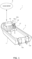
- FIG 1 is a diagram showing a fishing site information providing system 1 according to the preferred embodiment.
- the fishing site information providing system 1 includes a watercraft 2 and a cloud server 3 (exemplary server).
- the watercraft 2 transmits to the cloud server 3 a fishing-related watercraft operating function executed therein and execution formation including a site of execution of the fishing-related watercraft operating function.
- the cloud server 3 estimates a recommended fishing site or sea route based on the fishing-related watercraft operating function and the execution information and then transmits the estimated fishing site or sea route to the watercraft 2.
- the watercraft 2 displays the recommended fishing site or sea route, received thereby from the cloud server 3, on a MFD (Multi-Function Display) 43 (exemplary display device).
- MFD Multi-Function Display
- the watercraft 2 includes a watercraft body 11, a first marine propulsion device 12a, and a second marine propulsion device 12b. It should be noted that the number of marine propulsion devices is not limited to two. The number of the marine propulsion devices may be one. Alternatively, the number of marine propulsion devices may be more than two.
- the first and second marine propulsion devices 12a and 12b are attached to the stem of the watercraft body 11.
- the first and second marine propulsion devices 12a and 12b are outboard motors.
- the first and second marine propulsion devices 12a and 12b are disposed in alignment in the width direction of the watercraft body 11.
- the first marine propulsion device 12a is disposed on the starboard side of the watercraft body 11.
- the second marine propulsion device 12b is disposed on the port side of the watercraft body 11.
- the first and second marine propulsion devices 12a and 12b each generate a thrust for propelling the watercraft body 11.
- the first marine propulsion device 12a includes a first engine 21a, a first drive shaft 22a, a first propeller shaft 23a, and a first shift mechanism 24a.
- the first engine 21a generates the thrust for propelling the watercraft 2.
- the first engine 21a is an internal combustion engine.
- the first engine 21a includes a crankshaft 31a.
- the crankshaft 31a extends in the up-and-down direction of the first marine propulsion device 12a.
- the first drive shaft 22a is connected to the crankshaft 31a.
- the first drive shaft 22a extends in the up-and-down direction of the first marine propulsion device 12a.
- the first propeller shaft 23a extends in the back-and-forth direction of the first marine propulsion device 12a.
- the first propeller shaft 23a is connected to the first drive shaft 22a through the first shift mechanism 24a.
- a propeller 25a is attached to the first propeller shaft 23a.
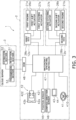
- FIG 3 is a schematic diagram showing a configuration of the fishing site information providing system 1.
- the first marine propulsion device 12a includes a first shift actuator 26a and a first steering actuator 27a.
- the first shift actuator 26a is connected to the dog clutch 34a of the first shift mechanism 24a.
- the first shift actuator 26a actuates the dog clutch 34a to switch gear engagement of each gear 32a, 33a. Movement of the watercraft 2 is thereby switched between forward movement and rearward movement.
- the first shift actuator 26a is, for instance, an electric motor.
- the first shift actuator 26a may be another type of actuator such as an electric cylinder, a hydraulic motor, or a hydraulic cylinder.
- the first steering actuator 27a is provided in the watercraft body 11 and is connected to the first marine propulsion device 12a.
- the first steering actuator 27a rotates the first marine propulsion device 12a about the first steering shaft 14a. Accordingly, the first marine propulsion device 12a is changed in rudder angle.
- the rudder angle refers to the angle of the first propeller shaft 23a with respect to the back-and-forth direction of the first marine propulsion device 12a.
- the first steering actuator 27a is, for instance, an electric motor. However, the first steering actuator 27a may be another type of actuator such as an electric cylinder, a hydraulic motor, or a hydraulic cylinder.
- the second marine propulsion device 12b includes a second engine 21b, a second shift actuator 26b, a second steering actuator 27b, and a second ECU 28b.
- the second marine propulsion device 12b is rotatable about a second steering shaft (configured in similar manner to the first steering shaft 14a shown in FIG 2 , albeit not shown in the drawings).
- the second engine 21b, the second shift actuator 26b, the second steering actuator 27b, and the second ECU 28b in the second marine propulsion device 12b are configured in similar manner to the first engine 21a, the first shift actuator 26a, the first steering actuator 27a, and the first ECU 28a in the first marine propulsion device 12a, respectively.
- the second throttle lever 42b is a device for allowing the operator to regulate the magnitude of the thrust generated by the second marine propulsion device 12b.
- the second throttle lever 42b is also a device for allowing the operator to switch the direction of the thrust generated by the second marine propulsion device 12b between the forward moving direction and the rearward moving direction.
- the second throttle lever 42b is configured in similar manner to the first throttle lever 42a.
- the second throttle lever 42b includes a sensor 422.
- the sensor 422 outputs a second throttle signal indicating the operating direction and the operating amount of the second throttle lever 42b.
- the MFD 43 displays a nautical chart and atmospheric phenomena.
- the atmospheric phenomena include wind direction, wind speed, water temperature, air temperature, precipitation, and so forth.
- the MFD 43 displays fishing-related watercraft operating functions selectable by the operator. Although described below in detail, the fishing-related watercraft operating functions include a position maintaining function, a compass direction maintaining function, a predetermined navigation function, and so forth.
- the MFD 43 displays information regarding a recommended fishing site or sea route received from the cloud server 3.
- the MFD 43 displays the velocity of watercraft and the rotational speed of engine.
- the MFD 43 includes an input device 44 (exemplary selection device).
- the input device 44 can be exemplified as being made in form of a touchscreen but may be made in form of switches, buttons, or so forth.
- the input device 44 is operable by the operator to select one of the fishing-related watercraft operating functions (described below in detail) displayed on the MFD 43.
- the input device 44 outputs a function selecting signal indicating selected one of the fishing-related watercraft operating functions.
- the input device 44 is operable by the operator to select one of sea areas recommended for fishing displayed on the MFD 43.
- the input device 44 outputs a sea area selecting signal indicating selected one of the sea areas.
- the input device 44 may receive fishing result information inputted by the operator as an exemplary fishing result information inputting device.
- the watercraft operating controller 47 outputs a first shift command for the first shift actuator 26a in accordance with the operating direction of the first throttle lever 42a. In response, shifting between a forward moving action and a rearward moving action by the first marine propulsion device 12a is made.
- the watercraft operating controller 47 outputs a first throttle command for the first engine 21a in accordance with the operating amount of the first throttle lever 42a.
- the first ECU 28a controls the thrust of the first marine propulsion device 12a in accordance with the first throttle command.
- the first throttle signal outputted from the sensor 421 may be directly inputted to the first ECU 28a.
- the first ECU 28a may output the first throttle command to the first engine 21a in accordance with the first throttle signal inputted thereto from the sensor 421.
- the watercraft operating controller 47 controls the first and second steering actuators 27a and 27b such that the first and second marine propulsion devices 12a and 12b are rotated leftward.
- the watercraft 2 thereby turns rightward.
- the watercraft operating controller 47 controls the rudder angle of the first marine propulsion device 12a and that of the second marine propulsion device 12b in accordance with the operating amount of the steering wheel 41.
- the position maintaining function (Fish Point function) is provided as one of the fishing-related watercraft operating functions.
- the position maintaining function is used for conducting fishing in a stationary state of watercraft.
- FIG 4A and 4B are diagrams for explaining the position maintaining function.
- the position maintaining function is executed such that the position of the watercraft 2 can be maintained by slightly moving the watercraft 2 back and forth in a condition of wind W blowing from the bow side to the stem side of the watercraft 2.
- the position maintaining function is executed such that the position of the watercraft 2 can be maintained by slightly moving the watercraft 2 back and forth in a condition of wind W blowing from the stem side to the bow side of the watercraft 2.
- the watercraft operating controller 47 controls each marine propulsion device 12a, 12b based on the position signal transmitted thereto from the position sensor 45, for instance, such that the watercraft 2 can be kept located in a predetermined position as much as possible, while being regulated to be moved back and forth at a quite low velocity.
- the predetermined position, in which the watercraft 2 is kept located may be set by selecting a position on the nautical chart displayed on the MFD 43.
- the predetermined position, in which the watercraft 2 is kept located may be set by allowing the operator to select the position maintaining function with the input device 44 when the watercraft 2 reaches a position intended to keep the watercraft 2 located.
- the compass direction maintaining function (Drift Point function) is provided as one of the fishing-related watercraft operating functions.
- the compass direction maintaining function is used for conducting trolling. Under the compass direction maintaining function, the watercraft 2 moves along the wind or tide, while the compass direction thereof is maintained.
- FIG 5 is a diagram for explaining the compass direction maintaining function. In FIG 5 , the compass direction maintaining function is executed such that the orientation of the watercraft 2 is fixed in a condition of wind W blowing from the port bow side to the starboard stem side of the watercraft 2.
- the watercraft operating controller 47 controls each marine propulsion device 12a, 12b such that the watercraft 2 can be kept oriented in a predetermined compass direction based on the compass direction signal transmitted to the watercraft operating controller 47 from the compass direction sensor 46.
- the watercraft 2 moved by the wind W is depicted with dashed two-dotted line.
- the predetermined navigation function (Pattern Steer function) is provided as one of the fishing-related watercraft operating functions. Under the predetermined navigation function, the watercraft 2 is caused to navigate in a sea route pattern preliminarily set. A plurality of sea route patterns can be set under the predetermined navigation function. The operator is allowed to select, with the input device 44, any one of the plural sea route patterns set under the predetermined navigation function. For example, the predetermined navigation function is used for searching a spot good for fishing.
- the plural sea route patterns include a first sea route pattern A1, i.e., a zigzag pattern depicted in FIG 6 .
- the watercraft operating controller 47 controls each marine propulsion device 12a, 12b such that the watercraft 2 moves in the zigzag pattern.
- the first sea route pattern A1 can be set by allowing the operator to input a distance L1 of a straight moving portion of the zigzag pattern and an angle ⁇ between the straight moving portions.
- the watercraft 2 includes a DCM (Data Communication Module) 48 (exemplary communication device).
- the DCM 48 is connected to the watercraft operating controller 47.
- the DCM 48 transmits the following to the cloud server 3: a fishing-related information signal indicating an executed fishing-related watercraft operating function and execution information regarding the executed fishing-related watercraft operating function.
- the executed fishing-related watercraft operating function is the one selected and executed among the functions described above, i.e., the position maintaining function, the compass direction maintaining function, and the predetermined navigation function.
- the execution information includes a site, time, air temperature, water temperature, and weather conditions, all of which are obtained in execution of the fishing-related watercraft operating function.
- FIG 11 is a diagram for explaining estimation of a recommended fishing site.
- a land is denoted by G
- the sea is denoted by S.
- Positions, in which the position maintaining function has been executed, are depicted as points A0.
- Sea routes, in which the compass direction maintaining function has been executed, are depicted as sea route patterns A6.
- the estimation section 52 estimates a sea area, in which the position maintaining function has been executed in a large number of positions, as a recommended sea area R1 recommended for fishing (exemplary recommended fishing site). For example, when the points A0, greater or equal in number to a predetermined value, exist within a range of predetermined distance, the estimation section 52 is enabled to estimate a sea area satisfying the condition as the recommended fishing site.
- the estimation section 52 estimates a sea area, in which the compass direction maintaining function has been executed in a large number of sea routes, as recommended sea areas R2 and R3 recommended for fishing (exemplary recommended fishing site or sea route). For example, when the sea route pattern A6, greater or equal in number to a predetermined value, exist within a range of predetermined distance, the estimation section 52 is enabled to set a sea area satisfying the condition as the recommended fishing site. In FIG 12 , two recommended sea areas R2 and R3 recommended for fishing are depicted.
- the estimation section 52 estimates a sea area, in which the predetermined navigation function has been executed in a large number of sea routes, as recommended sea areas R4 and R5 recommended for fishing (exemplary recommended fishing site or route). For example, when sea route patterns A1 to A5, greater or equal in number to a predetermined value, exist within a range of predetermined distance, the estimation section 52 is enabled to set a sea area satisfying the condition as the recommended fishing site. It should be noted that sea areas, in each of which each type of sea route patterns A1 to A5 exists in large number, may be detected and estimated as the recommended sea areas. It should be noted that the recommended sea area R1, in which the position maintaining function has been executed in a large number of positions, is also depicted in FIG 13 .
- the estimation section 52 may estimate a sea area recommended for fishing based on the fishing result information inputted to the input device 44. For example, among the sea areas R1, R4, and R5, only the one in which the best fishing result has been obtained may be estimated as the recommended sea area.
- the fishing site information signal indicating only the information of the recommended sea area without including the information of the other sea areas, may be transmitted to the DCM 48.
- the fishing site information may be transmitted to the DCM 48, while the sea areas are ranked by recommendation grade such that the recommendation grade becomes higher as the fishing result becomes better.
- the estimation section 52 may estimate a sea area recommended for fishing based on a combination of the plural fishing-related watercraft operating functions and the execution information regarding each fishing-related watercraft operating function. For example, when the position maintaining function has been executed after execution of the predetermined navigation function, it is deducible that, after searching fish, fishing has been conducted at a fishing point found by search; hence, the position may be estimated as the sea area recommended for fishing. For example, as shown in FIG 14 , after execution of the plural first sea route patterns A1 under the predetermined navigation function, the position maintaining function has been executed in the plural points A0; hence, a sea area R4a within the sea area R4 may be estimated as the recommended sea area.
- the estimation section 52 may transmit the fishing site information signal to the DCM 48, while one of the recommended sea areas, estimated based on the combination of the plural fishing-related watercraft operating functions, is set higher in recommendation grade than the others.
- the estimation section 52 may transmit the fishing site information signal to the DCM 48, while one of the recommended sea areas, estimated based on execution of a specific one of the plural fishing-related watercraft operating functions and the execution information regarding the specific fishing-related watercraft operating function, is set higher in recommendation grade than the others.
- the recommended sea area R1 in which the position maintaining function has been executed, is enabled to be set higher in recommendation grade than the other recommended sea areas R4 and R5.
- the estimation section 52 may transmit the fishing site information signal to the DCM 48, while one of the recommended sea areas, in which environmental information (including air temperature, water temperature, and weather conditions) obtained in execution of the fishing-related watercraft operating function is the closest to the present environmental information, is set higher in recommendation grade than the others. For example, when the recommended sea areas R1, R4, and R5 are different in water temperature from each other in FIG 13 and the water temperature in the recommended sea area R4 is the closest to the present water temperature, the fishing site information signal is transmitted to the DCM 48, while the recommended sea area R4 is set higher in recommendation grade than the other recommended sea areas R1 and R5.
- environmental information including air temperature, water temperature, and weather conditions
- the estimation section 52 may set one of the recommended sea areas higher in recommendation grade than the others based on the one executed recently among the fishing-related watercraft operating functions. For example, when a clock time, at which the predetermined navigation function has been executed in the recommended sea area R4, is the closest to the present clock time in FIG 13 , the fishing site information signal is transmitted to the DCM 48, while the recommended sea area R4 is set higher in recommendation grade than the other recommended sea areas R1 and R5.
- FIG 15 is a diagram exemplifying a screen displayed on the MFD 43.
- the recommended sea areas R1 to R5 are displayed on the MFD 43.
- the MFD 43 may display the recommended sea areas R1 to R5 in an arbitrary manner as long as the recommended sea areas R1 to R5 are recognizable by the operator.
- the MFD 43 can display the recommended sea areas R1 to R5 on the nautical chart by, for instance, enclosing the outline of each recommended sea area with line or painting the recommended sea areas in different colors.
- the MFD 43 When receiving the fishing site information through the DCM 48, the MFD 43 displays one of the recommended sea areas, which is higher in recommendation grade than the others, with higher priority than the others.
- the recommended sea area higher in recommendation grade than the others may be displayed with higher priority than the others on the MFD 43 by blinking the line enclosing the recommended sea area higher in recommendation grade than the others or paining the recommended sea area higher in recommendation grade than the others with a different color from the others.
- the lines enclosing the recommended sea areas may be increased in brightness or saturation with recommendation grade.
- only the recommended sea area higher in recommendation grade than the others may be displayed firstly; then, the others may be sequentially displayed by, for instance, tapping the screen.
- the watercraft operating controller 47 controls each marine propulsion device 12a, 12b such that the watercraft 2 automatically moves to a selected fishing site or such that the watercraft 2 automatically moves along a selected sea route. For example, when the recommended sea area R1 is selected, the watercraft operating controller 47 automatically moves the watercraft 2 to the recommended sea area R1 as the selected fishing site. For example, when the recommended sea area R2, R3, R4, or R5 is selected, the watercraft operating controller 47 automatically navigates the watercraft 2 to the recommended sea area R2, R3, R4, or R5 and then automatically moves the watercraft 2 along the recommended sea area R2, R3, R4, or R5 as the selected sea route. It should be noted that in FIG 15 , a plurality of recommended sea areas recommended for fishing are displayed on the MFD 43; alternatively, only one recommended sea area recommended for fishing may be displayed thereon.
- the watercraft operating controller 47 may automatically move the watercraft 2 to the selected recommended sea area, and then, may execute the fishing-related watercraft operating function that has been executed in the selected recommended sea area. For example, when the operator selects the recommended sea area R1, the watercraft operating controller 47 automatically moves the watercraft 2 to the recommended sea area R1, and then, controls each marine propulsion device 12a, 12b to automatically execute the position maintaining function. When the operator selects the recommended sea area R2, the watercraft operating controller 47 automatically moves the watercraft 2 to the recommended sea area R2, and then, controls each marine propulsion device 12a, 12b to automatically execute the compass direction maintaining function.
- the watercraft operating controller 47 automatically moves the watercraft 2 to the recommended area R4, and then, controls each marine propulsion device 12a, 12b to automatically execute the zigzag-shaped sea route pattern A1 under the predetermined navigation function.
- the watercraft 2 may not be automatically moved to the recommended sea area selected by the operator as described above.
- the watercraft operating controller 47 may display a sea route toward the selected sea area on the MFD 43.
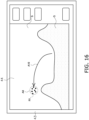
- FIG 16 shows that, when the recommended sea area R1 is selected, a sea route A10 toward the recommended sea area R1 is displayed on the display screen.
- the watercraft 2 can be moved toward the recommended sea area desired by the operator by allowing the operator to operate the watercraft 2 based on the seat route.
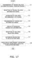
- FIG 17 is a flowchart exemplifying the series of actions performed by the fishing site information providing system.
- step S1 the watercraft 2 transmits a fishing-related information signal, including an executed one of the fishing-related watercraft operating functions and execution information regarding the executed one, from the DCM 48 to the cloud server 3.
- the fishing-related information signal may be transmitted every time the fishing-related watercraft operating function is executed; alternatively, the fishing-related information signals may be collectively transmitted at predetermined intervals of time.
- step S2 the cloud server 3 receives the fishing-related information signal from the watercraft 2. It is preferable for the cloud server 3 to receive the fishing-related information signals from a plurality of watercrafts 2.
- step S3 the estimation section 52 of the cloud server 3 estimates a recommended sea area recommended for fishing based on the executed one of the fishing-related watercraft operating functions and the execution information regarding the executed one, both of which are indicated by the received fishing-related information signal.
- step S4 the transmission section 53 of the cloud server 3 transmits the fishing site information signal, indicating fishing site information of the recommended sea area estimated above, to the watercraft 2.
- the fishing site information signal may be transmitted to only the watercraft 2 requesting the cloud server 3 to provide the fishing site information thereto; alternatively, the fishing site information may be transmitted to all of a single or plurality of watercrafts 2 existing in the recommended sea area relevant to the fishing site information to be provided.
- step S5 the watercraft 2 displays the fishing site information of the recommended sea area on the MFD 43 based on the fishing site information signal received through the DCM 48. For example, as shown in FIG 15 , the recommended sea areas R1 to R5 recommended for fishing are displayed on the MFD 43.
- step S6 when the operator selects any of the recommended sea areas R1 to R5 with the input device 44, the watercraft operating controller 47 receives the sea area selecting signal from the input device 44.
- step S7 the watercraft operating controller 47 controls each marine propulsion device 12a, 12b such that the watercraft 2 automatically moves to the selected one of the recommended sea areas.
- step S7 instead of automatically moving the watercraft 2 to the selected recommended sea area, a sea route toward the selected recommended sea area may be displayed on the MFD 43 as shown in FIG 16 .
- step S8 when the watercraft 2 reaches the selected recommended sea area, the watercraft operating controller 47 executes the fishing-related watercraft operating function that has been executed in the selected recommended sea area.
- the fishing-related watercraft operating function may be automatically executed after the watercraft 2 reaches the recommended sea area; alternatively, the fishing-related watercraft operating function may be executed when the operator selects execution of the fishing-related watercraft operating function.
- the following control may be executed:
- the MFD 43 displays a button for selecting whether or not to execute the fishing-related watercraft operating function that has been executed in the selected recommended sea area; then, when the button is operated by the operator for selecting execution of the fishing-related watercraft operating function, the watercraft operating controller 47 execute the fishing-related watercraft operating function.
- the fishing-related watercraft operating function and the execution information are transmitted from the watercraft 2 to the cloud server 3; hence, manual input work is not required for the operator. In other words, it is possible to accumulate information related to fishing in the cloud server 3 without requiring the operator to perform bothersome work.
- the DCM 48 is installed in the watercraft 2 as an exemplary device for communicating with the cloud server 3; the communication device is not limited to the DCM 48.
- a mobile terminal brought onto the watercraft 2, may be connected with the watercraft operating controller 47 and the cloud server 3.
- the fishing-related information signal is transmitted from the mobile terminal to the cloud server 3.
- the fishing site information signal transmitted from the cloud server 3, is received by the watercraft operating controller 47 through the mobile terminal.
- the operator may input the fishing result information not to the MFD 43 but instead to the mobile terminal.
- each marine propulsion device 12a, 12b is described as the outboard motor; however, each marine propulsion device 12a, 12b may be another type of device without being limited to the outboard motor.
- each marine propulsion device 12a, 12b may be an inboard engine outboard drive or a jet propulsion device.
- a fishing site information providing system a fishing site information providing method, and a server, whereby it is enabled to determine accurately, without requiring an operator to perform bothersome work, that fishing has been conducted and to suggest the operator a recommended fishing site.
Landscapes
- Engineering & Computer Science (AREA)
- Radar, Positioning & Navigation (AREA)
- Remote Sensing (AREA)
- Ocean & Marine Engineering (AREA)
- Physics & Mathematics (AREA)
- General Physics & Mathematics (AREA)
- Combustion & Propulsion (AREA)
- Mechanical Engineering (AREA)
- Chemical & Material Sciences (AREA)
- Business, Economics & Management (AREA)
- Life Sciences & Earth Sciences (AREA)
- Automation & Control Theory (AREA)
- Economics (AREA)
- Strategic Management (AREA)
- Human Resources & Organizations (AREA)
- Environmental Sciences (AREA)
- Marine Sciences & Fisheries (AREA)
- Animal Husbandry (AREA)
- Theoretical Computer Science (AREA)
- General Business, Economics & Management (AREA)
- Aviation & Aerospace Engineering (AREA)
- Tourism & Hospitality (AREA)
- Marketing (AREA)
- Biodiversity & Conservation Biology (AREA)
- Development Economics (AREA)
- Agronomy & Crop Science (AREA)
- General Health & Medical Sciences (AREA)
- Health & Medical Sciences (AREA)
- Primary Health Care (AREA)
- Mining & Mineral Resources (AREA)
- Game Theory and Decision Science (AREA)
- Entrepreneurship & Innovation (AREA)
- Operations Research (AREA)
- Quality & Reliability (AREA)
- Navigation (AREA)
- Management, Administration, Business Operations System, And Electronic Commerce (AREA)
Abstract
Description
- The present invention relates to a fishing site information providing system, a fishing site information providing method, and a server.
- There has been disclosed a device that uploads information of fish catches, hydrographic conditions, and so forth to a cloud, conducts an AI (Artificial Intelligence) based analysis for the uploaded information, and suggests a recommended fishing ground (e.g.,
Patent Literatures 1 and 2:JP 2020-160749 A JP 2006-158239 A - By contrast, there has been also disclosed a technology for automatically determining whether or not a watercraft is in an operating state (i.e., the watercraft is operated to search catch targets) without informational input by a user (e.g., see Patent Literature 3:
JP 2020-13339 A Patent Literature 3, it is determined whether or not the watercraft is in the operating state based on speed information obtained from positional information and status-identifiable information of the watercraft. - However, the user is required to perform bothersome work in use of such functions as described in
Patent Literatures Literature 1; the user is firstly required to continue inputting information of fish catch for oneself. If the user forget inputting the information, the information is not reflected on a database; the user cannot fully utilize the functions. - In the technology described in
Patent Literature 3, it is automatically determined whether or not the watercraft is in the operating state without informational input by the user; however, it is determined whether or not the watercraft is in a state of commercial or recreational fishing based on the positional information and movement of the watercraft, whereby it is made difficult to enhance accuracy of the determination. For example, even when the watercraft stays in approximately the same position, it is difficult to distinguish between whether the watercraft does so for conducting fishing in a fixed spot and whether the watercraft simply stops in a no wind-wave condition. On the other hand, when the watercraft is moving slowly, it is difficult to distinguish between whether the watercraft is simply drifting with tide and whether the watercraft is moving slowly for conducting trolling. - It is an object of the present invention to provide a fishing site information providing system, a fishing site information providing method, and a server, whereby it is made possible to accurately determine that fishing has been conducted without requiring an operator to perform bothersome work and to suggest the operator a recommended fishing site.
- A fishing site information providing system according to a first aspect of the present disclosure is the one including a server and a watercraft. The watercraft includes a position detecting section, a marine propulsion device, an input device, and a controller. The position detecting section detects a position of the watercraft. The input device is operable by an operator to select a fishing-related watercraft operating function of the marine propulsion device. The controller is connected to the input device and controls the marine propulsion device to execute the fishing-related watercraft operating function selected by the operator. The controller is connectable to a communication device and a display device. The communication device transmits to the server the fishing-related watercraft operating function executed by the marine propulsion device and execution information including a site of execution of the fishing-related watercraft operating function. The server estimates a recommended fishing site or sea route based on the fishing-related watercraft operating function and the execution information and transmits the recommended fishing site or sea route estimated thereby to the communication device. The controller controls the display device to display the recommended fishing site or sea route estimated by the server.
- A fishing site information providing method according to a second aspect of the present disclosure includes the following processes. The first process relates to causing a transmission device to transmit to a server a fishing-related watercraft operating function executed in a watercraft and execution information including a site of execution of the fishing-related watercraft operating function. The second process relates to causing the server to estimate a recommended fishing site or sea route based on the fishing-related watercraft operating function and the execution information. The third process relates to causing the server to transmit to the communication device the recommended fishing site or sea route estimated by the server. The fourth process relates to causing a display device to display the recommended fishing site or sea route estimated by the server.
- A server according to a third aspect of the present disclosure includes a reception section, an estimation section, and a transmission section. The reception section receives a fishing-related watercraft operating function executed in a watercraft and execution information including a site of execution of the fishing-related watercraft operating function. The estimation section estimates a recommended fishing site or sea route based on the fishing-related watercraft operating function and the execution information. The transmission section transmits the recommended fishing site or sea route estimated by the estimation section to a communication device of the watercraft.
- Overall, when the fishing-related watercraft operating function has been executed, it is thereby deductible that fishing has been conducted in the site of execution of the fishing-related watercraft operation function; hence, it is possible to accurately determine whether or not fishing has been conducted. Besides, the fishing-related watercraft operating function and the execution information are transmitted from the watercraft to the server; hence, manual input work is not required for the operator. In other words, it is possible to accumulate information related to fishing in the server without requiring the operator to perform bothersome work. This makes it possible for the server to estimate a recommended fishing site and to suggest the operator the recommended fishing site without requiring the operator to perform bothersome work.
-
-
FIG 1 is a diagram showing a configuration of a fishing site information providing system according to a preferred embodiment. -
FIG 2 is a side view of a marine propulsion device. -
FIG 3 is a block diagram showing the configuration of the fishing site information providing system. -
FIG 4A is a diagram for explaining a position maintaining function. - FIG B is a diagram for explaining a position maintaining function.
-
FIG 5 is a diagram for explaining a compass direction maintaining function. -
FIG 6 is a diagram for exemplifying a sea route pattern in a predetermined navigation function. -
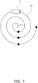
FIG 7 is a diagram for exemplifying another sea route pattern in the predetermined navigation function. -
FIG 8 is a diagram for exemplifying yet another sea route pattern in the predetermined navigation function. -
FIG 9 is a diagram for exemplifying still another sea route pattern in the predetermined navigation function. -
FIG 10 is a diagram for exemplifying still yet another sea route pattern in the predetermined navigation function. -
FIG 11 a diagram for explaining estimation of a recommended fishing site. -
FIG 12 is a diagram for explaining estimation of recommended fishing sites. -
FIG 13 is a diagram for explaining estimation of recommended fishing sites. -
FIG 14 is a diagram for explaining estimation of recommended fishing sites. -
FIG 15 is a diagram exemplifying a screen displayed on an MFD. -
FIG 16 is a diagram exemplifying another screen displayed on the MFD. -
FIG 17 is a flowchart showing a series of actions performed by the fishing site information providing system. - A fishing site information providing system, a server, and a fishing site information providing method according to a preferred embodiment will be hereinafter explained with reference to drawings.
-
FIG 1 is a diagram showing a fishing siteinformation providing system 1 according to the preferred embodiment. The fishing siteinformation providing system 1 includes awatercraft 2 and a cloud server 3 (exemplary server). The watercraft 2 transmits to the cloud server 3 a fishing-related watercraft operating function executed therein and execution formation including a site of execution of the fishing-related watercraft operating function. Thecloud server 3 estimates a recommended fishing site or sea route based on the fishing-related watercraft operating function and the execution information and then transmits the estimated fishing site or sea route to thewatercraft 2. Thewatercraft 2 displays the recommended fishing site or sea route, received thereby from thecloud server 3, on a MFD (Multi-Function Display) 43 (exemplary display device). - The
watercraft 2 includes awatercraft body 11, a firstmarine propulsion device 12a, and a secondmarine propulsion device 12b. It should be noted that the number of marine propulsion devices is not limited to two. The number of the marine propulsion devices may be one. Alternatively, the number of marine propulsion devices may be more than two. - The first and second
marine propulsion devices watercraft body 11. The first and secondmarine propulsion devices marine propulsion devices watercraft body 11. Specifically, the firstmarine propulsion device 12a is disposed on the starboard side of thewatercraft body 11. The secondmarine propulsion device 12b is disposed on the port side of thewatercraft body 11. The first and secondmarine propulsion devices watercraft body 11. -
FIG 2 is a side view of the firstmarine propulsion device 12a. The structure of the firstmarine propulsion device 12a will be hereinafter explained; however, the structure of the secondmarine propulsion device 12b also has a same structure as the firstmarine propulsion device 12a. The firstmarine propulsion device 12a is attached to thewatercraft body 11 through abracket 13a. Thebracket 13a supports the firstmarine propulsion device 12a such that the firstmarine propulsion device 12a is rotatable about afirst steering shaft 14a. Thefirst steering shaft 14a extends in the up-and-down direction of the firstmarine propulsion device 12a. - The first
marine propulsion device 12a includes afirst engine 21a, afirst drive shaft 22a, afirst propeller shaft 23a, and afirst shift mechanism 24a. Thefirst engine 21a generates the thrust for propelling thewatercraft 2. Thefirst engine 21a is an internal combustion engine. Thefirst engine 21a includes acrankshaft 31a. Thecrankshaft 31a extends in the up-and-down direction of the firstmarine propulsion device 12a. Thefirst drive shaft 22a is connected to thecrankshaft 31a. Thefirst drive shaft 22a extends in the up-and-down direction of the firstmarine propulsion device 12a. Thefirst propeller shaft 23a extends in the back-and-forth direction of the firstmarine propulsion device 12a. Thefirst propeller shaft 23a is connected to thefirst drive shaft 22a through thefirst shift mechanism 24a. Apropeller 25a is attached to thefirst propeller shaft 23a. - The
first shift mechanism 24a includes a forward movinggear 32a, a rearward movinggear 33a, and a dog clutch 34a. When gear engagement of eachgear dog clutch 34a, the direction of rotation transmitted from thefirst drive shaft 22a to thefirst propeller shaft 23a is switched. Movement of thewatercraft 2 is thereby switched between forward movement and rearward movement. - When described in detail, the
first shift mechanism 24a is switchable among a forward moving state, a rearward moving state, and a neutral state. When thefirst shift mechanism 24a is set in the forward moving state, thedog clutch 34a is connected to the forward movinggear 32a. Accordingly, the rotation of thefirst drive shaft 22a is transmitted to thefirst propeller shaft 23a so as to rotate thefirst propeller shaft 23a in a corresponding direction to forward movement. When thefirst shift mechanism 24a is set in the rearward moving state, thedog clutch 34a is connected to the rearward movinggear 33a. Accordingly, the rotation of thefirst drive shaft 22a is transmitted to thefirst propeller shaft 23a so as to rotate thefirst propeller shaft 23a in a corresponding direction to rearward movement. When thefirst shift mechanism 24a is set in the neutral state, thedog clutch 34a is released from being connected to each of the forward movinggear 32a and the rearward movinggear 33a. Accordingly, the rotation of thefirst drive shaft 22a is not transmitted to thefirst propeller shaft 23a. -
FIG 3 is a schematic diagram showing a configuration of the fishing siteinformation providing system 1. As shown inFIG 3 , the firstmarine propulsion device 12a includes afirst shift actuator 26a and afirst steering actuator 27a. Thefirst shift actuator 26a is connected to the dog clutch 34a of thefirst shift mechanism 24a. Thefirst shift actuator 26a actuates the dog clutch 34a to switch gear engagement of eachgear watercraft 2 is thereby switched between forward movement and rearward movement. Thefirst shift actuator 26a is, for instance, an electric motor. However, thefirst shift actuator 26a may be another type of actuator such as an electric cylinder, a hydraulic motor, or a hydraulic cylinder. Thefirst steering actuator 27a is provided in thewatercraft body 11 and is connected to the firstmarine propulsion device 12a. Thefirst steering actuator 27a rotates the firstmarine propulsion device 12a about thefirst steering shaft 14a. Accordingly, the firstmarine propulsion device 12a is changed in rudder angle. The rudder angle refers to the angle of thefirst propeller shaft 23a with respect to the back-and-forth direction of the firstmarine propulsion device 12a. Thefirst steering actuator 27a is, for instance, an electric motor. However, thefirst steering actuator 27a may be another type of actuator such as an electric cylinder, a hydraulic motor, or a hydraulic cylinder. - The first
marine propulsion device 12a includes a first ECU (Electric Control Unit) 28a. Thefirst ECU 28a includes a processor such as a CPU (Central Processing Unit) and memories such as a RAM (Random Access Memory) and a ROM (Read Only Memory). Thefirst ECU 28a stores programs and data for controlling the firstmarine propulsion device 12a. Thefirst ECU 28a controls thefirst engine 21a. - The second
marine propulsion device 12b includes asecond engine 21b, a second shift actuator 26b, asecond steering actuator 27b, and asecond ECU 28b. The secondmarine propulsion device 12b is rotatable about a second steering shaft (configured in similar manner to thefirst steering shaft 14a shown inFIG 2 , albeit not shown in the drawings). Thesecond engine 21b, the second shift actuator 26b, thesecond steering actuator 27b, and thesecond ECU 28b in the secondmarine propulsion device 12b are configured in similar manner to thefirst engine 21a, thefirst shift actuator 26a, thefirst steering actuator 27a, and thefirst ECU 28a in the firstmarine propulsion device 12a, respectively. - The
watercraft 2 includes asteering wheel 41, aremote controller 42, and the MFD (Multi-Function Display) 43. As shown inFIG 1 , thesteering wheel 41, theremote controller 42, and theMFD 43 are disposed in a cockpit of thewatercraft 2. - The
steering wheel 41 is a device for allowing an operator to manipulate the turning direction of thewatercraft 2. Thesteering wheel 41 includes asensor 410. Thesensor 410 outputs a steering signal indicating the operating direction and the operating amount of thesteering wheel 41. - The
remote controller 42 includes afirst throttle lever 42a and asecond throttle lever 42b. Thefirst throttle lever 42a is a device for allowing the operator to regulate the magnitude of the thrust generated by the firstmarine propulsion device 12a. Thefirst throttle lever 42a is also a device for allowing the operator to switch the direction of the thrust generated by the firstmarine propulsion device 12a between a forward moving direction and a rearward moving direction. Thefirst throttle lever 42a is operable from a neutral position to a forward moving directional side and a rearward moving directional side. The neutral position is a position located between the forward moving directional side and the rearward moving directional side. Thefirst throttle lever 42a includes asensor 421. Thesensor 421 outputs a first throttle signal indicating the operating direction and the operating amount of thefirst throttle lever 42a. - The
second throttle lever 42b is a device for allowing the operator to regulate the magnitude of the thrust generated by the secondmarine propulsion device 12b. Thesecond throttle lever 42b is also a device for allowing the operator to switch the direction of the thrust generated by the secondmarine propulsion device 12b between the forward moving direction and the rearward moving direction. Thesecond throttle lever 42b is configured in similar manner to thefirst throttle lever 42a. Thesecond throttle lever 42b includes asensor 422. Thesensor 422 outputs a second throttle signal indicating the operating direction and the operating amount of thesecond throttle lever 42b. - The
MFD 43 displays a nautical chart and atmospheric phenomena. The atmospheric phenomena include wind direction, wind speed, water temperature, air temperature, precipitation, and so forth. TheMFD 43 displays fishing-related watercraft operating functions selectable by the operator. Although described below in detail, the fishing-related watercraft operating functions include a position maintaining function, a compass direction maintaining function, a predetermined navigation function, and so forth. TheMFD 43 displays information regarding a recommended fishing site or sea route received from thecloud server 3. TheMFD 43 displays the velocity of watercraft and the rotational speed of engine. - The
MFD 43 includes an input device 44 (exemplary selection device). Theinput device 44 can be exemplified as being made in form of a touchscreen but may be made in form of switches, buttons, or so forth. Theinput device 44 is operable by the operator to select one of the fishing-related watercraft operating functions (described below in detail) displayed on theMFD 43. Theinput device 44 outputs a function selecting signal indicating selected one of the fishing-related watercraft operating functions. Theinput device 44 is operable by the operator to select one of sea areas recommended for fishing displayed on theMFD 43. Theinput device 44 outputs a sea area selecting signal indicating selected one of the sea areas. Theinput device 44 may receive fishing result information inputted by the operator as an exemplary fishing result information inputting device. - The
watercraft 2 includes a position sensor 45 (exemplary position detecting section) and acompass direction sensor 46. Theposition sensor 45 detects the present position of thewatercraft 2. Theposition sensor 45 is a GNSS (Global Navigation Satellite System) receiver such as a GPS (Global Positioning System) receiver. However, theposition sensor 45 may be a type of sensor other than the GNSS receiver. Theposition sensor 45 outputs a position signal indicating the present position of thewatercraft 2. - The
watercraft 2 includes thecompass direction sensor 46. Thecompass direction sensor 46 detects the present compass direction of thewatercraft 2. Thecompass direction sensor 46 is, for instance, an electronic compass. However, thecompass direction sensor 46 may be a type of sensor other than the electronic compass. Thecompass direction sensor 46 outputs a compass direction signal indicating the present compass direction of thewatercraft 2. - The
watercraft 2 includes awatercraft operating controller 47. Thewatercraft operating controller 47 includes a processor such as a CPU and memories such as a RAM and a ROM. Thewatercraft operating controller 47 stores programs and data for controlling the first and secondmarine propulsion devices - The
watercraft operating controller 47 is connected to the first andsecond ECUs watercraft operating controller 47 is connected to thesteering wheel 41, theremote controller 42, and theMFD 43. - The
watercraft operating controller 47 receives the steering signal from thesensor 410. Thewatercraft operating controller 47 receives the throttle signal from thesensor watercraft operating controller 47 receives the setting signals from theinput device 44. Thewatercraft operating controller 47 outputs command signals to the first andsecond ECUs sensors input device 44. - The command signals are transmitted to the
first engine 21a, thefirst shift actuator 26a, and thefirst steering actuator 27a through thefirst ECU 28a. The command signals are transmitted to thesecond engine 21b, the second shift actuator 26b, and thesecond steering actuator 27b through thesecond ECU 28b. - The
watercraft operating controller 47 outputs a first shift command for thefirst shift actuator 26a in accordance with the operating direction of thefirst throttle lever 42a. In response, shifting between a forward moving action and a rearward moving action by the firstmarine propulsion device 12a is made. Thewatercraft operating controller 47 outputs a first throttle command for thefirst engine 21a in accordance with the operating amount of thefirst throttle lever 42a. Thefirst ECU 28a controls the thrust of the firstmarine propulsion device 12a in accordance with the first throttle command. It should be noted that the first throttle signal outputted from thesensor 421 may be directly inputted to thefirst ECU 28a. Thefirst ECU 28a may output the first throttle command to thefirst engine 21a in accordance with the first throttle signal inputted thereto from thesensor 421. - The
watercraft operating controller 47 outputs a second shift command for the second shift actuator 26b in accordance with the operating direction of thesecond throttle lever 42b. In response, switching between a forward moving action and a rearward moving action by the secondmarine propulsion device 12b is made. Thewatercraft operating controller 47 outputs a second throttle command for thesecond engine 21b in accordance with the operating amount of thesecond throttle lever 42b. Thesecond ECU 28b controls the thrust of the secondmarine propulsion device 12b in accordance with the second throttle command. It should be noted that the second throttle signal outputted from thesensor 422 may be directly inputted to thesecond ECU 28b. Thesecond ECU 28b may output the second throttle command to thesecond engine 21b in accordance with the second throttle signal inputted thereto from thesensor 422. - The
watercraft operating controller 47 outputs command signals for the first andsecond steering actuators steering wheel 41. When thesteering wheel 41 is operated leftward from the neutral position, thewatercraft operating controller 47 controls the first andsecond steering actuators marine propulsion devices watercraft 2 thereby turns leftward. - When the
steering wheel 41 is operated rightward from the neutral position, thewatercraft operating controller 47 controls the first andsecond steering actuators marine propulsion devices watercraft 2 thereby turns rightward. Besides, thewatercraft operating controller 47 controls the rudder angle of the firstmarine propulsion device 12a and that of the secondmarine propulsion device 12b in accordance with the operating amount of thesteering wheel 41. - The
watercraft operating controller 47 is connected to theposition sensor 45 in communicable manner. Thewatercraft operating controller 47 obtains the position of thewatercraft 2 based on the position signal transmitted thereto from theposition sensor 45. Besides, thewatercraft operating controller 47 obtains the velocity of thewatercraft 2 based on the position signal transmitted thereto from theposition sensor 45. Thewatercraft 2 may include an additional sensor for detecting the velocity of watercraft. Thewatercraft operating controller 47 is connected to thecompass direction sensor 46 in communicable manner. Thewatercraft operating controller 47 obtains the present compass direction of thewatercraft 2 based on the compass direction signal transmitted thereto from thecompass direction sensor 46. - The
watercraft operating controller 47 automatically controls thewatercraft 2 under a predetermined one of the fishing-related watercraft operating functions based on the setting signal transmitted thereto from theinput device 44. Under the predetermined fishing-related watercraft operating function, thewatercraft operating controller 47 controls eachmarine propulsion device steering actuator watercraft 2 moves along a predetermined sea route. - The position maintaining function (Fish Point function) is provided as one of the fishing-related watercraft operating functions. For example, the position maintaining function is used for conducting fishing in a stationary state of watercraft.
FIG 4A and 4B are diagrams for explaining the position maintaining function. InFIG 4A , the position maintaining function is executed such that the position of thewatercraft 2 can be maintained by slightly moving thewatercraft 2 back and forth in a condition of wind W blowing from the bow side to the stem side of thewatercraft 2. InFIG 4B , the position maintaining function is executed such that the position of thewatercraft 2 can be maintained by slightly moving thewatercraft 2 back and forth in a condition of wind W blowing from the stem side to the bow side of thewatercraft 2. When the position maintaining function is selected with theinput device 44, thewatercraft operating controller 47 controls eachmarine propulsion device position sensor 45, for instance, such that thewatercraft 2 can be kept located in a predetermined position as much as possible, while being regulated to be moved back and forth at a quite low velocity. The predetermined position, in which thewatercraft 2 is kept located, may be set by selecting a position on the nautical chart displayed on theMFD 43. The predetermined position, in which thewatercraft 2 is kept located, may be set by allowing the operator to select the position maintaining function with theinput device 44 when thewatercraft 2 reaches a position intended to keep thewatercraft 2 located. - The compass direction maintaining function (Drift Point function) is provided as one of the fishing-related watercraft operating functions. For example, the compass direction maintaining function is used for conducting trolling. Under the compass direction maintaining function, the
watercraft 2 moves along the wind or tide, while the compass direction thereof is maintained.FIG 5 is a diagram for explaining the compass direction maintaining function. InFIG 5 , the compass direction maintaining function is executed such that the orientation of thewatercraft 2 is fixed in a condition of wind W blowing from the port bow side to the starboard stem side of thewatercraft 2. When the compass direction maintaining function is selected with theinput device 44, as shown inFIG 5 , thewatercraft operating controller 47 controls eachmarine propulsion device watercraft 2 can be kept oriented in a predetermined compass direction based on the compass direction signal transmitted to thewatercraft operating controller 47 from thecompass direction sensor 46. InFIG 5 , thewatercraft 2 moved by the wind W is depicted with dashed two-dotted line. - The predetermined navigation function (Pattern Steer function) is provided as one of the fishing-related watercraft operating functions. Under the predetermined navigation function, the
watercraft 2 is caused to navigate in a sea route pattern preliminarily set. A plurality of sea route patterns can be set under the predetermined navigation function. The operator is allowed to select, with theinput device 44, any one of the plural sea route patterns set under the predetermined navigation function. For example, the predetermined navigation function is used for searching a spot good for fishing. - The plural sea route patterns include a first sea route pattern A1, i.e., a zigzag pattern depicted in
FIG 6 . When the first sea route pattern A1 is selected under the predetermined navigation function, thewatercraft operating controller 47 controls eachmarine propulsion device watercraft 2 moves in the zigzag pattern. For example, the first sea route pattern A1 can be set by allowing the operator to input a distance L1 of a straight moving portion of the zigzag pattern and an angle α between the straight moving portions. - The plural sea route patterns include a second sea route pattern A2, i.e., a spiral pattern depicted in
FIG 7 . When the second sea route pattern A2 is selected under the predetermined navigation function, thewatercraft operating controller 47 controls eachmarine propulsion device watercraft 2 moves in the spiral pattern. For example, the second sea route pattern A2 can be set by allowing the operator to input an initial radius r1 and an increase-in-radius Δr in the spiral pattern with theinput device 44. - The plural sea route patterns include a third sea route pattern A3 depicted in
FIG 8 . In the third sea route pattern A3, thewatercraft 2 passes through a target position and then navigates about the target position. When the third sea route pattern A3 is selected under the predetermined navigation function, thewatercraft operating controller 47 controls eachmarine propulsion device watercraft 2 passes through a predetermined position P1 and then moves along a circle with a radius r2 about the predetermined position P1. For example, the third sea route pattern A3 can be set by allowing the operator to input the predetermined position P1 and the radius r2 with theinput device 44. - The plural sea route patterns include a fourth sea route pattern A4 depicted in
FIG 9 such that thewatercraft 2 navigates along an 8-shaped route, in the center of which a target position is located. When the fourth sea route pattern A4 is selected under the predetermined navigation function, thewatercraft operating controller 47 controls eachmarine propulsion device watercraft 2 moves along the 8-shaped route, in the center of which a predetermined position P2 is located. For example, the fourth sea route pattern A4 can be set by allowing the operator to input the predetermined position P2, a moving distance L1, by which thewatercraft 2 moves from the predetermined position P2 along anapproach direction D 1, and a rotation radius r3. - The plural sea route patterns include a fifth sea route pattern A5 depicted in
FIG 10 such that thewatercraft 2 moves in a predetermined direction, while forming circles. When the fifth sea route pattern A5 is selected under the predetermined navigation function, thewatercraft operating controller 47 controls eachmarine propulsion device watercraft 2 moves from a start position P3 in a circular shape and then moves by a distance L2 from a position oriented in the same direction as an approach direction D2. For example, the fifth sea route pattern A5 can be set by allowing the operator to input the start position P3, a rotation radius r4, the distance L2, and an end position P4 with theinput device 44. - As shown in
FIG 3 , thewatercraft 2 includes a DCM (Data Communication Module) 48 (exemplary communication device). TheDCM 48 is connected to thewatercraft operating controller 47. TheDCM 48 transmits the following to the cloud server 3: a fishing-related information signal indicating an executed fishing-related watercraft operating function and execution information regarding the executed fishing-related watercraft operating function. The executed fishing-related watercraft operating function is the one selected and executed among the functions described above, i.e., the position maintaining function, the compass direction maintaining function, and the predetermined navigation function. The execution information includes a site, time, air temperature, water temperature, and weather conditions, all of which are obtained in execution of the fishing-related watercraft operating function. The site is outputted, as the position signal, to thewatercraft operating controller 47 by theposition sensor 45. The time, air temperature, water temperature, and weather conditions are transmitted, as weather signals, to thewatercraft operating controller 47 by theMFD 43. Thewatercraft operating controller 47 outputs the fishing-related information signal to theDCM 48, while the execution information regarding execution of the fishing-related watercraft operating function is associated with the executed fishing-related watercraft operating function. Thewatercraft operating controller 47 may causes theDCM 48 to transmit the fishing-related information signal to thecloud server 3, while the fishing result information, inputted to theinput device 44, is added to the executed fishing-related watercraft operating function and the execution information as the fishing-related information signal. It should be noted that the fishing-related information signal may not be necessarily transmitted to thecloud server 3 from thesingle watercraft 2; alternatively, the fishing-related information signals may be transmitted to thecloud server 3 from a plurality ofwatercrafts 2. TheDCM 48 receives a fishing site information signal (to be described) transmitted from thecloud server 3. - As shown in
FIG 3 , thecloud server 3 includes areception section 51, anestimation section 52, and atransmission section 53. Thereception section 51 receives the fishing-related information signal from each of the single or plurality ofwatercrafts 2. Theestimation section 52 estimates a recommended fishing site or sea route based on the fishing-related information signal received by thereception section 51. For example, theestimation section 52 sets a sea area, in which a predetermined one of the fishing-related watercraft operating functions has been executed in a large number of positions, as the recommended fishing site or sea route. Thetransmission section 53 transmits the fishing site information signal, indicating the recommended fishing site or sea route estimated by theestimation section 52, to theDCM 48. The fishing site information, transmitted from thecloud server 3, is displayed on theMFD 43. - Next, estimation of a recommended fishing site by the
estimation section 52 will be explained.FIG 11 is a diagram for explaining estimation of a recommended fishing site. InFIG 11 , a land is denoted by G, while the sea is denoted by S. Positions, in which the position maintaining function has been executed, are depicted as points A0. Sea routes, in which the compass direction maintaining function has been executed, are depicted as sea route patterns A6. - As shown in
FIG 11 , theestimation section 52 estimates a sea area, in which the position maintaining function has been executed in a large number of positions, as a recommended sea area R1 recommended for fishing (exemplary recommended fishing site). For example, when the points A0, greater or equal in number to a predetermined value, exist within a range of predetermined distance, theestimation section 52 is enabled to estimate a sea area satisfying the condition as the recommended fishing site. - As shown in
FIG 12 , theestimation section 52 estimates a sea area, in which the compass direction maintaining function has been executed in a large number of sea routes, as recommended sea areas R2 and R3 recommended for fishing (exemplary recommended fishing site or sea route). For example, when the sea route pattern A6, greater or equal in number to a predetermined value, exist within a range of predetermined distance, theestimation section 52 is enabled to set a sea area satisfying the condition as the recommended fishing site. InFIG 12 , two recommended sea areas R2 and R3 recommended for fishing are depicted. - As shown in
FIG 13 , theestimation section 52 estimates a sea area, in which the predetermined navigation function has been executed in a large number of sea routes, as recommended sea areas R4 and R5 recommended for fishing (exemplary recommended fishing site or route). For example, when sea route patterns A1 to A5, greater or equal in number to a predetermined value, exist within a range of predetermined distance, theestimation section 52 is enabled to set a sea area satisfying the condition as the recommended fishing site. It should be noted that sea areas, in each of which each type of sea route patterns A1 to A5 exists in large number, may be detected and estimated as the recommended sea areas. It should be noted that the recommended sea area R1, in which the position maintaining function has been executed in a large number of positions, is also depicted inFIG 13 . - The
estimation section 52 may estimate a sea area recommended for fishing based on the fishing result information inputted to theinput device 44. For example, among the sea areas R1, R4, and R5, only the one in which the best fishing result has been obtained may be estimated as the recommended sea area. In this case, the fishing site information signal, indicating only the information of the recommended sea area without including the information of the other sea areas, may be transmitted to theDCM 48. Besides, the fishing site information may be transmitted to theDCM 48, while the sea areas are ranked by recommendation grade such that the recommendation grade becomes higher as the fishing result becomes better. - When the plural fishing-related watercraft operating functions are executed, the
estimation section 52 may estimate a sea area recommended for fishing based on a combination of the plural fishing-related watercraft operating functions and the execution information regarding each fishing-related watercraft operating function. For example, when the position maintaining function has been executed after execution of the predetermined navigation function, it is deducible that, after searching fish, fishing has been conducted at a fishing point found by search; hence, the position may be estimated as the sea area recommended for fishing. For example, as shown inFIG 14 , after execution of the plural first sea route patterns A1 under the predetermined navigation function, the position maintaining function has been executed in the plural points A0; hence, a sea area R4a within the sea area R4 may be estimated as the recommended sea area. - The
estimation section 52 may transmit the fishing site information signal to theDCM 48, while one of the recommended sea areas, estimated based on the combination of the plural fishing-related watercraft operating functions, is set higher in recommendation grade than the others. - The
estimation section 52 may transmit the fishing site information signal to theDCM 48, while one of the recommended sea areas, estimated based on execution of a specific one of the plural fishing-related watercraft operating functions and the execution information regarding the specific fishing-related watercraft operating function, is set higher in recommendation grade than the others. For example, inFIG 13 , when the position maintaining function is set as the specific fishing-related watercraft operating function, the recommended sea area R1, in which the position maintaining function has been executed, is enabled to be set higher in recommendation grade than the other recommended sea areas R4 and R5. - The
estimation section 52 may transmit the fishing site information signal to theDCM 48, while one of the recommended sea areas, in which environmental information (including air temperature, water temperature, and weather conditions) obtained in execution of the fishing-related watercraft operating function is the closest to the present environmental information, is set higher in recommendation grade than the others. For example, when the recommended sea areas R1, R4, and R5 are different in water temperature from each other inFIG 13 and the water temperature in the recommended sea area R4 is the closest to the present water temperature, the fishing site information signal is transmitted to theDCM 48, while the recommended sea area R4 is set higher in recommendation grade than the other recommended sea areas R1 and R5. - The
estimation section 52 may set one of the recommended sea areas higher in recommendation grade than the others based on the one executed recently among the fishing-related watercraft operating functions. For example, when a clock time, at which the predetermined navigation function has been executed in the recommended sea area R4, is the closest to the present clock time inFIG 13 , the fishing site information signal is transmitted to theDCM 48, while the recommended sea area R4 is set higher in recommendation grade than the other recommended sea areas R1 and R5. - The fishing site information, transmitted to the
DCM 48, is displayed on theMFD 43.FIG 15 is a diagram exemplifying a screen displayed on theMFD 43. As shown inFIG 15 , the recommended sea areas R1 to R5 are displayed on theMFD 43. TheMFD 43 may display the recommended sea areas R1 to R5 in an arbitrary manner as long as the recommended sea areas R1 to R5 are recognizable by the operator. TheMFD 43 can display the recommended sea areas R1 to R5 on the nautical chart by, for instance, enclosing the outline of each recommended sea area with line or painting the recommended sea areas in different colors. - When receiving the fishing site information through the
DCM 48, theMFD 43 displays one of the recommended sea areas, which is higher in recommendation grade than the others, with higher priority than the others. For example, the recommended sea area higher in recommendation grade than the others may be displayed with higher priority than the others on theMFD 43 by blinking the line enclosing the recommended sea area higher in recommendation grade than the others or paining the recommended sea area higher in recommendation grade than the others with a different color from the others. The lines enclosing the recommended sea areas may be increased in brightness or saturation with recommendation grade. Alternatively, only the recommended sea area higher in recommendation grade than the others may be displayed firstly; then, the others may be sequentially displayed by, for instance, tapping the screen. - When the operator selects any one from the recommended sea areas R1 to R5 recommended for fishing that are displayed on the
MFD 43, thewatercraft operating controller 47 controls eachmarine propulsion device watercraft 2 automatically moves to a selected fishing site or such that thewatercraft 2 automatically moves along a selected sea route. For example, when the recommended sea area R1 is selected, thewatercraft operating controller 47 automatically moves thewatercraft 2 to the recommended sea area R1 as the selected fishing site. For example, when the recommended sea area R2, R3, R4, or R5 is selected, thewatercraft operating controller 47 automatically navigates thewatercraft 2 to the recommended sea area R2, R3, R4, or R5 and then automatically moves thewatercraft 2 along the recommended sea area R2, R3, R4, or R5 as the selected sea route. It should be noted that inFIG 15 , a plurality of recommended sea areas recommended for fishing are displayed on theMFD 43; alternatively, only one recommended sea area recommended for fishing may be displayed thereon. - The
watercraft operating controller 47 may automatically move thewatercraft 2 to the selected recommended sea area, and then, may execute the fishing-related watercraft operating function that has been executed in the selected recommended sea area. For example, when the operator selects the recommended sea area R1, thewatercraft operating controller 47 automatically moves thewatercraft 2 to the recommended sea area R1, and then, controls eachmarine propulsion device watercraft operating controller 47 automatically moves thewatercraft 2 to the recommended sea area R2, and then, controls eachmarine propulsion device watercraft operating controller 47 automatically moves thewatercraft 2 to the recommended area R4, and then, controls eachmarine propulsion device - The
watercraft 2 may not be automatically moved to the recommended sea area selected by the operator as described above. When the operator selects any one of the recommended sea areas R1 to R5 that are displayed on theMFD 43, thewatercraft operating controller 47 may display a sea route toward the selected sea area on theMFD 43.FIG 16 shows that, when the recommended sea area R1 is selected, a sea route A10 toward the recommended sea area R1 is displayed on the display screen. Thewatercraft 2 can be moved toward the recommended sea area desired by the operator by allowing the operator to operate thewatercraft 2 based on the seat route. - Next, a series of actions performed by the fishing site information providing system according to the present preferred embodiment will be exemplified.
FIG 17 is a flowchart exemplifying the series of actions performed by the fishing site information providing system. - First, in step S1, the
watercraft 2 transmits a fishing-related information signal, including an executed one of the fishing-related watercraft operating functions and execution information regarding the executed one, from theDCM 48 to thecloud server 3. The fishing-related information signal may be transmitted every time the fishing-related watercraft operating function is executed; alternatively, the fishing-related information signals may be collectively transmitted at predetermined intervals of time. - Next, in step S2, the
cloud server 3 receives the fishing-related information signal from thewatercraft 2. It is preferable for thecloud server 3 to receive the fishing-related information signals from a plurality ofwatercrafts 2. - Next, in step S3, the
estimation section 52 of thecloud server 3 estimates a recommended sea area recommended for fishing based on the executed one of the fishing-related watercraft operating functions and the execution information regarding the executed one, both of which are indicated by the received fishing-related information signal. - Next, in step S4, the
transmission section 53 of thecloud server 3 transmits the fishing site information signal, indicating fishing site information of the recommended sea area estimated above, to thewatercraft 2. The fishing site information signal may be transmitted to only thewatercraft 2 requesting thecloud server 3 to provide the fishing site information thereto; alternatively, the fishing site information may be transmitted to all of a single or plurality ofwatercrafts 2 existing in the recommended sea area relevant to the fishing site information to be provided. - Next, in step S5, the
watercraft 2 displays the fishing site information of the recommended sea area on theMFD 43 based on the fishing site information signal received through theDCM 48. For example, as shown inFIG 15 , the recommended sea areas R1 to R5 recommended for fishing are displayed on theMFD 43. - Next, in step S6, when the operator selects any of the recommended sea areas R1 to R5 with the
input device 44, thewatercraft operating controller 47 receives the sea area selecting signal from theinput device 44. - Next, in step S7, the
watercraft operating controller 47 controls eachmarine propulsion device watercraft 2 automatically moves to the selected one of the recommended sea areas. In step S7, instead of automatically moving thewatercraft 2 to the selected recommended sea area, a sea route toward the selected recommended sea area may be displayed on theMFD 43 as shown inFIG 16 . - Next, in step S8, when the
watercraft 2 reaches the selected recommended sea area, thewatercraft operating controller 47 executes the fishing-related watercraft operating function that has been executed in the selected recommended sea area. It should be noted that the fishing-related watercraft operating function may be automatically executed after thewatercraft 2 reaches the recommended sea area; alternatively, the fishing-related watercraft operating function may be executed when the operator selects execution of the fishing-related watercraft operating function. For example, the following control may be executed: When thewatercraft 2 reaches the selected recommended sea area, theMFD 43 displays a button for selecting whether or not to execute the fishing-related watercraft operating function that has been executed in the selected recommended sea area; then, when the button is operated by the operator for selecting execution of the fishing-related watercraft operating function, thewatercraft operating controller 47 execute the fishing-related watercraft operating function. - As described above, when the fishing-related watercraft operating function is executed in the
watercraft 2, it is thereby deductible that fishing has been conducted in the site where the fishing-related watercraft operating function has been executed; hence, it is possible to accurately determine whether or not fishing has been conducted. - The fishing-related watercraft operating function and the execution information are transmitted from the
watercraft 2 to thecloud server 3; hence, manual input work is not required for the operator. In other words, it is possible to accumulate information related to fishing in thecloud server 3 without requiring the operator to perform bothersome work. - This makes it possible for the server to estimate a recommended fishing site and to suggest the operator the recommended fishing site without requiring the operator to perform bothersome work.
- One preferred embodiment of the present invention has been explained above. However, the present invention is not limited to the preferred embodiment described above, and a variety of changes can be made without departing from the scope as defined by the appended claims.
- In the preferred embodiment described above, the
DCM 48 is installed in thewatercraft 2 as an exemplary device for communicating with thecloud server 3; the communication device is not limited to theDCM 48. For example, a mobile terminal, brought onto thewatercraft 2, may be connected with thewatercraft operating controller 47 and thecloud server 3. In this case, the fishing-related information signal is transmitted from the mobile terminal to thecloud server 3. Besides, the fishing site information signal, transmitted from thecloud server 3, is received by thewatercraft operating controller 47 through the mobile terminal. Moreover, the operator may input the fishing result information not to theMFD 43 but instead to the mobile terminal. - In the preferred embodiment described above, each
marine propulsion device marine propulsion device marine propulsion device - According to the present invention, it is possible to provide a fishing site information providing system, a fishing site information providing method, and a server, whereby it is enabled to determine accurately, without requiring an operator to perform bothersome work, that fishing has been conducted and to suggest the operator a recommended fishing site.
- 1: Fishing site information providing system, 2: Watercraft, 3: Cloud server, 11: Watercraft body, 12a: First marine propulsion device, 12b: Second marine propulsion device, 13a: Bracket, 14a: First steering shaft, 21a: First engine, 21b: Second engine, 22a: First drive shaft, 23a: First propeller shaft, 24a: First shift mechanism, 25a: Propeller, 26a: First shift actuator, 26b: Second shift actuator, 27a: First steering actuator, 27b: Second steering actuator, 28a: First ECU, 28b: Second ECU, 31a: Crankshaft, 32a: Forward moving gear, 33a: Rearward moving gear, 34a: Dog clutch, 41: Steering wheel, 42: Remote controller, 42a: First throttle lever, 42b: Second throttle lever, 43: MFD, 44: Input device, 45: Position sensor, 46: Compass direction sensor, 47: Watercraft operating controller, 48: DCM, 51: Reception section, 52: Estimation section, 53: Transmission section, 410: Sensor, 421: Sensor, 422: Sensor
Claims (19)
- A fishing site information providing system including a server (3) and a watercraft (2), wherein the watercraft (2) includesa position detecting section (45) detecting a position of the watercraft (2),a marine propulsion device (12a, 12b),an input device (44) operable by an operator to select a fishing-related watercraft operating function of the marine propulsion device (12a, 12b), anda controller (47) connected to the input device (44), the controller (47) controlling the marine propulsion device (12a, 12b) to execute the fishing-related watercraft operating function selected by the operator,the controller (47) is connectable to a communication device (48) and a display device (43),the communication device (48) transmits to the server (3) the fishing-related watercraft operating function executed by the marine propulsion device (12a, 12b) and execution information including a site of execution of the fishing-related watercraft operating function,the server (3) estimates a recommended fishing site or sea route based on the fishing-related watercraft operating function and the execution information, the server (3) transmitting the recommended fishing site or sea route estimated thereby to the communication device (48), andthe controller (47) controls the display device (43) to display the recommended fishing site or sea route estimated by the server (3).
- The fishing site information providing system according to claim 1, wherein the controller (47) controls the marine propulsion device (12a, 12b) such that the watercraft (2) automatically moves to the recommended fishing site estimated by the server (3) or such that the watercraft (2) automatically moves along the recommended sea route estimated by the server (3).
- The fishing site information providing system according to claim 1, whereinwhen the marine propulsion device (12a, 12b) executes a plurality of types of fishing-related watercraft operating functions including the fishing-related watercraft operating function, the server (3) estimates the recommended fishing site or sea route for each of the plurality of types of fishing-related watercraft operating functions executed by the marine propulsion device (12a, 12b), andthe controller (47) controls the display device (43) to display the recommended fishing site or sea route for the each of the plurality of types of fishing-related watercraft operating functions executed by the marine propulsion device (12a, 12b).
- The fishing site information providing system according to claim 3, whereinthe watercraft (2) further includes a selection device (44) operable by the operator to select the recommended fishing site or sea route displayed on the display device (43), andthe controller (47) controls the marine propulsion device (12a, 12b) such that the watercraft (2) automatically moves to the recommended fishing site selected by the operator or such that the watercraft (2) automatically moves along the recommended sea route selected by the operator.
- The fishing site information providing system according to claim 3, whereinthe watercraft (2) further includes a selection device (44) operable by the operator to select the recommended fishing site displayed on the display device (43), andthe controller (47) controls the display device (43) to display a sea route toward the recommended fishing site selected by the operator.
- The fishing site information providing system according to claim 4, wherein after the watercraft (2) reaches the recommended fishing site selected by the operator, the controller (47) executes a one having been executed among the plurality of types of fishing-related watercraft operating functions in the recommended fishing site selected by the operator.
- The fishing site information providing system according to claim 5, wherein a position maintaining function and a predetermined navigation function are each provided as the fishing-related watercraft operating function, the position maintaining function executed for maintaining the watercraft (2) in a predetermined position, the predetermined navigation function executed for navigating the watercraft (2) in a predetermined sea route pattern, and
when the recommend fishing site estimated under the position maintaining function is selected by the operator, the controller (47) executes the predetermined navigation function after the watercraft (2) automatically reaches the recommended fishing site selected by the operator. - The fishing site information providing system according to claim 1, wherein a position maintaining function, a compass direction maintaining function, or a predetermined navigation function is provided as the fishing-related watercraft operating function, the position maintaining function executed for maintaining the watercraft (2) in a predetermined position, the compass direction maintaining function executed for fixing an orientation of the watercraft (2) by maintaining the watercraft in a compass direction, the predetermined navigation function executed for navigating the watercraft (2) in a predetermined sea route pattern.
- The fishing site information providing system according to claim 1, wherein the execution information includes a time or weather condition obtained in execution of the fishing-related watercraft operating function.
- The fishing site information providing system according to claim 1, wherein when a plurality of fishing-related watercraft operating functions including the fishing-related watercraft operating function have been executed, the server (3) further estimates the recommended fishing site based on a combination of the plurality of fishing-related watercraft operating functions and the execution information.
- The fishing site information providing system according to claim 10, wherein the server (3) transmits the recommended fishing site estimated thereby to the communication device (48) by setting the recommended fishing site higher in recommendation grade than one or more others of a plurality of recommended fishing sites including the recommended fishing site.
- The fishing site information providing system according to claim 1, wherein the server (3) transmits the recommended fishing site estimated thereby to the communication device (48) by setting the recommended fishing site higher in recommendation grade than one or more others of a plurality of recommended fishing sites including the recommended fishing site when the recommended fishing site is estimated based on execution of a specific one of a plurality of fishing-related watercraft operating functions including the fishing-related watercraft operating function and the execution information regarding the specific one.
- The fishing site information providing system according to claim 1, whereinthe execution information includes an air temperature, water temperature, or a weather condition obtained as environmental information in execution of the fishing-related watercraft operating function, andthe server (3) transmits the recommended fishing site estimated thereby to the communication device by setting the recommended fishing site higher in recommendation grade than one or more others of a plurality of recommended fishing sites including the recommended fishing site when the environmental information obtained in the recommended fishing site is the closest to present environmental information.
- The fishing site information providing system according to claim 1, whereinthe execution information includes a time obtained in execution of the fishing-related watercraft operating function, andthe server (3) transmits the recommended fishing site estimated thereby to the communication device (48) by setting the recommended fishing site higher in recommendation grade than one or more others of a plurality of recommended fishing sites including the recommended fishing site when the recommended fishing site is estimated based on a recently executed one of a plurality of fishing-related watercraft operating functions including the fishing-related watercraft operating function.
- The fishing site information providing system according to any of claims 11 to 14, wherein the controller (47) controls the display device (43) to display the recommended fishing site set higher in recommendation grade than the one or more others of the plurality of recommended fishing sites with higher priority than the one or more others of the plurality of recommended fishing sites.
- The fishing site information providing system according to claim 1, whereinthe watercraft (2) further includes a fishing result information inputting device (44) operable by the operator to input fishing result information, andthe server (3) estimates the recommended fishing site based on the fishing-related watercraft operating function, the execution information, and the fishing result information.
- The fishing site information providing system according to claim 1, wherein the communication device (48) and the display device (43) are installed in the watercraft (2).
- A fishing site information providing method comprising:causing a communication device (48) to transmit to a server (3) a fishing-related watercraft operating function executed in a watercraft (2) and execution information including a site of execution of the fishing-related watercraft operating function;causing the server (3) to estimate a recommended fishing site or sea route based on the fishing-related watercraft operating function and the execution information;causing the server (3) to transmit to the communication device (48) the recommended fishing site or sea route estimated by the server (3); andcausing a display device (43) to display the recommended fishing site or sea route estimated by the server (3).
- A server comprising:a reception section (51) receiving a fishing-related watercraft operating function executed in a watercraft (2) and execution information including a site of execution of the fishing-related watercraft operating function;an estimation section (52) estimating a recommended fishing site or sea route based on the fishing-related watercraft operating function and the execution information; anda transmission section (53) transmitting the recommended fishing site or sea route estimated by the estimation section to a communication device (48) of the watercraft (2).
Applications Claiming Priority (1)
| Application Number | Priority Date | Filing Date | Title |
|---|---|---|---|
| JP2022201255A JP2024086231A (en) | 2022-12-16 | 2022-12-16 | Fishing spot information providing system, fishing spot information providing method, and server |
Publications (3)
| Publication Number | Publication Date |
|---|---|
| EP4386321A2 true EP4386321A2 (en) | 2024-06-19 |
| EP4386321A3 EP4386321A3 (en) | 2024-08-28 |
| EP4386321B1 EP4386321B1 (en) | 2025-12-31 |
Family
ID=88969605
Family Applications (1)
| Application Number | Title | Priority Date | Filing Date |
|---|---|---|---|
| EP23211948.7A Active EP4386321B1 (en) | 2022-12-16 | 2023-11-24 | SYSTEM FOR PROVIDING INFORMATION ABOUT A FISHING SITE, METHOD FOR PROVIDING INFORMATION ABOUT A FISHING SITE AND SERVER |
Country Status (3)
| Country | Link |
|---|---|
| US (1) | US20240199178A1 (en) |
| EP (1) | EP4386321B1 (en) |
| JP (1) | JP2024086231A (en) |
Citations (3)
| Publication number | Priority date | Publication date | Assignee | Title |
|---|---|---|---|---|
| JP2006158239A (en) | 2004-12-03 | 2006-06-22 | Kiyoshi Ito | Fishing ground prediction device and sea state prediction device |
| JP2020013339A (en) | 2018-07-18 | 2020-01-23 | 株式会社ハイテックシステム | Small boat operation management system, small boat operation management unit and small boat operation management server |
| JP2020160749A (en) | 2019-03-26 | 2020-10-01 | オーシャンソリューションテクノロジー株式会社 | Fishing ground information provision equipment and fishery information provision program |
Family Cites Families (8)
| Publication number | Priority date | Publication date | Assignee | Title |
|---|---|---|---|---|
| US20060054098A1 (en) * | 2004-09-03 | 2006-03-16 | Congel Robert J | Methods and systems for modelling and controlling localized fish species habitats in a water body |
| US20090037040A1 (en) * | 2007-08-03 | 2009-02-05 | Johnson Outdoors, Inc. | Bidirectional wireless controls for marine devices |
| US8082100B2 (en) * | 2007-10-19 | 2011-12-20 | Grace Ted V | Watercraft automation and aquatic effort data utilization |
| US10251382B2 (en) * | 2013-08-21 | 2019-04-09 | Navico Holding As | Wearable device for fishing |
| JP6882042B2 (en) * | 2017-04-06 | 2021-06-02 | ヤマハ発動機株式会社 | Server system and method |
| CN117077874A (en) * | 2022-05-07 | 2023-11-17 | 广东高驰运动科技股份有限公司 | A fishing navigation method, device, equipment and storage medium |
| US12241976B2 (en) * | 2022-05-13 | 2025-03-04 | Johnson Outdoors Inc. | One boat network groups and methods of IFTTT operation thereof |
| CN115408424A (en) * | 2022-07-25 | 2022-11-29 | 北京河图联合创新科技有限公司 | Fishing information processing method, system, electronic device and storage medium |
-
2022
- 2022-12-16 JP JP2022201255A patent/JP2024086231A/en active Pending
-
2023
- 2023-11-24 EP EP23211948.7A patent/EP4386321B1/en active Active
- 2023-12-15 US US18/540,947 patent/US20240199178A1/en active Pending
Patent Citations (3)
| Publication number | Priority date | Publication date | Assignee | Title |
|---|---|---|---|---|
| JP2006158239A (en) | 2004-12-03 | 2006-06-22 | Kiyoshi Ito | Fishing ground prediction device and sea state prediction device |
| JP2020013339A (en) | 2018-07-18 | 2020-01-23 | 株式会社ハイテックシステム | Small boat operation management system, small boat operation management unit and small boat operation management server |
| JP2020160749A (en) | 2019-03-26 | 2020-10-01 | オーシャンソリューションテクノロジー株式会社 | Fishing ground information provision equipment and fishery information provision program |
Also Published As
| Publication number | Publication date |
|---|---|
| JP2024086231A (en) | 2024-06-27 |
| US20240199178A1 (en) | 2024-06-20 |
| EP4386321A3 (en) | 2024-08-28 |
| EP4386321B1 (en) | 2025-12-31 |
Similar Documents
| Publication | Publication Date | Title |
|---|---|---|
| US12174633B2 (en) | Watercraft auto-docking system and watercraft auto-docking method | |
| US6273771B1 (en) | Control system for a marine vessel | |
| US10460484B2 (en) | Systems and associated methods for route generation and modification | |
| US10745096B2 (en) | Virtual anchor proximity system | |
| US12351287B2 (en) | Watercraft maneuvering control apparatus, and watercraft maneuvering system | |
| AU2019213419A1 (en) | Marine electronic device for generating a route based on water depth | |
| CA3145943C (en) | Marine chart and sonar image presentation systems and methods | |
| JP7664060B2 (en) | Navigation equipment and vessel | |
| US20220266974A1 (en) | System for and method of controlling watercraft | |
| EP4067822A1 (en) | Automatic navigation of a marine environment area | |
| US12091148B2 (en) | System for and method of controlling watercraft | |
| US12187397B2 (en) | System for and method of controlling watercraft | |
| EP4386321B1 (en) | SYSTEM FOR PROVIDING INFORMATION ABOUT A FISHING SITE, METHOD FOR PROVIDING INFORMATION ABOUT A FISHING SITE AND SERVER | |
| US20250289548A1 (en) | Device for steering a trolling motor and method of the same | |
| US12602046B2 (en) | Automatic watercraft piloting system and automatic watercraft piloting assist method | |
| JP2020132095A (en) | Remote ship steering device and remote ship steering system | |
| EP4303117B1 (en) | System for and method of controlling watercraft | |
| US11402838B1 (en) | System for and method of controlling watercraft | |
| US12330761B2 (en) | System for and method of controlling watercraft | |
| US12013699B1 (en) | Boat maneuvering control method for boat and boat maneuvering control system for boat | |
| NZ786470A (en) | Automatic navigation of a marine environment area | |
| JP7148968B2 (en) | Track display device | |
| JP2018165144A (en) | Failure prediction system for small ship | |
| NZ784859B2 (en) | Marine chart and sonar image presentation systems and methods |
Legal Events
| Date | Code | Title | Description |
|---|---|---|---|
| PUAI | Public reference made under article 153(3) epc to a published international application that has entered the european phase |
Free format text: ORIGINAL CODE: 0009012 |
|
| STAA | Information on the status of an ep patent application or granted ep patent |
Free format text: STATUS: THE APPLICATION HAS BEEN PUBLISHED |
|
| AK | Designated contracting states |
Kind code of ref document: A2 Designated state(s): AL AT BE BG CH CY CZ DE DK EE ES FI FR GB GR HR HU IE IS IT LI LT LU LV MC ME MK MT NL NO PL PT RO RS SE SI SK SM TR |
|
| PUAL | Search report despatched |
Free format text: ORIGINAL CODE: 0009013 |
|
| AK | Designated contracting states |
Kind code of ref document: A3 Designated state(s): AL AT BE BG CH CY CZ DE DK EE ES FI FR GB GR HR HU IE IS IT LI LT LU LV MC ME MK MT NL NO PL PT RO RS SE SI SK SM TR |
|
| RIC1 | Information provided on ipc code assigned before grant |
Ipc: G06Q 10/00 20230101ALI20240725BHEP Ipc: G05D 1/00 20240101ALI20240725BHEP Ipc: B63B 79/40 20200101ALI20240725BHEP Ipc: B63B 49/00 20060101ALI20240725BHEP Ipc: A01K 1/00 20060101ALI20240725BHEP Ipc: G01C 21/20 20060101AFI20240725BHEP |
|
| STAA | Information on the status of an ep patent application or granted ep patent |
Free format text: STATUS: REQUEST FOR EXAMINATION WAS MADE |
|
| STAA | Information on the status of an ep patent application or granted ep patent |
Free format text: STATUS: EXAMINATION IS IN PROGRESS |
|
| 17P | Request for examination filed |
Effective date: 20241112 |
|
| RBV | Designated contracting states (corrected) |
Designated state(s): AL AT BE BG CH CY CZ DE DK EE ES FI FR GB GR HR HU IE IS IT LI LT LU LV MC ME MK MT NL NO PL PT RO RS SE SI SK SM TR |
|
| 17Q | First examination report despatched |
Effective date: 20241212 |
|
| P01 | Opt-out of the competence of the unified patent court (upc) registered |
Free format text: CASE NUMBER: APP_64565/2024 Effective date: 20241205 |
|
| GRAP | Despatch of communication of intention to grant a patent |
Free format text: ORIGINAL CODE: EPIDOSNIGR1 |
|
| STAA | Information on the status of an ep patent application or granted ep patent |
Free format text: STATUS: GRANT OF PATENT IS INTENDED |
|
| INTG | Intention to grant announced |
Effective date: 20250519 |
|
| RIN1 | Information on inventor provided before grant (corrected) |
Inventor name: HARADA, HIDEHIKO Inventor name: ITO, MAKOTO |
|
| GRAJ | Information related to disapproval of communication of intention to grant by the applicant or resumption of examination proceedings by the epo deleted |
Free format text: ORIGINAL CODE: EPIDOSDIGR1 |
|
| STAA | Information on the status of an ep patent application or granted ep patent |
Free format text: STATUS: EXAMINATION IS IN PROGRESS |
|
| INTC | Intention to grant announced (deleted) | ||
| GRAP | Despatch of communication of intention to grant a patent |
Free format text: ORIGINAL CODE: EPIDOSNIGR1 |
|
| STAA | Information on the status of an ep patent application or granted ep patent |
Free format text: STATUS: GRANT OF PATENT IS INTENDED |
|
| INTG | Intention to grant announced |
Effective date: 20250829 |
|
| GRAS | Grant fee paid |
Free format text: ORIGINAL CODE: EPIDOSNIGR3 |
|
| GRAA | (expected) grant |
Free format text: ORIGINAL CODE: 0009210 |
|
| STAA | Information on the status of an ep patent application or granted ep patent |
Free format text: STATUS: THE PATENT HAS BEEN GRANTED |
|
| AK | Designated contracting states |
Kind code of ref document: B1 Designated state(s): AL AT BE BG CH CY CZ DE DK EE ES FI FR GB GR HR HU IE IS IT LI LT LU LV MC ME MK MT NL NO PL PT RO RS SE SI SK SM TR |
|
| REG | Reference to a national code |
Ref country code: CH Ref legal event code: F10 Free format text: ST27 STATUS EVENT CODE: U-0-0-F10-F00 (AS PROVIDED BY THE NATIONAL OFFICE) Effective date: 20251231 Ref country code: GB Ref legal event code: FG4D |
|
| REG | Reference to a national code |
Ref country code: DE Ref legal event code: R096 Ref document number: 602023010424 Country of ref document: DE |
|
| REG | Reference to a national code |
Ref country code: IE Ref legal event code: FG4D |
|
| REG | Reference to a national code |
Ref country code: LT Ref legal event code: MG9D |
|
| PG25 | Lapsed in a contracting state [announced via postgrant information from national office to epo] |
Ref country code: NO Free format text: LAPSE BECAUSE OF FAILURE TO SUBMIT A TRANSLATION OF THE DESCRIPTION OR TO PAY THE FEE WITHIN THE PRESCRIBED TIME-LIMIT Effective date: 20260331 |
|
| PG25 | Lapsed in a contracting state [announced via postgrant information from national office to epo] |
Ref country code: FI Free format text: LAPSE BECAUSE OF FAILURE TO SUBMIT A TRANSLATION OF THE DESCRIPTION OR TO PAY THE FEE WITHIN THE PRESCRIBED TIME-LIMIT Effective date: 20251231 Ref country code: HR Free format text: LAPSE BECAUSE OF FAILURE TO SUBMIT A TRANSLATION OF THE DESCRIPTION OR TO PAY THE FEE WITHIN THE PRESCRIBED TIME-LIMIT Effective date: 20251231 |
|
| PG25 | Lapsed in a contracting state [announced via postgrant information from national office to epo] |
Ref country code: RS Free format text: LAPSE BECAUSE OF FAILURE TO SUBMIT A TRANSLATION OF THE DESCRIPTION OR TO PAY THE FEE WITHIN THE PRESCRIBED TIME-LIMIT Effective date: 20260331 |
|
| PG25 | Lapsed in a contracting state [announced via postgrant information from national office to epo] |
Ref country code: LV Free format text: LAPSE BECAUSE OF FAILURE TO SUBMIT A TRANSLATION OF THE DESCRIPTION OR TO PAY THE FEE WITHIN THE PRESCRIBED TIME-LIMIT Effective date: 20251231 |
|
| PG25 | Lapsed in a contracting state [announced via postgrant information from national office to epo] |
Ref country code: BG Free format text: LAPSE BECAUSE OF FAILURE TO SUBMIT A TRANSLATION OF THE DESCRIPTION OR TO PAY THE FEE WITHIN THE PRESCRIBED TIME-LIMIT Effective date: 20251231 |
|
| REG | Reference to a national code |
Ref country code: NL Ref legal event code: MP Effective date: 20251231 |
|
| REG | Reference to a national code |
Ref country code: AT Ref legal event code: MK05 Ref document number: 1873723 Country of ref document: AT Kind code of ref document: T Effective date: 20251231 |
|
| PG25 | Lapsed in a contracting state [announced via postgrant information from national office to epo] |
Ref country code: NL Free format text: LAPSE BECAUSE OF FAILURE TO SUBMIT A TRANSLATION OF THE DESCRIPTION OR TO PAY THE FEE WITHIN THE PRESCRIBED TIME-LIMIT Effective date: 20251231 |
|
| PG25 | Lapsed in a contracting state [announced via postgrant information from national office to epo] |
Ref country code: LT Free format text: LAPSE BECAUSE OF FAILURE TO SUBMIT A TRANSLATION OF THE DESCRIPTION OR TO PAY THE FEE WITHIN THE PRESCRIBED TIME-LIMIT Effective date: 20251231 |
|
| PG25 | Lapsed in a contracting state [announced via postgrant information from national office to epo] |
Ref country code: SM Free format text: LAPSE BECAUSE OF FAILURE TO SUBMIT A TRANSLATION OF THE DESCRIPTION OR TO PAY THE FEE WITHIN THE PRESCRIBED TIME-LIMIT Effective date: 20251231 |
|
| PG25 | Lapsed in a contracting state [announced via postgrant information from national office to epo] |
Ref country code: ES Free format text: LAPSE BECAUSE OF FAILURE TO SUBMIT A TRANSLATION OF THE DESCRIPTION OR TO PAY THE FEE WITHIN THE PRESCRIBED TIME-LIMIT Effective date: 20251231 |
|
| PG25 | Lapsed in a contracting state [announced via postgrant information from national office to epo] |
Ref country code: PL Free format text: LAPSE BECAUSE OF FAILURE TO SUBMIT A TRANSLATION OF THE DESCRIPTION OR TO PAY THE FEE WITHIN THE PRESCRIBED TIME-LIMIT Effective date: 20251231 |
|
| PG25 | Lapsed in a contracting state [announced via postgrant information from national office to epo] |
Ref country code: AT Free format text: LAPSE BECAUSE OF FAILURE TO SUBMIT A TRANSLATION OF THE DESCRIPTION OR TO PAY THE FEE WITHIN THE PRESCRIBED TIME-LIMIT Effective date: 20251231 |
|
| PG25 | Lapsed in a contracting state [announced via postgrant information from national office to epo] |
Ref country code: EE Free format text: LAPSE BECAUSE OF FAILURE TO SUBMIT A TRANSLATION OF THE DESCRIPTION OR TO PAY THE FEE WITHIN THE PRESCRIBED TIME-LIMIT Effective date: 20251231 |
|
| PG25 | Lapsed in a contracting state [announced via postgrant information from national office to epo] |
Ref country code: IS Free format text: LAPSE BECAUSE OF FAILURE TO SUBMIT A TRANSLATION OF THE DESCRIPTION OR TO PAY THE FEE WITHIN THE PRESCRIBED TIME-LIMIT Effective date: 20260430 Ref country code: PT Free format text: LAPSE BECAUSE OF FAILURE TO SUBMIT A TRANSLATION OF THE DESCRIPTION OR TO PAY THE FEE WITHIN THE PRESCRIBED TIME-LIMIT Effective date: 20260430 |
|
| PG25 | Lapsed in a contracting state [announced via postgrant information from national office to epo] |
Ref country code: CZ Free format text: LAPSE BECAUSE OF FAILURE TO SUBMIT A TRANSLATION OF THE DESCRIPTION OR TO PAY THE FEE WITHIN THE PRESCRIBED TIME-LIMIT Effective date: 20251231 |
|
| PG25 | Lapsed in a contracting state [announced via postgrant information from national office to epo] |
Ref country code: SK Free format text: LAPSE BECAUSE OF FAILURE TO SUBMIT A TRANSLATION OF THE DESCRIPTION OR TO PAY THE FEE WITHIN THE PRESCRIBED TIME-LIMIT Effective date: 20251231 |
|
| PG25 | Lapsed in a contracting state [announced via postgrant information from national office to epo] |
Ref country code: SE Free format text: LAPSE BECAUSE OF FAILURE TO SUBMIT A TRANSLATION OF THE DESCRIPTION OR TO PAY THE FEE WITHIN THE PRESCRIBED TIME-LIMIT Effective date: 20251231 |